CN102227549A - Control devices for internal combustion engines - Google Patents
Control devices for internal combustion enginesDownload PDFInfo
- Publication number
- CN102227549A CN102227549ACN2010800018664ACN201080001866ACN102227549ACN 102227549 ACN102227549 ACN 102227549ACN 2010800018664 ACN2010800018664 ACN 2010800018664ACN 201080001866 ACN201080001866 ACN 201080001866ACN 102227549 ACN102227549 ACN 102227549A
- Authority
- CN
- China
- Prior art keywords
- pressure
- valve
- pressure chamber
- actuator
- internal combustion
- Prior art date
- Legal status (The legal status is an assumption and is not a legal conclusion. Google has not performed a legal analysis and makes no representation as to the accuracy of the status listed.)
- Pending
Links
Images


Classifications
- F—MECHANICAL ENGINEERING; LIGHTING; HEATING; WEAPONS; BLASTING
- F02—COMBUSTION ENGINES; HOT-GAS OR COMBUSTION-PRODUCT ENGINE PLANTS
- F02B—INTERNAL-COMBUSTION PISTON ENGINES; COMBUSTION ENGINES IN GENERAL
- F02B37/00—Engines characterised by provision of pumps driven at least for part of the time by exhaust
- F02B37/12—Control of the pumps
- F02B37/18—Control of the pumps by bypassing exhaust from the inlet to the outlet of turbine or to the atmosphere
- F02B37/183—Arrangements of bypass valves or actuators therefor
- F02B37/186—Arrangements of actuators or linkage for bypass valves
- Y—GENERAL TAGGING OF NEW TECHNOLOGICAL DEVELOPMENTS; GENERAL TAGGING OF CROSS-SECTIONAL TECHNOLOGIES SPANNING OVER SEVERAL SECTIONS OF THE IPC; TECHNICAL SUBJECTS COVERED BY FORMER USPC CROSS-REFERENCE ART COLLECTIONS [XRACs] AND DIGESTS
- Y02—TECHNOLOGIES OR APPLICATIONS FOR MITIGATION OR ADAPTATION AGAINST CLIMATE CHANGE
- Y02T—CLIMATE CHANGE MITIGATION TECHNOLOGIES RELATED TO TRANSPORTATION
- Y02T10/00—Road transport of goods or passengers
- Y02T10/10—Internal combustion engine [ICE] based vehicles
- Y02T10/12—Improving ICE efficiencies
Landscapes
- Engineering & Computer Science (AREA)
- Chemical & Material Sciences (AREA)
- Combustion & Propulsion (AREA)
- Mechanical Engineering (AREA)
- General Engineering & Computer Science (AREA)
- Supercharger (AREA)
Abstract
Translated fromChinese
Description
Translated fromChinese技术领域technical field
本发明涉及内燃机的控制装置,特别是涉及具备膜片式执行器的内燃机的控制装置。The present invention relates to a control device for an internal combustion engine, and more particularly to a control device for an internal combustion engine including a diaphragm actuator.
背景技术Background technique
作为现有技术,例如如专利文献1(日本特开平11-36877号公报)所公开的那样,已知有一种内燃机的控制装置,其具备设置于可变容量型涡轮增压器的涡轮侧的容量可变机构,和对该容量可变机构进行驱动的膜片式执行器。此外,作为其他现有技术,例如如专利文献2(日本特开2006-274833号公报)所公开的那样,已知有一种内燃机的控制装置,其具备对内燃机的增压压力进行调整的废气旁通阀,和对该废气旁通阀进行驱动的执行器。As a prior art, for example, as disclosed in Patent Document 1 (Japanese Patent Application Laid-Open No. 11-36877), there is known a control device for an internal combustion engine that includes a turbocharger provided on the turbine side of a variable capacity turbocharger A variable capacity mechanism, and a diaphragm actuator that drives the variable capacity mechanism. In addition, as other prior art, as disclosed in Patent Document 2 (Japanese Patent Application Laid-Open No. 2006-274833 ), for example, there is known a control device for an internal combustion engine including an exhaust bypass system for adjusting the supercharging pressure of the internal combustion engine. A through valve, and an actuator that drives the wastegate.
专利文献1:日本特开平11-36877号公报Patent Document 1: Japanese Patent Application Laid-Open No. 11-36877
专利文献2:日本特开2006-274833号公报Patent Document 2: Japanese Unexamined Patent Publication No. 2006-274833
然而,在上述现有技术中,作成使用膜片式执行器的结构。但是,由于内燃机所产生的热容易传递给执行器的压力室,所以例如在长时间持续高负荷运转的情况下,压力室内的气体热膨胀而使内部压力上升,有可能导致膜片破损。特别是,对废气旁通阀进行驱动的执行器,由于配置在成为高温的排气系统(涡轮等)的附近,所以易于产生上述问题。However, in the prior art described above, a diaphragm actuator is used. However, since the heat generated by the internal combustion engine is easily transferred to the pressure chamber of the actuator, for example, in the case of continuous high-load operation for a long time, the gas in the pressure chamber thermally expands to increase the internal pressure, which may cause damage to the diaphragm. In particular, since the actuator for driving the wastegate is arranged near a high-temperature exhaust system (turbine, etc.), the above problems tend to occur.
发明内容Contents of the invention
本发明是为了解决上述课题而完成的,本发明的目的在于提供一种能够内燃机的控制装置,其能够防止膜片因高温而破损,并能够提高执行器的耐热性。The present invention was made to solve the above-mentioned problems, and an object of the present invention is to provide a control device for an internal combustion engine capable of preventing damage to a diaphragm due to high temperature and improving the heat resistance of an actuator.
第一发明提供一种内燃机的控制装置,其特征在于,具备:The first invention provides a control device for an internal combustion engine, which is characterized in that it has:
可动机构,其设置于内燃机;a movable mechanism, which is arranged on the internal combustion engine;
执行器,其是膜片式执行器,该膜片式执行器是通过在外壳内配置可挠性的膜片而至少在上述膜片的一侧划分出压力室来形成的,并且上述膜片根据在上述膜片的一侧和另一侧之间产生的差压,发生挠曲变形,由此对上述可动机构进行驱动;The actuator, which is a diaphragm actuator, is formed by arranging a flexible diaphragm in the housing to divide a pressure chamber at least on one side of the diaphragm, and the diaphragm According to the differential pressure generated between one side and the other side of the above-mentioned diaphragm, deflection deformation occurs, thereby driving the above-mentioned movable mechanism;
差压产生单元,其能够产生上述差压;a differential pressure generating unit capable of generating the aforementioned differential pressure;
执行器控制单元,其基于内燃机的运转信息且利用上述差压产生单元,来使上述差压变化,从而对上述执行器的动作状态进行控制;An actuator control unit, which changes the differential pressure based on the operation information of the internal combustion engine and utilizes the differential pressure generating unit, thereby controlling the operating state of the actuator;
温度取得单元,其取得上述执行器的温度;和a temperature obtaining unit which obtains the temperature of the above-mentioned actuator; and
压力释放单元,其在上述执行器的温度超过了预定的压力释放温度的情况下,释放上述压力室的压力。A pressure release unit that releases the pressure of the pressure chamber when the temperature of the actuator exceeds a predetermined pressure release temperature.
根据第二发明,上述执行器具备:作为上述压力室而在上述膜片的一侧和另一侧分别被划分出的高压室和低压室,According to the second invention, the actuator includes: a high-pressure chamber and a low-pressure chamber respectively divided on one side and the other side of the diaphragm as the pressure chamber,
上述压力释放单元构成为:从上述高压室和上述低压室中任一方的压力室向另一方的压力室释放压力。The pressure release unit is configured to release pressure from one of the high-pressure chamber and the low-pressure chamber to the other pressure chamber.
根据第三发明构成为,上述内燃机的控制装置具备:According to the third invention, the control device for the internal combustion engine includes:
连通部,其连通上述高压室和上述低压室;和a communication portion that communicates the above-mentioned high-pressure chamber and the above-mentioned low-pressure chamber; and
压力释放阀,其是对上述连通部进行开、闭的常闭阀,且在上述差压的状态满足预定的开阀条件的情况下进行开阀,A pressure release valve is a normally closed valve that opens and closes the communicating portion, and is opened when the state of the differential pressure satisfies a predetermined valve opening condition,
上述压力释放单元构成为:在上述执行器的温度超过了上述压力释放温度的情况下,利用上述差压产生单元来实现上述开阀条件,从而使上述压力释放阀开阀。The pressure release unit is configured to open the pressure release valve by realizing the valve opening condition by the differential pressure generating unit when the temperature of the actuator exceeds the pressure release temperature.
根据第四发明,上述压力释放阀由簧片阀构成,上述簧片阀设置于从上述低压室侧来覆盖上述连通部的位置,在从上述高压室侧推压上述膜片的顺方向的差压达到预定的开阀压以上的情况下进行开阀,According to the fourth invention, the pressure relief valve is constituted by a reed valve, and the reed valve is provided at a position covering the communication portion from the side of the low-pressure chamber, and the difference in the forward direction of pressing the diaphragm from the side of the high-pressure chamber is When the pressure reaches the predetermined valve opening pressure, the valve is opened.
上述执行器控制单元构成为:在使上述执行器动作时,产生上述顺方向的差压,并且将该差压的压力值保持在未达到上述开阀压的值,The actuator control unit is configured to generate the differential pressure in the forward direction when operating the actuator, and maintain the pressure value of the differential pressure at a value that does not reach the valve opening pressure,
上述压力释放单元构成为:使上述顺方向的差压上升至上述开阀压以上。The pressure releasing means is configured to increase the differential pressure in the forward direction to be equal to or higher than the valve opening pressure.
根据第五发明,上述压力释放阀由簧片阀构成,上述簧片阀设置于从上述高压室侧来覆盖上述连通部的位置,在产生从上述低压室侧推压上述膜片的反方向的差压的情况下进行开阀,According to the fifth invention, the pressure release valve is constituted by a reed valve, and the reed valve is provided at a position covering the communicating portion from the side of the high pressure chamber, and in a direction in which the diaphragm is pushed from the side of the low pressure chamber. The valve is opened under the condition of differential pressure,
上述执行器控制单元构成为:在使上述执行器动作时,产生从上述高压室侧推压上述膜片的顺方向的差压,The actuator control unit is configured to generate a forward differential pressure that presses the diaphragm from the side of the high pressure chamber when the actuator is operated,
上述压力释放单元构成为:产生上述逆方向的差压。The pressure release unit is configured to generate the differential pressure in the opposite direction.
根据第六发明,上述差压产生单元具备:According to the sixth invention, the differential pressure generating unit has:
两个压力源,该两个压力源分别向上述高压室和上述低压室供给压力;和two pressure sources supplying pressure to said high-pressure chamber and said low-pressure chamber, respectively; and
压力调整阀,其对向上述高压室和上述低压室中至少一方的压力室供给的压力进行调整。A pressure regulating valve that regulates the pressure supplied to at least one of the high-pressure chamber and the low-pressure chamber.
第七发明构成为,上述内燃机的控制装置具备行驶时禁止释放单元,上述行驶时禁止释放单元在车辆行驶时禁止上述压力释放单元动作。According to a seventh aspect of the invention, the control device for the internal combustion engine includes means for inhibiting release during running, and the means for inhibiting release during running prohibits the operation of the pressure release means while the vehicle is running.
第八发明构成为,上述内燃机的控制装置具备加速时禁止释放单元,上述加速时禁止释放单元在内燃机加速时禁止上述压力释放单元动作。According to an eighth invention, the control device for the internal combustion engine includes means for inhibiting release during acceleration, and the means for inhibiting release during acceleration prohibits the operation of the pressure release means when the internal combustion engine is accelerating.
根据第九发明,上述温度取得单元构成为:基于内燃机的运转信息来推定上述执行器的温度。According to the ninth invention, the temperature acquiring means is configured to estimate the temperature of the actuator based on the operation information of the internal combustion engine.
第十发明构成为,上述内燃机的控制装置具备增压机,上述增压机利用排气压来对吸入空气进行增压,上述可动机构是对由上述增压机进行的增压压力予以调整的废气旁通阀。According to the tenth invention, the control device of the internal combustion engine includes a supercharger, the supercharger supercharges the intake air by using an exhaust pressure, and the movable mechanism adjusts the supercharging pressure by the supercharger. wastegate valve.
根据第一发明,在执行器成为过度的高温状态的情况下,利用压力释放单元能够从压力室释放压力。由此,能够防止压力室内的气体热膨胀而导致膜片破损,并能够提高执行器的耐热性。According to the first invention, when the actuator is in an excessively high temperature state, the pressure can be released from the pressure chamber by the pressure release means. Accordingly, it is possible to prevent the diaphragm from being damaged due to thermal expansion of the gas in the pressure chamber, and to improve the heat resistance of the actuator.
根据第二发明,在执行器成为过度的高温状态的情况下,利用压力释放单元能够在高压室和低压室之间释放压力。利用该结构,能够将压力释放用的机构收纳在与外部遮断的外壳内。由此,例如如采用压力逃逸到外壳的外部的构造的情况那样,不需要设置向外部开口的通气孔等,因此能够可靠地防止尘埃、水分等异物从外部侵入到外壳内。因而,即使搭载压力释放用的机构,也能够实现可靠性高的执行器。According to the second invention, when the actuator is in an excessively high temperature state, the pressure release means can release the pressure between the high pressure chamber and the low pressure chamber. With this structure, the mechanism for releasing pressure can be housed in the casing that is blocked from the outside. Thereby, for example, as in the case of adopting a structure in which the pressure escapes to the outside of the housing, there is no need to provide a vent hole opening to the outside, so foreign matter such as dust and moisture can be reliably prevented from entering the housing from the outside. Therefore, a highly reliable actuator can be realized even if a mechanism for releasing pressure is mounted.
根据第三发明,在执行器成为过度的高温状态的情况下,仅利用压差产生单元使压差的方向和压力值发生变化,因此能够容易地实现压力释放阀的开阀条件。由此,能够使压力释放阀开阀,从高压室经由连通部向低压室释放压力。According to the third invention, when the actuator is in an excessively high temperature state, the direction and pressure value of the pressure difference are changed only by the pressure difference generating means, so the valve opening condition of the pressure relief valve can be easily realized. Thereby, the pressure relief valve can be opened, and the pressure can be released from the high-pressure chamber to the low-pressure chamber via the communication portion.
根据第四发明,通过使用简单构造的簧片阀,仅使压差的方向和压力值发生变化,就能够容易地对连通部进行开、闭。由此,即使不将复杂的阀装置和阀控制用的机构等搭载于执行器,也能够容易地实现压力释放用的机构。因而,能够使执行器整体小型、轻量化,并能够有效地进行该执行器的组装。According to the fourth invention, by using the reed valve having a simple structure, it is possible to easily open and close the communication portion only by changing the direction and pressure value of the pressure difference. Thereby, the mechanism for pressure release can be realized easily without mounting a complicated valve device, a mechanism for valve control, and the like on the actuator. Therefore, the overall size and weight of the actuator can be reduced, and the actuator can be assembled efficiently.
根据第五发明,通过使用簧片阀,能够得到与第四发明同样的作用效果。此外,由于采用簧片阀从高压室侧覆盖连通部的结构,所以在膜片发生挠曲变形时低压室的压力高的情况下,能够使簧片阀开阀而抽出低压室的压力,并且能够使膜片发生变形。由此,不但能够保护膜片,而且能够使执行器高速动作。According to 5th invention, the operation effect similar to 4th invention can be acquired by using a reed valve. In addition, since the reed valve covers the communicating portion from the high-pressure chamber side, when the pressure in the low-pressure chamber is high when the diaphragm is deflected, the reed valve can be opened to release the pressure in the low-pressure chamber, and Capable of deforming the diaphragm. Thus, not only the diaphragm can be protected, but also the actuator can be operated at high speed.
根据第六发明,能够利用两个压力源向高压室和低压室分别供给不同的压力,能够在高压室和低压室之间有效地产生压差。此外,利用压力调整阀能够准确地控制压差的方向和压力值。According to the sixth invention, different pressures can be supplied to the high-pressure chamber and the low-pressure chamber by two pressure sources, and a pressure difference can be efficiently generated between the high-pressure chamber and the low-pressure chamber. In addition, the direction and pressure value of the pressure difference can be accurately controlled by using the pressure regulating valve.
根据第七发明,行驶时禁止释放单元能够在车辆的行驶时禁止压力释放单元的动作。由此,在通过行驶风而得到执行器的冷却效果的情况下,可以不使压力释放单元动作,因此能够尽量地减少作为非常时的单元的压力释放单元的动作频率。According to the seventh invention, the travel prohibition release means can prohibit the operation of the pressure release means while the vehicle is running. As a result, when the cooling effect of the actuator is obtained by the running wind, the pressure release means does not have to be actuated, so that the operating frequency of the pressure release means which is an emergency means can be reduced as much as possible.
根据第八发明,加速时禁止释放单元,能够在内燃机加速时禁止压力释放单元动作,并且能够良好地保持运转性。According to the eighth invention, the release inhibiting means during acceleration can inhibit the operation of the pressure release means during acceleration of the internal combustion engine, and can maintain good operability.
根据第九发明,温度取得单元能够基于内燃机的运转信息来推定执行器的温度。由此,由于可以不使用执行器专用的温度传感器等,所以能够实现系统的简化和成本降低。According to the ninth invention, the temperature obtaining means can estimate the temperature of the actuator based on the operating information of the internal combustion engine. Thereby, since it becomes unnecessary to use the temperature sensor etc. dedicated to an actuator, simplification and cost reduction of a system can be aimed at.
根据第十发明,在成为高温的排气系统的附近对废气旁通阀进行驱动的情况下,通过使用可进行高温时的压力释放的执行器,能够稳定地驱动废气旁通阀。According to the tenth invention, when the wastegate valve is driven in the vicinity of a high-temperature exhaust system, the wastegate valve can be stably driven by using an actuator capable of releasing pressure at high temperature.
附图说明Description of drawings
图1是用于说明本发明的实施方式1的系统结构的整体结构图。FIG. 1 is an overall configuration diagram illustrating a system configuration according to Embodiment 1 of the present invention.
图2是表示阀执行器的结构的纵截面图。Fig. 2 is a longitudinal sectional view showing the structure of the valve actuator.
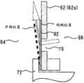
图3是放大表示簧片阀的附近的图2中的主要部分放大图。FIG. 3 is an enlarged view of a main part in FIG. 2 showing the vicinity of the reed valve in an enlarged manner.
图4是表示簧片阀的开阀特性的特性线图。Fig. 4 is a characteristic diagram showing the valve opening characteristics of the reed valve.
图5是表示在本发明的实施方式1中由ECU执行的控制的流程图。FIG. 5 is a flowchart showing control executed by an ECU in Embodiment 1 of the present invention.
图6是用于说明本发明的实施方式2的系统结构的整体结构图。FIG. 6 is an overall configuration diagram illustrating a system configuration according to Embodiment 2 of the present invention.
图7是表示阀执行器的结构的纵截面图。Fig. 7 is a longitudinal sectional view showing the structure of the valve actuator.
图8是放大表示簧片阀的附近的图7中的主要部分放大图。Fig. 8 is an enlarged view of a main part in Fig. 7 showing the vicinity of the reed valve in an enlarged manner.
图9是表示簧片阀的开阀特性的特性线图。Fig. 9 is a characteristic diagram showing the valve opening characteristics of the reed valve.
图10是表示在本发明的实施方式2中由ECU执行的控制的流程图。FIG. 10 is a flowchart showing control executed by the ECU in Embodiment 2 of the present invention.
符号说明Symbol Description
10…发动机(内燃机);12…汽缸;14…吸气通路(压力源、压差产生单元);16…排气通路;18…节气门;20…增压器;22…涡轮;24…压缩机;26…旁通通路;28…废气旁通阀(可动机构);30、90…阀执行器(执行器);32…联杆机构;50…ECU;60…外壳;62…膜片;64…高压室(压力室);66…低压室(压力室);72…驱动杆;74…回位弹簧;76…通气孔(连通部);78、92…簧片阀(压力释放阀);80、82…压力配管;84…负压泵(压力源、差压产生单元);86…压力调整阀(压力产生单元);94…切换阀(压力调整阀、差压产生机构);t…温度;T1…压力释放温度。10...engine (internal combustion engine); 12...cylinder; 14...intake passage (pressure source, pressure difference generating unit); 16...exhaust passage; 18...throttle valve; 20...supercharger; 22...turbo; 24...compression Machine; 26...bypass passage; 28...wastegate valve (movable mechanism); 30, 90...valve actuator (actuator); 32...linkage mechanism; 50...ECU; 60...shell; 62...diaphragm ;64...High pressure chamber (pressure chamber); 66...Low pressure chamber (pressure chamber); 72...Drive rod; 74...Return spring; 76...Air hole (communication); 78, 92...Reed valve (pressure release valve ); 80, 82...pressure piping; 84...negative pressure pump (pressure source, differential pressure generating unit); 86...pressure regulating valve (pressure generating unit); 94...switching valve (pressure regulating valve, differential pressure generating mechanism); t…temperature; T1…pressure release temperature.
具体实施方式Detailed ways
实施方式1Embodiment 1
[实施方式1的结构][Structure of Embodiment 1]
以下,参照图1至图5对本发明的实施方式1进行说明。图1是用于说明本发明的实施方式1的系统结构的整体结构图。本实施方式的系统具备作为内燃机的发动机10,在发动机10的各汽缸12上分别设有燃料喷射阀、火花塞、吸气阀、排气阀等。此外,发动机10具备将吸入空气吸入到各汽缸12的缸内的吸气通路14、和从缸内排出废气的排气通路16,在吸气通路14上设有对吸入空气量进行调整的节气门18。Hereinafter, Embodiment 1 of the present invention will be described with reference to FIGS. 1 to 5 . FIG. 1 is an overall configuration diagram illustrating a system configuration according to Embodiment 1 of the present invention. The system of this embodiment includes an engine 10 as an internal combustion engine, and each cylinder 12 of the engine 10 is provided with a fuel injection valve, a spark plug, an intake valve, an exhaust valve, and the like. In addition, the engine 10 includes an intake passage 14 for sucking intake air into each cylinder 12 and an exhaust passage 16 for discharging exhaust gas from the cylinders, and a throttle for adjusting the amount of intake air is provided on the intake passage 14 Valve 18.
此外,发动机10具备利用排气压对吸入空气进行增压的增压器20。增压器20具备设于排气通路16的涡轮22、和设于吸气通路14的压缩机24。在增压器20动作时,涡轮22接受排气压并旋转,从而对压缩机24进行驱动,由此压缩机24对吸入空气进行压缩、增压。此外,发动机10具备以对涡轮22进行旁通的方式设于排气通路16的旁通通路26、和用于对在旁通通路26流动的废气的量进行调整的废气旁通阀(WGV)28。WGV28是利用阀执行器30经由联杆机构32加以驱动的,构成本实施方式的可动机构。此外,在发动机10上,作为阀执行器30的驱动系统,搭载有后述的压力配管80、82、负压泵84、压力调整阀86等。Also, the engine 10 includes a supercharger 20 that supercharges intake air using exhaust pressure. The supercharger 20 includes a turbine 22 provided in the exhaust passage 16 and a compressor 24 provided in the intake passage 14 . When the supercharger 20 operates, the turbine 22 receives the exhaust pressure and rotates to drive the compressor 24 , whereby the compressor 24 compresses and supercharges the intake air. Also, the engine 10 includes a bypass passage 26 provided in the exhaust passage 16 to bypass the turbine 22 , and a wastegate valve (WGV) for adjusting the amount of exhaust gas flowing through the bypass passage 26 . 28. The WGV 28 is driven by the valve actuator 30 through the link mechanism 32, and constitutes the movable mechanism of the present embodiment. Further, pressure pipes 80 and 82 , a negative pressure pump 84 , a pressure regulating valve 86 , and the like, which will be described later, are mounted on the engine 10 as a drive system for the valve actuator 30 .
进而,本实施方式的系统具备:包含以下的传感器34~44的传感器系统,和对发动机10的运转状态进行控制的ECU(Electronic Control Unit)50。首先,对传感器系统进行说明,曲轴转角传感器34用于输出与发动机10的曲轴的旋转同步的信号,ECU50能够基于该输出对发动机转速和曲轴转角进行检测。此外,空气流量传感器36对吸入空气量进行检测,吸气温度传感器38对吸入空气的温度进行检测。增压压力传感器40对由增压器20增压的吸入空气的压力(增压压力)进行检测。进而,油门开度传感器42用于检测车辆的驾驶员对油门踏板的操作量(油门开度),车速传感器44对车辆的速度进行检测。Furthermore, the system of the present embodiment includes a sensor system including the following sensors 34 to 44 and an ECU (Electronic Control Unit) 50 that controls the operating state of the engine 10 . First, the sensor system will be described. The crank angle sensor 34 outputs a signal synchronized with the rotation of the crankshaft of the engine 10, and the ECU 50 can detect the engine speed and the crank angle based on the output. Furthermore, the air flow sensor 36 detects the amount of intake air, and the intake air temperature sensor 38 detects the temperature of the intake air. The boost pressure sensor 40 detects the pressure of the intake air boosted by the supercharger 20 (boost pressure). Furthermore, the accelerator opening sensor 42 detects the operation amount (accelerator opening) of the accelerator pedal by the driver of the vehicle, and the vehicle speed sensor 44 detects the speed of the vehicle.
此外,在传感器系统中,除了包含上述传感器34~44之外,还包含车辆、发动机的控制所必需的各种传感器(例如对发动机冷却水的温度进行检测的水温传感器、对排气空燃比进行检测的空燃比传感器等),这些传感器与ECU50的输入侧连接。此外,包含燃料喷射阀、火花塞、后述的压力调整阀86等的各种执行器与ECU50的输出侧连接。In addition, the sensor system includes, in addition to the aforementioned sensors 34 to 44, various sensors necessary for the control of the vehicle and the engine (for example, a water temperature sensor for detecting the temperature of the engine cooling water, a sensor for measuring the exhaust air-fuel ratio, etc.). detected air-fuel ratio sensor, etc.), these sensors are connected to the input side of ECU50. In addition, various actuators including a fuel injection valve, a spark plug, a pressure regulating valve 86 described later, and the like are connected to the output side of the ECU 50 .
而且,ECU50,利用传感器系统对发动机的运转信息进行检测,并基于该检测结果对各执行器进行驱动,从而进行运转控制。具体而言,基于曲轴转角传感器34的输出对发动机转速和曲轴转角进行检测,并利用空气流量传感器36对吸入空气量进行检测。此外,基于吸入空气量、发动机转速等计算燃料喷射量,并基于曲轴转角确定燃料喷射时期、点火时期等后,对燃料喷射阀和火花塞进行驱动。进而,ECU50,基于增压压力传感器40等的输出,利用压力调整阀86对WGV28的开度进行调整,并执行后述的增压压力控制。此外,在阀执行器30的温度超过了容许温度的情况下,执行后述的压力释放控制。Furthermore, the ECU 50 detects the operating information of the engine using the sensor system, and drives each actuator based on the detection result to perform operation control. Specifically, the engine speed and the crank angle are detected based on the output of the crank angle sensor 34 , and the intake air amount is detected by the airflow sensor 36 . In addition, the fuel injection amount is calculated based on the intake air amount, the engine speed, etc., and the fuel injection timing, ignition timing, etc. are determined based on the crank angle, and then the fuel injection valve and the spark plug are driven. Furthermore, the ECU 50 adjusts the opening degree of the WGV 28 using the pressure regulating valve 86 based on the output of the supercharging pressure sensor 40 and the like, and executes supercharging pressure control described later. In addition, when the temperature of the valve actuator 30 exceeds the allowable temperature, pressure release control described later is executed.
接着,对阀执行器30的结构进行说明。阀执行器30作为膜片式执行器而构成。即,阀执行器30构成为:根据在后述的膜片62的一侧和另一侧之间产生的差压,发生挠曲变形,由此对WGV28进行驱动。图2是表示阀执行器的结构的纵截面图。该图是将阀执行器沿着配置在该执行器的中心的驱动杆72的轴线剖切后的图。Next, the configuration of the valve actuator 30 will be described. The valve actuator 30 is configured as a diaphragm actuator. That is, the valve actuator 30 is configured to drive the WGV 28 by flexing and deforming according to a differential pressure generated between one side and the other side of the
如图2所示,阀执行器30具备外壳60、膜片62、驱动杆72、回位弹簧74等。外壳60通过金属材料等作为中空的外壳而构成,通过使帽60b与外壳主体60a的开口部嵌合来进行组装。此外,在外壳60a和帽60b的嵌合部形成有用于夹持膜片62的环状凸缘部60c。As shown in FIG. 2 , the valve actuator 30 includes a
膜片62例如通过橡胶、树脂等具有可挠性的材料而形成,配置在外壳60内。膜片62具备:位于膜片62的中央部的有底筒状的杯部62a;从杯部62a的外周凸缘状突出的环状薄壁部62b;和形成于薄壁部62b的外周侧的环状固定部62c。在此,杯部62a和固定部62c作为具有比较高的刚性的厚壁部而形成,固定部62c遍及全周被外壳60的凸缘部60c夹持。此外,薄壁部62b具有柔韧性,形成为可挠曲变形的部位。The
此外,膜片62将外壳60内部划分成高压室64和低压室66。这两个压力室配置在膜片62的一侧和另一侧,分别气密地形成。而且,在外壳60设有分别在外部连接高压室64和低压室66的两个连接口68、70。在阀执行器30动作时,高压室64保持比低压室66高的压力,在这些压力室之间产生将膜片62从高压室64向低压室66推压的方向的差压(以下称作顺方向的差压)。结果,膜片62接受顺方向的差压而朝向低压室66挠曲变形,与驱动杆72一起沿轴向位移。Furthermore, the
驱动杆72例如形成为分段的棒状,其基端侧在外壳60内固定于膜片62的杯部62a。此外,驱动杆72的前端侧从外壳主体60a向外部突出,经由图1中所示的联杆机构32与WGV28连结。此外,回位弹簧74例如由螺旋弹簧等构成,以压缩状态配置在低压室66内。而且,回位弹簧74总是朝向高压室64对膜片62的杯部62a施力。The
接着,在图2的基础上参照图3对设置于阀执行器30的通气孔76、簧片阀78等的结构进行说明。图3是放大表示簧片阀的附近的图2中的主要部分放大图。如图3所示,在膜片62上形成有贯通杯部62a的底面的通气孔76。该通气孔76构成连通高压室64和低压室66的连通部。此外,在杯部62a的底面的从低压室66侧覆盖通气孔76的位置设置有常闭型的簧片阀78。该簧片阀78构成本实施方式的压力释放阀。Next, the structure of the
簧片阀78例如由具有弹性(弹性)的金属、树脂等的薄板形成,其基端侧固定于杯部62a的底面。此外,簧片阀78的前端侧在不挠曲变形的自由状态下保持在图3中实线所示的闭阀位置。在该闭阀位置,簧片阀78从低压室66侧闭塞通气孔76,将高压室64和低压室66之间气密地遮断。The
图4是表示簧片阀的开阀特性的特性线图。如该图所示,簧片阀78,在顺方向的差压未达到规定的开阀压的情况下,保持在上述闭阀位置。另外,在顺方向的差压未达到开阀压这样的闭阀条件中,也包含产生从低压室66朝向高压室64推压膜片62的方向的差压(以下称作逆方向的差压)的情况。另一方面,当顺方向的差压上升到上述开阀压以上而满足开阀条件时,簧片阀78的前端侧以受到差压而弯曲的方式挠曲变形,向图3中虚线所示的开阀位置位移。由此,高压室64和低压室66经由通气孔76连通。Fig. 4 is a characteristic diagram showing the valve opening characteristics of the reed valve. As shown in the figure, the
接着,再次参照图1对阀执行器30的驱动系统亦即压力配管80、82、负压泵84和压力调整阀86进行说明。首先,高压侧的压力配管80用于将阀执行器30的高压室64(连接口68)与吸气通路14连接,该连接位置设定在压缩机24的下游侧且节气门18的上游侧。由此,发动机10的吸气负压或由增压器20进行增压的增压压力(正压)经由配管80向高压室84供给。即,吸气通路14构成向高压室64供给压力的压力源。Next, the drive system of the valve actuator 30 , that is, the pressure piping 80 , 82 , the negative pressure pump 84 , and the pressure adjustment valve 86 will be described with reference to FIG. 1 again. First, the high-pressure side pressure pipe 80 is used to connect the high-pressure chamber 64 (connection port 68 ) of the valve actuator 30 to the intake passage 14 , and the connection position is set at the downstream side of the compressor 24 and the upstream side of the throttle valve 18 . . Accordingly, the intake negative pressure of the engine 10 or the supercharging pressure (positive pressure) boosted by the supercharger 20 is supplied to the high pressure chamber 84 via the pipe 80 . That is, the intake passage 14 constitutes a pressure source that supplies pressure to the high-
另一方面,低压侧的压力配管82将阀执行器30的低压室66(连接口70)与负压泵84连接。负压泵84例如由通过发动机10进行驱动的机械式泵构成,构成经由压力配管82向低压室66供给压力(负压)的压力源。在压力配管82设有压力调整阀86,该压力调整阀86用于对从负压泵84向低压室66供给的负压进行调整。On the other hand, the pressure pipe 82 on the low-pressure side connects the low-pressure chamber 66 (connection port 70 ) of the valve actuator 30 to the negative pressure pump 84 . The negative pressure pump 84 is constituted by, for example, a mechanical pump driven by the engine 10 , and constitutes a pressure source that supplies pressure (negative pressure) to the
压力调整阀86例如由电磁驱动式的三通阀等构成,基于从ECU50输入的驱动信号,将由负压泵84产生的负压的一部分或全部释放到大气中。因而,低压室66的压力根据压力调整阀86的开度从由负压泵84产生的负压变化至接近大气压的值。即,在使压力调整阀86全开的情况下,由负压泵84产生的负压被原封不动地供给至低压室66。此外,在使压力调整阀86全闭的情况下,向低压室66供给大气压。由此,压力调整阀86在高压室64和低压室66之间差生差压,并且使差压的方向和压力值变化。另外,吸气通路14、负压泵84和压力调整阀86构成本实施方式的差压产生机构。The pressure regulating valve 86 is constituted by, for example, an electromagnetically driven three-way valve or the like, and releases part or all of the negative pressure generated by the negative pressure pump 84 to the atmosphere based on a drive signal input from the ECU 50 . Accordingly, the pressure of the low-
(增压压力控制)(boost pressure control)
接着,对由ECU50执行的增压压力控制、和该控制中的阀执行器30的动作进行说明。在增压压力控制中,基于吸气温度传感器38、增压压力传感器40的输出,利用压力调整阀86使上述差压变化,对阀执行器30的动作状态(即、WGV28的开度)进行控制。由此,能够适当地控制增压压力。Next, the supercharging pressure control performed by the ECU 50 and the operation of the valve actuator 30 during this control will be described. In the supercharging pressure control, based on the outputs of the intake air temperature sensor 38 and the supercharging pressure sensor 40, the above-mentioned differential pressure is changed by the pressure regulating valve 86, and the operating state of the valve actuator 30 (that is, the opening degree of the WGV28) is controlled. control. Accordingly, the supercharging pressure can be appropriately controlled.
更具体而言,首先,在吸气空气的温度、增压压力充分低的情况下,不需要限制增压压力,因此停止阀执行器30,并将WGV28保持在闭阀状态。在停止阀执行器30的情况下,例如使压力调整阀86全闭而使低压室66的压力增大至大气压附近,使顺方向的差压减少。由此,合并上述差压和回位弹簧74的弹力的合力沿图2中的箭头B方向作用于膜片62。结果,由于膜片62被保持在停止位置,所以WGV28成为闭阀状态,利用增压器20进行通常的增压动作。此外,在该状态下,利用ECU50将顺方向的差压保持为未达到簧片阀78的开阀压。因而,簧片阀78被保持在闭阀状态,高压室64和低压室66被遮断。More specifically, first, when the temperature of the intake air and the supercharging pressure are sufficiently low, there is no need to limit the supercharging pressure, so the valve actuator 30 is stopped and the WGV 28 is kept in the closed state. When the valve actuator 30 is stopped, for example, the pressure regulating valve 86 is fully closed to increase the pressure of the low-
此外,在增压压力控制中,在吸入空气的温度或增压压力高的情况下,使阀执行器30动作,使WGV28开阀。由此,能够限制增压压力,并能够防止爆震的产生和增压的异常上升。在使阀执行器30动作的情况下,增大压力调整阀86的开度而使作用于低压室66的负压增大,产生(增大)顺方向的差压。由此,合并上述差压和回位弹簧74的弹力的合力沿图2中的箭头A方向作用于膜片62。结果,对于膜片62而言主要是薄壁部62b发生挠曲变形,从而与驱动杆72一起沿箭头A方向位移。该位移经由联杆机构32传递给WGV28,使WGV28开阀。由此,废气的一部分在旁通通路26中流动,涡轮22的转速降低进而限制增压压力。In addition, during the supercharging pressure control, when the temperature of the intake air or the supercharging pressure is high, the valve actuator 30 is operated to open the WGV 28 . Thereby, the supercharging pressure can be limited, and the occurrence of knocking and an abnormal increase in supercharging can be prevented. When the valve actuator 30 is operated, the opening degree of the pressure regulating valve 86 is increased to increase the negative pressure acting on the low-
此外,ECU50,在不执行压力释放控制的通常状态下,在使阀执行器30动作的情况下,利用顺方向的差压使膜片62挠曲变形,并将该差压的压力值保持为未达到簧片阀78的开阀压的值。更具体而言,ECU50将压力调整阀86的开度保持在从全开适当节气的状态,向低压室66供给比由负压泵84产生的负压高(接近大气压)的负压。由此,能够将顺方向的差压调成为未达到簧片阀78的开阀压,并能够将簧片阀78保持在闭阀状态。In addition, when the ECU 50 operates the valve actuator 30 in a normal state where the pressure release control is not executed, the
另外,例如通过适当地设定回位弹簧74的弹力、压力调整阀86的规格、簧片阀78的开阀压力等,能够实现上述说明那样的阀执行器30的动作(相对于膜片62的合力的作用方向、簧片阀78的动作等)。此外,上述增压压力控制,只不过是本实施方式所示的一例,本发明并不限定于此。In addition, for example, by appropriately setting the elastic force of the
(高温时的压力释放控制)(Pressure release control at high temperature)
接着,对由ECU50执行的高温时的压力释放控制、该控制下的阀执行器30的动作进行说明。如果阀执行器30(膜片62)成为过度的高温状态,则例如高压室64内的气体热膨胀而使内部压力上升,有可能导致膜片62破损。因此,在压力释放控制中,在阀执行器30的温度t超过了规定的压力释放温度T1的情况下,从高压室64向低压室66释放压力。Next, the pressure release control at high temperature executed by the ECU 50 and the operation of the valve actuator 30 under this control will be described. When the valve actuator 30 (diaphragm 62 ) becomes excessively high temperature, for example, gas in the
更具体而言,在阀执行器30的温度t超过了压力释放温度T1的情况下,利用压力调整阀86实现簧片阀78的开阀条件(即,顺方向的差压成为簧片阀78的开阀压以上的状态),使簧片阀78开阀。在该情况下,例如使压力调整阀86全开,将由负压泵84产生的负压原封不动地供给至低压室66,使顺方向的差压上升到开阀压以上。由此,由于簧片阀78开阀,所以能够从高压室64经由通气孔76向低压室66释放压力。另外,压力释放温度T1例如设定为不会因高压室64的压力上升而导致膜片62破损的温度的上限值,预先存储于ECU50。More specifically, when the temperature t of the valve actuator 30 exceeds the pressure release temperature T1, the pressure regulating valve 86 is used to realize the valve opening condition of the reed valve 78 (that is, the differential pressure in the forward direction becomes the
另一方面,即使温度t为高温,在车辆正在行驶的情况下,通过行驶风也能够冷却阀执行器30,因此认为进行压力释放控制的必要性低。因此,在本实施方式中,在基于车速传感器44的输出检测出车辆正在行驶的情况(更具体而言,车速为规定的禁止控制速度V1以上的情况)下,禁止压力释放控制。在此,禁止控制速度V1例如作为能够得到由行驶风带来的冷却效果的最低限度的速度而被预先设定。根据该结构,在能够得到由行驶风带来的冷却效果的情况下,由于可以不执行压力释放控制,所以能够尽量减少非常时的控制亦即压力释放控制的执行频率。On the other hand, even if the temperature t is high, the valve actuator 30 can be cooled by the running wind when the vehicle is running, so it is considered that the need for pressure release control is low. Therefore, in the present embodiment, when the vehicle is detected to be running based on the output of the vehicle speed sensor 44 (more specifically, when the vehicle speed is equal to or greater than the predetermined control prohibition speed V1), the pressure relief control is prohibited. Here, the control prohibition speed V1 is set in advance, for example, as the minimum speed at which the cooling effect by the traveling wind can be obtained. According to this configuration, when the cooling effect due to the traveling wind can be obtained, the pressure release control need not be executed, so that the execution frequency of the pressure release control which is an emergency control can be reduced as much as possible.
此外,在加速运转时,由于使阀执行器30动作来进行增压压力控制的情况较多,所以当执行压力释放控制时,有可能妨碍增压压力控制。因此,在本实施方式中,在基于油门开度传感器42的输出检测出加速请求的情况(更具体而言,油门开度为规定的禁止控制开度A1以上的情况)下,禁止压力释放控制。在此,禁止控制开度A1例如与执行增压压力控制的可能性高的加速等级对应地预先设定。根据该结构,在加速运转时能够防止执行压力释放控制,并能够良好地保持运转性。In addition, during the acceleration operation, since the valve actuator 30 is often activated to perform supercharging pressure control, the supercharging pressure control may be hindered when the pressure relief control is executed. Therefore, in the present embodiment, when an acceleration request is detected based on the output of the accelerator opening sensor 42 (more specifically, when the accelerator opening is equal to or greater than the predetermined prohibited control opening A1), the pressure release control is prohibited. . Here, the prohibition control opening A1 is set in advance corresponding to, for example, an acceleration level at which supercharging pressure control is likely to be executed. According to this configuration, it is possible to prevent the execution of the pressure release control during the acceleration operation, and to maintain good operability.
进而,在压力释放控制中,构成为基于发动机10的运转信息来对阀执行器30的温度t进行控制。具体而言,例如基于吸入空气量、发动机转速等计算发动机的输出,基于输出推定地计算温度t。该推定原理所需要的数据由实验等确定,预先存储于ECU50。由此,即使不使用温度传感器等,也能够容易地取得阀执行器30的温度t,能够实现系统的简化和成本降低。此外,也可以构成为在温度t的计算值中反映吸气温度的检测结果、发动机输出的履历、车速等。由此,在外部气温发生了变化时、车辆的高温停止时(所谓高温运转性),也能够准确地推定温度t。Furthermore, in the pressure relief control, the temperature t of the valve actuator 30 is controlled based on the operating information of the engine 10 . Specifically, for example, the output of the engine is calculated based on the intake air amount, the engine speed, and the like, and the temperature t is estimated based on the output. The data necessary for this presumption principle are determined by experiments or the like, and are stored in ECU 50 in advance. Thereby, the temperature t of the valve actuator 30 can be acquired easily without using a temperature sensor etc., and system simplification and cost reduction can be achieved. In addition, a configuration may be adopted in which the detection result of the intake air temperature, the history of the engine output, the vehicle speed, and the like are reflected in the calculated value of the temperature t. Accordingly, the temperature t can be accurately estimated even when the outside air temperature changes or when the vehicle is stopped at a high temperature (so-called high-temperature driving performance).
[用于实现实施方式1的具体处理][Concrete processing for realizing Embodiment 1]
图5是表示在本发明的实施方式1中由ECU50执行的控制的流程图。其中,图5所示的程序在发动机的运转中反复执行。在该程序中,首先最初利用执行器的温度随着发动机输出增大而上升,计算阀执行器30的温度(推定温度)t。FIG. 5 is a flowchart showing control executed by ECU 50 in Embodiment 1 of the present invention. Among them, the routine shown in FIG. 5 is repeatedly executed while the engine is running. In this routine, first, the temperature (estimated temperature) t of the valve actuator 30 is calculated using the increase in the temperature of the actuator as the engine output increases.
具体而言,首先,基于吸入空气量、发动机转速等计算发动机的输出,判定发动机输出是否未达到规定的低输出判定值P1(步骤100)。在该判定成立时,例如使推定温度t下降1℃(步骤102)。此外,在步骤100的判定不成立时,判定发动机输出是否比规定的高输出判定值P2大(步骤104)。在该判定成立时,例如使推定温度t上升1℃(步骤106)。Specifically, first, the engine output is calculated based on the intake air amount, the engine speed, and the like, and it is determined whether the engine output has not reached a predetermined low output determination value P1 (step 100 ). When this determination is established, for example, the estimated temperature t is lowered by 1° C. (step 102 ). In addition, when the determination in step 100 is not established, it is determined whether or not the engine output is greater than a predetermined high output determination value P2 (step 104 ). When this determination is established, for example, the estimated temperature t is increased by 1° C. (step 106 ).
在此,分别设定低输出判定值P1、高输出判定值P2,来作为执行器被维持在一定的温度的发动机输出的最小值、最大值,预先存储于ECU50。通过步骤100~106的处理,能够推定阀执行器30的温度t。另外,该推定处理只不过是本程序所示的一例,本发明并不限定于此。Here, the low output determination value P1 and the high output determination value P2 are respectively set as the minimum value and the maximum value of the engine output at which the actuator is maintained at a constant temperature, and stored in the ECU 50 in advance. Through the processing of steps 100 to 106, the temperature t of the valve actuator 30 can be estimated. In addition, this estimation process is only an example shown in this program, and this invention is not limited to this.
在下一个处理中,执行温度t是否比上述压力释放温度T1大的判定,和车速是否比上述的禁止控制速度V1小的判定(步骤108)。然后,在这两个判定的任一个成立的情况下,判定油门开度是否未达到上述禁止控制开度A1(步骤110)。然后,在这三个判定全部成立的情况下,执行上述压力释放控制,使簧片阀78开阀(步骤112)。此外,在上述三个判定中某一个不成立的情况下,存在阀执行器30的温度没有上升到需要进行压力释放控制的程度、或者车速大到充分产生行驶风的程度、或者有可能进行加速时的增压压力控制。因而,在该情况下,不执行压力释放控制,而执行包括增压压力控制在内的通常时的控制(步骤114)。In the next process, it is judged whether the temperature t is higher than the above-mentioned pressure release temperature T1, and whether the vehicle speed is lower than the above-mentioned prohibition control speed V1 (step 108). Then, when either of these two judgments is established, it is judged whether or not the accelerator opening has not reached the above-mentioned prohibition control opening A1 (step 110). Then, when all of these three judgments are established, the above-mentioned pressure release control is executed to open the reed valve 78 (step 112). In addition, if any of the above-mentioned three judgments is not established, the temperature of the valve actuator 30 has not risen to the extent that the pressure release control is required, or the vehicle speed is high enough to generate the running wind, or there is a possibility that acceleration may be performed. boost pressure control. Therefore, in this case, the pressure relief control is not executed, but the normal control including the supercharging pressure control is executed (step 114 ).
如上述详述那样,根据本实施方式,在阀执行器30成为过度的高温状态时,能够利用压力调整阀86使顺方向的差压上升到开阀压以上,使簧片阀78开阀。由此,能够从高压室64朝向低压室66释放压力,能够防止高压室64的气体热膨胀而导致膜片62破损。因而,能够提高阀执行器30的耐热性,即使在称为高温的排气系统的附近对WGV28进行驱动的情况下,也能够使阀执行器30稳定地动作。As described in detail above, according to the present embodiment, when the valve actuator 30 is in an excessively high temperature state, the pressure regulating valve 86 can increase the differential pressure in the forward direction to the valve opening pressure or more to open the
而且,在本实施方式中,由于采用在高压室64和低压室66之间释放压力的结构,所以将压力释放用的通气孔76、簧片阀78等收纳在与外部遮断的外壳60内。由此,不需要如采用使压力向外壳的外部逃逸的构造的情况那样,设置向外部开口的通气孔等,因此能够可靠地防止尘埃、水分等异物从外部侵入到外壳60内。因而,即使搭载压力释放用的机构,也能够实现可靠性高的执行器。Furthermore, in this embodiment, since the pressure is released between the high-
此外,由于采用在膜片62上设置通气孔76,且利用简单构造的簧片阀78对通气孔76进行开、闭的结构,所以例如即使不将形成压力释放用的通路的部件、复杂的阀装置等搭载于阀执行器30,也能够容易地实现压力释放用的机构。而且,也不需要阀控制用的机构等,仅通过使差压的方向和压力值变化,就能够容易地使簧片阀78开阀。由此,能够使执行器整体小型、轻量化,能够有效地进行该执行器的组装。In addition, since the
进而,在本实施方式中,将作为第一压力源的吸气通路14与高压室64连接,将作为第二压力源的负压泵84与低压室66连接,且利用压力调整阀86调整负压。由此,能够分别向高压室64和低压室66供给不同的压力,能够在高压室64和低压室66之间有效地产生差压。此外,能够利用压力调整阀86准确地控制差压的方向和压力值。Furthermore, in this embodiment, the suction passage 14 as the first pressure source is connected to the
另外,在上述实施方式1中,图5中所示的步骤100~106表示权利要求1、9中的温度取得单元的具体例。此外,步骤108、112表示权利要求1至4中的压力释放单元的具体例,步骤114表示权利要求1、4中的执行器控制单元的具体例。进而,步骤108表示权利要求7中的行驶时禁止释放单元的具体例,步骤110表示权利要求8中的加速时禁止释放单元的具体例。In the first embodiment described above, steps 100 to 106 shown in FIG. 5 represent specific examples of the temperature acquiring means in claims 1 and 9 . In addition, steps 108 and 112 represent specific examples of the pressure relief unit in claims 1 to 4, and step 114 represents a specific example of the actuator control unit in claims 1 and 4. Furthermore, step 108 shows a specific example of the travel prohibition release means in claim 7, and step 110 shows a specific example of the acceleration prohibition release means in claim 8.
实施方式2Embodiment 2
接着,参照图6至图10对本发明的实施方式2进行说明。本实施方式,在簧片阀的构造和阀执行器的驱动系统中,采用与实施方式1不同的结构,以这一点为特征。另外,在本实施方式中,对与上述实施方式1同样的结构要素标注同样的符号,并省略其说明。Next, Embodiment 2 of the present invention will be described with reference to FIGS. 6 to 10 . This embodiment is characterized by adopting a structure different from that of Embodiment 1 in the structure of the reed valve and the driving system of the valve actuator. In addition, in this embodiment, the same code|symbol is attached|subjected to the same component as said Embodiment 1, and description is abbreviate|omitted.
[实施方式2的特征][Features of Embodiment 2]
首先,参照图7至图9对阀执行器90的结构进行说明。图7是表示阀执行器的结构的纵截面图。图8是放大表示簧片阀的附近的图7中的主要部分放大图。此外,图9是表示簧片阀的开阀特性的特性线图。如图7所示,阀执行器90,与实施方式1大致同样,具备外壳60、膜片62、高压室64、低压室66、驱动杆72、回位弹簧74和通气孔76,还具备常闭型的压力释放阀亦即簧片阀92。First, the configuration of the
但是,如图7和图8所示,簧片阀92设置在从高高压侧64覆盖通气孔76的位置。而且,簧片阀92,在高压室64和低压室66之间产生顺方向的差压的情况下,成为自由状态而保持在闭阀位置,从高压室64侧闭塞通气孔76。此外,如图9所示,簧片阀92构成为在产生逆方向的差压而满足了开阀条件的情况下开阀,使通气孔96开通。However, as shown in FIGS. 7 and 8 , the
另一方面,图6是用于说明本发明的实施方式2的系统结构的整体结构图。如该图所示,在阀执行器90的驱动系统中设有由ECU50控制的电磁驱动式的切换阀94。切换阀94例如由具有两个流入端口和一个流出端口的三端口两位置切换阀构成,与压力配管80的中途连接。具体而言,切换阀94的一个流入端口经由压力配管80的上游部80a与吸气通路14连接,另一个流入端口与负压泵84连接。此外,切换阀94的下游端口经由压力配管80的下游部80b与阀执行器90的连接口68连接。On the other hand, FIG. 6 is an overall configuration diagram illustrating a system configuration according to Embodiment 2 of the present invention. As shown in the figure, an electromagnetically driven switching valve 94 controlled by the ECU 50 is provided in the drive system of the
此外,切换阀94根据从ECU50输入的控制信号,切换到图6中所示的位置A、B的某一个位置。由此,阀执行器90的连接口68(高压室64)在切换阀94切换到位置A时与吸气通路14连接,在切换阀94切换到位置B时与负压泵84连接。另外,在本实施方式中,切换阀94构成与压力调整阀86并用的其他压力调整阀。此外,吸气通路14、负压泵84、压力调整阀86和切换阀94构成压力产生单元。In addition, the switching valve 94 is switched to any one of the positions A and B shown in FIG. 6 in accordance with a control signal input from the ECU 50 . Accordingly, the connection port 68 (high pressure chamber 64 ) of the
(增压压力控制)(boost pressure control)
接着,说明增压压力控制的执行时进行的阀执行器90的控制。首先,ECU50,在不执行压力释放控制的通常状态下,将切换阀94切换到位置A。由此,执行器的驱动系统被设定为与实施方式1同样的状态。在该状态下,在使阀执行器90停止的情况下,与实施方式1同样,例如使压力调整阀86全闭而减少顺方向的差压,利用图7中所示的箭头B方向的合力将膜片62保持在停止位置。另一方面,在使阀执行器90动作的情况下,与实施方式1同样,增大压力调整阀86的开度而增大顺方向的差压,利用箭头A方向的合力使膜片62挠曲变形。此外,在上述任一情况下,由于在高压室64和低压室66之间产生顺方向的差压,所以簧片阀92被保持在闭阀状态。因而,ECU50,与实施方式1同样,能够执行增压压力控制。Next, the control of the
(高温时的压力释放控制)(Pressure release control at high temperature)
接着,对高温时的压力释放控制中的执行器90的动作进行说明。ECU50,在执行器的温度t超过了压力释放温度T1的情况下,将切换阀94切换到位置B,并且将压力调整阀86的开度设定在至少不是全开的开度(中间开度或全闭状态)。由此,相对于将负压泵84的负压原封不动地供给至高压室64,通过将比泵的负压高的压力供给至低压室66,在这些压力室间产生逆方向的差压,实现簧片阀92的开阀条件。结果,由于簧片阀92开阀,所以能够经由通气孔76释放压力。Next, the operation of the
因而,在这样构成的本实施方式中,能够得到与实施方式1大致同样的作用效果。此外,与由吸气通路14和负压泵84构成的两个压力源对应地,设置有压力调整阀86和切换阀94,因此能够更有效地控制差压的方向和压力值。Therefore, in the present embodiment configured in this way, substantially the same effects as those of the first embodiment can be obtained. In addition, since the pressure adjustment valve 86 and the switching valve 94 are provided corresponding to the two pressure sources constituted by the suction passage 14 and the negative pressure pump 84, the direction and pressure value of the differential pressure can be controlled more effectively.
此外,在本实施方式中,由于采用簧片阀92从高压室64侧覆盖通气孔76的结构,所以当使膜片62动作时,能够防止低压室66的压力过度增大而损伤膜片62的薄壁部62b。即,存在如下情况:在使高压室64的压力急剧增大时,来不及进行利用压力调整阀86使低压室66的压力降低的动作,在低压室66的压力高的状态下,膜片62朝向低压室66位移。在该情况下,有可能导致如下情况:膜片62的薄壁部62b从低压室66受到高的压力而以向高压室64侧反转的方式变形、损伤。但是,为了避免该损伤,在限制了高压室64的压力上升速度的情况下,阀执行器90和WGV28的响应性降低。Furthermore, in this embodiment, since the
对此,在本实施方式中,在膜片62发生挠曲变形时低压室66的压力高的情况下,利用逆方向的差压使簧片阀92开阀,能够将低压室66的压力向高压室64侧释放。即,即使在使阀执行器90高速动作的情况下,也能够一边抽出低压室66的压力一边使膜片62变形,能够保护薄壁部62b等不受到损伤。On the other hand, in this embodiment, when the pressure of the low-
[用于实现实施方式2的具体处理][Concrete processing for realizing Embodiment 2]
图10是表示在本发明的实施方式2中由ECU执行的控制的流程图。另外,图10所示的程序在发动机的运转中反复执行。在该程序中,首先,通过进行与实施方式1(图5)的步骤100~108同样的处理,推定阀执行器90的温度t,并进行温度和车速的判定处理(步骤200~208)。FIG. 10 is a flowchart showing control executed by the ECU in Embodiment 2 of the present invention. In addition, the routine shown in FIG. 10 is repeatedly executed while the engine is running. In this program, first, the temperature t of the
然后,在步骤208的判定成立时,将切换阀94切换到位置B后执行上述的压力释放控制,并使簧片阀92开阀(步骤210)。此外,在步骤208的判定不成立的情况下,将切换阀94切换到位置B,执行包含增压压力控制的通常的控制(步骤212)。Then, when the determination in step 208 is established, the switching valve 94 is switched to the position B, and the pressure release control described above is executed, and the
另外,在上述实施方式2中,图10中所示的步骤200~206表示权利要求1、9中的温度取得单元的具体例。此外,步骤208、210表示权利要求1~3、5中的压力释放单元的具体例,步骤212表示权利要求1、5中的执行器控制单元的具体例,步骤208表示权利要求7中的行驶时禁止释放单元的具体例。In addition, in the above-mentioned second embodiment, steps 200 to 206 shown in FIG. 10 represent specific examples of the temperature acquisition means in claims 1 and 9 . In addition, steps 208 and 210 represent specific examples of the pressure release unit in claims 1 to 3 and 5,
此外,在实施方式中,以具有高压室64和低压室66的阀执行器30、90为例进行了说明。但是,本发明并不限定于此,例如也能够适用于采用仅具有一个压力室,利用该压力室内的压力与外部的大气压的差压使膜片挠曲变形的结构的执行器。In addition, in embodiment, the
此外,在实施方式中,作为连通高压室64和低压室66的连通部,是在膜片62上设置通气孔76的结构。但是,本发明并不限定于此,例如也可以利用在膜片以外的部位(例如驱动杆72等)设置的贯通孔、或在执行器的外部在外壳主体60a和帽60b之间连接的软管、配管等构成连通部。In addition, in the embodiment, the
此外,在实施方式中采用如下结构,在阀执行器30、90设置连通孔76和簧片阀78、92,利用压力释放控制使簧片阀78、92开阀。但是,本发明并不是一定需要连通部、压力释放阀等的构造物。即,在本发明中,也可以不设置这些构造物,而例如利用压力释放单元(压力释放控制)使从压力源向压力室供给的压力减少。Furthermore, in the embodiment, the
此外,在实施方式中,作为压力源使用吸气通路14和机械式的负压泵84。但是,本发明的压力源并不限定于此,例如也可以采用使用电动泵和排气通路16的结构。In addition, in the embodiment, the air intake passage 14 and the mechanical negative pressure pump 84 are used as the pressure source. However, the pressure source of the present invention is not limited thereto, and for example, a structure using an electric pump and the exhaust passage 16 may also be employed.
此外,在实施方式中,采用利用压力调整阀86和切换阀94对向阀执行器30、90供给的压力进行控制的结构。但是,本发明并不限定于此,例如也可以不使用压力调整阀,而采用能够利用ECU使所产生的压力发生变化的可变式的泵装置等,利用该泵装置构成差压产生单元。Moreover, in embodiment, the structure which controls the pressure supplied to the
进而,在实施方式中,作为通过阀执行器30、90驱动的可动结构,以WGV28为例进行了说明。但是,本发明并不限定于此,也能够适用于搭载于内燃机且由执行器驱动的任意的可动机构。Furthermore, in the embodiment, the WGV28 has been described as an example of a movable structure driven by the
Claims (10)
Translated fromChineseApplications Claiming Priority (1)
| Application Number | Priority Date | Filing Date | Title |
|---|---|---|---|
| PCT/JP2010/052866WO2011104831A1 (en) | 2010-02-24 | 2010-02-24 | Internal combustion engine control device |
Publications (1)
| Publication Number | Publication Date |
|---|---|
| CN102227549Atrue CN102227549A (en) | 2011-10-26 |
Family
ID=44506278
Family Applications (1)
| Application Number | Title | Priority Date | Filing Date |
|---|---|---|---|
| CN2010800018664APendingCN102227549A (en) | 2010-02-24 | 2010-02-24 | Control devices for internal combustion engines |
Country Status (5)
| Country | Link |
|---|---|
| US (1) | US20110225968A1 (en) |
| EP (1) | EP2541016A1 (en) |
| JP (1) | JP4952849B2 (en) |
| CN (1) | CN102227549A (en) |
| WO (1) | WO2011104831A1 (en) |
Cited By (2)
| Publication number | Priority date | Publication date | Assignee | Title |
|---|---|---|---|---|
| CN105960516A (en)* | 2014-02-11 | 2016-09-21 | 博格华纳公司 | Corrosion resistant pneumatic actuator |
| CN113924411A (en)* | 2019-06-03 | 2022-01-11 | 戴姆勒股份公司 | Actuating device for actuating a valve element of an exhaust gas turbocharger |
Families Citing this family (5)
| Publication number | Priority date | Publication date | Assignee | Title |
|---|---|---|---|---|
| JP6112299B2 (en)* | 2013-06-14 | 2017-04-12 | 三菱自動車工業株式会社 | Engine control device |
| GB2519164A (en)* | 2013-10-14 | 2015-04-15 | Gm Global Tech Operations Inc | Method of controlling the pressure of a turbocharger |
| CN104100363A (en)* | 2014-07-28 | 2014-10-15 | 康跃科技股份有限公司 | Differential pressure type pneumatic actuator device |
| DE102014217456B3 (en)* | 2014-09-02 | 2015-08-06 | Continental Automotive Gmbh | Method for determining a drive signal for the actuator of the wastegate of an exhaust gas turbocharger of a motor vehicle |
| DE102016122045B4 (en) | 2015-11-30 | 2022-09-29 | Cummins Inc. | WASTEGATE and ENGINE ASSEMBLY and method of operating an engine |
Citations (5)
| Publication number | Priority date | Publication date | Assignee | Title |
|---|---|---|---|---|
| GB2033007A (en)* | 1978-10-16 | 1980-05-14 | Nissan Motor | Exhaust turbine driven compressor for IC engines |
| US4736589A (en)* | 1984-02-24 | 1988-04-12 | Nissan Motor Co., Ltd. | Device for controlling supercharging pressure of an exhaust gas turbocharger |
| CN1959080A (en)* | 2005-12-05 | 2007-05-09 | 奇瑞汽车有限公司 | Control device of exhaust gas by-pass valve |
| JP2009024502A (en)* | 2007-07-17 | 2009-02-05 | Isuzu Motors Ltd | Exhaust bypass valve |
| DE102007055630A1 (en)* | 2007-11-21 | 2009-05-28 | Bosch Mahle Turbo Systems Gmbh & Co. Kg | Loading system, particularly turbocharger for motor vehicle, has shaft mounted in housing, where shaft carries turbine-sided turbine wheel and compressor-sided compressor wheel |
Family Cites Families (24)
| Publication number | Priority date | Publication date | Assignee | Title |
|---|---|---|---|---|
| GB1240091A (en)* | 1970-01-06 | 1971-07-21 | Ford Motor Co | Spark advance retard device for an internal combustion engine |
| US4237076A (en)* | 1979-03-29 | 1980-12-02 | Schmelzer Corporation | Two stage vacuum break |
| US4403538A (en)* | 1980-09-02 | 1983-09-13 | The Garrett Corporation | Turbocharger control actuator |
| FR2515730A1 (en)* | 1981-11-05 | 1983-05-06 | Renault | IMPROVED DEVICE FOR CONTROLLING THE BOOSTER PRESSURE OF A TURBOCHARGER ENGINE FOR IMPROVING THE DYNAMIC RESPONSE |
| US4566867A (en)* | 1984-07-02 | 1986-01-28 | Alberto Bazan | Dual diaphragm pump |
| US5063744A (en)* | 1988-10-06 | 1991-11-12 | Toyota Jidosha Kabushiki Kaisha | Actuator for controlling intake pressure in sequential turbo-system |
| US5168707A (en)* | 1989-11-21 | 1992-12-08 | Toyota Jidosha Kabushiki Kaisha | Internal combustion engine with a dual turbocharger system |
| US5154058A (en)* | 1991-06-11 | 1992-10-13 | Toyota Jidosha Kabushiki Kaisha | Internal combustion engine with a dual turbocharger system |
| US5294090A (en)* | 1992-11-25 | 1994-03-15 | Orbit Valve Company | Valve snubber |
| US5392691A (en)* | 1993-07-06 | 1995-02-28 | Indian Head Industries, Inc. | Stone shield for air brake actuator with welded yoke |
| US5727529A (en)* | 1994-01-14 | 1998-03-17 | Walbro Corporation | Pressure control valve for a fuel system |
| JP3661280B2 (en)* | 1996-06-19 | 2005-06-15 | 株式会社デンソー | Thermal expansion valve |
| JPH1136877A (en) | 1997-07-18 | 1999-02-09 | Toyota Motor Corp | Negative pressure actuator |
| US20010037724A1 (en)* | 2000-03-08 | 2001-11-08 | Schumacher Mark S. | System for controlling hydraulic actuator |
| GB0111681D0 (en)* | 2001-05-11 | 2001-07-04 | Holset Engineering Co | Turbo charger with waste gate |
| US6490960B1 (en)* | 2001-07-11 | 2002-12-10 | Xerox Corporation | Muscle-emulating PC board actuator |
| JP2004092735A (en)* | 2002-08-30 | 2004-03-25 | Ricoh Elemex Corp | Gas pressure regulator |
| KR100582884B1 (en)* | 2004-09-14 | 2006-05-25 | 삼성전자주식회사 | Thermal Actuation Pump |
| JP4419894B2 (en) | 2005-03-28 | 2010-02-24 | 株式会社デンソー | Wastegate valve control device for internal combustion engine |
| US8197231B2 (en)* | 2005-07-13 | 2012-06-12 | Purity Solutions Llc | Diaphragm pump and related methods |
| DE102005039772A1 (en)* | 2005-08-22 | 2007-03-08 | Prominent Dosiertechnik Gmbh | solenoid |
| WO2007030750A1 (en)* | 2005-09-09 | 2007-03-15 | Board Of Trustees Of The University Of Illinois | Dual chamber valveless mems micropump |
| US7922147B2 (en)* | 2007-01-03 | 2011-04-12 | Zurn Industries, Llc | Diaphragm with segmented insert |
| US7726232B2 (en)* | 2007-02-26 | 2010-06-01 | Pendotech | Diaphragm pump liner for critical process applications |
- 2010
- 2010-02-24CNCN2010800018664Apatent/CN102227549A/enactivePending
- 2010-02-24USUS12/994,946patent/US20110225968A1/ennot_activeAbandoned
- 2010-02-24EPEP10776069Apatent/EP2541016A1/ennot_activeWithdrawn
- 2010-02-24JPJP2010540977Apatent/JP4952849B2/ennot_activeExpired - Fee Related
- 2010-02-24WOPCT/JP2010/052866patent/WO2011104831A1/ennot_activeCeased
Patent Citations (5)
| Publication number | Priority date | Publication date | Assignee | Title |
|---|---|---|---|---|
| GB2033007A (en)* | 1978-10-16 | 1980-05-14 | Nissan Motor | Exhaust turbine driven compressor for IC engines |
| US4736589A (en)* | 1984-02-24 | 1988-04-12 | Nissan Motor Co., Ltd. | Device for controlling supercharging pressure of an exhaust gas turbocharger |
| CN1959080A (en)* | 2005-12-05 | 2007-05-09 | 奇瑞汽车有限公司 | Control device of exhaust gas by-pass valve |
| JP2009024502A (en)* | 2007-07-17 | 2009-02-05 | Isuzu Motors Ltd | Exhaust bypass valve |
| DE102007055630A1 (en)* | 2007-11-21 | 2009-05-28 | Bosch Mahle Turbo Systems Gmbh & Co. Kg | Loading system, particularly turbocharger for motor vehicle, has shaft mounted in housing, where shaft carries turbine-sided turbine wheel and compressor-sided compressor wheel |
Cited By (5)
| Publication number | Priority date | Publication date | Assignee | Title |
|---|---|---|---|---|
| CN105960516A (en)* | 2014-02-11 | 2016-09-21 | 博格华纳公司 | Corrosion resistant pneumatic actuator |
| US10215087B2 (en) | 2014-02-11 | 2019-02-26 | Borgwarner Inc. | Corrosion resistant pneumatic actuator |
| CN113924411A (en)* | 2019-06-03 | 2022-01-11 | 戴姆勒股份公司 | Actuating device for actuating a valve element of an exhaust gas turbocharger |
| US11879379B2 (en) | 2019-06-03 | 2024-01-23 | Daimler Truck AG | Actuating device for actuating a valve element of an exhaust gas turbocharger |
| CN113924411B (en)* | 2019-06-03 | 2024-04-02 | 戴姆勒卡车股份公司 | Actuating device for actuating a valve element of an exhaust gas turbocharger |
Also Published As
| Publication number | Publication date |
|---|---|
| JP4952849B2 (en) | 2012-06-13 |
| US20110225968A1 (en) | 2011-09-22 |
| WO2011104831A1 (en) | 2011-09-01 |
| EP2541016A1 (en) | 2013-01-02 |
| JPWO2011104831A1 (en) | 2013-06-17 |
Similar Documents
| Publication | Publication Date | Title |
|---|---|---|
| JP4952849B2 (en) | Control device for internal combustion engine | |
| US6810667B2 (en) | Bypass valve system of a turbo-charged engine | |
| CN102791988B (en) | Control device for internal combustion engine | |
| RU2647167C2 (en) | Method and system of operating vehicle engine and supercharged engine system | |
| JP5680169B1 (en) | Control device and control method for internal combustion engine | |
| WO2013031920A1 (en) | Supercharger control device for internal combustion engine | |
| US4642991A (en) | Turbocharger control system | |
| WO2017126166A1 (en) | Waste gate valve control method and control device | |
| US20150240704A1 (en) | Supercharging apparatus for engine | |
| JP5526853B2 (en) | Diaphragm type actuator | |
| JP2010090766A (en) | Diaphragm actuator | |
| JP2007077897A (en) | Control device for supercharged engine | |
| CN100476169C (en) | Internal combustion engine with supercharger | |
| JP2005054750A (en) | Turbocharged engine | |
| JP4390790B2 (en) | Wastegate valve control device for an internal combustion engine with a supercharger | |
| JP4229038B2 (en) | Internal combustion engine supercharging system | |
| JP6449661B2 (en) | Internal combustion engine negative pressure system | |
| JP4674561B2 (en) | Valve device | |
| JPH05195798A (en) | Deceleration air bypass valve controller for supercharged engine | |
| KR100391627B1 (en) | boost pressure controlling system of turbocharger | |
| JP5430443B2 (en) | Internal combustion engine supercharging system | |
| JP6385841B2 (en) | Internal combustion engine negative pressure system | |
| JP2007170266A (en) | Engine equipped with turbocharger mechanism | |
| JP3289308B2 (en) | Supercharging pressure control device for supercharged engine | |
| JPH022451B2 (en) |
Legal Events
| Date | Code | Title | Description |
|---|---|---|---|
| C06 | Publication | ||
| PB01 | Publication | ||
| C10 | Entry into substantive examination | ||
| SE01 | Entry into force of request for substantive examination | ||
| C02 | Deemed withdrawal of patent application after publication (patent law 2001) | ||
| WD01 | Invention patent application deemed withdrawn after publication | Application publication date:20111026 |