CN102224664A - Predictive Pulse Width Modulation for High Efficiency Ironless Permanent Magnet Motors Driven by Open Delta H-Bridges - Google Patents
Predictive Pulse Width Modulation for High Efficiency Ironless Permanent Magnet Motors Driven by Open Delta H-BridgesDownload PDFInfo
- Publication number
- CN102224664A CN102224664ACN2009801466487ACN200980146648ACN102224664ACN 102224664 ACN102224664 ACN 102224664ACN 2009801466487 ACN2009801466487 ACN 2009801466487ACN 200980146648 ACN200980146648 ACN 200980146648ACN 102224664 ACN102224664 ACN 102224664A
- Authority
- CN
- China
- Prior art keywords
- msub
- mrow
- pulse width
- duty cycle
- motor
- Prior art date
- Legal status (The legal status is an assumption and is not a legal conclusion. Google has not performed a legal analysis and makes no representation as to the accuracy of the status listed.)
- Pending
Links
Images


Classifications
- F—MECHANICAL ENGINEERING; LIGHTING; HEATING; WEAPONS; BLASTING
- F02—COMBUSTION ENGINES; HOT-GAS OR COMBUSTION-PRODUCT ENGINE PLANTS
- F02D—CONTROLLING COMBUSTION ENGINES
- F02D41/00—Electrical control of supply of combustible mixture or its constituents
- F02D41/20—Output circuits, e.g. for controlling currents in command coils
- H—ELECTRICITY
- H02—GENERATION; CONVERSION OR DISTRIBUTION OF ELECTRIC POWER
- H02P—CONTROL OR REGULATION OF ELECTRIC MOTORS, ELECTRIC GENERATORS OR DYNAMO-ELECTRIC CONVERTERS; CONTROLLING TRANSFORMERS, REACTORS OR CHOKE COILS
- H02P21/00—Arrangements or methods for the control of electric machines by vector control, e.g. by control of field orientation
- G—PHYSICS
- G05—CONTROLLING; REGULATING
- G05B—CONTROL OR REGULATING SYSTEMS IN GENERAL; FUNCTIONAL ELEMENTS OF SUCH SYSTEMS; MONITORING OR TESTING ARRANGEMENTS FOR SUCH SYSTEMS OR ELEMENTS
- G05B11/00—Automatic controllers
- G05B11/01—Automatic controllers electric
- G05B11/26—Automatic controllers electric in which the output signal is a pulse-train
- G05B11/28—Automatic controllers electric in which the output signal is a pulse-train using pulse-height modulation; using pulse-width modulation
- H—ELECTRICITY
- H02—GENERATION; CONVERSION OR DISTRIBUTION OF ELECTRIC POWER
- H02P—CONTROL OR REGULATION OF ELECTRIC MOTORS, ELECTRIC GENERATORS OR DYNAMO-ELECTRIC CONVERTERS; CONTROLLING TRANSFORMERS, REACTORS OR CHOKE COILS
- H02P23/00—Arrangements or methods for the control of AC motors characterised by a control method other than vector control
- H02P23/14—Estimation or adaptation of motor parameters, e.g. rotor time constant, flux, speed, current or voltage
- H—ELECTRICITY
- H02—GENERATION; CONVERSION OR DISTRIBUTION OF ELECTRIC POWER
- H02P—CONTROL OR REGULATION OF ELECTRIC MOTORS, ELECTRIC GENERATORS OR DYNAMO-ELECTRIC CONVERTERS; CONTROLLING TRANSFORMERS, REACTORS OR CHOKE COILS
- H02P27/00—Arrangements or methods for the control of AC motors characterised by the kind of supply voltage
- H02P27/04—Arrangements or methods for the control of AC motors characterised by the kind of supply voltage using variable-frequency supply voltage, e.g. inverter or converter supply voltage
- H02P27/06—Arrangements or methods for the control of AC motors characterised by the kind of supply voltage using variable-frequency supply voltage, e.g. inverter or converter supply voltage using DC to AC converters or inverters
- H02P27/08—Arrangements or methods for the control of AC motors characterised by the kind of supply voltage using variable-frequency supply voltage, e.g. inverter or converter supply voltage using DC to AC converters or inverters with pulse width modulation
- F—MECHANICAL ENGINEERING; LIGHTING; HEATING; WEAPONS; BLASTING
- F02—COMBUSTION ENGINES; HOT-GAS OR COMBUSTION-PRODUCT ENGINE PLANTS
- F02D—CONTROLLING COMBUSTION ENGINES
- F02D41/00—Electrical control of supply of combustible mixture or its constituents
- F02D41/20—Output circuits, e.g. for controlling currents in command coils
- F02D2041/202—Output circuits, e.g. for controlling currents in command coils characterised by the control of the circuit
- F02D2041/2024—Output circuits, e.g. for controlling currents in command coils characterised by the control of the circuit the control switching a load after time-on and time-off pulses
- F02D2041/2027—Control of the current by pulse width modulation or duty cycle control
- F—MECHANICAL ENGINEERING; LIGHTING; HEATING; WEAPONS; BLASTING
- F02—COMBUSTION ENGINES; HOT-GAS OR COMBUSTION-PRODUCT ENGINE PLANTS
- F02D—CONTROLLING COMBUSTION ENGINES
- F02D41/00—Electrical control of supply of combustible mixture or its constituents
- F02D41/20—Output circuits, e.g. for controlling currents in command coils
- F02D2041/202—Output circuits, e.g. for controlling currents in command coils characterised by the control of the circuit
- F02D2041/2051—Output circuits, e.g. for controlling currents in command coils characterised by the control of the circuit using voltage control
- F—MECHANICAL ENGINEERING; LIGHTING; HEATING; WEAPONS; BLASTING
- F02—COMBUSTION ENGINES; HOT-GAS OR COMBUSTION-PRODUCT ENGINE PLANTS
- F02D—CONTROLLING COMBUSTION ENGINES
- F02D41/00—Electrical control of supply of combustible mixture or its constituents
- F02D41/20—Output circuits, e.g. for controlling currents in command coils
- F02D2041/202—Output circuits, e.g. for controlling currents in command coils characterised by the control of the circuit
- F02D2041/2058—Output circuits, e.g. for controlling currents in command coils characterised by the control of the circuit using information of the actual current value
Landscapes
- Engineering & Computer Science (AREA)
- Power Engineering (AREA)
- Physics & Mathematics (AREA)
- General Physics & Mathematics (AREA)
- Automation & Control Theory (AREA)
- Chemical & Material Sciences (AREA)
- Combustion & Propulsion (AREA)
- Mechanical Engineering (AREA)
- General Engineering & Computer Science (AREA)
- Control Of Motors That Do Not Use Commutators (AREA)
- Control Of Ac Motors In General (AREA)
- Control Of Direct Current Motors (AREA)
Abstract
Description
Translated fromChinese权益声明以及引用结合Statement of Interest and Incorporation of Citations
本申请要求DABOUSSI.于2008年9月23日提交的,题目为“PREDICTIVE PWM FOR OPEN DELTA H-BRIDGE DRIVE HIGH EFFICIENCY IRONLESS P.H.METER”的美国临时专利申请第61/194,102号的优先权,其全部内容结合于此作为参考。This application claims priority to U.S. Provisional Patent Application No. 61/194,102, filed September 23, 2008, entitled "PREDICTIVE PWM FOR OPEN DELTA H-BRIDGE DRIVE HIGH EFFICIENCY IRONLESS P.H. METER" by DABOUSSI., in its entirety incorporated herein by reference.
技术领域technical field
本发明涉及一种利用实现脉冲宽度调制极性和类型的最优选择所需的电机参数的可获得性的方法和系统。更具体地,本发明涉及一种使用预测占空比的方法和系统,其使用采用电机参数来确定脉宽调制的幅度和脉冲宽度以及脉宽调制的极性的预测占空比,需要该脉宽调制以在给定操作条件下产生波形。The present invention relates to a method and system that utilizes the availability of motor parameters required to achieve optimal selection of pulse width modulation polarity and type. More specifically, the present invention relates to a method and system for using a predicted duty cycle using motor parameters to determine the amplitude and pulse width of the pulse width modulation and the polarity of the pulse width modulation that requires the pulse Broad modulation to produce a waveform under given operating conditions.
背景技术Background technique
永磁电机是一种交流(AC)电动机,其中通过将电磁场施加到永磁转子所产生的场上而将能量提供给旋转装置。为了控制AC永磁电机,需要始终了解转子永磁体(PM)所产生的磁场的绝对位置。磁体的位置对于确定产生期望的转矩所需的电机定子电流幅度很重要。该操作称为定子电流换向。由于磁体相对于定子旋转,所以磁体位置可以通过测量转子的绝对角位置来计算。绝对位置传感器,如旋转变压器(resolver)和光学编码器,通常用于测量电机转子的绝对角位置。A permanent magnet motor is an alternating current (AC) motor in which energy is supplied to a rotating device by applying an electromagnetic field to a field generated by a permanent magnet rotor. In order to control an AC permanent magnet motor, the absolute position of the magnetic field generated by the rotor permanent magnets (PM) needs to be known at all times. The position of the magnets is important in determining the motor stator current magnitude required to produce the desired torque. This operation is called stator current commutation. As the magnet rotates relative to the stator, the magnet position can be calculated by measuring the absolute angular position of the rotor. Absolute position sensors, such as resolvers and optical encoders, are commonly used to measure the absolute angular position of a motor rotor.
H桥拓扑通常用于驱动开口三角形永磁电机,也可以用于其他类型的电机。H桥是使得能够在任一方向上施加跨过负载的电压的电子电路。术语“H桥”源于如图1A所示的这种电路的典型图形表示。H桥由四个开关组成,这些开关可以是固态的或者机械的。如图1B所示,当开关S1和S4闭合时,开关S2和S3打开,将跨过电动机施加正电压。然而,通过打开开关S1和S4,并且闭合开关S2和S3(图1C),使该电压反向,允许电动机的反向操作。H桥布置可用于使电动机极性反向,但是如果电动机端子短路还可以用于停止电动机。The H-bridge topology is commonly used to drive open delta permanent magnet motors, but it can also be used for other types of motors. An H-bridge is an electronic circuit that enables the application of a voltage across a load in either direction. The term "H-bridge" is derived from the typical pictorial representation of such a circuit as shown in Figure 1A. An H-bridge consists of four switches, which can be solid-state or mechanical. As shown in Figure 1B, when switches S1 and S4 are closed and switches S2 and S3 are open, a positive voltage will be applied across the motor. However, by opening switches S1 and S4, and closing switches S2 and S3 (FIG. 1C), this voltage is reversed, allowing reverse operation of the motor. The H-bridge arrangement can be used to reverse the polarity of the motor, but can also be used to stop the motor if the motor terminals are shorted.
使用H桥来驱动PM电机的一个主要好处是,降低电机绕组中的由脉冲调制功率级的脉动电压波形导致的纹波电流。纹波电流是一种电源直流输出的小的无用的残余周期性变化,该电源源于交流电源。利用H桥驱动PM电机所产生的另一个好处是,H桥允许超过由传统三相逆变器施加的120度的限制来塑造电流波形的高度灵活性。A major benefit of using an H-bridge to drive a PM motor is to reduce the ripple current in the motor windings caused by the pulsating voltage waveform of the pulse-modulated power stage. Ripple current is a small unwanted residual periodic variation in the DC output of a power supply derived from an AC source. Another benefit that arises from driving a PM motor with an H-bridge is that the H-bridge allows a high degree of flexibility in shaping the current waveform beyond the 120-degree limit imposed by conventional three-phase inverters.
为了准确地控制电流并使电流波形中的谐波含量最小化,必须进行鲁棒控制。H桥控制的一个问题是,为了减小电机纹波电流,必须采用单极脉宽调制(PWM)。对于单极PWM,当与双极脉宽调制相比时,实现纹波电流的50%的削减。当在过渡期间(其中电机电动势电压具有与端电压不同的极性)过程中使用单极PWM时,必须采用单极和双极PWM的组合;否则,将导致电流失真。现有技术中只是基于电流波形的符号来选择单极与双极PWM。该传统方法导致在电流波形中产生(将导致电机中增加的发热的)额外的谐波。In order to control the current accurately and minimize the harmonic content in the current waveform, robust control is necessary. One problem with H-bridge control is that in order to reduce the motor ripple current, unipolar pulse-width modulation (PWM) must be used. For unipolar PWM, a 50% reduction in ripple current is achieved when compared to bipolar PWM. When using unipolar PWM during transitions where the motor emf voltage has a different polarity than the terminal voltage, a combination of unipolar and bipolar PWM must be used; otherwise, current distortion will result. In the prior art, the selection of unipolar and bipolar PWM is based only on the sign of the current waveform. This conventional approach results in the creation of additional harmonics in the current waveform that will lead to increased heating in the motor.
发明内容Contents of the invention
本方法和系统通过利用电机温度测量、电机参数、操作条件和电机绕组的动态模型,通过适当地确定何时应当使用单极或双极PWM,来优化脉宽调制的生成。The present method and system optimize pulse width modulation generation by appropriately determining when unipolar or bipolar PWM should be used by utilizing motor temperature measurements, motor parameters, operating conditions, and a dynamic model of the motor windings.
本发明的实施方式涉及一种确定预测占空比的由计算机实现的方法,该方法能够确定用于驱动电机电动机的H桥脉宽调制的幅度和脉冲宽度,该方法包括:确定电机参数,将电机参数输入预测占空比模块中,基于脉宽调制产生算法,为预测占空比确定脉宽调制的最佳极性,以及基于脉宽调制产生算法,为预测占空比确定脉宽调制的最佳类型。Embodiments of the present invention relate to a computer-implemented method of determining a predicted duty cycle capable of determining the amplitude and pulse width of an H-bridge pulse width modulation used to drive an electric motor, the method comprising: determining motor parameters, The motor parameters are input into the predicted duty ratio module, based on the PWM generation algorithm, the optimal polarity of the PWM is determined for the predicted duty ratio, and the optimal polarity of the PWM is determined for the predicted duty ratio based on the PWM generation algorithm. best type.
本发明的实施方式涉及一种确定预测占空比的系统,该系统能够确定用于驱动电机电动机的H桥脉宽调制的幅度和脉冲宽度,该系统包括:用于确定电机参数的装置,用于将电机参数输入到预测占空比模块中的装置,用于基于脉宽调制产生算法为预测占空比确定脉宽调制的最佳极性的装置;以及用于基于脉宽调制产生算法为预测占空比确定脉宽调制的最佳类型的装置。Embodiments of the invention relate to a system for determining a predicted duty cycle capable of determining the amplitude and pulse width of an H-bridge pulse width modulation used to drive an electric motor, the system comprising: means for determining parameters of the electric motor, with means for inputting motor parameters into a predicted duty cycle module, means for determining an optimal polarity of pulse width modulation based on a pulse width modulation generation algorithm for the predicted duty cycle; and means for generating an algorithm based on pulse width modulation as Predicting the duty cycle determines the best type of PWM for the device.
本发明的实施方式进一步涉及一种用于确定预测占空比的计算机可读介质,该计算机可读介质能够确定用于驱动电机电动机的H桥脉宽调制的幅度和脉冲宽度,该述计算机可读介质包括:用于确定电机参数的装置,用于将电机参数输入到预测占空比模块中的装置,用于基于脉宽调制产生算法为预测占空比确定脉宽调制的最佳极性的装置;以及用于基于脉宽调制产生算法为预测占空比确定脉宽调制的最佳类型的装置。Embodiments of the present invention further relate to a computer readable medium for determining a predicted duty cycle capable of determining the amplitude and pulse width of an H-bridge pulse width modulation used to drive an electric motor, said computer can The read medium includes means for determining motor parameters, means for inputting the motor parameters into a predicted duty cycle module, and for determining an optimal polarity of the pulse width modulation for the predicted duty cycle based on a pulse width modulation generation algorithm and means for determining an optimal type of pulse width modulation for a predicted duty cycle based on a pulse width modulation generation algorithm.
用于确定预测占空比的方法(该方法能够确定用于驱动电机电动机的H桥脉宽调制的幅度和脉冲宽度)可以包括预测占空比的类型是单极或双极之一。脉宽调制产生算法为
用于确定预测占空比的系统(该系统能够确定用于驱动电机电动机的H桥脉宽调制的幅度和脉冲宽度)可以进一步包括预测占空比的类型是单极或双极之一。脉宽调制产生算法为
用于确定预测占空比的计算机可读介质(该计算机可读介质能够确定用于驱动电机电动机的H桥脉宽调制的幅度和脉冲宽度)可以进一步包括预测占空比的类型是单极或双极之一。脉宽调制产生算法为其中,Eemf(Tmagnet,rpm)是作为磁体温度和速度的函数的电机反电动势,θelect为在该特定占空比期间内的电机的电角度,Iref是参考电流的输入量,即,处理器要从特定占空比获得的电流量,Rs是电机的相电阻,并且是已知的输入参数,Twinding是线圈绕组的温度,并且也是已知的输入参数,L是电感的电感值,并且也是输入参数,以及Vbus是逆变器的电源电压,并且是由模拟数字转换器测量的量。The computer readable medium for determining the predicted duty cycle (the computer readable medium capable of determining the amplitude and pulse width of the H-bridge pulse width modulation used to drive the electric motor) may further include whether the type of the predicted duty cycle is unipolar or One of bipolar. The pulse width modulation generation algorithm is where Eemf (Tmagnet , rpm) is the motor back EMF as a function of magnet temperature and speed, θelect is the electrical angle of the motor during that particular duty cycle, and Iref is the input quantity of the reference current, i.e. , the amount of current the processor wants to draw from a particular duty cycle,Rs is the phase resistance of the motor and is a known input parameter, Twinding is the temperature of the coil windings and is also a known input parameter, L is the inductance Inductance value, and is also an input parameter, and Vbus is the supply voltage of the inverter, and is a quantity measured by the analog-to-digital converter.
附图说明Description of drawings
通过优选实施方式和附图来描述本发明,其中:The invention is described by preferred embodiments and accompanying drawings, in which:
图1A是H桥一般结构的示意图;Figure 1A is a schematic diagram of the general structure of an H-bridge;
图1B是处于一种基态的H桥的示意图;Figure 1B is a schematic diagram of an H-bridge in a ground state;
图1C是处于另一种基态的H桥的示意图;Figure 1C is a schematic diagram of an H-bridge in another ground state;
图2是用于根据本发明的一个实施方式的电机的磁体的示意图;Figure 2 is a schematic diagram of a magnet for an electric machine according to an embodiment of the present invention;
图3是本发明的一个实施方式中的所述系统的配置的框图;Figure 3 is a block diagram of the configuration of the system in one embodiment of the present invention;
图4是关于本发明的一个实施方式的占空比的示意图;FIG. 4 is a schematic diagram of a duty cycle related to an embodiment of the present invention;
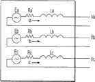
图5A是三相开口三角形电机模型的示意图;5A is a schematic diagram of a three-phase open triangle motor model;
图5B是电机端子的展开图;Fig. 5B is an expanded view of the motor terminal;
图6是确定预测占空比的符号和类型的框图;以及Figure 6 is a block diagram for determining the sign and type of predicted duty cycle; and
图7是为占空比确定最佳脉宽调制的流程图。FIG. 7 is a flowchart for determining an optimal pulse width modulation for a duty cycle.
具体实施方式Detailed ways
申请人发现了通过适当地确定何时应当使用单极脉宽调制或者双极脉宽调制来优化脉宽调制产生的方法和系统。而且,本方法和系统使用预测方法来确定何时应当使用双极PWM或单极PWM,并且,这种预测基于诸如电机温度测量、电机参数、操作条件和电机绕组的动态模型的因素。Applicants have discovered a method and system to optimize pulse width modulation generation by properly determining when unipolar pulse width modulation or bipolar pulse width modulation should be used. Furthermore, the present method and system use predictive methods to determine when bipolar PWM or unipolar PWM should be used, and such predictions are based on factors such as motor temperature measurements, motor parameters, operating conditions, and a dynamic model of the motor windings.
本方法和系统中使用的电动机/发电机的优选实施方式如图2所示。除了别的之外,本方法和系统的电动机/发电机包括无铁芯转子磁体202、204以及定子206。A preferred embodiment of the motor/generator used in the method and system is shown in FIG. 2 . The motor/generator of the present method and system includes, among other things,
图3示出了本发明一个实施方式的框图,本发明的一个实施方式包括具有将信息发送到脉宽调制器306的占空比预测模块304的处理器302。脉宽调制器306切换用于永磁电机308的脉冲。FIG. 3 shows a block diagram of an embodiment of the present invention that includes a
图4示出了关于本方法和系统的一个实施方式的占空比的图示。图4以举例的方式描述了当占空比为单极时,电机和处理器如何确定在占空比中何时采用单极正脉冲或者单极负脉冲。该图示还示出了当电机电动势电压与端电压具有不同极性时的过渡期间,并且必须施加单极和双极脉宽调制的组合以避免电流失真。Figure 4 shows a graphical representation of the duty cycle for one embodiment of the present method and system. Figure 4 depicts by way of example how the motor and processor determine when to employ a unipolar positive pulse or a unipolar negative pulse in the duty cycle when the duty cycle is unipolar. The illustration also shows the transition period when the motor emf voltage has a different polarity than the terminal voltage, and a combination of unipolar and bipolar pulse width modulation must be applied to avoid current distortion.
图5A示出了三相开口三角形构造的电机模型,该电机模型包括三个电源Ea、Eb、Ec,三个电阻Ra、Rb、Rc以及三个电感La、Lb、Lc的示意图,虽然可以考虑其他构造。每相的电流ia、ib、ic也在图5A所示的电机模型中示出。由于三个绕组没有连接至一点,所以电机模型被认为是开口三角形构造。电机能够接收指挥电动机的运动的数字信号。例如,在永磁电机的情况下,通过电动机将电流矢量设定为非常高的DC幅度来启动电动机的旋转。将电流矢量设定为高恒定值使得电动机的电磁场矢量自行与电流矢量对齐。在该初始时刻,电动机的转矩角接近零。Figure 5A shows a three-phase open delta motor model, which includes three power sources Ea , Eb , Ec , three resistors Ra , Rb , Rc and three inductors La , Lb , a schematic diagram ofLc , although other configurations are contemplated. The currentsia ,ib ,ic of each phase are also shown in the motor model shown in Fig. 5A. Since the three windings are not connected to a single point, the motor model is considered an open delta configuration. The motor is capable of receiving digital signals directing the movement of the motor. For example, in the case of a permanent magnet motor, the rotation of the motor is initiated by setting the current vector to a very high DC magnitude through the motor. Setting the current vector to a high constant value causes the motor's electromagnetic field vector to align itself with the current vector. At this initial moment, the torque angle of the motor is close to zero.
图5B是电机端子的展开图,示出了由在功率级504处的H桥驱动的端子。该功率级504包括H桥的四个开关S1、S2、S3、S4。因此,由于电动机具有三相,所以据说电机具有六个开关极。图4B还示出了电源电压Vbus和电容C。FIG. 5B is an expanded view of the motor terminals showing the terminals driven by the H-bridge at the
图6示出了基于占空比的符号和极性确定需要切换哪些开关极,这由处理器通过求解如下算法来完成:Figure 6 shows the determination of which switching poles need to be switched based on the sign and polarity of the duty cycle, which is done by the processor by solving the following algorithm:
其中,in,
Eemf(Tmagnet,rpm)是作为磁体温度和速度的函数的电机反电动势;Eemf (Tmagnet , rpm) is the motor back EMF as a function of magnet temperature and speed;
θelect为在该特定占空比期间内的电机的电角度;θelect is the electrical angle of the motor during the specific duty cycle;
Iref是参考电流的输入量,即,处理器要从特定占空比获得的电流量;Iref is the input quantity of the reference current, that is, the quantity of current that the processor wants to draw from a certain duty cycle;
Rs是电机的相电阻,并且是已知的输入参数;Rs is the phase resistance of the motor and is a known input parameter;
Twinding是线圈绕组的温度,并且也是已知的输入参数;Twinding is the temperature of the coil winding and is also a known input parameter;
L是电感的电感值,并且也是输入参数;以及L is the inductance value of the inductor and is also an input parameter; and
Vbus是逆变器的电源电压,是由模拟数字转换器测量的量。不需要在电机操作期间测量某些或所有输入参数/量,而是可以在操作之前已知,在电机操作之前未知的参数可以在操作期间测量。Vbus is the supply voltage of the inverter and is a quantity measured by an analog-to-digital converter. Some or all input parameters/quantities need not be measured during operation of the motor, but may be known prior to operation, parameters not known prior to operation of the motor may be measured during operation.
上面描述的算法输出dprediction的符号(+或-)将决定需要切换哪些开关极。当dprediction为正值时,则脉宽调制为单极正,因此将开关S1和S2切换为接通,而保持开关S4接通且S3断开,将在正方向上驱动电流。当dprediction为负值时,脉宽调制为单极负,因此将S3和S4切换为接通,而保持开关S2接通且S1断开,将在负方向上驱动电流。The sign (+ or -) of the algorithm output dprediction described above will determine which switch poles need to be switched. When dprediction is positive, then the PWM is unipolar positive, so switching switches S1 and S2 on, while keeping switch S4 on and S3 off, will drive current in the positive direction. When dprediction is negative, the PWM is unipolar negative, so switching S3 and S4 on, while keeping switch S2 on and S1 off, will drive current in the negative direction.
如图6所示,一旦处理器将参数602输入到预测占空比604,该算法就能够确定预测占空比的符号606以及dprediction608的值,这决定了该占空比的极性。而且,处理器确定预测占空比,从而将PI调节器610限制在其实现的电流校正的范围内,即,从而电动机中的实际电流614接近于处理器要从该特定占空比获得的参考电流612。这降低了电机的纹波电流,因此电机电动机更有效地运转。As shown in FIG. 6 , once the processor inputs parameters 602 to the predicted
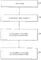
图7示出了用于优化本方法和系统的一个实施方式中的永磁电机的转矩的流程图。在步骤702中,确定电机参数。这些参数可以是在电机操作之前已知的值,和/或它们也可以是在电机操作期间测量的参数。接着,在步骤704中,将电机参数输入占空比预测模块中。然后,在步骤706中,基于脉宽调制产生算法,即上述等式,为预测占空比确定脉宽调制的最佳极性。最后,在步骤708中,基于脉宽调制产生算法为预测占空比确定脉宽调制的最佳类型。Figure 7 shows a flow chart for optimizing the torque of a permanent magnet motor in one embodiment of the method and system. In
虽然,为了在永磁电机中实施而描述上述方法和系统,但是该系统、方法和计算机可读介质可以用于任何类型的具有与速度成比例的反电动势的电动机。Although the methods and systems described above are described for implementation in a permanent magnet electric machine, the system, method, and computer readable medium may be used with any type of electric motor having a back EMF that is proportional to speed.
因此,如现在可以充分理解的,依据本方法和系统的实施方式的上述方法、系统和计算机可读介质,提供了一种确定脉宽调制极性和类型的最佳选择的非常有效的方法。Thus, as can now be fully understood, the above-described method, system and computer readable medium according to embodiments of the present method and system provide a very efficient method of determining the optimal choice of pulse width modulation polarity and type.
已经通过优选实施方式描述了方法和系统。然而,在不脱离由所附权利要求及其法定等价物所限定的方法和系统范围的情况下,可以进行各种修改。Methods and systems have been described with preferred embodiments. However, various modifications may be made without departing from the scope of the method and system as defined in the appended claims and their legal equivalents.
Claims (9)
Applications Claiming Priority (3)
| Application Number | Priority Date | Filing Date | Title |
|---|---|---|---|
| US19410208P | 2008-09-23 | 2008-09-23 | |
| US61/194,102 | 2008-09-23 | ||
| PCT/US2009/058117WO2010036742A1 (en) | 2008-09-23 | 2009-09-23 | Predictive pulse width modulation for an open delta h-bridge driven high efficiency ironless permanent magnet machine |
Publications (1)
| Publication Number | Publication Date |
|---|---|
| CN102224664Atrue CN102224664A (en) | 2011-10-19 |
Family
ID=42060071
Family Applications (1)
| Application Number | Title | Priority Date | Filing Date |
|---|---|---|---|
| CN2009801466487APendingCN102224664A (en) | 2008-09-23 | 2009-09-23 | Predictive Pulse Width Modulation for High Efficiency Ironless Permanent Magnet Motors Driven by Open Delta H-Bridges |
Country Status (8)
| Country | Link |
|---|---|
| US (3) | US8242731B2 (en) |
| EP (2) | EP2340603B1 (en) |
| JP (1) | JP5411278B2 (en) |
| KR (1) | KR101246049B1 (en) |
| CN (1) | CN102224664A (en) |
| AU (1) | AU2009296683B2 (en) |
| CA (1) | CA2740401C (en) |
| WO (1) | WO2010036742A1 (en) |
Cited By (3)
| Publication number | Priority date | Publication date | Assignee | Title |
|---|---|---|---|---|
| CN103743966A (en)* | 2013-11-26 | 2014-04-23 | 广东威灵电机制造有限公司 | PWM module detection method and system in motor driver |
| US8803454B2 (en) | 2008-09-23 | 2014-08-12 | Aerovironment, Inc. | Sensorless optimum torque control for high efficiency ironless permanent magnet machine |
| CN109039189A (en)* | 2018-07-17 | 2018-12-18 | 东南大学 | Two vector prediction control system of permanent magnet synchronous motor and method based on geometric method |
Families Citing this family (6)
| Publication number | Priority date | Publication date | Assignee | Title |
|---|---|---|---|---|
| CN102224664A (en) | 2008-09-23 | 2011-10-19 | 威罗门飞行公司 | Predictive Pulse Width Modulation for High Efficiency Ironless Permanent Magnet Motors Driven by Open Delta H-Bridges |
| FR2993093B1 (en)* | 2012-07-03 | 2014-06-20 | Valeo Sys Controle Moteur Sas | ELECTRIC CIRCUIT FOR EXCITATION OF AT LEAST ONE ELECTRO-MAGNET |
| AU2013408357B2 (en)* | 2013-12-18 | 2016-11-10 | Otis Elevator Company | PWM strategy for regenerative multilevel drive |
| CN104578149B (en)* | 2014-12-23 | 2017-05-17 | 天津大学 | Method for controlling predicted duty cycles of doubly-fed wind power generation system grid-side converter |
| WO2019235655A1 (en)* | 2018-06-05 | 2019-12-12 | 숭실대학교산학협력단 | Multi-phase inverter using independent multi h-bridge |
| CN109149936B (en)* | 2018-09-12 | 2020-06-26 | 西安理工大学 | A Duty Cycle Predictive Control System and Control Algorithm for DC/DC Converters |
Family Cites Families (72)
| Publication number | Priority date | Publication date | Assignee | Title |
|---|---|---|---|---|
| US4332464A (en)* | 1980-09-22 | 1982-06-01 | Xerox Corporation | Interactive user-machine interface method and apparatus for copier/duplicator |
| US4698625A (en)* | 1985-05-30 | 1987-10-06 | International Business Machines Corp. | Graphic highlight adjacent a pointing cursor |
| US4680429A (en)* | 1986-01-15 | 1987-07-14 | Tektronix, Inc. | Touch panel |
| US4790028A (en)* | 1986-09-12 | 1988-12-06 | Westinghouse Electric Corp. | Method and apparatus for generating variably scaled displays |
| US4755811A (en)* | 1987-03-24 | 1988-07-05 | Tektronix, Inc. | Touch controlled zoom of waveform displays |
| US5053758A (en)* | 1988-02-01 | 1991-10-01 | Sperry Marine Inc. | Touchscreen control panel with sliding touch control |
| US5079723A (en)* | 1988-03-04 | 1992-01-07 | Xerox Corporation | Touch dialogue user interface for reproduction machines |
| FI80536C (en)* | 1988-04-15 | 1990-06-11 | Nokia Mobira Oy | MATRISDISPLAY. |
| US5201034A (en)* | 1988-09-30 | 1993-04-06 | Hitachi Ltd. | Interactive intelligent interface |
| US5027110A (en)* | 1988-12-05 | 1991-06-25 | At&T Bell Laboratories | Arrangement for simultaneously displaying on one or more display terminals a series of images |
| US5266949A (en)* | 1990-03-29 | 1993-11-30 | Nokia Mobile Phones Ltd. | Lighted electronic keyboard |
| DE4023318A1 (en)* | 1990-07-21 | 1992-02-20 | Fraunhofer Ges Forschung | METHOD FOR PERFORMING A VARIABLE DIALOG WITH TECHNICAL DEVICES |
| US5119079A (en)* | 1990-09-17 | 1992-06-02 | Xerox Corporation | Touch screen user interface with expanding touch locations for a reprographic machine |
| US5260697A (en)* | 1990-11-13 | 1993-11-09 | Wang Laboratories, Inc. | Computer with separate display plane and user interface processor |
| FI88345C (en)* | 1991-01-29 | 1993-04-26 | Nokia Mobile Phones Ltd | BELYST KEYBOARD |
| JP3123558B2 (en)* | 1991-05-09 | 2001-01-15 | ソニー株式会社 | Information input processing device and method |
| US5341466A (en)* | 1991-05-09 | 1994-08-23 | New York University | Fractal computer user centerface with zooming capability |
| US5202828A (en)* | 1991-05-15 | 1993-04-13 | Apple Computer, Inc. | User interface system having programmable user interface elements |
| US5326270A (en)* | 1991-08-29 | 1994-07-05 | Introspect Technologies, Inc. | System and method for assessing an individual's task-processing style |
| US5757358A (en)* | 1992-03-31 | 1998-05-26 | The United States Of America As Represented By The Secretary Of The Navy | Method and apparatus for enhancing computer-user selection of computer-displayed objects through dynamic selection area and constant visual feedback |
| US5543588A (en)* | 1992-06-08 | 1996-08-06 | Synaptics, Incorporated | Touch pad driven handheld computing device |
| JPH0614405A (en) | 1992-06-26 | 1994-01-21 | Fuji Electric Co Ltd | Electric vehicle electrical system |
| DE69313744T2 (en) | 1992-06-10 | 1998-04-09 | Fuji Electric Co Ltd | AC drive device with variable speed and electric vehicle therefor |
| US5428522A (en)* | 1992-08-17 | 1995-06-27 | Kaman Electromagnetics Corporation | Four quadrant unipolar pulse width modulated inverter |
| US5313148A (en) | 1992-08-21 | 1994-05-17 | Alliedsignal Inc. | Electronically commutated two-axis gyro control system |
| US5982352A (en)* | 1992-09-18 | 1999-11-09 | Pryor; Timothy R. | Method for providing human input to a computer |
| US5465401A (en)* | 1992-12-15 | 1995-11-07 | Texas Instruments Incorporated | Communication system and methods for enhanced information transfer |
| US5335276A (en)* | 1992-12-16 | 1994-08-02 | Texas Instruments Incorporated | Communication system and methods for enhanced information transfer |
| US5463725A (en)* | 1992-12-31 | 1995-10-31 | International Business Machines Corp. | Data processing system graphical user interface which emulates printed material |
| DE69418908T2 (en)* | 1993-01-26 | 2000-01-20 | Sun Microsystems Inc | Method and device for viewing information in a computer database |
| EP0626635B1 (en)* | 1993-05-24 | 2003-03-05 | Sun Microsystems, Inc. | Improved graphical user interface with method for interfacing to remote devices |
| JP2648558B2 (en)* | 1993-06-29 | 1997-09-03 | インターナショナル・ビジネス・マシーンズ・コーポレイション | Information selection device and information selection method |
| US5422656A (en)* | 1993-11-01 | 1995-06-06 | International Business Machines Corp. | Personal communicator having improved contrast control for a liquid crystal, touch sensitive display |
| JP2813728B2 (en)* | 1993-11-01 | 1998-10-22 | インターナショナル・ビジネス・マシーンズ・コーポレイション | Personal communication device with zoom / pan function |
| US5977950A (en)* | 1993-11-29 | 1999-11-02 | Motorola, Inc. | Manually controllable cursor in a virtual image |
| CN1059303C (en)* | 1994-07-25 | 2000-12-06 | 国际商业机器公司 | Apparatus and method for marking text on a display screen in a personal communications device |
| US5568536A (en)* | 1994-07-25 | 1996-10-22 | International Business Machines Corporation | Selective reconfiguration method and apparatus in a multiple application personal communications device |
| JP3565453B2 (en)* | 1994-08-23 | 2004-09-15 | キヤノン株式会社 | Image input / output device |
| DE69524340T2 (en)* | 1994-09-22 | 2002-08-14 | Aisin Aw Co | Touch display for an information entry system |
| US5565888A (en)* | 1995-02-17 | 1996-10-15 | International Business Machines Corporation | Method and apparatus for improving visibility and selectability of icons |
| US5543897A (en)* | 1995-03-07 | 1996-08-06 | Eastman Kodak Company | Reproduction apparatus having touch screen operator interface and auxiliary keyboard |
| JPH0981320A (en)* | 1995-09-20 | 1997-03-28 | Matsushita Electric Ind Co Ltd | Pen input type selection input device and method thereof |
| JPH09146708A (en)* | 1995-11-09 | 1997-06-06 | Internatl Business Mach Corp <Ibm> | Driving method for touch panel and touch input method |
| US6173194B1 (en)* | 1996-04-15 | 2001-01-09 | Nokia Mobile Phones Limited | Mobile terminal having improved user interface |
| JP3462007B2 (en)* | 1996-06-10 | 2003-11-05 | 三菱電機株式会社 | Method for detecting rotation angle and load torque of DC motor, DC motor control device, and electric power steering device |
| US6054990A (en)* | 1996-07-05 | 2000-04-25 | Tran; Bao Q. | Computer system with handwriting annotation |
| AU727387B2 (en)* | 1996-08-28 | 2000-12-14 | Via, Inc. | Touch screen systems and methods |
| US6157935A (en)* | 1996-12-17 | 2000-12-05 | Tran; Bao Q. | Remote data access and management system |
| US5926769A (en)* | 1997-02-18 | 1999-07-20 | Nokia Mobile Phones Limited | Cellular telephone having simplified user interface for storing and retrieving telephone numbers |
| US5977737A (en)* | 1998-09-09 | 1999-11-02 | Labriola, Ii; Donald P. | Digital motor driver circuit and method |
| JP2002247875A (en) | 2001-02-22 | 2002-08-30 | Japan Servo Co Ltd | Fan motor driving circuit |
| US6762580B1 (en)* | 2001-08-16 | 2004-07-13 | Lexmark International, Inc. | Electric motor velocity controller |
| JP4367130B2 (en) | 2001-09-29 | 2009-11-18 | ダイキン工業株式会社 | Phase current detection method, inverter control method, motor control method, and devices thereof |
| JP2003200839A (en) | 2002-01-08 | 2003-07-15 | Unisia Jkc Steering System Co Ltd | Control device for electric power steering device |
| US6703809B2 (en) | 2002-03-05 | 2004-03-09 | Rockwell Automation Technologies, Inc. | Flux position identifier using high frequency injection with the presence of a rich harmonic spectrum in a responding signal |
| US7202622B2 (en)* | 2002-04-30 | 2007-04-10 | International Rectifier Corporation | Method for controlling an electric motor to reduce EMI |
| US6801009B2 (en) | 2002-11-27 | 2004-10-05 | Siemens Vdo Automotive Inc. | Current limitation process of brush and brushless DC motors during severe voltage changes |
| JP4230276B2 (en) | 2003-05-19 | 2009-02-25 | 本田技研工業株式会社 | Brushless DC motor control device |
| US7106024B2 (en) | 2003-09-12 | 2006-09-12 | Rockwell Automation Technologies, Inc. | Filter with increased first harmonic response and reduced phase shift in a wide frequency band for encoderless drive applications |
| US7208908B2 (en) | 2004-07-12 | 2007-04-24 | Honeywell International Inc. | Apparatus and method to control torque and voltage of an AC machine |
| JP2006121891A (en) | 2004-09-24 | 2006-05-11 | Rohm Co Ltd | Fan motor drive device and cooling device |
| US7605804B2 (en)* | 2005-04-29 | 2009-10-20 | Microsoft Corporation | System and method for fine cursor positioning using a low resolution imaging touch screen |
| US7652441B2 (en) | 2005-07-01 | 2010-01-26 | International Rectifier Corporation | Method and system for starting a sensorless motor |
| US7193383B2 (en) | 2005-07-06 | 2007-03-20 | Honeywell International, Inc. | Enhanced floating reference frame controller for sensorless control of synchronous machines |
| JP4425193B2 (en) | 2005-08-16 | 2010-03-03 | 三洋電機株式会社 | Motor position sensorless control device |
| US7358696B2 (en)* | 2005-09-02 | 2008-04-15 | Matsushita Electric Industrial Co., Ltd. | Method and apparatus for PWM drive |
| US7772725B2 (en)* | 2005-09-22 | 2010-08-10 | Eastman Kodak Company | Apparatus and method for current control in H-Bridge load drivers |
| US7525269B2 (en) | 2005-12-14 | 2009-04-28 | Gm Global Technology Operations, Inc. | Method and apparatus for sensorless position control of a permanent magnet synchronous motor (PMSM) drive system |
| US7230837B1 (en)* | 2006-03-27 | 2007-06-12 | North Carolina State University | Method and circuit for cascaded pulse width modulation |
| EP2156542B1 (en)* | 2007-06-04 | 2016-03-30 | Sustainable Energy Technologies | Prediction scheme for step wave power converter and inductive inverter topology |
| CN102224664A (en) | 2008-09-23 | 2011-10-19 | 威罗门飞行公司 | Predictive Pulse Width Modulation for High Efficiency Ironless Permanent Magnet Motors Driven by Open Delta H-Bridges |
| KR101244299B1 (en) | 2008-09-23 | 2013-03-18 | 에어로바이론먼트 인크 | Method and system for sensorless torque control for ironless permanent magnet machine |
- 2009
- 2009-09-23CNCN2009801466487Apatent/CN102224664A/enactivePending
- 2009-09-23CACA2740401Apatent/CA2740401C/ennot_activeExpired - Fee Related
- 2009-09-23WOPCT/US2009/058117patent/WO2010036742A1/enactiveApplication Filing
- 2009-09-23JPJP2011528095Apatent/JP5411278B2/enactiveActive
- 2009-09-23EPEP09816816.4Apatent/EP2340603B1/enactiveActive
- 2009-09-23KRKR1020117008982Apatent/KR101246049B1/ennot_activeExpired - Fee Related
- 2009-09-23EPEP20157527.1Apatent/EP3736954B1/enactiveActive
- 2009-09-23USUS12/565,727patent/US8242731B2/enactiveActive
- 2009-09-23AUAU2009296683Apatent/AU2009296683B2/ennot_activeCeased
- 2012
- 2012-05-01USUS13/460,976patent/US8796978B2/enactiveActive
- 2014
- 2014-08-05USUS14/452,448patent/US20140346995A1/ennot_activeAbandoned
Cited By (5)
| Publication number | Priority date | Publication date | Assignee | Title |
|---|---|---|---|---|
| US8803454B2 (en) | 2008-09-23 | 2014-08-12 | Aerovironment, Inc. | Sensorless optimum torque control for high efficiency ironless permanent magnet machine |
| CN103743966A (en)* | 2013-11-26 | 2014-04-23 | 广东威灵电机制造有限公司 | PWM module detection method and system in motor driver |
| CN103743966B (en)* | 2013-11-26 | 2017-01-18 | 广东威灵电机制造有限公司 | PWM module detection method and system in motor driver |
| CN109039189A (en)* | 2018-07-17 | 2018-12-18 | 东南大学 | Two vector prediction control system of permanent magnet synchronous motor and method based on geometric method |
| CN109039189B (en)* | 2018-07-17 | 2021-11-26 | 东南大学 | Permanent magnet synchronous motor two-vector prediction control method based on geometric method |
Also Published As
| Publication number | Publication date |
|---|---|
| EP2340603A1 (en) | 2011-07-06 |
| EP3736954A1 (en) | 2020-11-11 |
| AU2009296683A1 (en) | 2010-04-01 |
| KR20110053492A (en) | 2011-05-23 |
| AU2009296683B2 (en) | 2014-06-12 |
| US8796978B2 (en) | 2014-08-05 |
| CA2740401A1 (en) | 2010-04-01 |
| EP3736954B1 (en) | 2023-09-06 |
| EP2340603B1 (en) | 2020-04-08 |
| JP2012503961A (en) | 2012-02-09 |
| KR101246049B1 (en) | 2013-03-26 |
| JP5411278B2 (en) | 2014-02-12 |
| US20100201455A1 (en) | 2010-08-12 |
| US20120326651A1 (en) | 2012-12-27 |
| US8242731B2 (en) | 2012-08-14 |
| EP2340603A4 (en) | 2017-11-22 |
| CA2740401C (en) | 2014-11-18 |
| US20140346995A1 (en) | 2014-11-27 |
| WO2010036742A1 (en) | 2010-04-01 |
Similar Documents
| Publication | Publication Date | Title |
|---|---|---|
| US8796978B2 (en) | Predictive pulse width modulation for an open delta H-bridge driven high efficiency ironless permanent magnet machine | |
| US8975856B2 (en) | Method of improving efficiency in a multiphase motor, and motor for implementing such a method | |
| US9716454B2 (en) | Driving circuit and driving method for permanent magnet synchronous motor | |
| CN110492797B (en) | Motor drive circuit | |
| JP2014014197A (en) | Single-phase brushless motor | |
| JP6069953B2 (en) | Switched reluctance motor controller | |
| Gupta et al. | Comparative analysis of Speed control of BLDC motor using PWM and Current Control Techniques | |
| CN109962649B (en) | Motor control device and control method thereof | |
| JP5511923B2 (en) | Electric motor control device | |
| US20100237810A1 (en) | Method and controller for controlling an ipm motor | |
| Bhosale et al. | Performance comparison of Two PWM techniques applied to BLDC motor control | |
| Lee et al. | Implementation of a novel brushless DC motor controller | |
| JP2014233185A (en) | Drive control method of switched reluctance motor and drive controller of switched reluctance motor | |
| CN113169685B (en) | Method for controlling brushless permanent magnet motor | |
| CN108964533A (en) | The control circuit and starting method of single-phase DC brushless motor position-sensor-free | |
| CN102655388B (en) | Method for driving brushless direct current motor in 150-degree conduction mode | |
| Gorbounov | Digital Control of Switched Reluctance Motors Based on Programmable Logic | |
| WO2017161614A1 (en) | Multiphase alternating current electric motor structure and driving circuit thereof | |
| Amin et al. | Development of single phase FEFSM and its excitation circuit for evaluating the control algorithm | |
| Antony et al. | Poly phase BLDC motor drive with ten step commutation | |
| CN116827208A (en) | Motor control device and motor control method | |
| CN118661372A (en) | Back EMF acquisition and measurement using dead time interval | |
| JP2002238276A (en) | Switch reluctance motor, control method thereof, position and angle determination mechanism thereof, inverter and program | |
| CN119298762A (en) | A control method for high-speed electrically excited doubly salient motor based on commutation angle closed loop | |
| Kushwaha et al. | A STUDY AND REVIEW OF OPEN LOOP AND CLOSED LOOP MODEL OF SPEED CONTROL OF BLDC MOTOR |
Legal Events
| Date | Code | Title | Description |
|---|---|---|---|
| C06 | Publication | ||
| PB01 | Publication | ||
| C10 | Entry into substantive examination | ||
| SE01 | Entry into force of request for substantive examination | ||
| C02 | Deemed withdrawal of patent application after publication (patent law 2001) | ||
| WD01 | Invention patent application deemed withdrawn after publication | Application publication date:20111019 |