CN102223909A - Intravascular sheath device and method with graded stiffness - Google Patents
Intravascular sheath device and method with graded stiffnessDownload PDFInfo
- Publication number
- CN102223909A CN102223909ACN2009801467051ACN200980146705ACN102223909ACN 102223909 ACN102223909 ACN 102223909ACN 2009801467051 ACN2009801467051 ACN 2009801467051ACN 200980146705 ACN200980146705 ACN 200980146705ACN 102223909 ACN102223909 ACN 102223909A
- Authority
- CN
- China
- Prior art keywords
- sheath
- strengthening part
- actuating mechanism
- sheath apparatus
- outer tube
- Prior art date
- Legal status (The legal status is an assumption and is not a legal conclusion. Google has not performed a legal analysis and makes no representation as to the accuracy of the status listed.)
- Pending
Links
- 238000000034methodMethods0.000titleclaimsabstractdescription21
- 239000012530fluidSubstances0.000claimsabstractdescription7
- 238000005728strengtheningMethods0.000claimsdescription21
- 230000002792vascularEffects0.000claimsdescription7
- 239000000463materialSubstances0.000claimsdescription6
- 229920000642polymerPolymers0.000claimsdescription6
- 210000004204blood vesselAnatomy0.000claimsdescription5
- 229910001000nickel titaniumInorganic materials0.000claimsdescription4
- 229910052751metalInorganic materials0.000claimsdescription3
- 239000002184metalSubstances0.000claimsdescription3
- 230000004044responseEffects0.000claimsdescription3
- 239000012781shape memory materialSubstances0.000claimsdescription3
- 230000001105regulatory effectEffects0.000claims3
- 239000002689soilSubstances0.000claims2
- 229910045601alloyInorganic materials0.000claims1
- 239000000956alloySubstances0.000claims1
- 230000008602contractionEffects0.000claims1
- KHYBPSFKEHXSLX-UHFFFAOYSA-NiminotitaniumChemical compound[Ti]=NKHYBPSFKEHXSLX-UHFFFAOYSA-N0.000claims1
- 230000003014reinforcing effectEffects0.000abstractdescription9
- 230000002787reinforcementEffects0.000description27
- 238000013461designMethods0.000description10
- 210000003484anatomyAnatomy0.000description8
- 210000001105femoral arteryAnatomy0.000description4
- 238000001356surgical procedureMethods0.000description4
- 238000013459approachMethods0.000description3
- 238000003780insertionMethods0.000description3
- 230000037431insertionEffects0.000description3
- 210000005166vasculatureAnatomy0.000description3
- 238000006073displacement reactionMethods0.000description2
- 238000005516engineering processMethods0.000description2
- 239000003000extruded plasticSubstances0.000description2
- 239000004809TeflonSubstances0.000description1
- 229920006362Teflon®Polymers0.000description1
- 206010068149Vessel perforationDiseases0.000description1
- 238000002583angiographyMethods0.000description1
- 210000001367arteryAnatomy0.000description1
- 239000008280bloodSubstances0.000description1
- 210000004369bloodAnatomy0.000description1
- 210000001715carotid arteryAnatomy0.000description1
- 238000004891communicationMethods0.000description1
- 239000013013elastic materialSubstances0.000description1
- 210000003191femoral veinAnatomy0.000description1
- 238000002594fluoroscopyMethods0.000description1
- 238000011010flushing procedureMethods0.000description1
- 238000002347injectionMethods0.000description1
- 239000007924injectionSubstances0.000description1
- 208000014674injuryDiseases0.000description1
- 210000003127kneeAnatomy0.000description1
- 230000003902lesionEffects0.000description1
- 230000013011matingEffects0.000description1
- 238000000968medical method and processMethods0.000description1
- HLXZNVUGXRDIFK-UHFFFAOYSA-Nnickel titaniumChemical compound[Ti].[Ti].[Ti].[Ti].[Ti].[Ti].[Ti].[Ti].[Ti].[Ti].[Ti].[Ni].[Ni].[Ni].[Ni].[Ni].[Ni].[Ni].[Ni].[Ni].[Ni].[Ni].[Ni].[Ni].[Ni]HLXZNVUGXRDIFK-UHFFFAOYSA-N0.000description1
- 210000000056organAnatomy0.000description1
- 230000002093peripheral effectEffects0.000description1
- 239000004033plasticSubstances0.000description1
- 239000007787solidSubstances0.000description1
- 239000000243solutionSubstances0.000description1
- 239000003351stiffenerSubstances0.000description1
- BFKJFAAPBSQJPD-UHFFFAOYSA-NtetrafluoroetheneChemical compoundFC(F)=C(F)FBFKJFAAPBSQJPD-UHFFFAOYSA-N0.000description1
- 230000009772tissue formationEffects0.000description1
- 238000012546transferMethods0.000description1
- 230000008733traumaEffects0.000description1
- 239000011800void materialSubstances0.000description1
Images


Classifications
- A—HUMAN NECESSITIES
- A61—MEDICAL OR VETERINARY SCIENCE; HYGIENE
- A61M—DEVICES FOR INTRODUCING MEDIA INTO, OR ONTO, THE BODY; DEVICES FOR TRANSDUCING BODY MEDIA OR FOR TAKING MEDIA FROM THE BODY; DEVICES FOR PRODUCING OR ENDING SLEEP OR STUPOR
- A61M25/00—Catheters; Hollow probes
- A61M25/0043—Catheters; Hollow probes characterised by structural features
- A61M25/005—Catheters; Hollow probes characterised by structural features with embedded materials for reinforcement, e.g. wires, coils, braids
- A61M25/0053—Catheters; Hollow probes characterised by structural features with embedded materials for reinforcement, e.g. wires, coils, braids having a variable stiffness along the longitudinal axis, e.g. by varying the pitch of the coil or braid
- A—HUMAN NECESSITIES
- A61—MEDICAL OR VETERINARY SCIENCE; HYGIENE
- A61M—DEVICES FOR INTRODUCING MEDIA INTO, OR ONTO, THE BODY; DEVICES FOR TRANSDUCING BODY MEDIA OR FOR TAKING MEDIA FROM THE BODY; DEVICES FOR PRODUCING OR ENDING SLEEP OR STUPOR
- A61M25/00—Catheters; Hollow probes
- A61M25/0043—Catheters; Hollow probes characterised by structural features
- A61M25/005—Catheters; Hollow probes characterised by structural features with embedded materials for reinforcement, e.g. wires, coils, braids
- A61M25/0051—Catheters; Hollow probes characterised by structural features with embedded materials for reinforcement, e.g. wires, coils, braids made from fenestrated or weakened tubing layer
- A—HUMAN NECESSITIES
- A61—MEDICAL OR VETERINARY SCIENCE; HYGIENE
- A61M—DEVICES FOR INTRODUCING MEDIA INTO, OR ONTO, THE BODY; DEVICES FOR TRANSDUCING BODY MEDIA OR FOR TAKING MEDIA FROM THE BODY; DEVICES FOR PRODUCING OR ENDING SLEEP OR STUPOR
- A61M25/00—Catheters; Hollow probes
- A61M25/0043—Catheters; Hollow probes characterised by structural features
- A61M25/0054—Catheters; Hollow probes characterised by structural features with regions for increasing flexibility
- A—HUMAN NECESSITIES
- A61—MEDICAL OR VETERINARY SCIENCE; HYGIENE
- A61M—DEVICES FOR INTRODUCING MEDIA INTO, OR ONTO, THE BODY; DEVICES FOR TRANSDUCING BODY MEDIA OR FOR TAKING MEDIA FROM THE BODY; DEVICES FOR PRODUCING OR ENDING SLEEP OR STUPOR
- A61M25/00—Catheters; Hollow probes
- A61M25/01—Introducing, guiding, advancing, emplacing or holding catheters
- A—HUMAN NECESSITIES
- A61—MEDICAL OR VETERINARY SCIENCE; HYGIENE
- A61M—DEVICES FOR INTRODUCING MEDIA INTO, OR ONTO, THE BODY; DEVICES FOR TRANSDUCING BODY MEDIA OR FOR TAKING MEDIA FROM THE BODY; DEVICES FOR PRODUCING OR ENDING SLEEP OR STUPOR
- A61M25/00—Catheters; Hollow probes
- A61M25/0043—Catheters; Hollow probes characterised by structural features
- A61M2025/0063—Catheters; Hollow probes characterised by structural features having means, e.g. stylets, mandrils, rods or wires to reinforce or adjust temporarily the stiffness, column strength or pushability of catheters which are already inserted into the human body
- A—HUMAN NECESSITIES
- A61—MEDICAL OR VETERINARY SCIENCE; HYGIENE
- A61M—DEVICES FOR INTRODUCING MEDIA INTO, OR ONTO, THE BODY; DEVICES FOR TRANSDUCING BODY MEDIA OR FOR TAKING MEDIA FROM THE BODY; DEVICES FOR PRODUCING OR ENDING SLEEP OR STUPOR
- A61M25/00—Catheters; Hollow probes
- A61M25/01—Introducing, guiding, advancing, emplacing or holding catheters
- A61M25/06—Body-piercing guide needles or the like
- A61M25/0662—Guide tubes
- A61M2025/0681—Systems with catheter and outer tubing, e.g. sheath, sleeve or guide tube
- A—HUMAN NECESSITIES
- A61—MEDICAL OR VETERINARY SCIENCE; HYGIENE
- A61M—DEVICES FOR INTRODUCING MEDIA INTO, OR ONTO, THE BODY; DEVICES FOR TRANSDUCING BODY MEDIA OR FOR TAKING MEDIA FROM THE BODY; DEVICES FOR PRODUCING OR ENDING SLEEP OR STUPOR
- A61M25/00—Catheters; Hollow probes
- A61M25/01—Introducing, guiding, advancing, emplacing or holding catheters
- A61M25/0102—Insertion or introduction using an inner stiffening member, e.g. stylet or push-rod
Landscapes
- Health & Medical Sciences (AREA)
- Life Sciences & Earth Sciences (AREA)
- Biomedical Technology (AREA)
- Pulmonology (AREA)
- Engineering & Computer Science (AREA)
- Anesthesiology (AREA)
- Biophysics (AREA)
- Heart & Thoracic Surgery (AREA)
- Hematology (AREA)
- Animal Behavior & Ethology (AREA)
- General Health & Medical Sciences (AREA)
- Public Health (AREA)
- Veterinary Medicine (AREA)
- Media Introduction/Drainage Providing Device (AREA)
- Surgical Instruments (AREA)
Abstract
Description
Translated fromChinese发明背景Background of the invention
1.发明领域1. Field of invention
本发明涉及一种在插入脉管域(vascular tract)时减小或防止变形的具有可分级硬度(gradable stiffness)的鞘器具(sheath device)和方法。The present invention relates to a sheath device and method of gradable stiffness that reduce or prevent deformation when inserted into a vascular tract.
2.背景技术2. Background technology
血管内手术(endovascular surgery)已发展成一种用于穿过主血管而到达身体众多部位的微创手术形式。常规地,导管穿过皮肤引入到诸如股动脉或静脉这类的大血管中。经常地,导管传输能够由X-射线或荧光透视方法检测的射线不透性染料。由于血管内手术是微创型的而且比许多常规的还高创伤性的手术具有直接性的好处,因此血管内手术越来越被广泛地采用。Endovascular surgery has evolved as a minimally invasive form of surgery used to access various parts of the body through major blood vessels. Conventionally, catheters are introduced through the skin into large blood vessels such as the femoral artery or vein. Frequently, the catheter delivers a radiopaque dye that can be detected by X-ray or fluoroscopy. Endovascular surgery is becoming more widely used because it is minimally invasive and has immediate benefits over many conventional, more invasive procedures.
通常而言,导管是一种能够插入身腔、管道或血管的管。导管通常允许流体的引流或注射或利用手术仪器进入。许多的使用需要导管是薄的且柔性的(“软”导管或管);在其它情况中,其可以是较大的实心管—“硬”导管。Generally speaking, a catheter is a tube that is inserted into a body cavity, duct or blood vessel. Catheters typically allow drainage or injection of fluids or access with surgical instruments. Many uses require the catheter to be thin and flexible ("soft" catheter or tube); in other cases it may be a larger solid tube - a "hard" catheter.
如本文所使用的,(1)术语“鞘”指的是引导线的外覆盖物。除非上下文以其它方式指定,否则其可与术语“导管”互换使用,并且(2)术语“引导线”指的是用于引入且定位血管内导管的长且柔性的细弹簧。常规地,通常将导管或鞘穿在线上—然后可撤回线,使导管留在原位,如塞尔丁格技术(Seldinger technique)所教授的那样,一种用于到达血管和其它中空器官的医学方法。Seldinger Sl(Catheter Replacement of the Needle in Percutaneous Arteriography;a New Technique).Acta Radiologica(5);368-76(1953)。As used herein, (1) the term "sheath" refers to the outer covering of the guidewire. Unless the context dictates otherwise, it is used interchangeably with the term "catheter," and (2) the term "guidewire" refers to a long, flexible, thin spring used to introduce and position an intravascular catheter. Conventionally, a catheter or sheath is usually threaded over a wire—the wire can then be retracted, leaving the catheter in place, as taught by the Seldinger technique, a surgical procedure used to reach blood vessels and other hollow organs. medical method. Seldinger Sl (Catheter Replacement of the Needle in Percutaneous Arteriography; a New Technique). Acta Radiologica (5); 368-76 (1953).
在介入脉管的操作期间,在需要导管前进穿过弯曲路径的地方可能引起情况,其中可能很难沿着管空隙操纵引导线或其它介入器具(interventional device)。例如,脉管几何形状中的引起与器具前进有关的问题的一个区域是股骨管和主动脉管的接口处。在周围操作(peripheral procedure)期间,器具的进入位置是与所关注区域相对的身体侧面上的股动脉。然后器具必须越过股骨弓(femoral arch)并进入相对的股动脉。在操作期间所使用的介入器具朝着这种弯曲的解剖构造前进时,在股骨/主动脉接口处经常发生器具变形。一般地,在弯曲管对于插入压力的轴向力反应下,常规的介入器具有变形的趋势。在弯曲的解剖构造近端处经常发生器具变形。During procedures that intervene in vessels, situations may arise where it is required that the catheter be advanced through a tortuous path, where it may be difficult to maneuver a guide wire or other interventional device along the vessel void. For example, one area in vessel geometry that causes problems with instrument advancement is at the interface of the femoral and aortic canals. During peripheral procedures, the entry site for the instrument is the femoral artery on the side of the body opposite the area of interest. The instrument must then pass over the femoral arch and into the opposite femoral artery. When an interventional instrument used during a procedure is advanced towards this curved anatomy, instrument deformation often occurs at the femoral/aortic interface. In general, conventional interventional devices have a tendency to deform under the axial force response of the curved tube to the insertion pressure. Instrument deformation often occurs at the proximal end of the curved anatomy.
目前的技术之所以很难克服这种情况,有以下几个原因:This situation is difficult to overcome with current technology for several reasons:
1.引导线的几何形状。引导线必须具有某种柔性,以能够操纵穿过脉管解剖构造而不会剖开管。引导线通常为一种小直径的线(.014″),而且是柔韧且柔软的。当引导线前进穿过任何弯曲的解剖构造时,由于线的尺寸小,线几乎不能抵抗变形。线的近端部分通常会变形,并且如果任何力被传输至线的远端那也是非常少的。1. The geometry of the leading line. The guide wire must have some flexibility to be able to maneuver through the vessel anatomy without dissecting the tube. The guide wire is usually a small diameter wire (.014") and is flexible and soft. Due to the small size of the wire, the wire resists little deformation when advanced through any tortuous anatomy. The wire's The proximal portion is usually deformed and very little if any force is transmitted to the distal end of the wire.
2.引导管或鞘的柔性。引导管和鞘常规地是由加固的挤压的塑料管制成。这些器具是柔软的并且一般提供很少对变形的抵抗。2. The flexibility of the guide tube or sheath. Introducers and sheaths are conventionally made of reinforced extruded plastic tubing. These utensils are flexible and generally offer little resistance to deformation.
3.操作期间所使用的介入器具。介入器具(例如支架输送系统和气球)沿着它们的轴向轴是柔韧的,并且施加轴向力时容易变形。3. Interventional devices used during the procedure. Interventional devices such as stent delivery systems and balloons are flexible along their axial axis and deform easily when axial force is applied.
可获得的大部分器具和技术,不能提供在操作期间遇到弯曲的解剖构造时发生变形的解决方案。如果器具不能前进穿过该弯曲的解剖构造,则操作可能无法被实施,并且对于患者来说后果可能是危险的。Most of the instruments and techniques available, do not provide a solution for deformations that occur when tortuous anatomy is encountered during manipulation. If the instrument cannot be advanced through this tortuous anatomy, the procedure may not be performed and the consequences for the patient may be dangerous.
已知,当鞘的前缘遇到紧箍损伤时,动能会损失。某些方法通过使用应用于鞘的亲水性材料来解决这个问题。然而,这种方法的问题在于外科医生的手往往会滑过鞘的外表面。It is known that kinetic energy is lost when the leading edge of the sheath encounters cuff damage. Some approaches address this problem by using a hydrophilic material applied to the sheath. However, a problem with this approach is that the surgeon's hand tends to slide over the outer surface of the sheath.
被视为在本申请提交之前的美国和外国的专利文件有以下这些:EP131632;EP171682;WO98/5644;US 5,599,326;7,226,466;7,273,487;20060235502;20060258987;20060264907;20070049899;20080045895;20080172037。US and foreign patent documents deemed to be prior to the filing of this application are the following: EP131632; EP171682; WO98/5644; US 5,599,326; 7,226,466;
发明概述Summary of the invention
在这种背景下,期望具有一种带有简单设计的鞘器具,其容易用于需要介入脉管操作的患者。优选地,这种鞘器具可被直觉地使用并且需要最小的手术技巧;如果期望,还能迅速地且具有再现性地越过可包括钙化损伤和纤维组织形成区域的弯曲路径,而不破坏毗邻的组织。In this context, it is desirable to have a sheath device with a simple design that is easy to use for patients requiring interventional vascular procedures. Preferably, such a sheath device can be used intuitively and requires minimal surgical skill; if desired, can quickly and reproducibly traverse tortuous paths that can include areas of calcified lesions and fibrous tissue formation without disrupting adjacent organize.
优选地,通过提供一种不会切开在其远端前方的组织的尖部设计,所公开的鞘器具使脉管穿孔的风险降低,由此避免可能无意地接触而引起的意外组织破裂。Preferably, the disclosed sheath device reduces the risk of vessel perforation by providing a tip design that does not cut tissue anterior to its distal end, thereby avoiding accidental tissue rupture that could be caused by inadvertent contact.
在一个方面,本发明包括一种器具和方法,其减小或防止介入器具的所不希望的变形。发明器具允许轴向力通过介入器具传输至产品的远端,而不扭结或变形。In one aspect, the invention includes a device and method that reduce or prevent unwanted deformation of an interventional device. The inventive device allows axial force to be transmitted through the interventional device to the distal end of the product without kinking or deformation.
期望的是,沿着鞘的长度具有不同等级的硬度。例如,期望鞘的远端部位是松软或柔软的。这会减小由于在鞘的远端和动脉壁中的紧急转弯之间的抵触而另外可能引起的创伤的风险。Desirably, there are different levels of stiffness along the length of the sheath. For example, it is desirable that the distal portion of the sheath be floppy or flexible. This would reduce the risk of trauma that might otherwise be caused by interference between the distal end of the sheath and the sharp turn in the arterial wall.
优选地,外科医生希望不用交换鞘就能确定特定的鞘在中间部位或在邻近其远端的部位中是否为刚性或非刚性的(顺从的)。因此,本发明的一个方面包括一种鞘,该鞘具有沿着其长度变化的弹性模量。在某些实施方式中,鞘可具有沿着其长度可不连续或逐渐地变化的弹性模量。Preferably, the surgeon wishes to determine whether a particular sheath is rigid or non-rigid (compliant) in the medial region or in a region adjacent its distal end without exchanging the sheaths. Accordingly, one aspect of the invention includes a sheath having a modulus of elasticity that varies along its length. In certain embodiments, the sheath can have a modulus of elasticity that can vary discontinuously or gradually along its length.
本发明的另一个方面是提供一种鞘,该鞘能够沿着其长度改变其外径,例如以使远端处的外径可小于近端处的外径。这些方面还可具有对设计支架的适用性。Another aspect of the invention is to provide a sheath capable of varying its outer diameter along its length, for example so that the outer diameter at the distal end may be smaller than the outer diameter at the proximal end. These aspects may also have applicability to designing scaffolds.
为了满足这些需要,提供一种血管内的鞘器械,其包括内管,内管含有外表面和用于引入医用流体或器具的管腔。具有内部表面的外管布置在内管的外部。各自的外表面和内表面在其之间界定空腔。加强部件(stiffening component)至少部分地容纳在空腔的至少部分中。致动机构与加强部件配合。To meet these needs, an intravascular sheath device is provided that includes an inner tube having an outer surface and a lumen for introducing medical fluids or implements. An outer tube having an inner surface is arranged outside the inner tube. The respective outer and inner surfaces define a cavity therebetween. A stiffening component is at least partially housed in at least part of the cavity. The actuating mechanism cooperates with the reinforcing part.
附图简述Brief description of the drawings
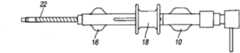
图1为本发明的几个方面的整体透视分解图(实施方式#1);Figure 1 is an overall perspective exploded view of several aspects of the present invention (Embodiment #1);
图2描绘了当器具处于“软”位置时滑动机构的近端位置(等距视图);Figure 2 depicts the proximal position of the slide mechanism (isometric view) when the appliance is in the "soft" position;
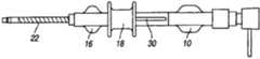
图3描绘了具有外管的滑动机构的近端位置(侧视图);Figure 3 depicts the proximal position (side view) of the sliding mechanism with the outer tube;
图4描绘了具有螺旋形管加强部件的滑动机构的近端位置(侧视图);Figure 4 depicts the proximal position (side view) of the slide mechanism with the helical tube reinforcement;
图5描绘了处于“硬(stiff)”位置的滑动机构的远端部分(等距视图);Figure 5 depicts the distal portion of the slide mechanism in a "stiff" position (isometric view);
图6描绘了包含外管的滑动机构的近端位置(侧视图);Figure 6 depicts the proximal position (side view) of the sliding mechanism comprising the outer tube;
图7描绘了具有螺旋形管加强部件的滑动机构的近端位置,其中隐藏了外管并且其中螺旋以闭合状态构型(侧视图);Figure 7 depicts the proximal position of the sliding mechanism with the helical tube reinforcement member, with the outer tube hidden and with the helix configured in a closed state (side view);
图8描绘了与用于“软”位置和“硬”位置的锁定制动部(locking detent)配合的滑动机构(剖面、等距视图);Figure 8 depicts the sliding mechanism (section, isometric view) cooperating with locking detents for the "soft" and "hard" positions;
图9描绘了包含外管毂滑动轨道的滑动机构,其中导向凸出物(tracking tab)被示出在滑动位置并且在外管毂中设有线型轨道(剖面、等距视图);Fig. 9 depicts a sliding mechanism comprising a sliding track of an outer tube hub, wherein a tracking tab is shown in a sliding position and a linear track is provided in the outer tube hub (section, isometric view);
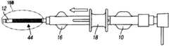
图10描绘了处于打开位置的编织线或聚合物网(实施方式#2);Figure 10 depicts the braided wire or polymer mesh in the open position (Embodiment #2);
图11描绘了处于闭合构型的编织线或聚合物网;Figure 11 depicts a braided wire or polymer mesh in a closed configuration;
图12描绘了滑动机构和外管的近端位置(侧视图);Figure 12 depicts the proximal position of the sliding mechanism and outer tube (side view);
图13和图13A描绘了与编织管加强部件的实施方式配合且隐藏了外管的滑动机构的近端位置(侧视图);Figures 13 and 13A depict the proximal position (side view) of the sliding mechanism mated with an embodiment of the braided tube reinforcement member and concealing the outer tube;
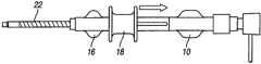
图14描绘了滑动机构的远端位置,其中显示出外管(侧视图);Figure 14 depicts the distal position of the sliding mechanism, showing the outer tube (side view);
图15和图15A描绘了具有编织管加强部件的滑动机构的近端位置,其中隐藏了外管(侧视图);Figures 15 and 15A depict the proximal position of the slide mechanism with braided tube reinforcement, with the outer tube hidden (side view);
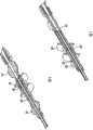
图16描绘了旋转柄状物的“打开”位置(“软”)(实施方式#3,侧视图);Figure 16 depicts the "open" position ("soft") of the rotating handle (embodiment #3, side view);
图17描绘了旋转柄状物旋转至“硬”位置的该实施方式(“闭合”;侧视图);Figure 17 depicts this embodiment with the rotary handle rotated to the "hard" position ("closed"; side view);
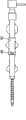
图18描绘了螺旋形旋转柄状物的“打开”位置(“软”)(实施方式#4,侧视图);Figure 18 depicts the "open" position ("soft") of the helical rotating handle (embodiment #4, side view);
图19描绘了螺旋形的旋转,其中柄状物(随着旋转和线性两种运动)已经运动至“硬”位置(“闭合”);Figure 19 depicts the rotation of a helix where the handle (with both rotational and linear movements) has been moved to a "hard" position ("closed");
图20描绘了外管毂中的螺旋形轨道(等距视图);Figure 20 depicts the helical track in the outer tube hub (isometric view);
图21描绘了防止滑动机构意外运动的可选择的安全机构(侧视图);Figure 21 depicts an optional safety mechanism (side view) preventing accidental movement of the sliding mechanism;
图22描绘了安全机构处于“锁定”位置;Figure 22 depicts the safety mechanism in the "locked" position;
图23描绘了安全机构处于“非锁定”位置;Figure 23 depicts the safety mechanism in the "unlocked" position;
图24是图23的实施方式的侧视图;Figure 24 is a side view of the embodiment of Figure 23;
图25是图24的实施方式沿着图24的XXV-XXV线截取的纵向剖面图;Fig. 25 is a longitudinal sectional view of the embodiment of Fig. 24 taken along line XXV-XXV of Fig. 24;
图26是图24的实施方式的俯视图;Figure 26 is a top view of the embodiment of Figure 24;
图27是图26的实施方式沿着图26的XXV Ⅱ-XXV Ⅱ线截取的剖面图;Fig. 27 is a sectional view taken along the XXV Ⅱ-XXV Ⅱ line of Fig. 26 in the embodiment of Fig. 26;
图28描绘了轴的远端部位的另外的剖面细节;以及Figure 28 depicts additional cross-sectional details of the distal portion of the shaft; and
图29是其放大的部分。Fig. 29 is an enlarged part thereof.
优选实施方式详述Detailed Description of Preferred Embodiments
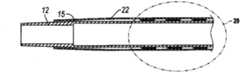
首先翻至附图的图1-3,描绘的是血管内的鞘器械2,其具有内管12,内管12包括用于引入医用器具或流体的管腔26。内管12具有外表面13(最佳地显示于图28-29中)。具有内表面23的外管22定位在内管12的外部。空腔28位于内表面23和外表面13之间。空腔28的至少一部分容纳加强部件20,该加强部件20加固内管12的至少一部分以最小化或防止扭结。在与加强部件20配合中,提供致动机构18。空腔28位于内管12和外管22之间,用于放置管加强部件20。Turning first to Figures 1-3 of the drawings, depicted is an
如本文所使用的,术语“近端(proximal)”和“远端(distal)”描述的是血管内的鞘组件2的相对的轴向端部以及与鞘一起使用的医用器具和其部件的轴向端部。术语“近端”指的是在使用期间构件(或部件)的离外科医生最近的端部。相反地,术语“远端”指的是构件(或部件)的最靠近于鞘组件2的首先插入脉管系统的端部而定位的端部。As used herein, the terms "proximal" and "distal" describe the opposite axial ends of the
在其使用的环境下,血管内的鞘2可包括内管毂10(图1-2),如果需要,内管毂10的近端部分可附接至阀系统6。在一种实施方式中,阀系统6可用作单向阀14,通过单向阀14流体或器具可导入内管12中。如果需要,单向阀6可并入内管毂10。如图1-9所说明的,毂部分10可选择地位于鞘组件2与其它的介入器具4的交接处。在所考虑的每个设计(图1-29)中,单向阀14可选择地用作次要的零件。该阀阻止血液流出器具,但允许将介入器具(引导管、线,等等)引入脉管系统中。其还可以是带有可移除的阀的多件式设计。近端部分还可选择地具有luer锁紧连接(luer lock connection),用于冲洗器具或将流体注射入诸如提供对比的介质(contrast-providing media)这样的系统。In the context of its use, the
优选地,外管22提供光滑的外表面,以利于沿着脉管系统中弯曲的和可能狭窄的槽道行进。在实践中,可将结合物(bond)15(图28)设置于外管22的远端部位,以使其固定至内管12。Preferably,
如果需要,外管毂16(图1-2)可附接至外管22。外管毂16附接至内管毂10。The outer tube hub 16 ( FIGS. 1-2 ) can be attached to the
继续主要地参考图6-9,外管毂16设有轨道30,在一种实施方式中轨道30引导致动或滑动机构18的线型位移。优选地,轨道30限定一个或多个定位特征,定位特征在图8所描绘的实施方式中包括制动部40(远端,硬)和位置38(近端,软)。在图9的实施方式中,沿着设置在外管毂16中的轨道30来引导导向凸出物42。如果需要,如果外科医生需要内管12具有界于将致动机构定位在位置40或38所产生的硬度之间的硬度,则可使致动机构18定位在中间位置。Continuing to refer primarily to FIGS. 6-9 , the
因此将理解,致动机构18与加强部件20(图10-11)相联系并与外管毂16(图1-2)接合。加强部件20具有远端8,其通过结合物15在一端处固定至内管12并在加强部件20的近端处固定至致动机构18。It will thus be appreciated that the
鞘组件2的内管12通常地包括通常由挤压的塑料制成的加固的管形部分。其是软的且顺从的。远端尖部优选为非常柔软,以当器具2被引入诸如股动脉这样的动脉时减小任何管破裂的可能性。在所公开的发明的一种实施方式中,用诸如编织的材料这样的加强部件20来加固内管形部分12的主体,该加强部件20优选地由金属或塑料材料的绞合线制成。这有助于防止管形部分12因易感性(susceptibility)60而扭结,并且给予器具2以抵抗变形的选择性加强特性。The
本发明设计的一个目的是保持目前市场上的产品的功能性,并且在操作期间在需要或期望时给予介入者(interventionalist)一种具有可调节硬度的鞘组件2。One purpose of the design of the present invention is to maintain the functionality of products currently on the market and to give the interventionalist a
本发明设计包括鞘组件2的加强部件20中的改变。这些改变有助于使鞘的内管形部分12的主体得到加强。这种加强允许介入者在期望时更容易地将轴向力传递到器具的远端8,由此有利于器具2穿过弯曲的解剖构造。The inventive design includes changes in the
存在本发明概念的至少四个可选择的实施方式:There are at least four alternative implementations of the inventive concept:
实施方式#1:带有线型滑动装置的螺旋形加强部件Embodiment #1: Helical Stiffener with Linear Slides
在该实施方式中,加强部件20(图2)包括螺旋形管24(图19-20)。在其螺旋形几何形状中毗邻的部分能够被打开或闭合(被压缩),以调节鞘组件2的内管形部分12的横截面硬度。如图2和图6-7中所描绘的,线型路径或轨道30设置在与致动机构或驱动滑动装置18配合的外管毂16中。如图2和图8-9所示,机构18固定在“软”位置中。In this embodiment, the reinforcement member 20 (Fig. 2) comprises a helical tube 24 (Figs. 19-20). Adjacent sections in its helical geometry can be opened or closed (compressed) to adjust the cross-sectional stiffness of the
在图3-4中,致动机构18被描绘成处于近端位置。图3示出了外管22。图4示出加强部件20的螺旋形的实施方式,其中螺旋显示为处于打开位置。In FIGS. 3-4, the
图5-7描绘了处于远端或“硬”位置的致动机构18。在图7中,显示出螺旋形管加强部件20并隐藏了外管22,并且螺旋处于“闭合”状态。5-7 depict the
在一个示例中,加强部件20的近端部位附接至致动机构18,致动机构18使加强部件20以线性运动的方式向远端运动和向近端运动。当滑动机构18处于近端位置时,螺旋打开,由此形成“软”管形部分。当滑动机构处于远端位置时,螺旋闭合,由此形成“硬”管形部分。In one example, the proximal portion of the stiffening
在一种实施方式中,用于管加强部件加固构件20的螺旋形的部分或条的合适材料是像TEFLON或形状记忆材料的聚合物,诸如像NITINOL的镍钛合金。In one embodiment, a suitable material for the helical portion or strip of the tube strengthening
诸如锁定制动部38、40(图8-9)的定位特征能以多种形式设置。在一种实施方式(图8)中,它们显示为阳/阴半球形或拱形的形式(male/female hemispherical or arched form)。它们还可采取一种在致动机构18上钩扣固定(snapping fixture)的形式,致动机构18钩扣至外管毂16中的配合零件中。它们还可采取棘轮型设计(ratcheting-type design)的形式,其中在滑动机构18上的棘爪锁入外管毂16上的棘轮零件(ratcheting detail),或反之亦然。对于任何一个设计,棘爪能够被按压并保持打开,以返回至“软”位置。有多种方式将滑动机构18锁定在“软”和“硬”位置中。图8-9中仅示出一种形式。Locating features such as locking
在图9的实施方式中,致动机构18包含在设置于外管毂16中的线型轨道30内滑动的导向凸出物42。轨道30和凸出物42接合允许平稳运动且将线性力传递至加强部件20。加强部件20能够被固定至滑动机构18上的导向凸出物42。In the embodiment of FIG. 9 , the
滑动机构18和管加强部件20的另外的设计变形如下所述。Additional design variations of the
实施方式#2:带有线型滑动装置的编织的加强部件Embodiment #2: Braided Reinforcement Components with Linear Slides
在该实施方式中,加强部件20(图10-13A)在该实施方式中包括布置成管形构型的编织的或绞合的(stranded)线或网44。编织的几何形状设置成以便各股之间的开口能够通过线性运动而打开和闭合。打开位置46和闭合位置48的改变密度调节部件20的管形部分的横截面硬度,由此形成“软”(图10)状态和“硬”(图11)状态。In this embodiment, the reinforcement member 20 ( FIGS. 10-13A ) comprises, in this embodiment, braided or stranded wires or
在一种方法中,加强部件20包括形成圆柱形编织物的交织的螺旋定向丝(interwoven spirally-oriented filament)的柔性绞合线。当通过致动机构18使拉力施加至加强部件20时,部件20往往变得更硬。在一种实施方式中的部件20可选择地在每一端具有配合在内管12上的开口。加强部件20随着其纵向地拉伸而径向地收缩。在使用中,当在加强部件20的近端施加拉力并且该力在远端被对抗(oppose)从而拉伸加强部件20时,加强部件20将在横向方向紧缩,由此,随着所施加的纵向力的增大,从而越来越更加牢固地夹紧内管12。优选地,绞合线由诸如聚合物或镍-钛合金这样的能恢复原状的、实质上非弹性的材料制成。另外地或可选择地,还可采用诸如编织的聚合物(图10-11)的其它材料。在一种实施方式中,在横截面上,绞合线被螺旋形地定位并且每单股优选地具有圆形或椭圆形的横截面。因此,部件20包括通过纵向张力而在内管12的至少一部分上且沿着内管12的至少一部分被紧贴地向下拉伸的圆柱形编织物。In one approach, the reinforcing
如图10-15A中所示,加强部件20的近端9附接至致动机构18,致动机构18使加强部件20以线性运动的方式向远端运动和向近端运动。当滑动机构18处于近端位置(图10)时,编织线打开,由此形成“软”管形部分。当滑动机构18处于远端位置时,编织的绞合线相对地闭合(图11),由此形成“硬”管形部分。在图13、13A、15、15A中,隐藏了外管22。As shown in Figures 10-15A, the proximal end 9 of the
实施方式#3:旋转的滑动机构Embodiment #3: Rotating Slide Mechanism
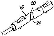
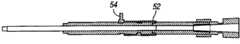
在该实施方式中(图16、图17),致动机构18从线性运动改变成旋转或螺旋形运动。旋转运动能够用于螺旋形加强部件20(实施方式#1)。旋转运动将使管加强部件20(图18-20)的螺旋50(helix)“缠绕”,由此改变其横截面硬度。In this embodiment (Figs. 16, 17), the
在图16中,旋转柄状物52显示为处于“打开”位置。在图17中,旋转柄状物52显示为已旋转至“闭合”或“硬”位置。In Figure 16, the rotation handle 52 is shown in the "open" position. In Figure 17, the rotation handle 52 is shown rotated to the "closed" or "hard" position.
实施方式#4:螺旋形致动机构Embodiment #4: Helical Actuation Mechanism
在该实施方式中(图18-20),致动机构18的运动基本为螺旋形。螺旋形位移能够用于螺旋形管加强部件(实施方式#1)和编织管加强部件(实施方式#2)。螺旋运动将使管加强部件20的螺旋50“缠绕”,由此改变其横截面硬度。螺旋形行进的线性运动15使编织线44压缩和解压缩,由此改变它的横截面硬度。In this embodiment (Figs. 18-20), the motion of the
在优选的实施方式中,滑动机构18的螺旋形运动是逆时针方向,以适应外科医生所期望的操作。大多数外科医生被训练成使用顺时针方向的旋转运动将鞘插入管中。通过使用逆时针方向的运动使鞘得以加强,致动机构18意外接合的可能性将减小。这描绘在图18-20中。图20去除了驱动滑动装置18。该图是描绘设置在外管毂16中的螺旋50的更具体的视图。In a preferred embodiment, the helical movement of the
图21-26中描绘了一种形式的安全机构。为防止滑动机构18的意外运动,安全特征54能选择地并入旋转柄状物52或外管毂16中。如果需要,安全机构54能并入任何设计部件中。在所示的实施方式中,安全机构54描绘成是一种可移除的、一次性部件。在使用中,安全机构54将在操作滑动机构18之前移除。图24描绘的是侧视图;图25是该侧视图的剖面图;及图26是俯视图;以及图27显示为该俯视图的剖面图,其中安全特征54已移除。One form of safety mechanism is depicted in Figures 21-26. To prevent inadvertent movement of the
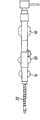
图28-29是描绘鞘组件2的远端的可选择的细节的横截面图。图28-29所说明的是内管12、外管22、螺旋形截断管(helically cut tube)24和位于内管与外管之间的空腔28。应理解在图9中,螺旋形截断管24可被在某些实施方式中由编织形式的加强部件20代替。28-29 are cross-sectional views depicting selected details of the distal end of the
根据应用,本发明的选择性实施方式包括长度为例如19cm、23-25cm、45cm、50cm或65cm的鞘。长度的选择是基于插入位置和欲处理的解剖结构区域—例如,在膝盖下方插入、颈动脉等等。以下是用于本公开内容中的参考数字和其指代的结构部件的列表:Depending on the application, an alternative embodiment of the invention comprises a sheath having a length of eg 19 cm, 23-25 cm, 45 cm, 50 cm or 65 cm. The choice of length is based on the insertion site and the anatomical region to be treated—eg, insertion below the knee, carotid artery, etc. The following is a list of reference numbers used in this disclosure and the structural components they refer to:
虽然已说明并描述了本发明的实施方式,但不是意指这些实施方式说明并描述了本发明所有可能的形式。更确切地,说明书中使用的文字是描述性文字,而不是限制性文字,并且应理解,可以进行各种改变而不脱离本发明的精神和范围。While embodiments of the invention have been illustrated and described, it is not intended that these embodiments illustrate and describe all possible forms of the invention. Rather, the words used in the specification are words of description rather than limitation, and it is understood that various changes may be made without departing from the spirit and scope of the invention.
Claims (25)
Applications Claiming Priority (3)
| Application Number | Priority Date | Filing Date | Title |
|---|---|---|---|
| US12/235,894US8663196B2 (en) | 2008-09-23 | 2008-09-23 | Endovascular sheath with gradable stiffness device and method |
| US12/235,894 | 2008-09-23 | ||
| PCT/US2009/057380WO2010036560A1 (en) | 2008-09-23 | 2009-09-18 | Endovascular sheath with gradable stiffness device and method |
Publications (1)
| Publication Number | Publication Date |
|---|---|
| CN102223909Atrue CN102223909A (en) | 2011-10-19 |
Family
ID=42038395
Family Applications (1)
| Application Number | Title | Priority Date | Filing Date |
|---|---|---|---|
| CN2009801467051APendingCN102223909A (en) | 2008-09-23 | 2009-09-18 | Intravascular sheath device and method with graded stiffness |
Country Status (4)
| Country | Link |
|---|---|
| US (1) | US8663196B2 (en) |
| EP (1) | EP2326380A4 (en) |
| CN (1) | CN102223909A (en) |
| WO (1) | WO2010036560A1 (en) |
Cited By (10)
| Publication number | Priority date | Publication date | Assignee | Title |
|---|---|---|---|---|
| CN103156719A (en)* | 2011-12-16 | 2013-06-19 | 科维蒂恩有限合伙公司 | Occlusive implant delivery devices and associated methods |
| CN106573126A (en)* | 2014-07-28 | 2017-04-19 | 纽罗科公司 | transcarotid neurovascular catheter |
| CN110124179A (en)* | 2019-05-20 | 2019-08-16 | 王奎重 | A kind of hardness is adjustable and the interposing catheter of head end direction-agile |
| CN110916746A (en)* | 2020-02-18 | 2020-03-27 | 上海介入医疗器械有限公司 | Pusher and intervene conveying system |
| CN111110984A (en)* | 2013-07-16 | 2020-05-08 | 柯惠有限合伙公司 | Microcatheter with modified PTFE liner |
| US10864357B2 (en) | 2014-09-04 | 2020-12-15 | Silk Road Medical, Inc. | Methods and devices for transcarotid access |
| US11103627B2 (en) | 2008-12-23 | 2021-08-31 | Silk Road Medical, Inc. | Methods and systems for treatment of acute ischemic stroke |
| US11291799B2 (en) | 2013-12-23 | 2022-04-05 | Silk Road Medical, Inc. | Transcarotid neurovascular catheter |
| CN115297922A (en)* | 2020-03-30 | 2022-11-04 | 美敦力公司 | 3D printed splines on medical devices and methods of making the same |
| CN118743571A (en)* | 2024-09-04 | 2024-10-08 | 湖南省华芯医疗器械有限公司 | Introducing sheath, endoscope assembly and method of using the same |
Families Citing this family (20)
| Publication number | Priority date | Publication date | Assignee | Title |
|---|---|---|---|---|
| US10118020B2 (en) | 2011-12-07 | 2018-11-06 | Traumatek Solutions B.V. | Devices and methods for endovascular access and therapy |
| US9439653B2 (en) | 2011-12-07 | 2016-09-13 | Traumatek Solutions B.V. | Devices and methods for endovascular access and therapy |
| US9044575B2 (en) | 2012-10-22 | 2015-06-02 | Medtronic Adrian Luxembourg S.a.r.l. | Catheters with enhanced flexibility and associated devices, systems, and methods |
| EP2996754B1 (en) | 2013-05-18 | 2023-04-26 | Medtronic Ardian Luxembourg S.à.r.l. | Neuromodulation catheters with shafts for enhanced flexibility and control and associated devices and systems |
| EP3313289B1 (en) | 2015-06-23 | 2021-03-17 | Traumatek Solutions B.V. | Vessel cannulation device |
| JP7082052B2 (en)* | 2015-09-03 | 2022-06-07 | ネプチューン メディカル インク. | A device for advancing the endoscope in the small intestine |
| EP3344323B1 (en) | 2015-09-04 | 2019-02-27 | Petrus A. Besselink | Flexible and steerable device |
| EP4032578A1 (en) | 2016-07-13 | 2022-07-27 | Perfuze Limited | High flexibility, kink resistant catheter shaft |
| EP3500151A4 (en) | 2016-08-18 | 2020-03-25 | Neptune Medical Inc. | DEVICE AND METHOD FOR IMPROVED VISUALIZATION OF THE SMALL BOWEL |
| JP7379321B2 (en) | 2017-07-20 | 2023-11-14 | ネプチューン メディカル インク. | Dynamically rigid overtube |
| CN111465420B (en) | 2017-12-15 | 2023-04-18 | 佩尔福兹有限公司 | Improved catheter and apparatus and system incorporating same |
| US12059128B2 (en) | 2018-05-31 | 2024-08-13 | Neptune Medical Inc. | Device and method for enhanced visualization of the small intestine |
| CN112714658A (en) | 2018-07-19 | 2021-04-27 | 海王星医疗公司 | Dynamic rigidized composite medical structure |
| WO2020214221A1 (en) | 2019-04-17 | 2020-10-22 | Neptune Medical Inc. | Dynamically rigidizing composite medical structures |
| US11793392B2 (en) | 2019-04-17 | 2023-10-24 | Neptune Medical Inc. | External working channels |
| CA3178444A1 (en) | 2020-03-30 | 2021-10-07 | Neptune Medical Inc. | Layered walls for rigidizing devices |
| KR20230133374A (en) | 2021-01-29 | 2023-09-19 | 넵튠 메디컬 인코포레이티드 | Device and method for preventing inadvertent movement of a dynamic stiffening device |
| KR20250003955A (en) | 2022-04-27 | 2025-01-07 | 넵튠 메디컬 인코포레이티드 | Sanitary outer covering for endoscope |
| CN115956864B (en)* | 2023-01-31 | 2024-11-01 | 湖南省华芯医疗器械有限公司 | Rigidity-adjustable negative pressure suction sheath, insertion part and endoscope |
| US12330292B2 (en) | 2023-09-28 | 2025-06-17 | Neptune Medical Inc. | Telescoping robot |
Family Cites Families (23)
| Publication number | Priority date | Publication date | Assignee | Title |
|---|---|---|---|---|
| US4516972A (en)* | 1982-01-28 | 1985-05-14 | Advanced Cardiovascular Systems, Inc. | Guiding catheter and method of manufacture |
| US5290229A (en)* | 1991-07-15 | 1994-03-01 | Paskar Larry D | Transformable catheter and method |
| US5599326A (en)* | 1994-12-20 | 1997-02-04 | Target Therapeutics, Inc. | Catheter with multi-layer section |
| US5730723A (en)* | 1995-10-10 | 1998-03-24 | Visionary Medical Products Corporation, Inc. | Gas pressured needle-less injection device and method |
| US5938653A (en) | 1997-06-09 | 1999-08-17 | Scimed Life Systems, Inc. | Catheter having controlled flexibility and method of manufacture |
| US6511471B2 (en)* | 2000-12-22 | 2003-01-28 | Biocardia, Inc. | Drug delivery catheters that attach to tissue and methods for their use |
| DE20106697U1 (en)* | 2001-04-18 | 2001-10-31 | B. Braun Melsungen Ag, 34212 Melsungen | Catheter introducer |
| AU2002323634A1 (en)* | 2001-09-06 | 2003-03-24 | Nmt Medical, Inc. | Flexible delivery system |
| US7736336B2 (en)* | 2001-09-13 | 2010-06-15 | Allegiance Corporation | Paracentesis device having multiple detachable components |
| US6960188B2 (en) | 2001-11-30 | 2005-11-01 | Abbott Laboratories Vascular Entities Limited | Catheter having enhanced distal pushability |
| US7115134B2 (en)* | 2002-07-22 | 2006-10-03 | Chambers Technology, Llc. | Catheter with flexible tip and shape retention |
| US7309334B2 (en)* | 2002-07-23 | 2007-12-18 | Von Hoffmann Gerard | Intracranial aspiration catheter |
| US7273485B2 (en)* | 2003-03-20 | 2007-09-25 | Advanced Cardiovascular Systems, Inc. | Balloon catheter having a shaft with a variable stiffness inner tubular member |
| US7273487B1 (en)* | 2003-12-18 | 2007-09-25 | Advanced Cardiovascular Systems, Inc. | Balloon catheter having a multilayered shaft with variable flexibility |
| US20060106447A1 (en)* | 2004-01-26 | 2006-05-18 | Nmt Medical, Inc. | Adjustable stiffness medical system |
| US20060129130A1 (en)* | 2004-11-18 | 2006-06-15 | Tal Michael G | Sheath/catheter system with controlled hardness and flexibility |
| US20060184105A1 (en)* | 2005-02-15 | 2006-08-17 | Townsend Gregory L | Thin wall catheter and method of placing same |
| US7828832B2 (en)* | 2005-04-18 | 2010-11-09 | Medtronic Vascular, Inc. | Intravascular deployment device with improved deployment capability |
| US20060264907A1 (en)* | 2005-05-02 | 2006-11-23 | Pulsar Vascular, Inc. | Catheters having stiffening mechanisms |
| US20060258987A1 (en)* | 2005-05-10 | 2006-11-16 | Cook Incorporated | Catheter stiffening member |
| US7998132B2 (en)* | 2005-09-02 | 2011-08-16 | Boston Scientific Scimed, Inc. | Adjustable stiffness catheter |
| US7993303B2 (en)* | 2006-04-21 | 2011-08-09 | Abbott Laboratories | Stiffening support catheter and methods for using the same |
| US20080172037A1 (en) | 2006-11-01 | 2008-07-17 | Percutaneous Systems, Inc. | Catheter with adjustable column stability and methods for its use |
- 2008
- 2008-09-23USUS12/235,894patent/US8663196B2/ennot_activeExpired - Fee Related
- 2009
- 2009-09-18CNCN2009801467051Apatent/CN102223909A/enactivePending
- 2009-09-18EPEP09816717Apatent/EP2326380A4/ennot_activeWithdrawn
- 2009-09-18WOPCT/US2009/057380patent/WO2010036560A1/enactiveApplication Filing
Cited By (18)
| Publication number | Priority date | Publication date | Assignee | Title |
|---|---|---|---|---|
| US12144915B2 (en) | 2008-12-23 | 2024-11-19 | Silk Road Medical, Inc. | Methods and systems for treatment of acute ischemic stroke |
| US11654222B2 (en) | 2008-12-23 | 2023-05-23 | Silk Road Medical, Inc. | Methods and systems for treatment of acute ischemic stroke |
| US11103627B2 (en) | 2008-12-23 | 2021-08-31 | Silk Road Medical, Inc. | Methods and systems for treatment of acute ischemic stroke |
| CN103156719A (en)* | 2011-12-16 | 2013-06-19 | 科维蒂恩有限合伙公司 | Occlusive implant delivery devices and associated methods |
| CN111110984A (en)* | 2013-07-16 | 2020-05-08 | 柯惠有限合伙公司 | Microcatheter with modified PTFE liner |
| CN111110984B (en)* | 2013-07-16 | 2021-08-17 | 柯惠有限合伙公司 | Microcatheter with modified PTFE liner |
| US11291799B2 (en) | 2013-12-23 | 2022-04-05 | Silk Road Medical, Inc. | Transcarotid neurovascular catheter |
| US12329914B2 (en) | 2013-12-23 | 2025-06-17 | Boston Scientific Scimed, Inc. | Transcarotid neurovascular catheter |
| CN106573126B (en)* | 2014-07-28 | 2020-05-29 | 纽罗科公司 | Transcarotid neurovascular catheter |
| CN106573126A (en)* | 2014-07-28 | 2017-04-19 | 纽罗科公司 | transcarotid neurovascular catheter |
| US12285578B2 (en) | 2014-09-04 | 2025-04-29 | Silk Road Medical, Inc. | Methods and devices for transcarotid access |
| US10864357B2 (en) | 2014-09-04 | 2020-12-15 | Silk Road Medical, Inc. | Methods and devices for transcarotid access |
| US11759613B2 (en) | 2014-09-04 | 2023-09-19 | Silk Road Medical, Inc. | Methods and devices for transcarotid access |
| CN110124179A (en)* | 2019-05-20 | 2019-08-16 | 王奎重 | A kind of hardness is adjustable and the interposing catheter of head end direction-agile |
| CN110916746B (en)* | 2020-02-18 | 2020-07-14 | 上海介入医疗器械有限公司 | Pusher and intervene conveying system |
| CN110916746A (en)* | 2020-02-18 | 2020-03-27 | 上海介入医疗器械有限公司 | Pusher and intervene conveying system |
| CN115297922A (en)* | 2020-03-30 | 2022-11-04 | 美敦力公司 | 3D printed splines on medical devices and methods of making the same |
| CN118743571A (en)* | 2024-09-04 | 2024-10-08 | 湖南省华芯医疗器械有限公司 | Introducing sheath, endoscope assembly and method of using the same |
Also Published As
| Publication number | Publication date |
|---|---|
| US20100076405A1 (en) | 2010-03-25 |
| EP2326380A4 (en) | 2011-12-07 |
| WO2010036560A1 (en) | 2010-04-01 |
| EP2326380A1 (en) | 2011-06-01 |
| US8663196B2 (en) | 2014-03-04 |
Similar Documents
| Publication | Publication Date | Title |
|---|---|---|
| CN102223909A (en) | Intravascular sheath device and method with graded stiffness | |
| US11771867B2 (en) | Suction catheter systems for applying effective aspiration in remote vessels, especially cerebral arteries | |
| US10207077B2 (en) | Medical device | |
| CN106029150B (en) | Integrated catheter system | |
| CN104105458B (en) | Medical instrument handle | |
| JP7155269B2 (en) | Guided extension catheter | |
| US20130046285A1 (en) | Elongate Medical Device with Continuous Reinforcement Member | |
| KR20130061740A (en) | Distal access aspiration guide catheter | |
| AU2005254572A1 (en) | Steerable vascular sheath | |
| US20080097296A1 (en) | Removable hub assembly for medical device | |
| JP2022518108A (en) | Guide extension catheter | |
| CN114786757A (en) | Steerable sheath | |
| JP2022507926A (en) | Guide extension catheter | |
| JPWO2015146408A1 (en) | Catheter assembly and internal catheter | |
| US20240123187A1 (en) | Intravascular delivery system and method for percutaneous coronary intervention including perfusion |
Legal Events
| Date | Code | Title | Description |
|---|---|---|---|
| C06 | Publication | ||
| PB01 | Publication | ||
| C10 | Entry into substantive examination | ||
| SE01 | Entry into force of request for substantive examination | ||
| C02 | Deemed withdrawal of patent application after publication (patent law 2001) | ||
| WD01 | Invention patent application deemed withdrawn after publication | Application publication date:20111019 |