CN102217025A - Transparent polarized light-emitting device - Google Patents
Transparent polarized light-emitting deviceDownload PDFInfo
- Publication number
- CN102217025A CN102217025ACN2009801459407ACN200980145940ACN102217025ACN 102217025 ACN102217025 ACN 102217025ACN 2009801459407 ACN2009801459407 ACN 2009801459407ACN 200980145940 ACN200980145940 ACN 200980145940ACN 102217025 ACN102217025 ACN 102217025A
- Authority
- CN
- China
- Prior art keywords
- optically active
- layer
- light
- reflective layer
- radiation
- Prior art date
- Legal status (The legal status is an assumption and is not a legal conclusion. Google has not performed a legal analysis and makes no representation as to the accuracy of the status listed.)
- Pending
Links
- 230000005855radiationEffects0.000claimsabstractdescription140
- 239000000758substrateSubstances0.000claimsabstractdescription64
- 230000000903blocking effectEffects0.000claimsabstractdescription8
- 239000000463materialSubstances0.000claimsdescription78
- 238000000034methodMethods0.000claimsdescription34
- 239000004986Cholesteric liquid crystals (ChLC)Substances0.000claimsdescription21
- 230000004888barrier functionEffects0.000claimsdescription16
- 230000003098cholesteric effectEffects0.000claimsdescription16
- 238000007496glass formingMethods0.000claimsdescription16
- 230000005641tunnelingEffects0.000claimsdescription16
- 230000005525hole transportEffects0.000claimsdescription13
- 239000000203mixtureSubstances0.000claimsdescription12
- 238000000151depositionMethods0.000claimsdescription8
- 239000002019doping agentSubstances0.000claimsdescription7
- 230000001678irradiating effectEffects0.000claimsdescription6
- 239000002096quantum dotSubstances0.000claimsdescription6
- 150000001875compoundsChemical class0.000claimsdescription5
- 230000009477glass transitionEffects0.000claimsdescription5
- 238000004519manufacturing processMethods0.000claimsdescription5
- 238000010438heat treatmentMethods0.000claimsdescription4
- 230000008859changeEffects0.000claimsdescription3
- 230000005670electromagnetic radiationEffects0.000claimsdescription2
- 230000005294ferromagnetic effectEffects0.000claimsdescription2
- 239000010410layerSubstances0.000description486
- 239000010408filmSubstances0.000description60
- 230000003287optical effectEffects0.000description12
- 230000008569processEffects0.000description12
- 239000011521glassSubstances0.000description11
- 238000002347injectionMethods0.000description10
- 239000007924injectionSubstances0.000description10
- 239000002800charge carrierSubstances0.000description9
- 239000000126substanceSubstances0.000description7
- STTGYIUESPWXOW-UHFFFAOYSA-N2,9-dimethyl-4,7-diphenyl-1,10-phenanthrolineChemical compoundC=12C=CC3=C(C=4C=CC=CC=4)C=C(C)N=C3C2=NC(C)=CC=1C1=CC=CC=C1STTGYIUESPWXOW-UHFFFAOYSA-N0.000description6
- WHXSMMKQMYFTQS-UHFFFAOYSA-NLithiumChemical compound[Li]WHXSMMKQMYFTQS-UHFFFAOYSA-N0.000description6
- 239000004988Nematic liquid crystalSubstances0.000description6
- 229910052782aluminiumInorganic materials0.000description6
- XAGFODPZIPBFFR-UHFFFAOYSA-NaluminiumChemical compound[Al]XAGFODPZIPBFFR-UHFFFAOYSA-N0.000description6
- 229910052744lithiumInorganic materials0.000description6
- JKQOBWVOAYFWKG-UHFFFAOYSA-Nmolybdenum trioxideChemical compoundO=[Mo](=O)=OJKQOBWVOAYFWKG-UHFFFAOYSA-N0.000description6
- 230000010287polarizationEffects0.000description6
- TVIVIEFSHFOWTE-UHFFFAOYSA-Ktri(quinolin-8-yloxy)alumaneChemical compound[Al+3].C1=CN=C2C([O-])=CC=CC2=C1.C1=CN=C2C([O-])=CC=CC2=C1.C1=CN=C2C([O-])=CC=CC2=C1TVIVIEFSHFOWTE-UHFFFAOYSA-K0.000description6
- BQCADISMDOOEFD-UHFFFAOYSA-NSilverChemical compound[Ag]BQCADISMDOOEFD-UHFFFAOYSA-N0.000description5
- 238000005516engineering processMethods0.000description5
- 230000006798recombinationEffects0.000description5
- 238000005215recombinationMethods0.000description5
- 229910052709silverInorganic materials0.000description5
- 239000004332silverSubstances0.000description5
- -1Polybutylene TerephthalatePolymers0.000description4
- 239000011149active materialSubstances0.000description4
- FJDQFPXHSGXQBY-UHFFFAOYSA-Lcaesium carbonateChemical compound[Cs+].[Cs+].[O-]C([O-])=OFJDQFPXHSGXQBY-UHFFFAOYSA-L0.000description4
- 229910000024caesium carbonateInorganic materials0.000description4
- 230000008021depositionEffects0.000description4
- 230000004807localizationEffects0.000description4
- 230000005291magnetic effectEffects0.000description4
- 239000011159matrix materialSubstances0.000description4
- 238000012216screeningMethods0.000description4
- 239000007787solidSubstances0.000description4
- 230000003595spectral effectEffects0.000description4
- 230000000007visual effectEffects0.000description4
- 239000011248coating agentSubstances0.000description3
- 238000000576coating methodMethods0.000description3
- AMGQUBHHOARCQH-UHFFFAOYSA-Nindium;oxotinChemical compound[In].[Sn]=OAMGQUBHHOARCQH-UHFFFAOYSA-N0.000description3
- 229910052751metalInorganic materials0.000description3
- 239000002184metalSubstances0.000description3
- 230000004048modificationEffects0.000description3
- 238000012986modificationMethods0.000description3
- 239000011368organic materialSubstances0.000description3
- 229920000728polyesterPolymers0.000description3
- 229920000642polymerPolymers0.000description3
- 229910052707rutheniumInorganic materials0.000description3
- 150000003384small moleculesChemical class0.000description3
- 239000010409thin filmSubstances0.000description3
- 229910052726zirconiumInorganic materials0.000description3
- DHDHJYNTEFLIHY-UHFFFAOYSA-N4,7-diphenyl-1,10-phenanthrolineChemical compoundC1=CC=CC=C1C1=CC=NC2=C1C=CC1=C(C=3C=CC=CC=3)C=CN=C21DHDHJYNTEFLIHY-UHFFFAOYSA-N0.000description2
- 239000004696Poly ether ether ketoneSubstances0.000description2
- 230000003213activating effectEffects0.000description2
- 239000012790adhesive layerSubstances0.000description2
- 230000003190augmentative effectEffects0.000description2
- 239000000872bufferSubstances0.000description2
- ZUOUZKKEUPVFJK-UHFFFAOYSA-NdiphenylChemical compoundC1=CC=CC=C1C1=CC=CC=C1ZUOUZKKEUPVFJK-UHFFFAOYSA-N0.000description2
- 238000005286illuminationMethods0.000description2
- 239000007943implantSubstances0.000description2
- 239000004973liquid crystal related substanceSubstances0.000description2
- PQXKHYXIUOZZFA-UHFFFAOYSA-Mlithium fluorideChemical compound[Li+].[F-]PQXKHYXIUOZZFA-UHFFFAOYSA-M0.000description2
- IBHBKWKFFTZAHE-UHFFFAOYSA-Nn-[4-[4-(n-naphthalen-1-ylanilino)phenyl]phenyl]-n-phenylnaphthalen-1-amineChemical compoundC1=CC=CC=C1N(C=1C2=CC=CC=C2C=CC=1)C1=CC=C(C=2C=CC(=CC=2)N(C=2C=CC=CC=2)C=2C3=CC=CC=C3C=CC=2)C=C1IBHBKWKFFTZAHE-UHFFFAOYSA-N0.000description2
- 229910052758niobiumInorganic materials0.000description2
- 239000012044organic layerSubstances0.000description2
- 229920002492poly(sulfone)Polymers0.000description2
- 229920001230polyarylatePolymers0.000description2
- 229920001707polybutylene terephthalatePolymers0.000description2
- 239000004417polycarbonateSubstances0.000description2
- 229920002530polyetherether ketonePolymers0.000description2
- 230000001681protective effectEffects0.000description2
- 230000002441reversible effectEffects0.000description2
- 230000001568sexual effectEffects0.000description2
- 239000002356single layerSubstances0.000description2
- 238000001228spectrumMethods0.000description2
- 238000004544sputter depositionMethods0.000description2
- 229910052713technetiumInorganic materials0.000description2
- 230000007704transitionEffects0.000description2
- DOIVPHUVGVJOMX-UHFFFAOYSA-N1,10-phenanthroline;rutheniumChemical compound[Ru].C1=CN=C2C3=NC=CC=C3C=CC2=C1.C1=CN=C2C3=NC=CC=C3C=CC2=C1.C1=CN=C2C3=NC=CC=C3C=CC2=C1DOIVPHUVGVJOMX-UHFFFAOYSA-N0.000description1
- WMZCREDANYEXRT-UHFFFAOYSA-N1-[phenyl(pyren-1-yl)phosphoryl]pyreneChemical compoundC=1C=C(C2=C34)C=CC3=CC=CC4=CC=C2C=1P(C=1C2=CC=C3C=CC=C4C=CC(C2=C43)=CC=1)(=O)C1=CC=CC=C1WMZCREDANYEXRT-UHFFFAOYSA-N0.000description1
- DPFGGYIWNDCEJM-UHFFFAOYSA-N1-n,1-n,3-n,3-n,5-n,5-n-hexakis-phenylbenzene-1,3,5-triamineChemical compoundC1=CC=CC=C1N(C=1C=C(C=C(C=1)N(C=1C=CC=CC=1)C=1C=CC=CC=1)N(C=1C=CC=CC=1)C=1C=CC=CC=1)C1=CC=CC=C1DPFGGYIWNDCEJM-UHFFFAOYSA-N0.000description1
- IYZMXHQDXZKNCY-UHFFFAOYSA-N1-n,1-n-diphenyl-4-n,4-n-bis[4-(n-phenylanilino)phenyl]benzene-1,4-diamineChemical compoundC1=CC=CC=C1N(C=1C=CC(=CC=1)N(C=1C=CC(=CC=1)N(C=1C=CC=CC=1)C=1C=CC=CC=1)C=1C=CC(=CC=1)N(C=1C=CC=CC=1)C=1C=CC=CC=1)C1=CC=CC=C1IYZMXHQDXZKNCY-UHFFFAOYSA-N0.000description1
- XSUNFLLNZQIJJG-UHFFFAOYSA-N2-n-naphthalen-2-yl-1-n,1-n,2-n-triphenylbenzene-1,2-diamineChemical compoundC1=CC=CC=C1N(C=1C(=CC=CC=1)N(C=1C=CC=CC=1)C=1C=C2C=CC=CC2=CC=1)C1=CC=CC=C1XSUNFLLNZQIJJG-UHFFFAOYSA-N0.000description1
- YOZHUJDVYMRYDM-UHFFFAOYSA-N4-(4-anilinophenyl)-3-naphthalen-1-yl-n-phenylanilineChemical compoundC=1C=C(C=2C(=CC(NC=3C=CC=CC=3)=CC=2)C=2C3=CC=CC=C3C=CC=2)C=CC=1NC1=CC=CC=C1YOZHUJDVYMRYDM-UHFFFAOYSA-N0.000description1
- 239000004677NylonSubstances0.000description1
- 229920001157Poly(2-vinylnaphthalene)Polymers0.000description1
- 229920012266Poly(ether sulfone) PESPolymers0.000description1
- 239000004721Polyphenylene oxideSubstances0.000description1
- 229910006404SnO 2Inorganic materials0.000description1
- 230000004913activationEffects0.000description1
- HSFWRNGVRCDJHI-UHFFFAOYSA-Nalpha-acetyleneNatural productsC#CHSFWRNGVRCDJHI-UHFFFAOYSA-N0.000description1
- 230000005540biological transmissionEffects0.000description1
- 230000015572biosynthetic processEffects0.000description1
- 235000010290biphenylNutrition0.000description1
- 239000004305biphenylSubstances0.000description1
- 125000004432carbon atomChemical groupC*0.000description1
- 239000000969carrierSubstances0.000description1
- 230000001413cellular effectEffects0.000description1
- 238000005229chemical vapour depositionMethods0.000description1
- 239000003086colorantSubstances0.000description1
- 230000000295complement effectEffects0.000description1
- 239000004020conductorSubstances0.000description1
- 238000001816coolingMethods0.000description1
- VBVAVBCYMYWNOU-UHFFFAOYSA-Ncoumarin 6Chemical compoundC1=CC=C2SC(C3=CC4=CC=C(C=C4OC3=O)N(CC)CC)=NC2=C1VBVAVBCYMYWNOU-UHFFFAOYSA-N0.000description1
- 238000002425crystallisationMethods0.000description1
- 230000008025crystallizationEffects0.000description1
- 230000001186cumulative effectEffects0.000description1
- 230000003247decreasing effectEffects0.000description1
- 238000005137deposition processMethods0.000description1
- 238000013461designMethods0.000description1
- 230000005684electric fieldEffects0.000description1
- 238000005401electroluminescenceMethods0.000description1
- 238000000313electron-beam-induced depositionMethods0.000description1
- 125000002534ethynyl groupChemical group[H]C#C*0.000description1
- 229910001291heusler alloyInorganic materials0.000description1
- 229910003437indium oxideInorganic materials0.000description1
- PJXISJQVUVHSOJ-UHFFFAOYSA-Nindium(iii) oxideChemical compound[O-2].[O-2].[O-2].[In+3].[In+3]PJXISJQVUVHSOJ-UHFFFAOYSA-N0.000description1
- 150000002484inorganic compoundsChemical class0.000description1
- 229910010272inorganic materialInorganic materials0.000description1
- 238000007689inspectionMethods0.000description1
- 239000011229interlayerSubstances0.000description1
- 239000011777magnesiumSubstances0.000description1
- AXZKOIWUVFPNLO-UHFFFAOYSA-Nmagnesium;oxygen(2-)Chemical compound[O-2].[Mg+2]AXZKOIWUVFPNLO-UHFFFAOYSA-N0.000description1
- 239000007769metal materialSubstances0.000description1
- 229910052750molybdenumInorganic materials0.000description1
- 229920001778nylonPolymers0.000description1
- 230000005693optoelectronicsEffects0.000description1
- 150000002894organic compoundsChemical class0.000description1
- 230000036961partial effectEffects0.000description1
- 230000000737periodic effectEffects0.000description1
- 238000005240physical vapour depositionMethods0.000description1
- 239000004033plasticSubstances0.000description1
- 229920003023plasticPolymers0.000description1
- 229920000515polycarbonatePolymers0.000description1
- 229920001690polydopaminePolymers0.000description1
- 229920000570polyetherPolymers0.000description1
- 239000011112polyethylene naphthalateSubstances0.000description1
- 229920006254polymer filmPolymers0.000description1
- 239000004800polyvinyl chlorideSubstances0.000description1
- 230000001902propagating effectEffects0.000description1
- 239000011241protective layerSubstances0.000description1
- 230000009467reductionEffects0.000description1
- 230000002829reductive effectEffects0.000description1
- 229920006395saturated elastomerPolymers0.000description1
- 239000004065semiconductorSubstances0.000description1
- 238000004528spin coatingMethods0.000description1
- 238000002207thermal evaporationMethods0.000description1
- 238000001771vacuum depositionMethods0.000description1
- 238000012800visualizationMethods0.000description1
- 239000011800void materialSubstances0.000description1
- YVTHLONGBIQYBO-UHFFFAOYSA-Nzinc indium(3+) oxygen(2-)Chemical compound[O--].[Zn++].[In+3]YVTHLONGBIQYBO-UHFFFAOYSA-N0.000description1
- HTPBWAPZAJWXKY-UHFFFAOYSA-Lzinc;quinolin-8-olateChemical compound[Zn+2].C1=CN=C2C([O-])=CC=CC2=C1.C1=CN=C2C([O-])=CC=CC2=C1HTPBWAPZAJWXKY-UHFFFAOYSA-L0.000description1
Images


Classifications
- H—ELECTRICITY
- H05—ELECTRIC TECHNIQUES NOT OTHERWISE PROVIDED FOR
- H05B—ELECTRIC HEATING; ELECTRIC LIGHT SOURCES NOT OTHERWISE PROVIDED FOR; CIRCUIT ARRANGEMENTS FOR ELECTRIC LIGHT SOURCES, IN GENERAL
- H05B33/00—Electroluminescent light sources
- H05B33/12—Light sources with substantially two-dimensional radiating surfaces
- H05B33/26—Light sources with substantially two-dimensional radiating surfaces characterised by the composition or arrangement of the conductive material used as an electrode
- H05B33/28—Light sources with substantially two-dimensional radiating surfaces characterised by the composition or arrangement of the conductive material used as an electrode of translucent electrodes
- C—CHEMISTRY; METALLURGY
- C09—DYES; PAINTS; POLISHES; NATURAL RESINS; ADHESIVES; COMPOSITIONS NOT OTHERWISE PROVIDED FOR; APPLICATIONS OF MATERIALS NOT OTHERWISE PROVIDED FOR
- C09K—MATERIALS FOR MISCELLANEOUS APPLICATIONS, NOT PROVIDED FOR ELSEWHERE
- C09K19/00—Liquid crystal materials
- C09K19/04—Liquid crystal materials characterised by the chemical structure of the liquid crystal components, e.g. by a specific unit
- C09K19/06—Non-steroidal liquid crystal compounds
- C09K19/08—Non-steroidal liquid crystal compounds containing at least two non-condensed rings
- C09K19/10—Non-steroidal liquid crystal compounds containing at least two non-condensed rings containing at least two benzene rings
- C09K19/20—Non-steroidal liquid crystal compounds containing at least two non-condensed rings containing at least two benzene rings linked by a chain containing carbon and oxygen atoms as chain links, e.g. esters or ethers
- C09K19/2007—Non-steroidal liquid crystal compounds containing at least two non-condensed rings containing at least two benzene rings linked by a chain containing carbon and oxygen atoms as chain links, e.g. esters or ethers the chain containing -COO- or -OCO- groups
- C09K19/2021—Compounds containing at least one asymmetric carbon atom
- C09K19/2028—Compounds containing at least one asymmetric carbon atom containing additionally a linking group other than -COO- or -OCO-, e.g. -CH2-CH2-, -CH=CH-, -C=C-; containing at least one additional carbon atom in the chain containing -COO- or -OCO- groups, e.g. -COO-CH*-CH3
- H—ELECTRICITY
- H05—ELECTRIC TECHNIQUES NOT OTHERWISE PROVIDED FOR
- H05B—ELECTRIC HEATING; ELECTRIC LIGHT SOURCES NOT OTHERWISE PROVIDED FOR; CIRCUIT ARRANGEMENTS FOR ELECTRIC LIGHT SOURCES, IN GENERAL
- H05B33/00—Electroluminescent light sources
- H05B33/12—Light sources with substantially two-dimensional radiating surfaces
- H05B33/22—Light sources with substantially two-dimensional radiating surfaces characterised by the chemical or physical composition or the arrangement of auxiliary dielectric or reflective layers
- H—ELECTRICITY
- H10—SEMICONDUCTOR DEVICES; ELECTRIC SOLID-STATE DEVICES NOT OTHERWISE PROVIDED FOR
- H10K—ORGANIC ELECTRIC SOLID-STATE DEVICES
- H10K50/00—Organic light-emitting devices
- H10K50/10—OLEDs or polymer light-emitting diodes [PLED]
- H10K50/11—OLEDs or polymer light-emitting diodes [PLED] characterised by the electroluminescent [EL] layers
- H—ELECTRICITY
- H10—SEMICONDUCTOR DEVICES; ELECTRIC SOLID-STATE DEVICES NOT OTHERWISE PROVIDED FOR
- H10K—ORGANIC ELECTRIC SOLID-STATE DEVICES
- H10K50/00—Organic light-emitting devices
- H10K50/10—OLEDs or polymer light-emitting diodes [PLED]
- H10K50/14—Carrier transporting layers
- H10K50/15—Hole transporting layers
- H—ELECTRICITY
- H10—SEMICONDUCTOR DEVICES; ELECTRIC SOLID-STATE DEVICES NOT OTHERWISE PROVIDED FOR
- H10K—ORGANIC ELECTRIC SOLID-STATE DEVICES
- H10K50/00—Organic light-emitting devices
- H10K50/10—OLEDs or polymer light-emitting diodes [PLED]
- H10K50/14—Carrier transporting layers
- H10K50/16—Electron transporting layers
- H—ELECTRICITY
- H10—SEMICONDUCTOR DEVICES; ELECTRIC SOLID-STATE DEVICES NOT OTHERWISE PROVIDED FOR
- H10K—ORGANIC ELECTRIC SOLID-STATE DEVICES
- H10K50/00—Organic light-emitting devices
- H10K50/80—Constructional details
- H10K50/805—Electrodes
- H10K50/82—Cathodes
- H10K50/828—Transparent cathodes, e.g. comprising thin metal layers
- H—ELECTRICITY
- H10—SEMICONDUCTOR DEVICES; ELECTRIC SOLID-STATE DEVICES NOT OTHERWISE PROVIDED FOR
- H10K—ORGANIC ELECTRIC SOLID-STATE DEVICES
- H10K50/00—Organic light-emitting devices
- H10K50/80—Constructional details
- H10K50/85—Arrangements for extracting light from the devices
- H10K50/856—Arrangements for extracting light from the devices comprising reflective means
- H—ELECTRICITY
- H10—SEMICONDUCTOR DEVICES; ELECTRIC SOLID-STATE DEVICES NOT OTHERWISE PROVIDED FOR
- H10K—ORGANIC ELECTRIC SOLID-STATE DEVICES
- H10K50/00—Organic light-emitting devices
- H10K50/80—Constructional details
- H10K50/868—Arrangements for polarized light emission
- H—ELECTRICITY
- H10—SEMICONDUCTOR DEVICES; ELECTRIC SOLID-STATE DEVICES NOT OTHERWISE PROVIDED FOR
- H10K—ORGANIC ELECTRIC SOLID-STATE DEVICES
- H10K59/00—Integrated devices, or assemblies of multiple devices, comprising at least one organic light-emitting element covered by group H10K50/00
- H10K59/80—Constructional details
- H10K59/805—Electrodes
- H10K59/8052—Cathodes
- H10K59/80524—Transparent cathodes, e.g. comprising thin metal layers
- H—ELECTRICITY
- H10—SEMICONDUCTOR DEVICES; ELECTRIC SOLID-STATE DEVICES NOT OTHERWISE PROVIDED FOR
- H10K—ORGANIC ELECTRIC SOLID-STATE DEVICES
- H10K59/00—Integrated devices, or assemblies of multiple devices, comprising at least one organic light-emitting element covered by group H10K50/00
- H10K59/80—Constructional details
- H10K59/875—Arrangements for extracting light from the devices
- H10K59/878—Arrangements for extracting light from the devices comprising reflective means
- H—ELECTRICITY
- H10—SEMICONDUCTOR DEVICES; ELECTRIC SOLID-STATE DEVICES NOT OTHERWISE PROVIDED FOR
- H10K—ORGANIC ELECTRIC SOLID-STATE DEVICES
- H10K59/00—Integrated devices, or assemblies of multiple devices, comprising at least one organic light-emitting element covered by group H10K50/00
- H10K59/80—Constructional details
- H10K59/8793—Arrangements for polarized light emission
- C—CHEMISTRY; METALLURGY
- C09—DYES; PAINTS; POLISHES; NATURAL RESINS; ADHESIVES; COMPOSITIONS NOT OTHERWISE PROVIDED FOR; APPLICATIONS OF MATERIALS NOT OTHERWISE PROVIDED FOR
- C09K—MATERIALS FOR MISCELLANEOUS APPLICATIONS, NOT PROVIDED FOR ELSEWHERE
- C09K19/00—Liquid crystal materials
- C09K19/04—Liquid crystal materials characterised by the chemical structure of the liquid crystal components, e.g. by a specific unit
- C09K2019/0477—Liquid crystal materials characterised by the chemical structure of the liquid crystal components, e.g. by a specific unit characterized by the positioning of substituents on phenylene
- C09K2019/0481—Phenylene substituted in meta position
- H—ELECTRICITY
- H10—SEMICONDUCTOR DEVICES; ELECTRIC SOLID-STATE DEVICES NOT OTHERWISE PROVIDED FOR
- H10K—ORGANIC ELECTRIC SOLID-STATE DEVICES
- H10K2102/00—Constructional details relating to the organic devices covered by this subclass
- H10K2102/301—Details of OLEDs
- H10K2102/302—Details of OLEDs of OLED structures
- H10K2102/3023—Direction of light emission
- H10K2102/3031—Two-side emission, e.g. transparent OLEDs [TOLED]
Landscapes
- Chemical & Material Sciences (AREA)
- Physics & Mathematics (AREA)
- Optics & Photonics (AREA)
- Crystallography & Structural Chemistry (AREA)
- Engineering & Computer Science (AREA)
- Materials Engineering (AREA)
- Organic Chemistry (AREA)
- Electroluminescent Light Sources (AREA)
Abstract
Translated fromChinese
Description
Translated fromChinese相关申请的交叉引用Cross References to Related Applications
本申请要求2008年10月17日提交,名称为“TRANSPARENT POLARIZED LIGHT-EMITTING DEVICE”的美国临时申请No.61/136,965的优先权,该申请以引用的方式全文并入于此。This application claims priority to US Provisional Application No. 61/136,965, filed October 17, 2008, entitled "TRANSPARENT POLARIZED LIGHT-EMITTING DEVICE," which is hereby incorporated by reference in its entirety.
技术领域technical field
本公开涉及透明的偏振光发射器件。The present disclosure relates to transparent polarized light emitting devices.
背景技术Background technique
有机发光二极管(OLED)是通过将一层有机材料放置在两个电极之间而制作的光电器件。当电压电势施加到电极时,电流注入通过该有机材料,发射可见光。由于高功率效率、低制造成本、OLED的耐用性以及由于OLED重量较轻,经常使用OLED来制作便携式电子设备的视觉显示器。Organic light-emitting diodes (OLEDs) are optoelectronic devices fabricated by placing a layer of organic material between two electrodes. When a voltage potential is applied to the electrodes, current is injected through the organic material, emitting visible light. OLEDs are often used to make visual displays for portable electronic devices due to their high power efficiency, low manufacturing cost, durability of OLEDs, and due to their light weight.
发明内容Contents of the invention
在一个总体方面,透明的定向偏振光发射器件包括透明的阳极和透明的阴极;在阳极和阴极之间的辐射发射层;光学上活性的反射层,该光学上活性的反射层的反射带与从辐射发射层发射的辐射的手征匹配并且至少部分地包含从辐射发射层发射的辐射的波长带,光学上活性的光阻挡层位于辐射发射层的一侧上;以及与该光学上活性的反射层相邻的透明衬底。In one general aspect, a transparent directionally polarized light emitting device includes a transparent anode and a transparent cathode; a radiation emitting layer between the anode and the cathode; an optically active reflective layer having a reflective band that is consistent with The chirality of the radiation emitted from the radiation emitting layer matches and at least partially contains the wavelength band of the radiation emitted from the radiation emitting layer, the optically active light blocking layer is located on one side of the radiation emitting layer; and the optically active The reflective layer is adjacent to the transparent substrate.
实施方式可以包括以下特征中的一个或者多个。辐射发射层可以包括有机的光发射层。辐射发射层可以包括无机的光发射层。无机的光发射层可以包括量子点发射体。器件可以包括位于阳极和辐射发射层之间的空穴输运层。器件可以包括位于辐射发射层和阴极之间的电子输运层。器件可以包括位于阴极和电子输运层之间的电子隧穿势垒层。Implementations may include one or more of the following features. The radiation emitting layer may comprise an organic light emitting layer. The radiation emitting layer may comprise an inorganic light emitting layer. The inorganic light-emitting layer can include quantum dot emitters. The device may include a hole transport layer positioned between the anode and the radiation emitting layer. The device may include an electron transport layer positioned between the radiation emitting layer and the cathode. The device may include an electron tunneling barrier layer between the cathode and the electron transport layer.
器件可以包括与辐射发射层相邻的电子隧穿势垒。The device may include an electron tunneling barrier adjacent to the radiation emitting layer.
有机的光发射层可以包括手性有机的光发射分子的非外消旋化合物。有机的光发射层可以包括形成玻璃的手性向列型液晶(GLC),用有机的光发射掺杂剂嵌入到该GLC中,并且该有机的光发射层可以发射手性光。The organic light-emitting layer may comprise a non-racemic compound of a chiral organic light-emitting molecule. The organic light-emitting layer may include a glass-forming chiral nematic liquid crystal (GLC) embedded with an organic light-emitting dopant into the GLC, and the organic light-emitting layer may emit chiral light.
透明的阴极可以是自旋极化的电极。透明的阴极可以是铁磁性的电极和半金属电极中的一个。透明的阳极可以是自旋极化的电极。光学上活性的反射层可以包括形态学上稳定的形成玻璃的手性向列型液晶(GLC)。光学上活性的反射层可以包括胆甾型液晶。The transparent cathode can be a spin-polarized electrode. The transparent cathode may be one of a ferromagnetic electrode and a semi-metallic electrode. The transparent anode can be a spin-polarized electrode. The optically active reflective layer may comprise a morphologically stable glass-forming chiral nematic liquid crystal (GLC). The optically active reflective layer may comprise cholesteric liquid crystals.
器件可以包括与光学上活性的反射层相邻的第二光学上活性的反射层并且该第二光学上活性的反射层的反射带可以具有与光学上活性的反射层的反射带相反的手征并且可以至少部分地包含从辐射发射层发射的辐射的波长带。第二光学上活性的反射层可以包括形态学上稳定的形成玻璃的手性向列型液晶(GLC)。透明的阳极和透明的阴极可以透射可见光。光学上活性的反射层可以包括雕塑薄膜。光发射层可以包括手性材料。The device may include a second optically active reflective layer adjacent to the optically active reflective layer and the reflection band of the second optically active reflective layer may have an opposite chirality to the reflection band of the optically active reflective layer And may at least partially contain the wavelength band of the radiation emitted from the radiation emitting layer. The second optically active reflective layer may comprise a morphologically stable glass-forming chiral nematic liquid crystal (GLC). A transparent anode and a transparent cathode can transmit visible light. Optically active reflective layers may include sculpted films. The light emitting layer may include chiral materials.
在另一个总的方面,通过一种包括形成辐射发射层的方法来制造偏振光发射器件。辐射发射层包括辐射发射材料,该辐射发射材料发射具有包括在发射波长带中的波长的辐射。辐射发射材料布置在透明的阳极和透明的阴极之间。光学上活性的反射层布置成与辐射发射层相邻。光学上活性的反射层包括形成玻璃的手性向列型液晶(GLC),并且光学上活性的反射层配置成反射具有包括在光学上活性的反射层的反射波长带中的波长的辐射。光学上活性的反射层的反射波长带调节成至少部分地包含辐射发射层的发射波长带。In another general aspect, a polarized light emitting device is fabricated by a method that includes forming a radiation emitting layer. The radiation-emitting layer includes a radiation-emitting material that emits radiation having a wavelength included in the emission wavelength band. A radiation emitting material is disposed between the transparent anode and the transparent cathode. An optically active reflective layer is arranged adjacent to the radiation emitting layer. The optically active reflective layer includes glass-forming chiral nematic liquid crystals (GLC), and the optically active reflective layer is configured to reflect radiation having wavelengths included in the reflective wavelength band of the optically active reflective layer. The reflection wavelength band of the optically active reflective layer is adjusted to at least partially contain the emission wavelength band of the radiation-emitting layer.
实施方式可以包括以下特征中的一个或者多个。辐射发射材料可以包括有机的光发射层。调节光学上活性的反射层的反射波长带可以包括将形成玻璃的手性向列型液晶加热到玻璃转化温度(Tg)以上并且接近形成玻璃的手性向列型液晶的临界点(Tc)。光学上活性的反射层可以用电磁辐射来照射一段持续时间,该持续时间足够改变光学上活性反射层的反射波长带以至少部分地包含光发射层的发射波长带。光学上活性的反射层可以冷却到(Tg)以下的温度。照射光学上活性的反射层可以包括用紫外(UV)辐射照射光学上活性的反射层。Implementations may include one or more of the following features. Radiation emissive materials may include organic light emissive layers. Adjusting the reflection wavelength band of the optically active reflective layer may include heating the glass-forming chiral nematic liquid crystal above the glass transition temperature (Tg) and near the critical point (Tc) of the glass-forming chiral nematic liquid crystal. The optically active reflective layer may be irradiated with electromagnetic radiation for a duration sufficient to alter the reflective wavelength band of the optically active reflective layer to at least partially encompass the emission wavelength band of the light-emitting layer. The optically active reflective layer can be cooled to a temperature below (Tg). Irradiating the optically active reflective layer can include irradiating the optically active reflective layer with ultraviolet (UV) radiation.
调节光学上活性的反射层的反射波长带可以包括调节形成玻璃的手性向列型液晶的分子组成。调节光学上活性的反射层的反射波长带可以引起反射波长带的宽度改变。辐射发射材料可以包括无机的光发射层。光学上活性的反射层可以包括由右旋玻璃态胆甾型材料制成的第一GLC膜和由左旋玻璃态胆甾型材料制成的第二GLC膜,第二GLC膜与第一GLC膜相邻。调节光学上活性的反射层的反射波长带可以包括调节右旋玻璃态胆甾型材料与左旋玻璃态胆甾型材料的分子比率。可以调节第一GLC膜和第二GLC膜两者的分子组成以调节光学上活性的反射层的反射带。Adjusting the reflection wavelength band of the optically active reflective layer may include adjusting the molecular composition of the glass-forming chiral nematic liquid crystal. Adjusting the reflection wavelength band of the optically active reflective layer can cause the width of the reflection wavelength band to change. Radiation emissive materials may include inorganic light emissive layers. The optically active reflective layer may comprise a first GLC film made of a right-handed glassy cholesteric material and a second GLC film made of a left-handed glassy cholesteric material, the second GLC film being the same as the first GLC film adjacent. Adjusting the reflection wavelength band of the optically active reflective layer may include adjusting a molecular ratio of the right-handed glassy cholesteric material to the left-handed glassy cholesteric material. The molecular composition of both the first GLC film and the second GLC film can be adjusted to adjust the reflection band of the optically active reflective layer.
在一些实施方式中,可以在光学上活性的反射层上沉积第二光学上活性的反射层。第二光学上活性的反射层和光学上活性的反射层具有相反的手征。可以调节第二光学上活性的反射层的反射波长带以至少部分地包含光发射层的发射波长带。光学上活性的反射层可以连续地沉积,可以在单独的衬底上调节第二光学上活性的反射层的反射波长带,并且在调节了第二光学上活性的反射层的反射波长带之后,光学上活性的反射层可以粘合在透明的偏振光发射器件的一侧。In some embodiments, a second optically active reflective layer can be deposited on the optically active reflective layer. The second optically active reflective layer and the optically active reflective layer have opposite chiralities. The reflection wavelength band of the second optically active reflective layer can be tuned to at least partially encompass the emission wavelength band of the light-emitting layer. The optically active reflective layer may be continuously deposited, the reflection wavelength band of the second optically active reflective layer may be adjusted on a separate substrate, and after adjusting the reflection wavelength band of the second optically active reflective layer, An optically active reflective layer can be bonded to one side of the transparent polarized light emitting device.
在一些实施方式中,光学上活性的层沉积在透明衬底上。透明衬底可以位于光学上活性的反射层与光发射层之间。In some embodiments, the optically active layer is deposited on a transparent substrate. A transparent substrate can be positioned between the optically active reflective layer and the light emitting layer.
所描述的技术的实施方式可以包括硬件、方法或过程、设备、装置或者系统。在附随的附图和以下描述中阐明一个或者多个实施方式的细节。从描述和附图以及权利要求,将会明了其他特征。Implementations of the described techniques may include hardware, methods or procedures, devices, devices, or systems. The details of one or more implementations are set forth in the accompanying drawings and the description below. Other features will be apparent from the description and drawings, and from the claims.
附图说明Description of drawings
图1和图2示出了定向性偏置的光发射器件的示例。1 and 2 show examples of directionally biased light-emitting devices.
图3示出了包括两个光学上活性的反射层的、定向性偏置的光发射器件的示例。Figure 3 shows an example of a directionally biased light-emitting device comprising two optically active reflective layers.
图4A和图4B示出了包括一个光学上活性的反射层的、定向性偏置的光发射器件的示例。4A and 4B illustrate examples of directionally biased light-emitting devices including an optically active reflective layer.
图5A和图5B示出了包括有机发光二极管(OLED)堆叠的、定向性偏置的光发射器件的示例。5A and 5B illustrate examples of directionally biased light-emitting devices including organic light emitting diode (OLED) stacks.
图6A示出了包括有机发光二极管(OLED)堆叠的、定向性偏置的光发射器件的示例。Figure 6A shows an example of a directionally biased light-emitting device comprising an organic light emitting diode (OLED) stack.
图6B示出了来自图6A示出的器件的发射特性的图示。Figure 6B shows a graph of the emission characteristics from the device shown in Figure 6A.
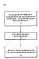
图7示出了用于制造定向性偏置的光发射器件的示例过程。FIG. 7 illustrates an example process for fabricating a directionally biased light-emitting device.
图8A到图8C图示了对光可调整液晶进行像素化的示例过程。8A-8C illustrate an example process of pixelating an optically adjustable liquid crystal.
图9A到图11A各自示出示例定向性偏置的光发射器件的透视图。9A-11A each illustrate a perspective view of an example directionally biased light-emitting device.
图9B 到图11B各自示出了图9A到图11A中示出的定向性偏置的光发射器件的截面视图。9B to 11B each show a cross-sectional view of the directionally biased light-emitting device shown in FIGS. 9A to 11A.
图12示出了堆叠的透明的光发射器件。Figure 12 shows stacked transparent light emitting devices.
图13示出了另一个堆叠的透明的光发射器件。Figure 13 shows another stacked transparent light emitting device.
具体实施方式Detailed ways
描述了从一侧或者主要从一侧发射辐射的透明的器件。具体地,将光学上活性的反射材料放置在透明的电致发光器件上,使得从该器件中的光发射层发射的辐射仅从该器件的一侧发出,或者主要从该器件的一侧发出,而同时环境光由该器件的两侧透射。该器件发射具有波长范围的手性辐射,并且光学上活性的反射材料的反射带调节成与从该器件发射的辐射的波长和螺旋性两者匹配,使得光学上活性的反射材料反射所发射的辐射。在这种方式中,透明的电致发光器件可以定向性偏置,使得所发射的辐射仅从该器件的一侧发出或者主要从该器件的一侧发出,而不是从该器件的两侧发出。Transparent components are described which emit radiation from one side or mainly from one side. Specifically, placing an optically active reflective material on a transparent electroluminescent device such that radiation emitted from a light emitting layer in the device is emitted from only one side of the device, or primarily from one side of the device , while ambient light is transmitted from both sides of the device. The device emits chiral radiation having a range of wavelengths, and the reflection band of the optically active reflective material is tuned to match both the wavelength and the helicity of the radiation emitted from the device such that the optically active reflective material reflects the emitted radiation. In this way, a transparent electroluminescent device can be directionally biased such that emitted radiation is emitted only or predominantly from one side of the device and not from both sides of the device .
公开的技术涉及有机发光二极管(OLED)技术的特定应用。具体地,公开的技术涉及利用了所发射的光的自旋极化和波长以获得单方向发射的透明的OLED(TOLED)。该器件透明,在于该器件从至少部分地对入射到材料上的辐射透射的一种或者多种材料制成。这样的TOLED可以称为透明有机单方向偏振的发光二极管(TOUPLED)。TOUPLED可以并入到或者覆盖在挡风玻璃上以例如允许驾驶员观看显示在挡风玻璃上的信息而该信息从挡风玻璃的其他侧不可见。因为TOUPLED对环境光透明,环境光通过挡风玻璃。相似地,TOUPLED技术可以利用在头盔上,具体地来说可以利用在军用作战头盔或者包括护目镜或者目镜的其他可视化工具上。用这样的布置,头盔的用户可以观看显示在护目镜一侧上的信息,而同时因为环境光进入护目镜,也能够透过护目镜观看。例如,TOUPLED可以装配在军用头盔的护目镜上,使得使用头盔的士兵可以观看显示在头盔护目镜的内部部分上的战术信息,而同时显示的战术信息从护目镜对着环境的一侧(即在其上装配光学上活性的反射层的一侧)不可见。然而,因为TOUPLED由对环境光至少部分地透明的材料制成,环境光继续通过护目镜。The disclosed technology relates to specific applications of organic light emitting diode (OLED) technology. In particular, the disclosed technology relates to transparent OLEDs (TOLEDs) that exploit the spin polarization and wavelength of emitted light to obtain unidirectional emission. The device is transparent in that the device is made from one or more materials that are at least partially transmissive to radiation incident on the material. Such TOLEDs may be referred to as transparent organic unidirectionally polarized light-emitting diodes (TOUPLEDs). The TOUPLED may be incorporated into or overlaid on the windshield to, for example, allow the driver to view information displayed on the windshield that is not visible from other sides of the windshield. Because TOUPLED is transparent to ambient light, ambient light passes through the windshield. Similarly, TOUPLED technology can be utilized on helmets, specifically military combat helmets or other visualization tools including visors or eyepieces. With this arrangement, the user of the helmet can view information displayed on one side of the goggle while also being able to see through the goggle as ambient light enters the goggle. For example, TOUPLED can be fitted on the visor of a military helmet, so that the soldier using the helmet can watch the tactical information displayed on the inner part of the helmet visor, while the displayed tactical information is from the side of the visor facing the environment (i.e. The side on which the optically active reflective layer is mounted) is not visible. However, because the TOUPLED is made of a material that is at least partially transparent to ambient light, ambient light continues to pass through the goggles.
参照图1,示出了定向性偏置的透明的光发射器件100的示例。光发射器件100包括光发射层1、光学上活性的反射层2以及透明衬底4。光发射层1布置在第一电极5和第二电极6之间。第一电极5可以是透明的阳极,而第二电极6可以是透明的阴极。第一电极5和第二电极6对从光发射层1发射的辐射的波长透明,以允许发射来自器件100的辐射。另外,第一电极5和第二电极6可以对环境光透明,使得环境光可以通过器件100。虽然在图1示出的示例中,第一电极5位于光发射层1的顶部7上,而第二电极6位于光发射层1的底部8上,在其他示例中,第一电极5和第二电极6可以布置成相反的配置。Referring to FIG. 1 , an example of a directionally biased transparent light emitting device 100 is shown. The light-emitting device 100 includes a light-emitting
当跨第一电极5和第二电极6施加正偏压时,阳极将空穴(正电荷载流子)注入到光发射层1中,并且阴极将电子(负电荷载流子)注入到光发射层1中。空穴和电子在光发射层1中复合,并且生成导致发光的激子。在这个方式中,光发射层1优选地以可见光的形式发射辐射。如以下将要更加详细论述的,从光发射层1发射的辐射具有波长和手征(例如辐射是圆偏振的,并且具有左旋方向或者右旋方向,或者辐射是椭圆偏振的并且具有左旋方向或者右旋方向)。When a positive bias voltage is applied across the
如以下将要更加详细论述的,光学上活性的反射层2通过将发射的辐射反射向光发射层1的顶部7并且进入在器件100的一侧上的光发射外壳9而阻挡从光发射层1发射的辐射。具体地,光学上活性的反射层2具有反射带,该反射带至少部分地包含从光发射层1发射的辐射的波长。光学上活性的反射层2的反射带是不由光学上活性的反射层2透射的波长带。另外,光学上活性的反射层2具有与从光发射层2发射的辐射的手征匹配的手征。As will be discussed in more detail below, the optically active
光学上活性的反射层2可以考虑为与从光发射层2发射的辐射的波长和手征匹配。通过匹配手征和波长,可以调整或者在其他方面修改光学上活性的反射层2的折射率,使得从光发射层2发射的辐射的波长位于光学上活性的反射层2的反射带的中心处,并且光学上活性的反射层2反射具有螺旋性偏振的辐射。具有螺旋性偏振的辐射是椭圆偏振或者圆偏振的并且具有右旋或者左旋螺旋性或者手征的辐射。椭圆偏振或者圆偏振的电磁波中在朝着传播的方向观看时在与传播方向垂直的固定平面中观察到的电场向量以左旋方向即逆时针方向旋转,并且传播的方向与当左旋螺杆拧入固定的螺母时左旋螺杆的前进方向相同。The optically active
在一些实施方式中,匹配手征和波长可以包括调整光学上活性的反射层2的折射率,使得光学上活性的反射层2具有包括从光发射层2发射的辐射的波长的至少一部分的光谱反射带。在这些实施方式中,光学上活性的反射层2可以具有反射带,该反射带位于发射的辐射的发射带的中心处,但是并不必须是这种情况。In some embodiments, matching the chirality and wavelength can include adjusting the refractive index of the optically active
光学上活性的反射层2还可以称为光学上活性的阻挡层或者光学上活性的滤光层。在图1中示出的示例中,从光发射层1发射的辐射通过顶部7离开定向性偏置的透明的光发射器件100,而不是通过光发射层1器件的底部8。然而,在其他示例中,光学上活性的反射层2可以位于光发射层1的顶部7的一侧上,使得从光发射层1发射的辐射通过衬底4离开器件100。因此,器件100可以是顶部发射透明器件或者底部发射透明器件。The optically active
在一种实施方式中,透明的光发射器件100是透明的有机单方向偏振光发射器件(TOUPLED)。在这个实施方式中,第一电极5是透明的阳极,而光发射层1是基于手性有机分子的光发射层(也称为手性有机的光发射层)。如以下关于图5A和图5B论述的,TOUPLED也可以包括电子隧穿势垒层、自旋极化的阴极(也可以称为自旋阴极)、透明衬底4以及调整到发射的光的波长和手征的光学上活性滤光层(也可以称为光学上活性的反射层)。在一个示例中,光学上活性的反射层的手征可以是右旋的,使得从光发射器件发射的右旋圆偏振光由光学上活性的反射层2反射。在其他实施方式中,光发射层可以由发射具有手性组分(例如非线性偏振的光)的辐射的任何光发射材料制成,或者可以包括发射具有手性组分(例如非线性偏振的光)的辐射的任何光发射材料。In one embodiment, the transparent light emitting device 100 is a transparent organic unidirectionally polarized light emitting device (TOUPLED). In this embodiment, the
在另一个实施方式中,光发射层1可以是非手性发光体。非手性发光体是并不必然发射手性辐射的光发射体,但是可以配置成、结构化成或者布置成发射手性辐射。例如,在这个实施方式中,光发射层1可以是无机量子点发射体,并且量子点发射体可以布置成产生手性辐射的手性矩阵。在这些实施方式中,量子点发射体沉积为单个单层。将沉积量子点发射体沉积为单个单层可以帮助局部化,并且因此控制激子的形成和弛豫。In another embodiment, the
在其他实施方式中,可以使用透明并且不干涉发射的辐射和阻挡的辐射的手征的任何透明的OLED层。非光学上活性的材料,或者弱光学上活性的材料并不将偏振赋予穿过该材料的辐射。因此,这样的材料可以作为透明的OLED层使用。可以作为透明的OLED层而使用的材料包括玻璃和ITO。在使用自旋注入体的实施方式中,可以使用最小化与电荷自旋寿命与电荷自旋寿命时间或者发射的辐射和阻挡的辐射的手征的干涉的任何透明的OLED层。In other embodiments, any transparent OLED layer that is transparent and does not interfere with the chirality of emitted and blocked radiation can be used. An optically inactive material, or a weakly optically active material, does not impart polarization to radiation passing through the material. Therefore, such materials can be used as transparent OLED layers. Materials that can be used as transparent OLED layers include glass and ITO. In embodiments using spin injectors, any transparent OLED layer that minimizes interference with charge spin lifetime versus charge spin lifetime time or chirality of emitted and blocked radiation may be used.
参照图2,示出了定向性偏置的透明的光发射器件200的示例。光发射器件200包括光发射层201、光学上活性的反射层202、透明衬底204、第一电极205以及第二电极206。除了透明衬底204布置在光学上活性的反射层202和光发射层201之间之外,器件200可以与关于图1讨论的器件100相似。与器件100相似,器件200将偏振的辐射发射到在器件200的一侧上的发射外壳209中。Referring to FIG. 2 , an example of a directionally biased transparent light
图3示出了定向性偏置的光发射器件300的示例,该器件包括两个光阻挡层以及右旋光学上活性层310以及左旋光学上活性层320。器件300还包括光发射层330、透明衬底340、第一电极350以及第二电极365。如以下关于图5A和图5B详细地论述的,从光发射层330发射的辐射可以是手性辐射(例如圆偏振光或者椭圆偏振光)。依赖于光发射器件300的配置,手性辐射可以包括近似相等数量的具有右旋螺旋性的手性光和具有左旋螺旋性的手性光,或者发射的手性辐射可以主要包括具有右旋螺旋性的手性光或者主要包括具有左旋螺旋性的手性光。FIG. 3 shows an example of a directionally biased
在图3中示出的示例中,光发射层330发射包括具有左旋螺旋性的手性光和具有右旋螺旋性的手性光的辐射。具有右旋螺旋性的手性光355从光学上活性层310反射,而具有左旋螺旋性的手性光360从光学上活性层320反射。因此,从光发射层330的底部370发射的辐射被反射通过器件300的顶部380,而不是通过底部370和顶部380两者离开器件。因为螺旋偏振光的手征在反射离开光学上活性的材料后保持方向,而在反射离开非光学上活性的材料后逆转方向,所以手性光360被反射为具有左旋螺旋性的光,而手性光355被反射为具有右旋螺旋性的光。In the example shown in FIG. 3 , the
参看图4A和图4B,示出了包括一个光学上活性的反射层405的、定向性偏置的光发射器件400的示例。器件400包括形成在衬底420上的光发射层410。光发射层410发射圆偏振并且具有右旋螺旋性的辐射440。如关于图5A和图5B论述的,从光发射层410发射的辐射的螺旋性可以通过例如在光发射层410中引入自旋向上的电子的族群来控制。如图4A中的示例中示出的,从光发射层410发射的辐射440具有右旋螺旋性,其从光学上活性的反射层405反射并且从器件400的顶部450发射。光学上活性的反射层405具有反射带,该反射带具有右旋手征,并且因此由于辐射440是具有右旋螺旋性的手性光,光学上活性层405反射辐射440。Referring to Figures 4A and 4B, an example of a directionally biased
参照图4B,示出了在出现具有左旋螺旋性和右旋螺旋性的圆偏振光时器件400的行为。具有右旋螺旋性的圆偏振辐射460从器件400发出,并且由于圆偏振辐射460具有右旋螺旋性,圆偏振辐射460从光学上活性的反射层405反射。偏振辐射470也从光学上活性的反射层405反射,这是因为层405的反射带的手性也是右旋的。辐射470也反射离开物体465,在反射后方向改变到具有左旋螺旋性的辐射480。因为辐射480具有左旋螺旋性,光学上活性的层405的反射带的手征与辐射480的手征不匹配。因此辐射480通过光学上活性的反射层405。Referring to Figure 4B, the behavior of
如以上论述的,TOUPLED可以包括阳极、有机的光发射层、阴极、衬底以及光学上活性的光阻挡层中的一个或者多个。在一些实施方式中,TOUPLED还可以包括电子输运层(ETL)、电子隧穿势垒层(TBL)以及空穴输运层(HTL)中的一个或者多个。在一些实施方式中,某些材料/物质可以作为以上描述和这里描述的一个分立元素而起作用,或者可以作为以上描述和这里描述的多个元素而起作用。例如,特定的材料/物质可以使用作为阳极并且具有空穴输运层的某些特性。As discussed above, a TOUPLED may include one or more of an anode, an organic light emitting layer, a cathode, a substrate, and an optically active light blocking layer. In some embodiments, the TOUPLED may further include one or more of an electron transport layer (ETL), an electron tunneling barrier layer (TBL), and a hole transport layer (HTL). In some embodiments, certain materials/substances may function as a discrete element or as multiple elements described above and herein. For example, certain materials/substances can be used as an anode and have certain properties of a hole transport layer.
参照图5A和图5B,示出了包括有机发光二极管(OLED)堆叠的、定向性偏置的光发射器件500A和光发射器件500B的示例。参照图5A,器件500A包括OLED堆叠20、衬底24、右旋光学上活性的反射层28以及左旋光学上活性的反射层29。OLED堆叠20包括阴极21、电子隧穿势垒层27、电子输运层25、光发射层22、空穴输运层26以及阳极23。阳极23与衬底24相邻。参见图5B,器件500B包括OLED堆叠30、衬底34以及光学上活性的反射层38。TOUPLED的OLED堆叠30可以包括阴极31、电子隧穿势垒层37、电子输运层(ETL)35、光发射层32、空穴输运层36以及阳极33。阳极33与衬底34相邻。Referring to FIGS. 5A and 5B , examples of a directionally biased light-emitting
定向性偏置的光发射器件500A和光发射器件500B可以是TOUPLED。TOUPLED可以考虑为连续地沉积在衬底上的一系列相邻的层。衬底可以是以上论述的衬底4、衬底204、衬底340、衬底24或者衬底34。用于在衬底上沉积层的技术包括例如化学气相沉积、物理气相沉积、溅射、热蒸发、电子束沉积、真空沉积、旋转涂覆以及喷墨式打印机技术的修改。用于在衬底上沉积层的技术也可以用来在已经沉积的层中引入或者“掺杂”另外的化合物。例如,在TOUPLED的制造期间,可以沉积电子输运层(ETL)(例如关于图5A和图5B论述的电子输运层25或者电子输运层35)并且通过将ETL沉积在超薄锂层上或者将超薄锂层沉积在ETL上来用金属对ETL进行掺杂。基于在这个方式中准备的层的厚度,锂可以从任何方向全部地扩散遍及ETL,因此形成退化地掺杂的ETL。锂层也可以沉积在ETL的两侧上,或者锂可以与ETL共同沉积。锂层可以沉积成使得层大约0.5nm到1.0nm厚。The directionally biased light-emitting
在其上制造TOUPLED的衬底是对从TOUPLED发射的辐射的波长和手征透明的材料。例如,衬底可以是玻璃和/或者塑料。由例如以下制成的聚合物膜可以作为塑料衬底使用:聚氯乙烯(PVC)、聚酯(PET)、聚醚砜(PES)、聚萘二甲酸乙二醇酯(PEN)、聚碳酸酯(PC)、尼龙、聚醚醚酮(PEEK)、聚砜(PSF)、聚醚酰亚胶(PEI)、聚芳酯(PAR)以及聚对苯二甲酸丁二醇酯(PBT)。The substrate on which the TOUPLED is fabricated is a material transparent to the wavelength and chirality of the radiation emitted from the TOUPLED. For example, the substrate can be glass and/or plastic. Polymer films made of, for example, polyvinyl chloride (PVC), polyester (PET), polyethersulfone (PES), polyethylene naphthalate (PEN), polycarbonate Polyester (PC), Nylon, Polyetheretherketone (PEEK), Polysulfone (PSF), Polyether Acetylene (PEI), Polyarylate (PAR) and Polybutylene Terephthalate (PBT).
TOUPLED可以包括阳极,该阳极将带正电荷的载流子(“空穴”)注入到光发射层中。在一些实施方式中,如以上提到的,依赖于用作为阳极的材料/物质的特定类型,阳极还可以将空穴输运到光发射层中。阳极可以由例如透明的氧化铟锡(ITO)或者In2O3:SnO2制成。阳极例如可以是分别关于图5A和图5B论述的阳极23或者阳极33。光发射层可以是光发射层22或者光发射层32。TOUPLEDs may include an anode that injects positively charged charge carriers ("holes") into the light emitting layer. In some embodiments, as mentioned above, depending on the particular type of material/substance used as the anode, the anode can also transport holes into the light emitting layer. The anode can be made of, for example, transparent indium tin oxide (ITO) or In2 O3 :SnO2 . The anode may be, for example, the anode 23 or the anode 33 discussed with respect to FIGS. 5A and 5B , respectively. The light-emitting layer may be light-emitting layer 22 or light-emitting layer 32 .
TOUPLED也包括阴极,例如阴极21或者阴极31。阴极将带负电荷的载流子或者电子注入到光发射层中。在一些实施方式中,依赖于用作为阴极的材料/物质的特定类型,阴极也可以将电子输运到光发射层中。阴极层可以使用例如直流溅射/圆柱靶材沉积来进行沉积。ITO和氧化铟锌(IZO)是用于在制造透明的阴极层中使用的导电材料的两个示例。后续的阴极层可以包括透明的材料、金属材料或者非金属材料,并且帮助改善发射器件的量子效率、电子注入、最小化功函数以及作为便于ITO在预沉积的有机层上的沉积的保护缓冲层;透明的金属掺杂的阴极层也可以作为激子阻挡层和/或者空穴阻挡层而起作用;或者透明的、金属或者非金属的阴极层,接下来是由对于向上和向下电子自旋具有不同导电性的材料制成的电子选择性层。用于在透明的阴极中使用以便于电子输运和注入的适当的材料可以包括但是不限于以下:氟化锂(LiF)、铝(Al)、锂掺杂的铝、(Li:Al)、镁掺杂的银(Mg:Ag)、浴铜灵(BCP)(2,9-二甲基-4,7-二苯基-1,10-菲罗啉)、碳酸铯(CsCO3)、锂掺杂的浴铜灵(LiBCP)或者铯掺杂的phenyldipyrenylphosphine oxide(CsPOPy2)。TOUPLED also includes a cathode, such as cathode 21 or cathode 31 . The cathode injects negatively charged carriers, or electrons, into the light emitting layer. In some embodiments, depending on the particular type of material/substance used as the cathode, the cathode can also transport electrons into the light emitting layer. The cathode layer can be deposited using eg DC sputtering/cylindrical target deposition. ITO and Indium Zinc Oxide (IZO) are two examples of conductive materials for use in making the transparent cathode layer. Subsequent cathode layers can include transparent, metallic or non-metallic materials and help improve quantum efficiency of emissive devices, electron injection, minimize work function and act as a protective buffer layer to facilitate deposition of ITO on pre-deposited organic layers ; a transparent metal-doped cathode layer can also function as an exciton-blocking layer and/or a hole-blocking layer; An electron-selective layer made of materials with different conductivity. Suitable materials for use in transparent cathodes to facilitate electron transport and injection may include, but are not limited to, the following: lithium fluoride (LiF), aluminum (Al), lithium-doped aluminum, (Li:Al), Magnesium-doped silver (Mg:Ag), bathocuproine (BCP) (2,9-dimethyl-4,7-diphenyl-1,10-phenanthroline), cesium carbonate (CsCO3), lithium Doped bathocuproine (LiBCP) or cesium-doped phenyldipyrenylphosphine oxide (CsPOPy2 ).
为了控制从TOUPLED发射的手性光的螺旋性,与具有自旋向下量子自旋状态的电子族群相比,具有自旋向上量子自旋状态的电子族群可以被控制。电子存在于两种量子自旋状态中,自旋向上或者自旋向下,其与相反符号的相等单位的角动量值相关联。正常分布的电子的族群是包含相等数量的在自旋向上状态中的电子和在自旋向下状态中的电子的混合物。当在有机的光发射分子层中正常分布的电子族群与空穴复合时,产生手性光(例如圆偏振光和/或者椭圆偏振光)。发射的光近似地是具有右旋螺旋性(RH)的光与具有左旋螺旋性(LH)的光的均等混合物。To control the helicity of chiral light emitted from TOUPLEDs, the population of electrons with a spin-up quantum spin state can be controlled compared to the electron population with a spin-down quantum spin state. Electrons exist in two quantum spin states, spin up or spin down, which are associated with angular momentum values of equal units of opposite signs. A population of normally distributed electrons is a mixture containing equal numbers of electrons in the spin-up state and electrons in the spin-down state. Chiral light (eg, circularly polarized light and/or elliptically polarized light) is produced when a population of electrons normally distributed in an organic layer of light-emitting molecules recombines with holes. The emitted light is approximately an equal mixture of light with right-handed helicity (RH) and light with left-handed helicity (LH).
然而,在一些实施方式中,TOUPLED可以利用在单个自旋状态的电子。当在TOUPLED中单个自旋状态的电子与空穴复合时,由于量子自旋选择规则,发射的手性光相对于发射体分子方向具有单个手性(螺旋性)。发射的光的螺旋性是相对于发射体分子的磁力校准的轴测量的并且符号是注入的电子和空穴的自旋状态的函数。例如,当在自旋向上状态的电子与空穴复合时,相对于取向磁场具有右旋螺旋性的手性光在向前的方向上发射。当在自旋向下状态中的电子与空穴复合时,相对于取向磁场具有左旋螺旋性的手性光在向前的方向上发射。However, in some embodiments, TOUPLEDs can utilize electrons in a single spin state. When electrons in a single spin state recombine with holes in a TOUPLED, the emitted chiral light has a single chirality (helicity) relative to the emitter molecular orientation due to the quantum spin selection rule. The helicity of the emitted light is measured relative to the magnetically aligned axis of the emitter molecule and the sign is a function of the spin states of the injected electrons and holes. For example, when electrons in a spin-up state recombine with holes, chiral light having right-handed helicity with respect to an orientation magnetic field is emitted in a forward direction. When electrons in the spin-down state recombine with holes, chiral light having left-handed helicity with respect to the orientation magnetic field is emitted in the forward direction.
自旋极化的电子可以通过例如经由隧穿的自旋筛选和经由磁化的注入体的自旋极化来产生。经由隧穿的自旋筛选利用位于靠近阴极或者夹在两个电子输运层之间的电子隧穿势垒层(TBL),两个电子输运层中的一个与阴极相邻。在自旋向上状态的电子与在自旋向下状态的电子相比具有更大的动量。在自旋向上状态的电子的较大动量允许这些电子隧穿通过TBL,而在自旋向下状态的电子不能够通过TBL。因此,TBL用在自旋向上状态的电子丰富了在光发射层中流动的电流。在光发射层中自旋向上电子的族群与空穴辐射性复合,并且因此光发射层发射具有右旋螺旋性的手性光。自旋隧穿筛选可以产生具有接近100%的向上自旋电子的电子族群。因此,发射的辐射是接近100%右旋偏振辐射。TBL可以由例如EuxOy(x>>y)制成,选择它是由于其能够参与到在导带中的大交换分裂的能力(在0.6eV量级),并且由于它的高度透明性。也可以使用具有高度透明性并且能够参与到交换分裂中的其他材料,例如一氧化镁和ITO。依赖于电子的自旋状态,电子携带不同的磁动量。一些材料参与到交换分裂中,并且在这些材料中,在自旋向上状态中的电子(与在自旋向下状态中的电子相比具有较高的动量)具有隧穿通过该材料的较大概率。交换分裂越大,材料在自旋向上和自旋向下电子之间区别得越有效。因此,在具有相对大交换分裂的材料中,自旋向上的电子具有隧穿通过该材料的较大概率,并且结果更多自旋向上的电子通过。结果,生成了自旋极化的电流。Spin-polarized electrons can be generated by, for example, spin screening via tunneling and spin polarization via magnetized injectors. Spin screening via tunneling utilizes an electron tunneling barrier layer (TBL) located close to the cathode or sandwiched between two electron transport layers, one of which is adjacent to the cathode. Electrons in the spin-up state have greater momentum than electrons in the spin-down state. The greater momentum of electrons in the spin-up state allows these electrons to tunnel through the TBL, while electrons in the spin-down state are unable to pass through the TBL. Thus, the TBL enriches the current flowing in the light-emitting layer with electrons in the spin-up state. A population of spin-up electrons radiatively recombines with holes in the light-emitting layer, and thus the light-emitting layer emits chiral light with right-handed helicity. Spin tunneling screening can generate electron populations with nearly 100% spin-up electrons. Thus, the emitted radiation is nearly 100% right-handed polarized radiation. TBL can be made of e.g. Eux Oy (x >> y), which is chosen for its ability to participate in large exchange splitting in the conduction band (on the order of 0.6eV), and for its high transparency . Other materials that are highly transparent and able to participate in exchange splitting can also be used, such as magnesium monoxide and ITO. Depending on the spin state of the electrons, the electrons carry different magnetic momenta. Some materials participate in exchange splitting, and in these materials, electrons in the spin-up state (which have higher momentum compared to electrons in the spin-down state) have a greater probability. The greater the exchange split, the more effectively the material discriminates between spin-up and spin-down electrons. Thus, in a material with a relatively large exchange splitting, spin-up electrons have a greater probability of tunneling through the material, and more spin-up electrons pass as a result. As a result, a spin-polarized current is generated.
在一些实施方式中,在自旋向上状态的电子可以经由磁化的注入体产生。磁电子注入阴极(例如铬掺杂的氧化铟锡)形成注入到光发射层的、自旋向上极化的电子。在自旋向上状态中的电子与空穴的辐射复合引起具有右旋螺旋性的手性光的发射。电子自旋选择性阴极可以例如由以下制成:铬掺杂的氧化铟锡(Cr:ITO);铬掺杂的氧化铟(Cr:IO);任何透明的半金属(用K2S掺杂(大约5%掺杂)的Mo、Zr、Nb、Ru以及Tc);用K2O掺杂(大约5%掺杂)的Zr,Tc和Ru;或者用K2Se、K2Te或者Rb2S掺杂的Zr、Nb和Ru;任何透明的霍伊斯勒合金;来自称为是半金属性的一类材料并且具有分子式X2YZ(其中X和Y是过渡元素,即在周期表上的IB族到VIIIB族,并且Z是III族、IV族或者V族元素)的任何化合物。In some embodiments, electrons in the spin-up state can be generated via magnetized injectors. Magnetic electron injection into the cathode (eg, chromium-doped indium tin oxide) forms spin-up polarized electrons that are injected into the light-emitting layer. The radiative recombination of electrons and holes in the spin-up state causes the emission of chiral light with right-handed helicity. Electron spin-selective cathodes can be made, for example, of: chromium-doped indium tin oxide (Cr:ITO); chromium-doped indium oxide (Cr:IO); any transparent semi-metal (doped withK2S (approximately 5% doped) of Mo, Zr, Nb, Ru, and Tc); withK2O doped (approximately 5% doped) of Zr, Tc, and Ru; or withK2Se ,K2Te , or Rb2 S-doped Zr, Nb, and Ru; any transparent Heusler alloy; from a class of materials known as semimetals and having the formula X2 YZ (where X and Y are transition elements, i.e. in the periodic table any compound of Groups IB through VIIIB above, and Z is a Group III, IV or V element.
在一些实施方式中,磁化的注入体可以与电子隧穿势垒层一起使用以在较高的环境温度下获得与单独自旋筛选或者单独磁化的注入体能获得的电流相比更纯净的自旋极化电流。磁化的注入体可以用来供应预自旋极化电流(例如自旋向上)到隧穿势垒,隧穿势垒接着滤除任何剩余的在自旋向下状态中的电子。在自旋向上状态中的极化电子也可以通过混合的自旋注入隧穿过滤器来产生。与空穴的电子对应物类似,空穴可考虑为存在于两种单独的量子自旋状态中。因此,单个螺旋性的手性光可以通过电子与自旋极化的空穴的辐射复合来产生。单个螺旋性的手性光也可以通过自旋极化的电子与自旋极化的空穴的辐射复合来产生。In some embodiments, magnetized implants can be used with electron tunneling barriers to obtain purer spins at higher ambient temperatures than can be obtained with spin screening alone or magnetized implants alone. Polarization current. A magnetized injector can be used to supply a pre-spin polarized current (eg, spin up) to the tunneling barrier, which then filters out any remaining electrons in the spin down state. Polarized electrons in the spin-up state can also be generated through mixed spin-injection tunneling filters. Similar to the electronic counterpart of a hole, a hole can be considered to exist in two separate quantum spin states. Thus, chiral light of a single helicity can be generated by the radiative recombination of electrons with spin-polarized holes. Chiral light of a single helicity can also be generated by the radiative recombination of spin-polarized electrons with spin-polarized holes.
图6A示出了包括有机发光二极管(OLED)堆叠的、定向性偏置的光发射器件的示例。在图6A中示出的示例器件600是包括透明的有机光发射层(OLEL)602的TOUPLED。OLEL 602包括阴极604、电子注入层606、电子输运层608、有机的光发射层610、空穴输运层612以及阳极614。光学上活性的反射层可以布置在堆叠的阴极或者阳极上。在图6A中示出的示例中,光学上活性的反射层630布置在阴极604上。Figure 6A shows an example of a directionally biased light-emitting device comprising an organic light emitting diode (OLED) stack. The example device 600 shown in FIG. 6A is a TOUPLED including a transparent organic light emitting layer (OLEL) 602 . The OLEL 602 includes a cathode 604, an electron injection layer 606, an electron transport layer 608, an organic light emitting layer 610, a hole transport layer 612, and an anode 614. An optically active reflective layer can be arranged on the stacked cathode or anode. In the example shown in FIG. 6A , an optically active reflective layer 630 is disposed on cathode 604 .
在图6A示出的示例中,阳极614包括为ITO和玻璃的导电阳极。ITO层近似为42纳米(42-nm)厚。光发射层602也包括由三氧化钼(MoO3)层制成的、大约20nm厚的层间电短路减少层613以及空穴输运层612,在这个示例中包括为N,N′-di(naphthalene-1-yl)-N,N′-diphenyl-benzidine(NPB)的层,该层大约55nm厚。光发射层610由Alq3+C6制成,并且大约60nm厚,并且电子输运层608大约40nm厚,并且由4,7-二苯基-1,10-菲罗啉(Bphen)制成。电子注入层606大约0.5nm厚,并且由氟化锂(LiF)制成。在图6A的示例中,阴极604包括ITO和铝(Al)。ITO层大约65nm厚,并且铝层大约100nm厚。铝层的出现允许可以溅射,或者通过其他方式而施加ITO到电子注入层606上。In the example shown in FIG. 6A, anode 614 includes a conductive anode that is ITO and glass. The ITO layer is approximately forty-two nanometers (42-nm) thick. The light emitting layer 602 also includes an approximately 20 nm thick interlayer electrical short reduction layer 613 made of molybdenum trioxide (MoO3 ) layer and a hole transport layer 612, comprised in this example as N,N′-di A layer of (naphthalene-1-yl)-N,N'-diphenyl-benzidine (NPB), which is about 55 nm thick. The light emitting layer 610 is made of Alq3+C6 and is about 60 nm thick, and the electron transport layer 608 is about 40 nm thick and is made of 4,7-diphenyl-1,10-phenanthroline (Bphen). The electron injection layer 606 is about 0.5 nm thick and made of lithium fluoride (LiF). In the example of FIG. 6A, cathode 604 includes ITO and aluminum (Al). The ITO layer is about 65nm thick and the aluminum layer is about 100nm thick. The presence of the aluminum layer allows ITO to be sputtered, or otherwise applied, onto the electron injection layer 606 .
在另一实施方式中,阴极可以包括为ITO和玻璃的导电阴极、碳酸铯(CsCO3)电子注入层、为Bphen的电子输运层,为Alq3+C6的光发射层、MoO3和NPB的空穴输运层以及为银(Ag)和ITO的阳极。阳极的银部分可以是光可以通过的银薄层,并且银作为允许ITO溅射到空穴输运层上的保护性层而起作用。In another embodiment, the cathode may include a conductive cathode of ITO and glass, an electron injection layer of cesium carbonate (CsCO3), an electron transport layer of Bphen, a light emitting layer of Alq3+C6, a void ofMoO3 and NPB. The hole transport layer and the anode are silver (Ag) and ITO. The silver portion of the anode can be a thin layer of silver through which light can pass, and the silver acts as a protective layer allowing the ITO to be sputtered onto the hole transport layer.
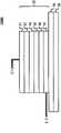
器件600还包括光学上活性的反射层630。光学上活性的反射层630包括玻璃层632以及大约30nm到40nm厚并且水平地抛光的取向涂层634。取向涂层634层布置在右旋GLC 636的两侧上,GLC 636大约8-μm厚,并且玻璃层638布置在GLC层636的相对侧上。折射率匹配粘合剂层640布置在玻璃层638上,并且竖直地抛光并且大约30nm到40nm厚的取向涂层646布置在大约8μm厚的左旋GLC 648的两侧上。玻璃层652和折射率匹配粘合剂层654也包括在光学上活性的反射层630中。在图6A示出的示例中,右旋GLC和左旋GLC两者都调整为具有大约75nm宽并且中心在525nm的反射带。Device 600 also includes an optically active reflective layer 630 . The optically active reflective layer 630 includes a glass layer 632 and an orientation coating 634 approximately 30 nm to 40 nm thick and horizontally polished. An orientation coating 634 layer is disposed on both sides of a right-handed GLC 636 that is about 8-μm thick, and a glass layer 638 is disposed on the opposite side of the GLC layer 636. An index matching adhesive layer 640 is disposed on the glass layer 638, and a vertically polished and approximately 30 nm to 40 nm thick alignment coating 646 is disposed on both sides of a left-handed GLC 648 approximately 8 μm thick. A glass layer 652 and an index matching adhesive layer 654 are also included in the optically active reflective layer 630 . In the example shown in FIG. 6A, both right-handed and left-handed GLCs are tuned to have reflection bands approximately 75 nm wide and centered at 525 nm.
在这些实施方式的两者之任一中,光学上活性层630可以与阴极604或者阳极614相邻。在图6A的示例中,光学上活性层630与阴极604相邻并且来自器件600的定向性偏置的光从器件的底部650发射。In either of these embodiments, the optically active layer 630 can be adjacent to either the cathode 604 or the anode 614 . In the example of FIG. 6A , optically active layer 630 is adjacent to cathode 604 and directionally biased light from device 600 is emitted from bottom 650 of the device.
层的厚度可以是除了在图6A中的示例中指定的以外的其他值。在一些实施方式中,空穴输运层612可以在5nm和100nm之间的厚度,有机的光发射层610可以具有在10nm到几百纳米之间的厚度,电子输运层608可以具有10nm到几百纳米之间的厚度并且薄金属电子注入层606(在图6A的示例中是铝)可以具有在10nm到几百纳米之间的厚度。The thickness of the layers may be other values than specified in the example in FIG. 6A. In some embodiments, the hole transport layer 612 can have a thickness between 5 nm and 100 nm, the organic light-emitting layer 610 can have a thickness between 10 nm and several hundred nanometers, and the electron transport layer 608 can have a thickness between 10 nm and 100 nm. The thickness is between a few hundred nanometers and the thin metal electron injection layer 606 (aluminum in the example of FIG. 6A ) may have a thickness between 10 nm and several hundred nanometers.
图6B图示了在图6A中示出的器件600的发射特性。发射特性包括曲线690和曲线695,每个表示作为从器件600发射的辐射的波长的函数的强度。曲线690示出来自器件600的底部的发射,并且曲线695示出来自器件600的顶部的发射。如图6B中看到的,器件600定向性偏置使得来自器件600的底部的发射强度大于来自器件600的顶部的发射。来自器件600的顶部的发射主要由从器件600的泄露引起。然而,来自器件600的底部的发射由来自光发射层602的光反射离开光学上活性的层630而引起。因此,来自器件600的底部的发射在强度上显著地大于来自器件600的顶部的发射,并且由于包括在光学上活性的层630中的GLC层636和648的反射带的调整,来自器件600的底部的发射以大约525nm的波长为中心。FIG. 6B illustrates the emission characteristics of the device 600 shown in FIG. 6A. The emission characteristic includes
在一些实施方式中,TOUPLED还可以包括布置在阴极和阳极之间的附加的层,每个层具有不同的组成并且执行不同的功能。这样的材料应当由于它们的电荷迁移率特性而选择,以在那里期望不受限制的电荷输运的连续的层界面之间生成平滑的能量级转换(电离势),或者在期望电荷载流子复合的局部化的地方生成能量势垒。材料可以是小分子或者聚合物。例如,TOUPLED可以包括电子输运层(ETL),例如电子输运层35。ETL可以有效地跨层表面分散负电荷载流子(电子)的注入电流,并且ETL在ETL和ETL的与阴极相对的一侧上的层的边界处提供均匀电流。ETL还可以作为正电荷载流子(空穴)阻挡层起作用以提升在光发射层中的电荷载流子复合的可能性和局部化。自旋极化电子输运层可以改善注入电子的自旋极化状态被保留的概率。适当的ETL材料包括但是不限于4,7-二苯基-1,10-菲罗啉(Bphen)、2,9-二甲基-4,7-二苯基-1,10-菲罗啉(BCP)或者三(8-羟基喹啉)铝(Alq3)。In some embodiments, the TOUPLED may also include additional layers disposed between the cathode and the anode, each layer having a different composition and performing a different function. Such materials should be selected due to their charge mobility properties to generate smooth energy level transitions (ionization potentials) between successive layer interfaces where unrestricted charge transport is desired, or where charge carrier The localized localization of the compound generates energy barriers. Materials can be small molecules or polymers. For example, TOUPLED may include an electron transport layer (ETL), such as electron transport layer 35 . The ETL can effectively disperse the injected current of negative charge carriers (electrons) across the layer surface, and the ETL provides a uniform current at the boundary of the ETL and the layer on the side of the ETL opposite the cathode. The ETL can also function as a positive charge carrier (hole) blocking layer to enhance the probability and localization of charge carrier recombination in the light emitting layer. The spin-polarized electron transport layer can improve the probability that the spin-polarized state of injected electrons is preserved. Suitable ETL materials include, but are not limited to, 4,7-diphenyl-1,10-phenanthroline (Bphen), 2,9-dimethyl-4,7-diphenyl-1,10-phenanthroline (BCP) or tris(8-quinolinolato)aluminum (Alq3 ).
在另一些实施方式中,可以提供空穴输运层(HTL)(例如空穴输运层36)以有效地跨HTL分散正电荷载流子(空穴),使得将均匀电流(空穴)提供到与HTL相邻的层的表面,该层可以是光发射层。HTL还可以作为负电荷载流子(电子)阻挡层起作用,以提升在光发射层中的载流子复合的可能性和局部化。可以连续地使用一个或者多个HTL层。HTL可以由包括但是不限于以下的大量材料制成:N,N′-di(naphthalene-1-yl)-N,N′-diphenyl-benzidine(NPB)或者4,4’-bis[N(1-naphyl)-N-phenylamino]biphenyl(α-NPD)(NPD)、1,3,5-Tris(diphenylamino)benzene 97%(TDAB),或者由诸如以4,4’,4”-三[2-萘基(苯基)氨基]三苯基胺(2-TNATA)作为小分子示例或者以聚(2-乙烯基萘)作为聚合物示例的TDATA族制成。可以将掺杂剂材料添加到HTL中以改善器件的寿命和效率。例如,NPB可以用三氧化钼(MoO3)掺杂以降低空穴注入势垒,改善界面稳定性,以及抑制HTL的结晶化。In other embodiments, a hole transport layer (HTL) such as hole transport layer 36 may be provided to effectively disperse positive charge carriers (holes) across the HTL such that a uniform current (hole) Provided to the surface of a layer adjacent to the HTL, this layer may be a light emitting layer. HTL can also function as a negative charge carrier (electron) blocking layer to enhance the probability and localization of carrier recombination in the light emitting layer. One or more HTL layers can be used consecutively. HTLs can be made from a number of materials including, but not limited to: N,N'-di(naphthalene-1-yl)-N,N'-diphenyl-benzidine (NPB) or 4,4'-bis[N(1 -naphyl)-N-phenylamino]biphenyl(α-NPD)(NPD), 1,3,5-Tris(diphenylamino)benzene 97% (TDAB), or by such as 4,4',4"-three [2 -Naphthyl(phenyl)amino]triphenylamine (2-TNATA) as a small molecule example or made from the TDATA family with poly(2-vinylnaphthalene) as a polymer example. Dopant materials can be added to In HTL to improve device lifetime and efficiency. For example, NPB can be doped with molybdenum trioxide (MoO3 ) to lower the hole injection barrier, improve interface stability, and inhibit crystallization of HTL.
在一些实施方式中,作为ETL或者HTL起作用的材料/物质可以包括并入到光发射层以产生电致发光发射的相同材料。如果HTL或者ETL作为这样的器件的发射层(例如,光发射层)起作用,那么TOUPLED可以称为具有单个异质结构。替代地,具有包括在HTL和ETL之间的单独电致发光材料层的TOUPLED可以称为具有双重异质结构。因此,用于产生电致发光的异质结构可以制造为单个异质结构或者双重异质结构。In some embodiments, materials/substances that function as ETLs or HTLs may include the same materials that are incorporated into the light-emitting layer to produce electroluminescent emissions. A TOUPLED can be said to have a single heterostructure if the HTL or ETL functions as the emissive layer (eg, light-emitting layer) of such a device. Alternatively, a TOUPLED with a separate layer of electroluminescent material included between the HTL and the ETL can be said to have a double heterostructure. Thus, heterostructures for generating electroluminescence can be fabricated as single heterostructures or as double heterostructures.
在一些实施方式中,可以在连续的层之间插入一个或者多个缓冲层以降低连续的层的功函数之间的突变差别势垒高度。In some embodiments, one or more buffer layers may be inserted between successive layers to reduce the abrupt difference barrier height between the work functions of successive layers.
光发射层的材料特性决定了从OLED发射的辐射的波长,并且因此决定了颜色。通过为具有诸如香豆素6(C6)的材料的光发射层选择不同的有机固体,或者通过对用来制成光发射层的有机固体进行掺杂,发射的辐射的颜色可以变化。在一些实施方式中,单个的TOUPLED堆叠包括光发射层,该光发射层发射特定颜色的光,并且在另一些实施方式中,TOUPLED包括多个光发射层,每个光发射层发射不同颜色的光。应当选择具有窄带发射(饱和颜色)的TOUPLED光发射材料。用于光发射层的适当材料包括但是不限于以下:作为小分子示例的三(1,10-菲罗啉)钌(II)氯化物水合物、三(8-羟基喹啉)铝(Alq3)、二(8-羟基喹啉)锌(Znq)或者作为聚合物示例的聚(9,9-双(2-乙基己基)-9H-芴-2,7-次亚乙烯基)。The material properties of the light emitting layer determine the wavelength of the radiation emitted from the OLED, and thus the color. By choosing different organic solids for the light-emitting layer with materials such as Coumarin 6 (C6), or by doping the organic solids used to make the light-emitting layer, the color of the emitted radiation can be varied. In some embodiments, a single TOUPLED stack includes a light-emitting layer that emits light of a particular color, and in other embodiments, a TOUPLED includes multiple light-emitting layers that each emit light of a different color. Light. TOUPLED light-emitting materials should be selected with narrow-band emission (saturated color). Suitable materials for the light-emitting layer include, but are not limited to, the following: Tris(1,10-phenanthroline)ruthenium(II) chloride hydrate, tris(8-quinolinolato)aluminum (Alq3) as examples of small molecules , bis(8-hydroxyquinoline)zinc (Znq) or poly(9,9-bis(2-ethylhexyl)-9H-fluorene-2,7-vinylidene) as an example of a polymer.
另外,在一些实施方式中,由有机的光发射层(OLEL)发射的辐射的波长可以通过添加荧光和/或磷光材料来修改,该荧光和/或磷光材料吸收由光发射层发射的光并且再发射较长波长的辐射。在一些实施方式中,发射的辐射的颜色可以通过在TOUPLED和观察者之间放置彩色膜或者荧光膜来改变。Additionally, in some embodiments, the wavelength of radiation emitted by the organic light-emitting layer (OLEL) can be modified by adding fluorescent and/or phosphorescent materials that absorb light emitted by the light-emitting layer and emit longer wavelength radiation. In some embodiments, the color of the emitted radiation can be changed by placing a colored or fluorescent film between the TOUPLED and the observer.
TOUPLED还包括光学上活性的反射层,例如光学上活性的反射层2、光学上活性的反射层202、光学上活性的反射层405和光学上活性的反射层420、光学上活性的反射层28和光学上活性的反射层29,或者光学上活性的反射层38。光学上活性的反射区域可以是光学上活性的手性光阻挡层(OA-LBL)。适合于使用为OA-LBL的材料包括,例如双色材料、包括不对称碳原子的有机的化合物、和来自诸如形成玻璃的手性向列型液晶(GLC)以及手性电介质雕塑薄膜波长选择性反射器之类的无机化合物。另外,作为OA-LBL起作用的层可以使用与使用来沉积TOUPLED的其他层的方法类似的方法进行沉积。使用涉及在制造工艺期间控制在其上制造薄膜的衬底的运动的技术来制造雕塑薄膜。雕塑薄膜的制造涉及在沉积工艺期间关于两个轴旋转衬底的计算机化的控制。TOUPLED also includes optically active reflective layers, such as optically active
在一个实施方式中,OA-LBL可以包括GLC层,GLC层是包括准向列型液晶层的螺旋性堆叠的胆甾型薄膜。GLC膜的光学特性很大程度上由手征(即左旋或者右旋)和螺距长度决定。GLC膜的手征由累积的向列型液晶指向矢旋扭的旋转方向决定,该旋扭源自每个连续的准向列型液晶层关于膜的预期光学轴的旋转。螺距长度是完成光学指向矢360度旋转所需的距离。胆甾型液晶膜可以由准气动层的螺旋性的堆叠而制成,并且手偏性(右手偏性或者左手偏性)描述从一个层到另一个层向列型指向矢的旋扭发生的方向。螺距长度是沿着辐射的传播方向上通过层距离,在该距离上指向矢旋转了360°。In one embodiment, the OA-LBL may include a GLC layer, which is a helically stacked cholesteric film including a quasi-nematic liquid crystal layer. The optical properties of GLC films are largely determined by chirality (ie, left-handed or right-handed) and pitch length. The chirality of a GLC film is determined by the direction of rotation of the cumulative nematic liquid crystal director twist resulting from the rotation of each successive quasi-nematic liquid crystal layer about the expected optical axis of the film. The pitch length is the distance required to complete a 360 degree rotation of the optical director. Cholesteric liquid crystal films can be made from a helical stack of quasi-pneumatic layers, and handedness (right-handed or left-handed) describes how the twisting of the nematic director from one layer to the other occurs. direction. The pitch length is the distance through the layer along the direction of propagation of the radiation over which the director is rotated by 360°.
胆甾型液晶可以从已经用非常低浓度的手性掺杂剂进行了掺杂的向列型液晶得到,并且胆甾相的胆甾型液晶螺距对手性掺杂剂的结构修改敏感。因此,初始螺距主要由特定手性掺杂剂的选择决定,并且GLC层的反射带可以通过选择特定掺杂剂分子而不必在GLC层上执行后续的光调制而设定。GLC膜选择性地反射给定波长的能力由螺距长度和准向列型层的非常折射率和正常的折射率之间的关系支配。这些非常折射率和正常折射率之间的差别决定了GLC膜的整体的光学双折射,这反过来决定选择性反射波长带的宽度。与这个选择性反射带相关联的波长可以通过修改GLC的化学组成而改变。另外地或者替代地,反射带可以通过例如GLC膜的光调制或者改变或者调节GLC膜的分子比率而调整。在一些实施方式中,反射带可以通过使用光调制和分子比率的调节两者来调节,例如通过调节在GLC膜中的材料的分子比率并且然后对该GLC膜进行光调制。Cholesteric liquid crystals can be obtained from nematic liquid crystals that have been doped with very low concentrations of chiral dopants, and the cholesteric liquid crystal pitch of the cholesteric phase is sensitive to the structural modification of chiral dopants. Thus, the initial pitch is mainly determined by the choice of specific chiral dopants, and the reflection band of the GLC layer can be set by selecting specific dopant molecules without having to perform subsequent light modulation on the GLC layer. The ability of a GLC film to selectively reflect a given wavelength is governed by the relationship between the pitch length and the extraordinary and normal indices of refraction of the quasi-nematic layer. The difference between these extraordinary and ordinary refractive indices determines the overall optical birefringence of the GLC film, which in turn determines the width of the selectively reflective wavelength band. The wavelength associated with this selective reflection band can be altered by modifying the chemical composition of the GLC. Additionally or alternatively, the reflection band may be tuned by, for example, light modulation of the GLC film or changing or adjusting the molecular ratio of the GLC film. In some embodiments, the reflection band can be tuned by using both light modulation and modulation of molecular ratios, for example by adjusting the molecular ratios of materials in a GLC film and then light modulating the GLC film.
在一些实施方式中,GLC层的反射带可以考虑为作为光学陷波滤光器起作用,该滤光器具有通过调节GLC膜由其制成的材料之间的分子比率而设定(或调整)的反射带。例如,GLC光学陷波滤光器可以具有两个相邻的单手性GLC膜,而每个膜具有与另一个膜相反的手征。在这个实施方式中,每个GLC膜包括适当比率的右旋(R)和左旋(S)玻璃态胆甾型材料,例如分别是2N1CH-R和2N1CH-S。可以调节左旋玻璃态胆甾型材料与右旋玻璃态胆甾型材料的比率以调整GLC膜的反射带。这个比率可以称作GLC比率,并且可以认为是右旋(R)玻璃态胆甾型材料与左旋(S)玻璃态胆甾型材料的分子比率。例如S分子与R分子81∶19的GLC比率产生“S”分子的对映体过量,该对映体过量产生在特定波长范围内的单一左旋膜。相反的GLC比率(S比R为19∶81)产生“R”分子的对映体过量,该对映体过量产生在相同或者几乎相同的波长范围内的单一右旋膜。调节GLC比率将偏移GLC膜的反射带,并且因此可以认为是调整GLC膜。另外,可以修改玻璃态胆甾型材料的分子组成以调节光学陷波的宽度(例如,反射带的频谱宽度)。来自通过引用的方式全部并入于此的美国专利No.7,001,648的GLC分子的一个示例结构如下所示。In some embodiments, the reflection band of the GLC layer can be considered to function as an optical notch filter with a characteristic that is set (or tuned) by adjusting the molecular ratio between the materials from which the GLC film is made. ) reflection band. For example, a GLC optical notch filter can have two adjacent monochiral GLC films, each having the opposite chirality to the other. In this embodiment, each GLC film comprises an appropriate ratio of right-handed (R) and left-handed (S) glassy cholesteric materials, such as 2N1CH-R and 2N1CH-S, respectively. The ratio of left-handed glassy cholesteric material to right-handed glassy cholesteric material can be adjusted to adjust the reflection band of the GLC film. This ratio may be referred to as the GLC ratio, and may be considered to be the molecular ratio of the right-handed (R) glassy cholesteric material to the left-handed (S) glassy cholesteric material. For example a GLC ratio of S molecules to R molecules of 81:19 produces an enantiomeric excess of the "S" molecule that produces a single levorotatory film in a specific wavelength range. The opposite GLC ratio (19:81 S to R) yields an enantiomeric excess of the "R" molecule that produces a single dextrorotatory film in the same or nearly the same wavelength range. Adjusting the GLC ratio will shift the reflection band of the GLC film, and thus can be considered as adjusting the GLC film. Additionally, the molecular composition of glassy cholesteric materials can be modified to tune the width of the optical notch (eg, the spectral width of the reflection band). An exemplary structure of a GLC molecule from US Patent No. 7,001,648, which is hereby incorporated by reference in its entirety, is shown below.
在具有多个GLC膜的实施方式中,GLC膜可以通过相互重叠或者相互部分地重叠,使得入射到一个GLC膜上并且传播通过该GLC膜的辐射也入射到另一GLC膜上而相互相邻。相邻的GLC膜可以通过相互接触而重叠,或者在不必彼此接触的情况下GLC膜可以相互接近定位,使得辐射从一个膜传递到另一个膜。可以对GLC膜取向使得一个GLC膜的光学指向矢与另一个GLC膜的光学指向矢垂直。In embodiments with multiple GLC films, the GLC films may be adjacent to each other by overlapping each other or partially overlapping each other such that radiation incident on one GLC film and propagating through that GLC film is also incident on the other GLC film . Adjacent GLC films can overlap by touching each other, or the GLC films can be positioned close to each other without necessarily touching each other, so that radiation passes from one film to the other. The GLC films can be oriented so that the optical director of one GLC film is perpendicular to the optical director of the other GLC film.
在一些实施方式中,可以通过在沉积的GLC膜上完成光调制过程来增大或者减小GLC反射带波长。在一些实施方式中,光调制过程包括将GLC薄膜加热到在膜的玻璃转化温度(Tg)以上的点,接着用紫外(UV)辐射照射一段时间。膜的玻璃转化温度依赖于膜的化学组成。GLC薄膜也可以加热到接近膜的临界温度(Tc)的温度。例如,具有68℃的Tg和134℃的Tc的GLC可以加热到120℃(因此GLC薄膜加热到距离Tc为14℃的温度)。加热之后接着是一段时间的UV辐射,例如用具有波长为334nm并且强度为70mW/cm2的紫外辐射。In some embodiments, the GLC reflection band wavelength can be increased or decreased by performing a light modulation process on the deposited GLC film. In some embodiments, the light modulation process involves heating the GLC film to a point above the glass transition temperature (Tg) of the film, followed by exposure to ultraviolet (UV) radiation for a period of time. The glass transition temperature of the film depends on the chemical composition of the film. The GLC film can also be heated to a temperature close to the critical temperature (Tc) of the film. For example, a GLC with a Tg of 68°C and a Tc of 134°C can be heated to 120°C (thus the GLC film is heated to a temperature 14°C from Tc). The heating is followed by a period of UV radiation, for example with UV radiation having a wavelength of 334 nm and an intensity of 70 mW/cm2 .
向UV辐射的暴露时间越长,所产生的向列型液晶的螺距长度越长,并且因此GLC薄膜的选择性反射带的波长越长。照射时间依赖于起始(未调制的)反射带,但是照射时间是足够改变GLC薄膜的反射波长带的持续时间。初始反射带越接近最终期望的反射带,则所要求的照射时间越短。通常,在可见光光谱范围内,照射时间可以持续几十秒到几十分钟。例如,将反射带从400nm偏移到550nm的照射时间是大约是10分钟,而从400nm到750nm的带偏移可以是约40分钟。使用来照射GLC膜的辐射可以是非偏振的UV光。如果仅GLC光学陷波滤光器(堆叠的左GLC旋滤光器和右旋GLC滤光器)同时地进行光调制(调整),则使用UV光。The longer the exposure time to UV radiation, the longer the pitch length of the resulting nematic liquid crystal, and thus the longer the wavelength of the selective reflection band of the GLC film. The irradiation time depends on the initial (unmodulated) reflection band, but the irradiation time is a duration sufficient to change the reflection wavelength band of the GLC film. The closer the initial reflection band is to the final desired reflection band, the shorter the irradiation time required. Generally, in the visible light spectrum range, the irradiation time can last tens of seconds to tens of minutes. For example, the irradiation time to shift the reflection band from 400 nm to 550 nm is about 10 minutes, while the band shift from 400 nm to 750 nm may be about 40 minutes. The radiation used to illuminate the GLC film can be unpolarized UV light. If only the GLC optical notch filter (stacked left-handed and right-handed GLC filters) is simultaneously light-modulated (adjusted), then UV light is used.
然后膜冷却到(Tg)以下的一点(通常是室温),在该点处,获得的选择性反射波长在GLC薄膜的固态中变得冻结。The film is then cooled to a point below (Tg) (typically room temperature) at which point the resulting selective reflection wavelength becomes frozen in the solid state of the GLC film.
在一些GLC材料中,光调制过程是可逆的,其中将具有预定选择性反射带的GLC薄膜加热到(Tg)以上,接着用比选择性反射带短的波长来照射该膜足够的时间段降低向列型液晶的螺距长度,从而降低GLC选择性反射带的波长。之后冷却到Tg以下的点将会将反射波长冻结在GLC薄膜的固态中。在TOUPLED应用中,在一个实施方式中,选择具有给定手征(左旋或者右旋)的GLC OA-LBL层以与螺旋偏振的光发射层的手征匹配,并且将其沉积在TOUPLED衬底的暴露的一侧上。GLC层后续地进行光调制(调整)以包含由有机的光发射层发射的波长带。光调制过程可以通过使用外部辐射源或者通过使用由TOUPLED光发射层自身发射的光来实现。In some GLC materials, the light modulation process is reversible, where a GLC film with a predetermined selective reflection band is heated above (Tg), followed by irradiating the film with a wavelength shorter than the selective reflection band for a sufficient period of time to reduce The pitch length of the nematic liquid crystal, thereby reducing the wavelength of the GLC selective reflection band. Subsequent cooling to a point below the Tg will freeze the reflected wavelengths in the solid state of the GLC film. In TOUPLED applications, in one embodiment, a GLC OA-LBL layer with a given chirality (left-handed or right-handed) is selected to match the chirality of the helically polarized light-emitting layer and deposited on the TOUPLED substrate on the exposed side of the The GLC layer is subsequently light-modulated (tuned) to encompass the wavelength band emitted by the organic light-emitting layer. The light modulation process can be achieved by using an external radiation source or by using light emitted by the TOUPLED light emitting layer itself.
在其他实施方式中,TOUPLED光发射层包括获得小于理想程度的螺旋偏振发射的光发射层。在这个实施方式中,右旋手征的GLC OA-LBL层和左旋手征的GLC OA-LBL层连续地沉积在TOUPLED衬底的暴露的侧上。跟随着沉积的是,两个层都经历相同的光调制过程以调整GLC OA-LBL层来包含由有机的光发射层发射的波长带。光调制过程可以通过使用外部辐射源或者通过使用由TOUPLED光发射层自身发射的光来实现。具有右旋螺旋性的手性光可以由右旋OA-LBL反射,而具有左旋螺旋性的手性光可以由左旋OA-LBL来反射。在自旋向上状态中的电子产生具有右旋螺旋性的手性光波,其接着由右旋OA-LBL反射。结果是透明的器件,该器件仅从器件的不具有该一个或者多个OA-LBL层的器件侧来发射手性光。In other embodiments, the TOUPLED light emitting layer includes a light emitting layer that achieves a less than ideal degree of helically polarized emission. In this embodiment, a dextro-chiral GLC OA-LBL layer and a levo-chiral GLC OA-LBL layer are deposited sequentially on the exposed side of the TOUPLED substrate. Following deposition, both layers undergo the same light modulation process to tune the GLC OA-LBL layer to encompass the wavelength band emitted by the organic light-emitting layer. The light modulation process can be achieved by using an external radiation source or by using light emitted by the TOUPLED light emitting layer itself. Chiral light with right-handed helicity can be reflected by right-handed OA-LBL, and chiral light with left-handed helicity can be reflected by left-handed OA-LBL. Electrons in the spin-up state generate chiral light waves with right-handed helicity, which are then reflected by the right-handed OA-LBL. The result is a transparent device that emits chiral light only from the side of the device that does not have the one or more OA-LBL layers.
环境光随机地偏振并且包括在各个方向上偏振的波形的组合。大部分环境光具有在OA-LBL阻带(也称为反射带)之外的波长,并且因此由OA-LBL层透射。相对小部分的落入到OA-LBL阻带之内并且也与OA-LBL的手征匹配的环境光被反射。在TOUPLED之内从自旋向上状态中的电子族群而产生的手性光,例如从器件的顶部发射并且由在器件底部的OA-LBL吸收或者反射。相比而言,器件对在任一方向上通过该器件的环境光均等地透明。Ambient light is randomly polarized and includes a combination of waveforms polarized in various directions. Most of the ambient light has wavelengths outside the OA-LBL stop band (also known as the reflection band) and is therefore transmitted by the OA-LBL layer. A relatively small fraction of ambient light that falls within the OA-LBL stopband and also matches the chirality of the OA-LBL is reflected. Chiral light generated within a TOUPLED from a population of electrons in a spin-up state is eg emitted from the top of the device and absorbed or reflected by the OA-LBL at the bottom of the device. In contrast, devices are equally transparent to ambient light passing through the device in either direction.
参照图7,示出了用于制造定向性偏置的光发射器件的示例过程700。偏振光发射器件可以是如以上论述的TOUPLED。形成辐射发射层(710)。包括辐射发射材料的辐射发射层布置在透明的阳极和透明的阴极之间。辐射发射材料具有光谱发射带,使得从辐射发射材料发射的所有的辐射或者几乎所有的辐射具有落入发射带之内的波长。辐射发射材料的发射带依赖于辐射发射层由其制成的材料的特性,例如折射率。辐射发射材料可以是由诸如例如Alq3+C6的有机材料制成的光发射层。辐射发射材料可以是如以下的光发射层:以上论述的光发射层7、光发射层201、光发射层330、光发射层410、光发射层22以及光发射层32。Referring to FIG. 7 , an
相邻于辐射发射层沉积光学上活性的反射层(720)。因此,光学上活性的反射层可以在辐射发射层的阳极侧上或者在阴极侧上。光学上活性的反射层可以包括形成玻璃的手性向列型液晶,并且光学上活性的反射层具有称为反射波长带的光谱反射带。光学上活性的反射层对具有在反射带内的波长的辐射进行反射。光学上活性的反射层极少透射(如果有的话)具有在反射带中的波长并且具有与光学上活性的反射层相同的手征的辐射(因为光学上活性的反射层反射这样的辐射)。光学上活性的反射层可以沉积在透明衬底上,例如诸如以上讨论的衬底4、衬底204、衬底340、衬底420、衬底24以及衬底34。透明衬底可以位于光学上活性层与辐射发射层之间,但是不必是这种情况。光学上活性的反射层可以包括由右旋材料制成的第一玻璃态液晶(GLC)膜以及与第一GLC膜相邻的、由左旋材料制成的第二GLC膜。An optically active reflective layer is deposited adjacent to the radiation emitting layer (720). Thus, the optically active reflective layer can be on the anode side or on the cathode side of the radiation-emitting layer. The optically active reflective layer may include glass-forming chiral nematic liquid crystals, and the optically active reflective layer has a spectral reflection band called a reflection wavelength band. The optically active reflective layer reflects radiation having a wavelength within the reflection band. An optically active reflective layer transmits little, if any, radiation having a wavelength in the reflection band and having the same chirality as the optically active reflective layer (because the optically active reflective layer reflects such radiation) . Optically active reflective layers may be deposited on transparent substrates such as, for example,
调节光学上活性的反射层的反射波长带以至少部分地包含辐射发射层的发射波长带(730)。因此,在调节了光学上活性层的反射波长带之后,光学上活性层对从辐射发射层发射的辐射进行反射。然而,因为器件的层对于环境光透明,器件的用户能够看穿器件。因此,如以下论述的,器件可以用于视线中照明应用。如以上论述的,调节光学上活性的反射层可以包括对光学上活性的反射层进行光调制、调节光学上活性的反射层的分子组成或者在调节光学上活性的反射层的分子组成之后对光学上活性的层进行光调制。The reflection wavelength band of the optically active reflective layer is adjusted to at least partially encompass the emission wavelength band of the radiation emitting layer (730). Thus, after tuning the reflection wavelength band of the optically active layer, the optically active layer reflects radiation emitted from the radiation emitting layer. However, because the layers of the device are transparent to ambient light, a user of the device is able to see through the device. Thus, as discussed below, the device can be used in line-of-sight lighting applications. As discussed above, modulating the optically active reflective layer may include optically modulating the optically active reflective layer, modulating the molecular composition of the optically active reflective layer, or adjusting the optical active reflective layer after modulating the molecular composition of the optically active reflective layer. The upper active layer performs light modulation.
第二光学上活性层可以沉积在(720)中沉积的光学上活性层上。第二光学上活性层具有与先前沉积的光学上活性层相反的手征。因此,如果先前沉积的光学上活性层具有左旋手征,则第二光学上活性层具有右旋手征。可以与第一光学上活性的反射带相独立地调节第二光学上活性层的反射波长带,并且在分离的衬底上进行调节。一旦第二光学上活性层的反射带经调节,则第二光学上活性层可以粘合在TOUPLED器件的一侧上。A second optically active layer may be deposited on the optically active layer deposited in (720). The second optically active layer has the opposite chirality to the previously deposited optically active layer. Thus, if the previously deposited optically active layer has a left-handed chirality, the second optically active layer has a right-handed chirality. The reflection wavelength band of the second optically active layer can be tuned independently from the reflection band of the first optically active layer and performed on a separate substrate. Once the reflection band of the second optically active layer is adjusted, the second optically active layer can be bonded on one side of the TOUPLED device.
以上论述的定向性偏置的、透明的光发射器件(例如器件200、器件300、器件400、器件500A、器件500B以及器件600)可以使用在电子显示器中、在视线照明应用中以及在双侧透明的显示器应用中。例如,器件可以使用在非透明的平板显示器中以及平板显示器的标准应用中,并且器件可以使用在透明平板电子显示器中,包括具有薄膜晶体管(TFT)背板的、基于有源矩阵的显示器,基于无源矩阵的显示器,单色显示器或者全色显示器。为了在电子显示器中使用该器件,GLC层可以像素化,使得GLC层的部分可以单独地进行寻址。The above-discussed directionally biased, transparent light-emitting devices (e.g.,
为了在单色显示器中使用光发射器件,可以使用由组成显示器的所有的或者多个像素共享的单个光学上活性层(例如GLC或者雕塑薄膜)。对于全色显示器,在其中红色像素、绿色像素和蓝色像素的组布置为空间图案并且用来制成多色显示器,GLC层的各个部分的反射带可以通过将GLC层的各个部分暴露给光调制来选择性调整。以这种方式,GLC可以视为进行了像素化。To use light emitting devices in monochrome displays, a single optically active layer (eg GLC or sculpted film) shared by all or multiple pixels making up the display can be used. For full-color displays, in which groups of red, green, and blue pixels are arranged in a spatial pattern and used to make a multicolor display, the reflective bands of various portions of the GLC layer can be obtained by exposing various portions of the GLC layer to light. Modulation to selectively adjust. In this way, the GLC can be considered pixelated.
图8A到图8C图示了对GLC或者其他光可调整光学活性材料进行像素化的示例过程。8A-8C illustrate an example process of pixelating a GLC or other phototunable optically active material.
参照图8A,红色光发射层810,绿色光发射层812和蓝色光发射层814沉积在玻璃衬底820上。红色光发射层810、绿色光发射层812和蓝色光发射层814中的每一个可以是分别发射红色光、绿色光和蓝色光的OLED。将光可调整的光学上活性的反射层825布置在发射层810、发射层812以及发射层814上。Referring to FIG. 8A , a red
参照图8B,具有开口832和834的阴影掩模830定位在光可调整的活性的反射层825上。开口832和开口834的大小根据与要形成在光学上活性的反射层825上的像素的大小相对应而确定。UV辐射840指向阴影掩模830并且穿过开口832和开口834以分别照射光学上活性层825的部分826和部分827。部分826和827暴露给UV辐射840足够量的时间,以调整部分826和部分827的反射带,使得部分826和部分827反射具有与层825相同螺旋性的红色光。后续地,阴影掩模830可以相对于光学上活性层825重新定位(未示出)使得光学上活性层825的其他部分暴露在UV辐射840中。结果,依赖于暴露UV辐射840的持续时间,这些部分中的每一个的反射带调整成反射红色光、绿色光或者蓝色光。Referring to FIG. 8B , a shadow mask 830 having
参照图8C,重复光学上活性的反射层825的局部照射,以产生除了部分826和部分827之外的部分832(反射绿色光)以及部分834(反射蓝色光)。因此,光学上活性的反射层825已经被像素化为反射红色光的部分(这可以是像素)、反射绿色光的部分以及反射蓝色光的部分。结果,从光发射层810、光发射层812以及光发射层814发射的光分别从光学上活性的反射层825的部分832、部分827以及部分834反射并且穿过透明衬底820。Referring to FIG. 8C , partial illumination of optically active
因此,图8A到8C图示了用于对光学上活性的反射层(例如GLC)进行像素化的过程。然而对于在其中最大化环境光的透射并非优先的应用中,并非将光学上活性的反射层像素化为具有单独定制的反射带的单独像素或者单独部分,光学上活性层可以沉积成跨过发射器件的整个高度和/或宽度,或者跨过发射器件部分高度或者宽度的连续条、多个连续条或者片。与包括像素化的GLC的实施方式相比,使用单个、非像素化的光学上活性的反射层的配置可以更简单和/或更便宜的方式制造。Accordingly, FIGS. 8A-8C illustrate a process for pixelating an optically active reflective layer (eg, GLC). However, for applications where maximizing the transmission of ambient light is not a priority, instead of pixelating the optically active reflective layer into separate pixels or separate sections with individually tailored reflective bands, the optically active layer can be deposited across the emissive The entire height and/or width of the device, or a continuous strip, multiple continuous strips, or slices across a portion of the height or width of the emitting device. Configurations using a single, non-pixelated, optically active reflective layer may be manufactured in a simpler and/or less expensive manner than embodiments comprising a pixelated GLC.
图9A到图11A各自示出包括多个单个光学上活性的反射层的、定向性偏置的光发射器件的示例配置的透视图。图9B到图11B分别示出了图9A到图11A中示出的配置的纵截面视图。9A-11A each illustrate a perspective view of an example configuration of a directionally biased light-emitting device comprising a plurality of individual optically active reflective layers. 9B to 11B show longitudinal sectional views of the configurations shown in FIGS. 9A to 11A , respectively.
参照图9A,定向性偏置的光发射器件910包括像素915、透明衬底920、具有调整成反射红色光的反射带的光学上活性层925、具有调整成反射绿色光的反射带的光学上活性层930以及具有调整成反射蓝色光的反射带的光学上活性层935。像素915可以是优选地从底部(与透明衬底920相接触的一侧)发射光的OLED,并且光学上活性层925、光学上活性层930以及光学上活性层935中的每一个在所有像素915之间共享。光学上活性层925、光学上活性层930以及光学上活性层935可以不同的顺序布置,如图10A和图11A所示出的。9A, a directionally biased
在操作中,像素915对光透明,并且因此能够从两侧发射光(从像素的顶部和底部)。然而,由像素915发射的光优选地朝向像素的底部发射(即朝向透明衬底920)。从像素的底部发射的光穿过透明衬底920并且从具有包括从像素发射的光的波长和手性的反射带的层925、层930以及层935中的一个反射。例如,像素918发射蓝色光,该光从像素918的底部传递通过衬底920并通过红色层925。该光然后从蓝色层930反射并且作为蓝色光通过像素918的顶部离开。来自像素918的蓝色光并不到达绿色层935。像素919从像素919的底部发射绿色光。发射的光在光从绿色光学上活性层935反射之前穿过红色光学上活性层925以及蓝色光学上活性层930。反射的光由蓝色光学上活性层930以及红色光学上活性层925、衬底920以及像素919透射以作为绿色光离开显示器910。像素917发射红色光到衬底920中,并且光从红色光学上活性层925反射,并且作为红色光离开器件910。In operation, the
参照图9B,示出了沿着线“A”获得的器件910的纵截面的侧视图。如图9B中所示,光学上活性层925、光学上活性层930以及光学上活性层935每个都在像素917、像素918、像素919下面。虽然未示出,光学上活性层925、光学上活性层930以及光学上活性层935也在其余的像素915的下面。Referring to FIG. 9B , a side view of a longitudinal section of
参照图10A,示出了定向性偏置的光发射器件1010的透视图。除了像素915沉积在光学上活性层925、光学上活性层930以及光学上活性层935上,而不是透明衬底920上之外,显示器器件1010与器件910相似。在图10A示出的实施方式中,光学上活性层925、光学上活性层930以及光学上活性层935沉积在透明衬底920上。因此,在这个实施方式中,从像素918底部发射的光在不穿过透明衬底920的情况下反射离开蓝色光学上活性层930。由于,例如由于光从像素915传递到适当的光学上活性层,由光穿过衬底920引起的损耗降低,这个实施方式可以产生改善的性能(例如从器件1010的增强的亮度)。Referring to Figure 10A, a perspective view of a directionally biased
图10B示出了沿着线“B”获得的器件1010的纵截面的侧视图。Figure 10B shows a side view of a longitudinal section of
图11A示出了定向性偏置的光发射器件1100的透视图。在器件1100中,像素915沉积在衬底920上,并且光学上活性的反射层925、光学上活性的反射层930以及光学上活性的反射层935粘合在像素915上。在这个实施方式中,光学上活性的反射层形成在分离的衬底上,经调整使得光学上活性层各自的反射带反射红色光、绿色光或者蓝色光,然后将光学上活性层粘合到像素915。在这个实施方式中,光优选地从像素915的顶部发射,从合适的光学上活性层反射离开,再次通过像素915,并且通过透明衬底920而离开器件1100。在这样的设计中,衬底920可以为像素915提供保护以及提供用于沉积的平台。图11B示出了沿着线“C”获得的器件1100的纵截面的侧视图。FIG. 11A shows a perspective view of a directionally biased light-emitting
在图9A到图11A示出的示例中,像素915布置成三角形配置,在其中发射特定颜色光的像素沿着对角线布置。然而,像素915可以布置成适合于RGB显示的不同配置。例如,像素915可以布置成条图案,该条图案包括红色光发射体、绿色光发射体以及蓝色光发光体的交替的连续段。在另一个示例中,像素915可以布置成马赛克图案或者Pentile
参照图12,示出了堆叠的透明的光发射器件。单个像素或者发射层1200沉积在透明衬底1205上。像素1200包括蓝色光发射层1210、反射蓝色光的光学上活性的反射层1215、绿色光发射层1220、反射绿色光的光学上活性的反射层1225、红色光发射层1230以及反射红色光的光学上活性的反射层1235。在图12示出的实施方式中,光发射层1210、光发射层1220以及光发射层1230中的每一个层与控制从每个光发射层的光的发射的透明的阳极(未示出)以及透明的阴极(未示出)相关联。Referring to FIG. 12, a stacked transparent light emitting device is shown. A single pixel or
图12中示出的实施方式与在图9A到图11A中示出的那实施方式不同,因为在器件1200中的每个光发射层具有与发射层相邻的、相应的光学上活性的反射层。因此,在器件1200中,从一个光发射层发射的光从相邻的层反射,而不是行进通过多个层(在图9A到图11A中示出的实施方式中可以是这种情况)。结果,由于最小化了波引导,实现了改善的性能(例如,从器件1200的顶部发射的光的强度更大)。The embodiment shown in FIG. 12 differs from that shown in FIGS. 9A to 11A in that each light-emitting layer in
参照图13,示出了作为堆叠的透明的光发射器件的TOUPLED。图13示出由光发射层堆叠的部分的选择性激活而像素化的器件1300。器件1300包括各种光发射层,每个层具有相应的透明的阴极,并且每个阴极共享共同的透明的阳极。共同的阳极划分成分离的段,并且激活阳极的特定段和一个阴极引起光从光发射层的相应的部分发射。Referring to FIG. 13 , a TOUPLED is shown as a stack of transparent light emitting devices. Figure 13 shows a
更详细地说,器件1300包括蓝色光发射层1310、绿色光发射层1320以及红色光发射层1330。透明的阴极1340与蓝色光发射层1310相接触,透明的阴极1350定位在蓝色光发射层1310与绿色光发射层1320之间,以及透明的阴极1360定位在绿色光发射层1320与红色光发射层1330之间。透明的阳极1370分段成部分1371到部分1375,使得依赖于阳极1370的哪个部分被激活,光从特定光发射层,并且从该光发射层的特定部分发射。例如,激活阳极部分1372和阴极1360引起红色光1380从红色光发射层1330发射。In more detail, the
器件1300还包括沉积在透明衬底1380上的光学上活性的反射层1385、1390以及光学上活性的反射层1395。光学上活性反射层1385、光学上活性的反射层1390以及光学上活性的反射层1395调整成分别反射蓝色光、绿色光以及红色光。继续红色光1380的示例,红色光1380反射离开光学上活性的反射层1395,向上传播通过其他光学上活性的反射层1385和1390(这两者都不反射红色光),通过透明的阳极1370,光发射层1310、光发射层1320以及光发射层1330,以及阴极1340、阴极1360和阴极1370以通过透明的阴极1370离开器件1300。
因此,图8A到8C、图9A到图11A、图9B到图11B、图12以及图13所有都示出包括光学上活性的反射层的透明的器件,该光学上活性的反射层引起器件优选地从器件的一侧发射光。通过调整一个或者多个光学上活性层的反射带可控制发射的光的光谱内容。用户可以看穿这样的器件,因此除了显示器之外,在其中使用了像素化的光学上活性反射体或者在其中使用了具有单一手征(即左旋或者右旋)的光学上活性层的实施方式中,这些器件可以放置在用户的视线中,并且用来照亮在用户视野中的区域。Thus, Figures 8A to 8C, Figures 9A to 11A, Figures 9B to 11B, Figure 12, and Figure 13 all show transparent devices that include an optically active reflective layer that causes the device to preferably emit light from one side of the device. The spectral content of the emitted light can be controlled by adjusting the reflection band of one or more optically active layers. The user can see through such a device, so in addition to the display, in embodiments where pixelated optically active reflectors are used or where optically active layers with a single chirality (i.e. left-handed or right-handed) are used , these devices can be placed in the user's line of sight and used to illuminate areas in the user's field of view.
除了使用在以上提到的标准显示器中之外,透明的光发射器件可以使用在透明的平视显示器(HUD)中用于显示信息或者用于在虚拟或者增强现实应用中使用。平视显示器可以是在用户的视线中呈现视觉数据的透明的显示器,使得用户可以在不需要离开他们通常的视点的情况下观察数据。以上讨论的TOUPLED可以使用在各种平视显示器中。例如TOUPLED可以使用在交通工具的HUD以及通用的照明应用中,通用的照明应用例如在交通工具(例如飞机、汽车、摩托车)的挡风玻璃上显示信息的应用、汽车信号灯、空中交通控制以及视觉降落辅助照明。In addition to being used in the standard displays mentioned above, transparent light emitting devices can be used in transparent heads-up displays (HUDs) for displaying information or for use in virtual or augmented reality applications. A heads-up display may be a transparent display that presents visual data in the user's line of sight so that the user can view the data without leaving their usual point of view. The TOUPLED discussed above can be used in various heads-up displays. For example, TOUPLED can be used in vehicle HUD and general lighting applications, such as applications that display information on the windshield of vehicles (such as airplanes, cars, motorcycles), car signal lights, air traffic control and Visual landing aid lighting.
TOUPLED也可使用在装配在头盔上的HUD应用中,例如飞机飞行员护目镜HUD、战斗士兵护目镜HUD、例如由搜索和救援工人使用的嵌入式保护性头盔护目镜HUD、以及由运动员使用的护目镜(例如足球头盔护目镜)。另外地,TOUPLED可以使用在建筑的HUD应用中,例如数字标牌(例如,广告牌、建筑物上的“壮观”或者建筑显示器)、使用于窄播的零售显示器、以及窗口式或者嵌入式显示器。TOUPLED还可以使用在个人电子设备应用中,例如近眼平视显示器中,其中TOUPLED显示器器件集成在装配在头部的器件上,例如一副眼镜、太阳镜或者护目镜。这样的器件可以针对虚拟的现实应用或者增强现实应用来利用。在一些实施方式中,TOUPLED可以是非常接近眼睛的显示器的部分,在其中TOUPLED显示器器件集成在用于与眼睛直接接触的曲面上(例如隐形眼镜)。TOUPLED器件还可以使用在个人台式和膝上式计算机显示器中、便携式电子设备(例如PDA、蜂窝电话、数字音乐播放器、数字游戏播放器、GPS设备以及电子阅读器)中。TOUPLED can also be used in helmet-mounted HUD applications such as aircraft pilot goggle HUDs, combat soldier goggle HUDs, embedded protective helmet goggle HUDs such as those used by search and rescue workers, and visors used by athletes Eyepieces (e.g. football helmet goggles). Additionally, TOUPLEDs can be used in architectural HUD applications, such as digital signage (eg, billboards, on-building "spectacular" or architectural displays), retail displays for narrowcast, and windowed or in-wall displays. TOUPLEDs can also be used in personal electronics applications, such as near-eye heads-up displays, where the TOUPLED display device is integrated on a head-mounted device, such as a pair of glasses, sunglasses, or goggles. Such devices may be utilized for virtual reality applications or augmented reality applications. In some embodiments, the TOUPLED may be part of a display in close proximity to the eye, where the TOUPLED display device is integrated on a curved surface intended for direct contact with the eye (eg, a contact lens). TOUPLED devices can also be used in personal desktop and laptop computer monitors, in portable electronic devices such as PDAs, cellular phones, digital music players, digital game players, GPS devices, and e-readers.
TOUPLED还可以使用在光敏器件中,在其中TOUPLED透明的显示器像素矩阵与集成电路(例如互补金属氧化物半导体(CMIOS)电路)上的光检测器交织。TOUPLED还可以使用在用于电子图像的三维观看的立体显示器中。在立体显示器中,从单个TOUPLED显示器器件产生两个图像。图像中的每一个用自旋极化TOUPLED像素生成,每个像素反射纯或者近似纯的螺旋偏振光。这样的系统可以要求观看者戴上具有偏振滤光透镜的眼镜以允许每个眼睛感知由显示器生成的两个分离的图像。TOUPLEDs can also be used in photosensitive devices, where a matrix of TOUPLED-transparent display pixels is interleaved with photodetectors on an integrated circuit, such as a complementary metal-oxide-semiconductor (CMIOS) circuit. TOUPLEDs can also be used in stereoscopic displays for three-dimensional viewing of electronic images. In stereoscopic displays, two images are generated from a single TOUPLED display device. Each of the images is generated using spin-polarized TOUPLED pixels, each reflecting pure or near-pure helically polarized light. Such a system may require the viewer to wear glasses with polarizing filter lenses to allow each eye to perceive two separate images generated by the display.
TOUPLED还可以使用在双侧透明的显示器应用中。在这样的显示器中,两个TOUPLED器件联合,使得每个器件的各自光学上活性的阻挡层相互相邻。光以相对的方向从每个器件发射以形成在相互相对的两侧都活跃的显示器。TOUPLED还可以使用来照明区域并且使用在有源的电光伪装系统中。TOUPLED can also be used in display applications that are transparent on both sides. In such a display, two TOUPLED devices are joined such that the respective optically active barrier layers of each device are adjacent to each other. Light is emitted from each device in opposite directions to form a display that is active on opposite sides of each other. TOUPLED can also be used to illuminate areas and used in active electro-optic camouflage systems.
TOUPLED器件可以使用在针对任务的视线照明中。例如,TOUPLED可以使用在装配在头部的器件中以提供装配在头部的照明。由于TOUPLED是透明的并且从一侧发射光,装配在头部的设备可以装配在用户的视线中,使得当用户也通过TOUPLED观看区域时,在用户的视线中的该区域被照明。TOUPLED还可以使用在使用和/或提供视觉反馈的系统中。例如,TOUPLED器件可以集成在工业或者医学上的内孔窥视仪透镜、显微镜透镜以及其他检查器件中。TOUPLED器件还可以使用或者集成在照相机中。TOUPLED devices can be used in task-specific line-of-sight lighting. For example, a TOUPLED may be used in a head mounted device to provide head mounted illumination. Since the TOUPLED is transparent and emits light from one side, a head-mounted device can be fitted in the user's line of sight such that an area in the user's line of sight is illuminated when the user also views the area through the TOUPLED. TOUPLED can also be used in systems that use and/or provide visual feedback. For example, TOUPLED devices can be integrated in industrial or medical borescope lenses, microscope lenses, and other inspection devices. TOUPLED devices can also be used or integrated in cameras.
应当理解,其他修改也在权利要求的范围内。例如,虽然以上论述了红色发光体、蓝色发光体和绿色发光体,但是也可以使用其他颜色。It should be understood that other modifications are within the scope of the claims. For example, while red, blue, and green emitters are discussed above, other colors may also be used.
Claims (33)
Translated fromChineseApplications Claiming Priority (3)
| Application Number | Priority Date | Filing Date | Title |
|---|---|---|---|
| US13696508P | 2008-10-17 | 2008-10-17 | |
| US61/136,965 | 2008-10-17 | ||
| PCT/US2009/061079WO2010045606A1 (en) | 2008-10-17 | 2009-10-16 | Transparent polarized light-emitting device |
Publications (1)
| Publication Number | Publication Date |
|---|---|
| CN102217025Atrue CN102217025A (en) | 2011-10-12 |
Family
ID=42106934
Family Applications (1)
| Application Number | Title | Priority Date | Filing Date |
|---|---|---|---|
| CN2009801459407APendingCN102217025A (en) | 2008-10-17 | 2009-10-16 | Transparent polarized light-emitting device |
Country Status (8)
| Country | Link |
|---|---|
| US (1) | US8253153B2 (en) |
| EP (1) | EP2370985A1 (en) |
| JP (1) | JP2012506129A (en) |
| KR (1) | KR20110095866A (en) |
| CN (1) | CN102217025A (en) |
| CA (1) | CA2740988A1 (en) |
| IL (1) | IL212193A0 (en) |
| WO (1) | WO2010045606A1 (en) |
Cited By (5)
| Publication number | Priority date | Publication date | Assignee | Title |
|---|---|---|---|---|
| CN103165823A (en)* | 2011-12-13 | 2013-06-19 | 上海大学 | Semi-transparent cathode of OLED device and OLED device |
| WO2014015612A1 (en)* | 2012-07-24 | 2014-01-30 | 上海天马微电子有限公司 | Transparent display |
| CN104167496A (en)* | 2014-08-01 | 2014-11-26 | 上海和辉光电有限公司 | Inverted top emission device and preparation method thereof |
| CN109994641A (en)* | 2017-12-29 | 2019-07-09 | Tcl集团股份有限公司 | Electrode and QLED device |
| CN109994618A (en)* | 2017-12-29 | 2019-07-09 | Tcl集团股份有限公司 | Composite material and QLED device |
Families Citing this family (53)
| Publication number | Priority date | Publication date | Assignee | Title |
|---|---|---|---|---|
| JP2008047340A (en)* | 2006-08-11 | 2008-02-28 | Dainippon Printing Co Ltd | Organic electroluminescence device |
| US8637331B2 (en) | 2008-10-17 | 2014-01-28 | Bloominescence, Llc | Transparent polarized light-emitting device |
| CN105742515A (en)* | 2009-05-29 | 2016-07-06 | 株式会社半导体能源研究所 | Light-Emitting Element, Light-Emitting Device, Lighting Device, and Electronic Appliance |
| KR20120055580A (en)* | 2009-08-03 | 2012-05-31 | 뉴포트 코포레이션 | High power led device architectures employing dielectric coatings and method of manufacture |
| DE102009041289A1 (en)* | 2009-09-16 | 2011-03-17 | Merck Patent Gmbh | Organic electroluminescent device |
| MX2012012033A (en) | 2010-04-16 | 2013-05-20 | Flex Lighting Ii Llc | Illumination device comprising a film-based lightguide. |
| EP2558893A4 (en) | 2010-04-16 | 2014-06-11 | Flex Lighting Ii Llc | TEACH COMPRISING A LIGHT GUIDE BASED ON A FILM |
| US8866416B2 (en)* | 2011-05-04 | 2014-10-21 | Universal Display Corporation | Illumination source using LEDs and OLEDs |
| FR2982376B1 (en)* | 2011-11-07 | 2014-01-03 | Laster | PORTABLE DEVICE OF INCREASED VISION. |
| US9223138B2 (en) | 2011-12-23 | 2015-12-29 | Microsoft Technology Licensing, Llc | Pixel opacity for augmented reality |
| KR101268543B1 (en)* | 2012-01-18 | 2013-05-28 | 한국전자통신연구원 | Organic electroluminescent device |
| KR101268532B1 (en)* | 2012-01-18 | 2013-05-28 | 한국전자통신연구원 | Organic electroluminescent device |
| US9606586B2 (en) | 2012-01-23 | 2017-03-28 | Microsoft Technology Licensing, Llc | Heat transfer device |
| US9779643B2 (en) | 2012-02-15 | 2017-10-03 | Microsoft Technology Licensing, Llc | Imaging structure emitter configurations |
| US9297996B2 (en) | 2012-02-15 | 2016-03-29 | Microsoft Technology Licensing, Llc | Laser illumination scanning |
| US9726887B2 (en) | 2012-02-15 | 2017-08-08 | Microsoft Technology Licensing, Llc | Imaging structure color conversion |
| US9368546B2 (en) | 2012-02-15 | 2016-06-14 | Microsoft Technology Licensing, Llc | Imaging structure with embedded light sources |
| US9578318B2 (en) | 2012-03-14 | 2017-02-21 | Microsoft Technology Licensing, Llc | Imaging structure emitter calibration |
| US11068049B2 (en) | 2012-03-23 | 2021-07-20 | Microsoft Technology Licensing, Llc | Light guide display and field of view |
| US9558590B2 (en) | 2012-03-28 | 2017-01-31 | Microsoft Technology Licensing, Llc | Augmented reality light guide display |
| US10191515B2 (en) | 2012-03-28 | 2019-01-29 | Microsoft Technology Licensing, Llc | Mobile device light guide display |
| US9717981B2 (en) | 2012-04-05 | 2017-08-01 | Microsoft Technology Licensing, Llc | Augmented reality and physical games |
| US10502876B2 (en) | 2012-05-22 | 2019-12-10 | Microsoft Technology Licensing, Llc | Waveguide optics focus elements |
| US8989535B2 (en) | 2012-06-04 | 2015-03-24 | Microsoft Technology Licensing, Llc | Multiple waveguide imaging structure |
| WO2014066770A1 (en)* | 2012-10-26 | 2014-05-01 | Research Triangle Institute, International | Intermediate band semiconductors, heterojunctions, and optoelectronic devices utilizing solution processed quantum dots, and related methods |
| US10192358B2 (en) | 2012-12-20 | 2019-01-29 | Microsoft Technology Licensing, Llc | Auto-stereoscopic augmented reality display |
| US8955357B2 (en)* | 2013-03-15 | 2015-02-17 | Lighting Science Group Corporation | System and methods of embedding material in a glass substrate |
| KR101438508B1 (en)* | 2013-05-31 | 2014-09-12 | 한국과학기술원 | spin caloritronic light emitting diode using spin seebeck tunneling and thermal sensor using thereof |
| JP2015026560A (en)* | 2013-07-29 | 2015-02-05 | セイコーエプソン株式会社 | Light-emitting device and electronic apparatus |
| US9304235B2 (en) | 2014-07-30 | 2016-04-05 | Microsoft Technology Licensing, Llc | Microfabrication |
| US10678412B2 (en) | 2014-07-31 | 2020-06-09 | Microsoft Technology Licensing, Llc | Dynamic joint dividers for application windows |
| US10592080B2 (en) | 2014-07-31 | 2020-03-17 | Microsoft Technology Licensing, Llc | Assisted presentation of application windows |
| US10254942B2 (en) | 2014-07-31 | 2019-04-09 | Microsoft Technology Licensing, Llc | Adaptive sizing and positioning of application windows |
| US9865660B2 (en)* | 2014-08-25 | 2018-01-09 | University Of Iowa Research Foundation | Organic magnetoelectroluminescence for transduction between magnetic and optical information |
| KR20160028182A (en)* | 2014-09-03 | 2016-03-11 | 삼성전자주식회사 | A dust collector, a cleaning apparatus using the dust collector and a method for controlling the same |
| US9372347B1 (en) | 2015-02-09 | 2016-06-21 | Microsoft Technology Licensing, Llc | Display system |
| US11086216B2 (en) | 2015-02-09 | 2021-08-10 | Microsoft Technology Licensing, Llc | Generating electronic components |
| US9513480B2 (en) | 2015-02-09 | 2016-12-06 | Microsoft Technology Licensing, Llc | Waveguide |
| US9429692B1 (en) | 2015-02-09 | 2016-08-30 | Microsoft Technology Licensing, Llc | Optical components |
| US9423360B1 (en) | 2015-02-09 | 2016-08-23 | Microsoft Technology Licensing, Llc | Optical components |
| US10317677B2 (en) | 2015-02-09 | 2019-06-11 | Microsoft Technology Licensing, Llc | Display system |
| US9535253B2 (en) | 2015-02-09 | 2017-01-03 | Microsoft Technology Licensing, Llc | Display system |
| US9827209B2 (en) | 2015-02-09 | 2017-11-28 | Microsoft Technology Licensing, Llc | Display system |
| US10018844B2 (en) | 2015-02-09 | 2018-07-10 | Microsoft Technology Licensing, Llc | Wearable image display system |
| EP4596656A2 (en)* | 2016-03-10 | 2025-08-06 | Red Bank Technologies LLC | Band edge emission enhanced organic light emitting diode utilizing chiral liquid crystalline emitter |
| WO2018152506A1 (en)* | 2017-02-17 | 2018-08-23 | Red Bank Technologies, LLC | Circularly polarized light emitting organic light emitting diodes |
| KR102174738B1 (en)* | 2017-05-23 | 2020-11-05 | 조선대학교산학협력단 | Organic electroluminescent device comprising compounds with spin selectivity and method for preparing the same |
| WO2019159216A1 (en)* | 2018-02-13 | 2019-08-22 | シャープ株式会社 | Light-emitting device |
| CN108598279B (en)* | 2018-04-24 | 2021-12-07 | 京东方科技集团股份有限公司 | OLED display substrate, manufacturing method thereof and display device |
| KR102135505B1 (en)* | 2018-09-28 | 2020-08-26 | 조선대학교산학협력단 | Organic electroluminescent device comprising compounds with spin selectivity and method for preparing the same |
| FR3099967B1 (en) | 2019-08-16 | 2021-07-30 | Commissariat Energie Atomique | Electroluminescent device |
| CN110707233B (en)* | 2019-09-16 | 2021-02-23 | 深圳市华星光电半导体显示技术有限公司 | Display panel and display device |
| US12158670B1 (en) | 2024-02-13 | 2024-12-03 | Toyota Motor Engineering & Manufacturing North America, Inc. | Dual-sided waveguide display with improved light scattering |
Family Cites Families (25)
| Publication number | Priority date | Publication date | Assignee | Title |
|---|---|---|---|---|
| US4356429A (en) | 1980-07-17 | 1982-10-26 | Eastman Kodak Company | Organic electroluminescent cell |
| US4720432A (en) | 1987-02-11 | 1988-01-19 | Eastman Kodak Company | Electroluminescent device with organic luminescent medium |
| US5874749A (en) | 1993-06-29 | 1999-02-23 | The United States Of America As Represented By The Secretary Of The Navy | Polarized optical emission due to decay or recombination of spin-polarized injected carriers |
| US6469437B1 (en) | 1997-11-03 | 2002-10-22 | The Trustees Of Princeton University | Highly transparent organic light emitting device employing a non-metallic cathode |
| ATE434259T1 (en)* | 1997-10-14 | 2009-07-15 | Patterning Technologies Ltd | METHOD OF MAKING AN ELECTRICAL CAPACITOR |
| US6366017B1 (en) | 1999-07-14 | 2002-04-02 | Agilent Technologies, Inc/ | Organic light emitting diodes with distributed bragg reflector |
| US6506616B1 (en)* | 1999-11-18 | 2003-01-14 | Texas Instruments Incorporated | Photolithographic method for fabricating organic light-emitting diodes |
| US6639357B1 (en) | 2000-02-28 | 2003-10-28 | The Trustees Of Princeton University | High efficiency transparent organic light emitting devices |
| IT1316829B1 (en) | 2000-03-22 | 2003-05-12 | Consiglio Nazionale Ricerche | PROCEDURE AND DEVICE FOR THE TRANSFER OF CHARGE CARRIERS WITH POLARIZED SPIN |
| JP2002098948A (en)* | 2000-09-20 | 2002-04-05 | Hitachi Ltd | Manufacturing method of liquid crystal display device |
| US6621100B2 (en) | 2000-10-27 | 2003-09-16 | The Ohio State University | Polymer-, organic-, and molecular-based spintronic devices |
| US6485884B2 (en) | 2001-04-27 | 2002-11-26 | 3M Innovative Properties Company | Method for patterning oriented materials for organic electronic displays and devices |
| US6727970B2 (en) | 2001-06-25 | 2004-04-27 | Avery Dennison Corporation | Method of making a hybrid display device having a rigid substrate and a flexible substrate |
| US6888305B2 (en) | 2001-11-06 | 2005-05-03 | Universal Display Corporation | Encapsulation structure that acts as a multilayer mirror |
| GB0215153D0 (en) | 2002-07-01 | 2002-08-07 | Univ Hull | Luminescent compositions |
| US7001648B2 (en) | 2003-03-21 | 2006-02-21 | University Of Rochester | Glassy chiral-nematic liquid crystals and optical devices containing same |
| US6888660B2 (en) | 2003-03-24 | 2005-05-03 | The United States Of America As Represented By The Secretary Of The Navy | Magnetic organic light emitting device and method for modulating electroluminescence intensity |
| US6875320B2 (en) | 2003-05-05 | 2005-04-05 | Eastman Kodak Company | Highly transparent top electrode for OLED device |
| JP4184189B2 (en)* | 2003-08-13 | 2008-11-19 | 株式会社 日立ディスプレイズ | Light-emitting display device |
| TWI367686B (en) | 2004-04-07 | 2012-07-01 | Semiconductor Energy Lab | Light emitting device, electronic device, and television device |
| US7213930B2 (en) | 2005-04-18 | 2007-05-08 | Quach Cang V | Polarized projection display |
| EP1727221B1 (en) | 2005-05-27 | 2010-04-14 | Novaled AG | Transparent organic light emitting diode |
| WO2007016454A2 (en) | 2005-07-29 | 2007-02-08 | University Of Rochester | Light-emitting organic materials |
| US7432187B1 (en)* | 2007-05-14 | 2008-10-07 | Eastman Kodak Company | Method for improving current distribution of a transparent electrode |
| US8123365B2 (en) | 2007-07-24 | 2012-02-28 | Emiscape, Inc. | One-way display using color filter |
- 2009
- 2009-10-16JPJP2011532302Apatent/JP2012506129A/ennot_activeWithdrawn
- 2009-10-16KRKR1020117011231Apatent/KR20110095866A/ennot_activeWithdrawn
- 2009-10-16EPEP09821356Apatent/EP2370985A1/ennot_activeWithdrawn
- 2009-10-16CACA2740988Apatent/CA2740988A1/ennot_activeAbandoned
- 2009-10-16WOPCT/US2009/061079patent/WO2010045606A1/enactiveApplication Filing
- 2009-10-16CNCN2009801459407Apatent/CN102217025A/enactivePending
- 2009-10-16USUS12/580,931patent/US8253153B2/ennot_activeExpired - Fee Related
- 2011
- 2011-04-07ILIL212193Apatent/IL212193A0/enunknown
Cited By (7)
| Publication number | Priority date | Publication date | Assignee | Title |
|---|---|---|---|---|
| CN103165823A (en)* | 2011-12-13 | 2013-06-19 | 上海大学 | Semi-transparent cathode of OLED device and OLED device |
| WO2014015612A1 (en)* | 2012-07-24 | 2014-01-30 | 上海天马微电子有限公司 | Transparent display |
| US9285630B2 (en) | 2012-07-24 | 2016-03-15 | Shanghai Tianma Micro-electronics Co., Ltd. | Transparent display |
| CN104167496A (en)* | 2014-08-01 | 2014-11-26 | 上海和辉光电有限公司 | Inverted top emission device and preparation method thereof |
| CN104167496B (en)* | 2014-08-01 | 2018-02-23 | 上海和辉光电有限公司 | Inversion type top emitting device and preparation method thereof |
| CN109994641A (en)* | 2017-12-29 | 2019-07-09 | Tcl集团股份有限公司 | Electrode and QLED device |
| CN109994618A (en)* | 2017-12-29 | 2019-07-09 | Tcl集团股份有限公司 | Composite material and QLED device |
Also Published As
| Publication number | Publication date |
|---|---|
| IL212193A0 (en) | 2011-06-30 |
| WO2010045606A1 (en) | 2010-04-22 |
| JP2012506129A (en) | 2012-03-08 |
| US20100096617A1 (en) | 2010-04-22 |
| EP2370985A1 (en) | 2011-10-05 |
| KR20110095866A (en) | 2011-08-25 |
| CA2740988A1 (en) | 2010-04-22 |
| US8253153B2 (en) | 2012-08-28 |
Similar Documents
| Publication | Publication Date | Title |
|---|---|---|
| US8253153B2 (en) | Transparent polarized light-emitting device | |
| US8637331B2 (en) | Transparent polarized light-emitting device | |
| US20100001301A1 (en) | Organic light emitting device, method for producing thereof and array of organic light emitting devices | |
| US20040183963A1 (en) | Planar light source and display device using the same | |
| US9343510B2 (en) | Organic light emitting display device | |
| Hong et al. | Enhanced Light Out‐Coupling of Organic Light‐Emitting Diodes: Spontaneously Formed Nanofacet‐Structured MgO as a Refractive Index Modulation Layer | |
| KR20040098035A (en) | Mechanically flexible organic electroluminescent device with directional light emission | |
| TW200408299A (en) | Electroluminescent device | |
| US20190006628A1 (en) | Organic Light-Emitting Diode Device and Manufacturing Method Thereof and Display Panel | |
| CN101946341A (en) | Increasing the external efficiency of light emitting diodes | |
| WO2011030879A1 (en) | Organic electroluminescence element and display device | |
| US10483489B2 (en) | Integrated circular polarizer and permeation barrier for flexible OLEDs | |
| EP2876700A1 (en) | A structure to enhance light extraction and lifetime of oled devices | |
| KR102611997B1 (en) | Display device | |
| JP4741437B2 (en) | Organic EL composite element, organic EL display device and illumination device using the same | |
| CN107871768A (en) | Flexible O L ED display module | |
| JPH10321371A (en) | Novel organic electroluminescence device, method for producing the same, and application thereof | |
| US6916552B2 (en) | Organic electroluminescent device and display unit | |
| JP2017091695A (en) | ORGANIC ELECTROLUMINESCENCE ELEMENT, LIGHTING DEVICE, SURFACE LIGHT SOURCE, AND DISPLAY DEVICE | |
| CN116546856A (en) | Organic electroluminescent device | |
| US11170709B2 (en) | Multi-mode OLED display | |
| JP2008140621A (en) | Organic EL display and manufacturing method thereof | |
| JP4210872B2 (en) | Electroluminescent device and manufacturing method thereof | |
| JP2004311186A (en) | Organic electroluminescence element, polarization plane light source and display device using the same | |
| JP2014225556A (en) | Organic electroluminescent element, organic electroluminescent unit, organic electroluminescent device, and display method |
Legal Events
| Date | Code | Title | Description |
|---|---|---|---|
| C06 | Publication | ||
| PB01 | Publication | ||
| C10 | Entry into substantive examination | ||
| SE01 | Entry into force of request for substantive examination | ||
| C02 | Deemed withdrawal of patent application after publication (patent law 2001) | ||
| WD01 | Invention patent application deemed withdrawn after publication | Application publication date:20111012 |