CN102213899B - Projector - Google Patents
ProjectorDownload PDFInfo
- Publication number
- CN102213899B CN102213899BCN2011100871422ACN201110087142ACN102213899BCN 102213899 BCN102213899 BCN 102213899BCN 2011100871422 ACN2011100871422 ACN 2011100871422ACN 201110087142 ACN201110087142 ACN 201110087142ACN 102213899 BCN102213899 BCN 102213899B
- Authority
- CN
- China
- Prior art keywords
- mentioned
- light
- polarization
- image
- polarization state
- Prior art date
- Legal status (The legal status is an assumption and is not a legal conclusion. Google has not performed a legal analysis and makes no representation as to the accuracy of the status listed.)
- Expired - Fee Related
Links
- 230000010287polarizationEffects0.000claimsabstractdescription349
- 230000003287optical effectEffects0.000claimsdescription177
- 230000005540biological transmissionEffects0.000claimsdescription81
- 238000003384imaging methodMethods0.000claimsdescription3
- 235000017166Bambusa arundinaceaNutrition0.000claims3
- 235000017491Bambusa tuldaNutrition0.000claims3
- 241001330002BambuseaeSpecies0.000claims3
- 235000015334Phyllostachys viridisNutrition0.000claims3
- 239000011425bambooSubstances0.000claims3
- 230000031700light absorptionEffects0.000claims1
- 239000004973liquid crystal related substanceSubstances0.000abstractdescription120
- 238000000034methodMethods0.000description44
- 238000010586diagramMethods0.000description18
- 230000006870functionEffects0.000description11
- 239000011521glassSubstances0.000description10
- 230000009467reductionEffects0.000description9
- 230000001360synchronised effectEffects0.000description9
- 239000006185dispersionSubstances0.000description7
- 238000000926separation methodMethods0.000description7
- 230000015572biosynthetic processEffects0.000description6
- 230000008859changeEffects0.000description6
- 239000000463materialSubstances0.000description5
- 239000011159matrix materialSubstances0.000description5
- 239000000758substrateSubstances0.000description5
- 238000003786synthesis reactionMethods0.000description5
- 230000004075alterationEffects0.000description4
- 230000000903blocking effectEffects0.000description3
- 230000007423decreaseEffects0.000description3
- 230000000694effectsEffects0.000description3
- QSHDDOUJBYECFT-UHFFFAOYSA-NmercuryChemical compound[Hg]QSHDDOUJBYECFT-UHFFFAOYSA-N0.000description3
- 229910052753mercuryInorganic materials0.000description3
- 230000004044responseEffects0.000description3
- 230000003321amplificationEffects0.000description2
- 230000007246mechanismEffects0.000description2
- 238000003199nucleic acid amplification methodMethods0.000description2
- 230000000704physical effectEffects0.000description2
- 230000007704transitionEffects0.000description2
- 238000002834transmittanceMethods0.000description2
- 230000008901benefitEffects0.000description1
- 230000015556catabolic processEffects0.000description1
- 239000003086colorantSubstances0.000description1
- 238000006731degradation reactionMethods0.000description1
- 230000001419dependent effectEffects0.000description1
- 230000006866deteriorationEffects0.000description1
- 239000005262ferroelectric liquid crystals (FLCs)Substances0.000description1
- 239000010419fine particleSubstances0.000description1
- 238000005286illuminationMethods0.000description1
- 238000009434installationMethods0.000description1
- 238000010030laminatingMethods0.000description1
- 239000007788liquidSubstances0.000description1
- 210000004457myocytus nodalisAnatomy0.000description1
- 239000002861polymer materialSubstances0.000description1
- 229910052724xenonInorganic materials0.000description1
- FHNFHKCVQCLJFQ-UHFFFAOYSA-Nxenon atomChemical compound[Xe]FHNFHKCVQCLJFQ-UHFFFAOYSA-N0.000description1
Images


Classifications
- G—PHYSICS
- G02—OPTICS
- G02B—OPTICAL ELEMENTS, SYSTEMS OR APPARATUS
- G02B27/00—Optical systems or apparatus not provided for by any of the groups G02B1/00 - G02B26/00, G02B30/00
- G02B27/10—Beam splitting or combining systems
- G02B27/1006—Beam splitting or combining systems for splitting or combining different wavelengths
- G02B27/102—Beam splitting or combining systems for splitting or combining different wavelengths for generating a colour image from monochromatic image signal sources
- G02B27/1026—Beam splitting or combining systems for splitting or combining different wavelengths for generating a colour image from monochromatic image signal sources for use with reflective spatial light modulators
- G—PHYSICS
- G02—OPTICS
- G02B—OPTICAL ELEMENTS, SYSTEMS OR APPARATUS
- G02B27/00—Optical systems or apparatus not provided for by any of the groups G02B1/00 - G02B26/00, G02B30/00
- G02B27/10—Beam splitting or combining systems
- G02B27/1006—Beam splitting or combining systems for splitting or combining different wavelengths
- G02B27/102—Beam splitting or combining systems for splitting or combining different wavelengths for generating a colour image from monochromatic image signal sources
- G02B27/1046—Beam splitting or combining systems for splitting or combining different wavelengths for generating a colour image from monochromatic image signal sources for use with transmissive spatial light modulators
- G—PHYSICS
- G02—OPTICS
- G02B—OPTICAL ELEMENTS, SYSTEMS OR APPARATUS
- G02B27/00—Optical systems or apparatus not provided for by any of the groups G02B1/00 - G02B26/00, G02B30/00
- G02B27/10—Beam splitting or combining systems
- G02B27/14—Beam splitting or combining systems operating by reflection only
- G02B27/149—Beam splitting or combining systems operating by reflection only using crossed beamsplitting surfaces, e.g. cross-dichroic cubes or X-cubes
- G—PHYSICS
- G02—OPTICS
- G02B—OPTICAL ELEMENTS, SYSTEMS OR APPARATUS
- G02B30/00—Optical systems or apparatus for producing three-dimensional [3D] effects, e.g. stereoscopic images
- G02B30/20—Optical systems or apparatus for producing three-dimensional [3D] effects, e.g. stereoscopic images by providing first and second parallax images to an observer's left and right eyes
- G02B30/22—Optical systems or apparatus for producing three-dimensional [3D] effects, e.g. stereoscopic images by providing first and second parallax images to an observer's left and right eyes of the stereoscopic type
- G02B30/24—Optical systems or apparatus for producing three-dimensional [3D] effects, e.g. stereoscopic images by providing first and second parallax images to an observer's left and right eyes of the stereoscopic type involving temporal multiplexing, e.g. using sequentially activated left and right shutters
- G—PHYSICS
- G02—OPTICS
- G02B—OPTICAL ELEMENTS, SYSTEMS OR APPARATUS
- G02B30/00—Optical systems or apparatus for producing three-dimensional [3D] effects, e.g. stereoscopic images
- G02B30/20—Optical systems or apparatus for producing three-dimensional [3D] effects, e.g. stereoscopic images by providing first and second parallax images to an observer's left and right eyes
- G02B30/22—Optical systems or apparatus for producing three-dimensional [3D] effects, e.g. stereoscopic images by providing first and second parallax images to an observer's left and right eyes of the stereoscopic type
- G02B30/25—Optical systems or apparatus for producing three-dimensional [3D] effects, e.g. stereoscopic images by providing first and second parallax images to an observer's left and right eyes of the stereoscopic type using polarisation techniques
- G—PHYSICS
- G03—PHOTOGRAPHY; CINEMATOGRAPHY; ANALOGOUS TECHNIQUES USING WAVES OTHER THAN OPTICAL WAVES; ELECTROGRAPHY; HOLOGRAPHY
- G03B—APPARATUS OR ARRANGEMENTS FOR TAKING PHOTOGRAPHS OR FOR PROJECTING OR VIEWING THEM; APPARATUS OR ARRANGEMENTS EMPLOYING ANALOGOUS TECHNIQUES USING WAVES OTHER THAN OPTICAL WAVES; ACCESSORIES THEREFOR
- G03B21/00—Projectors or projection-type viewers; Accessories therefor
- G03B21/14—Details
- G03B21/20—Lamp housings
- G03B21/2066—Reflectors in illumination beam
- G—PHYSICS
- G03—PHOTOGRAPHY; CINEMATOGRAPHY; ANALOGOUS TECHNIQUES USING WAVES OTHER THAN OPTICAL WAVES; ELECTROGRAPHY; HOLOGRAPHY
- G03B—APPARATUS OR ARRANGEMENTS FOR TAKING PHOTOGRAPHS OR FOR PROJECTING OR VIEWING THEM; APPARATUS OR ARRANGEMENTS EMPLOYING ANALOGOUS TECHNIQUES USING WAVES OTHER THAN OPTICAL WAVES; ACCESSORIES THEREFOR
- G03B21/00—Projectors or projection-type viewers; Accessories therefor
- G03B21/14—Details
- G03B21/20—Lamp housings
- G03B21/2073—Polarisers in the lamp house
- G—PHYSICS
- G03—PHOTOGRAPHY; CINEMATOGRAPHY; ANALOGOUS TECHNIQUES USING WAVES OTHER THAN OPTICAL WAVES; ELECTROGRAPHY; HOLOGRAPHY
- G03B—APPARATUS OR ARRANGEMENTS FOR TAKING PHOTOGRAPHS OR FOR PROJECTING OR VIEWING THEM; APPARATUS OR ARRANGEMENTS EMPLOYING ANALOGOUS TECHNIQUES USING WAVES OTHER THAN OPTICAL WAVES; ACCESSORIES THEREFOR
- G03B35/00—Stereoscopic photography
- G03B35/18—Stereoscopic photography by simultaneous viewing
- G03B35/26—Stereoscopic photography by simultaneous viewing using polarised or coloured light separating different viewpoint images
- H—ELECTRICITY
- H04—ELECTRIC COMMUNICATION TECHNIQUE
- H04N—PICTORIAL COMMUNICATION, e.g. TELEVISION
- H04N13/00—Stereoscopic video systems; Multi-view video systems; Details thereof
- H04N13/30—Image reproducers
- H04N13/332—Displays for viewing with the aid of special glasses or head-mounted displays [HMD]
- H04N13/337—Displays for viewing with the aid of special glasses or head-mounted displays [HMD] using polarisation multiplexing
- H—ELECTRICITY
- H04—ELECTRIC COMMUNICATION TECHNIQUE
- H04N—PICTORIAL COMMUNICATION, e.g. TELEVISION
- H04N13/00—Stereoscopic video systems; Multi-view video systems; Details thereof
- H04N13/30—Image reproducers
- H04N13/363—Image reproducers using image projection screens
- H—ELECTRICITY
- H04—ELECTRIC COMMUNICATION TECHNIQUE
- H04N—PICTORIAL COMMUNICATION, e.g. TELEVISION
- H04N9/00—Details of colour television systems
- H04N9/12—Picture reproducers
- H04N9/31—Projection devices for colour picture display, e.g. using electronic spatial light modulators [ESLM]
- H04N9/3141—Constructional details thereof
- H04N9/315—Modulator illumination systems
- H04N9/3167—Modulator illumination systems for polarizing the light beam
Landscapes
- Physics & Mathematics (AREA)
- General Physics & Mathematics (AREA)
- Optics & Photonics (AREA)
- Engineering & Computer Science (AREA)
- Multimedia (AREA)
- Signal Processing (AREA)
- Testing, Inspecting, Measuring Of Stereoscopic Televisions And Televisions (AREA)
- Liquid Crystal (AREA)
- Projection Apparatus (AREA)
Abstract
Translated fromChinese
Description
Translated fromChinese技术领域technical field
本发明涉及通过投影光学系统向屏幕上投影显示形成在光调制元件上的光学像的投影仪,更详细地说涉及能够使用偏振眼镜来立体地欣赏投影图像的投影仪。The present invention relates to a projector for projecting and displaying an optical image formed on a light modulation element on a screen through a projection optical system, and more specifically relates to a projector capable of stereoscopically viewing a projected image using polarized glasses.
背景技术Background technique
使用能进行大画面显示的投影仪来立体地表现显示图像的技术已经被开发并付诸实用。对于使用了投影仪的立体图像显示而言,一般采用如下方式,即向屏幕投影左眼用图像和右眼用图像并通过左眼和右眼观察各自图像的视差利用的方式。此时,观察者需要选择与各眼对应的图像,作为方式之一已知有使用偏振眼镜的偏振方式的投影仪。A technique for three-dimensionally expressing a display image using a projector capable of large-screen display has been developed and put into practical use. For stereoscopic image display using a projector, a method of projecting a left-eye image and a right-eye image on a screen and utilizing parallax to observe the images with the left and right eyes is generally employed. At this time, the viewer needs to select an image corresponding to each eye, and a polarization type projector using polarized glasses is known as one of the methods.
在偏振方式的投影仪中,将包含视差信息的左眼用图像和右眼用图像,在两图像间改变偏振状态来同时显示到屏幕上,或者按照在时间序列上排列的各帧交替地连续显示。观察者通过具有偏振选择性的偏振眼镜来观看以不同偏振状态显示的左眼用图像和右眼用图像,由此2种图像仅被分别对应的眼睛选择性地观察,因而能够立体地视觉辨认显示图像。In a polarization-type projector, the left-eye image and the right-eye image that include parallax information are displayed on the screen simultaneously by changing the polarization state between the two images, or alternately continuous in each frame arranged in time series show. The observer sees the image for the left eye and the image for the right eye displayed in different polarization states through polarized glasses with polarization selectivity, so that the two types of images are selectively observed only by the corresponding eyes, so that they can be visually recognized three-dimensionally Display the image.
作为将偏振状态彼此不同的左眼用图像和右眼用图像同时地显示到屏幕上的方法,已经提案有如通过第1投影仪显示左眼用图像、通过第2投影仪显示右眼用图像这样来使用两台投影仪的方式(参照下面的专利文献1)。在使用两台投影仪的方式中,会产生如下问题,即难以在两台投影仪之间调和亮度、配色等显示图像的特性,或者调整投影位置的问题。另外,由于使用两台投影仪,所以在系统的小型化和使用便利性方面也存在问题。As a method of simultaneously displaying a left-eye image and a right-eye image having different polarization states on a screen, a method of displaying a left-eye image by a first projector and a right-eye image by a second projector has been proposed. A method of using two projectors (see Patent Document 1 below). In the method of using two projectors, it is difficult to adjust the characteristics of displayed images such as brightness and color matching between the two projectors, or to adjust the projection position. In addition, since two projectors are used, there are also problems in system miniaturization and usability.
另一方面,通过分时交替地连续显示偏振状态彼此不同的左眼用图像和右眼用图像的方式具有仅通过1台投影仪便能立体地表现显示图像的优点,这种方式的投影仪也被提案过(参照下面的专利文献2)。On the other hand, the method of successively displaying images for the left eye and images for the right eye having different polarization states by time-division and alternately has the advantage of being able to three-dimensionally express and display images with only one projector. The projector of this method It has also been proposed (see Patent Document 2 below).
在专利文献1所记载的立体图像显示装置中,为了消除准备投影光的偏振状态不同的两台投影仪的不便性,采用投影光的偏振状态相同的两台投影仪,通过由反射镜构成的偏振切换元件来改变一方的投影仪发出的投影光的偏振状态,由此生成偏振状态不同的左眼用图像和右眼用图像。另外,在专利文献2所记载的投影仪中,经由偏振状态交替切换的液晶面板构成的偏振切换元件来投影来自液晶光阀的射出光,从而分时地交替显示左眼用图像和右眼用图像。所有装置均需在光调制元件与屏幕之间设置对投影光的偏振状态进行切换的机构。In the stereoscopic image display device described in Patent Document 1, in order to eliminate the inconvenience of preparing two projectors having different polarization states of the projected light, two projectors having the same polarization state of the projected light are used, and the projectors are configured by mirrors. The polarization switching element changes the polarization state of projection light emitted by one of the projectors, thereby generating an image for the left eye and an image for the right eye with different polarization states. In addition, in the projector described in Patent Document 2, the light emitted from the liquid crystal light valve is projected through a polarization switching element constituted by a liquid crystal panel whose polarization state is alternately switched, thereby alternately displaying images for the left eye and images for the right eye in a time-division manner. image. All devices need to be provided with a mechanism for switching the polarization state of projected light between the light modulation element and the screen.
[专利文献1]日本特开平9-54375号公报[Patent Document 1] Japanese Patent Application Laid-Open No. 9-54375
[专利文献2]日本特开昭63-18894号公报[Patent Document 2] Japanese Patent Application Laid-Open No. 63-18894
另外,使用了将多个微小镜设置为矩阵状的微小镜型光调制元件的DLP投影仪(DLP为德州仪器(Texas Instruments)公司的注册商标)已经付诸实用。在微小镜型光调制元件中,以帧顺序(frame sequential)方式重写图像数据,在与帧对应的图像持续显示了一定时间后,被瞬时重写成与下一个帧对应的新图像并显示一定时间。也就是说、在微小镜型光调制元件的情况下,图像数据在被显示的期间内不会被重写。因此,在通过DLP投影仪来实现立体图像显示的情况下,设置上述的偏振切换元件,与通过微小镜型光调制元件瞬时地重写图像数据的时间点同步地,利用偏振切换元件在全体显示区域同时切换投影光的偏振状态即可。In addition, a DLP projector (DLP is a registered trademark of Texas Instruments) using a micromirror-type light modulation element in which a plurality of micromirrors are arranged in a matrix has been put into practical use. In the micro-mirror light modulation element, the image data is rewritten in a frame sequential manner. After the image corresponding to the frame is continuously displayed for a certain period of time, it is instantaneously rewritten into a new image corresponding to the next frame and displayed for a certain period of time. time. That is, in the case of a micromirror-type light modulation element, image data is not rewritten while it is being displayed. Therefore, when a DLP projector is used to realize a stereoscopic image display, the above-mentioned polarization switching element is provided, and the polarization switching element is used to display the entire image synchronously with the time point when the image data is instantaneously rewritten by the micromirror-type light modulation element. It is sufficient to switch the polarization state of the projected light at the same time.
另一方面,具备采用了液晶的光调制元件的液晶投影仪已经付诸实用。一般的液晶型光调制元件不会针对每个像素持有保持图像数据的图像存储器,通过线顺序(line sequential)方式、即对一条或者多条线(有时将该线称为扫描线)从一边向另一边依次进行扫描的方式重写图像数据。在液晶投影仪中,将1帧的图像作为线状图像的集合体进行捕捉,在1帧的显示期间内按照每条线依次重写排列成线状的图像数据,由此生成与下一个帧对应的新图像。因此,在1帧的图像中,与当前的帧对应的图像数据和与下一个帧对应的新的图像数据夹着扫描线混合在一起。On the other hand, liquid crystal projectors equipped with light modulation elements using liquid crystals have already been put into practical use. A general liquid crystal light modulation element does not hold an image memory for maintaining image data for each pixel, and uses a line sequential (line sequential) method, that is, one or more lines (sometimes referred to as a scanning line) from one side to the other. The image data is rewritten in such a manner that scanning is performed sequentially to the other side. In a liquid crystal projector, an image of one frame is captured as a collection of line images, and the image data arranged in a line is sequentially rewritten for each line within the display period of one frame, thereby generating the image data corresponding to the next frame. corresponding new image. Therefore, in the image of one frame, the image data corresponding to the current frame and the new image data corresponding to the next frame are mixed with the scanning line interposed therebetween.
因此,在液晶投影仪中使用的偏振切换元件的情况下,需要与液晶型光调制元件中的线顺序方式的图像数据的写入方式相匹配地采用以线顺序切换投影光的偏振状态的切换方式。即、设为将光透过区域以线状分割成多个区域,并且切换通过每个区域的光的偏振状态的构成,并需要在每个区域设置有用于切换偏振状态的开关元件的偏振切换元件、或者在外部设置有依次选择区域来切换偏振状态的扫描电路的偏振切换元件。后面将这种偏振切换元件暂称为“区域分割型偏振切换元件”。Therefore, in the case of a polarization switching element used in a liquid crystal projector, it is necessary to adopt a method of switching the polarization state of projected light in a line-sequential manner in accordance with the writing method of image data in a line-sequential method in a liquid crystal-type light modulation element. Way. That is, the configuration in which the light transmission region is linearly divided into a plurality of regions and the polarization state of the light passing through each region is switched requires polarization switching in which a switching element for switching the polarization state is provided in each region. element, or a polarization switching element externally provided with a scanning circuit that sequentially selects regions to switch the polarization state. Hereinafter, such a polarization switching element will be tentatively referred to as a "region-divided polarization switching element".
然而,由于从液晶型光调制元件射出的投影光为发散光,所以如果只是将区域分割型偏振切换元件单纯地配置在液晶型光调制元件的正后面,则从液晶型光调制元件的一个像素射出的投影光在向区域分割型偏振切换元件入射的阶段其光束直径被放大。因此,在区域分割型偏振切换元件中,即使将切换投影光的偏振状态的区域的分割数增多,也无法使液晶型光调制元件中的图像数据的写入位置与区域分割型偏振切换元件中的偏振状态的切换位置,在像素排列的1条线(行)、或者几条~十几条线左右的范围内精确对应。其结果,会导致例如在左眼用图像的一部分中混有与左眼用图像不对应的偏振状态(与右眼用图像对应的偏振状态)的部分等的现象发生,由于投影图像的偏振状态局部错乱,因而在该部分无法获得合适的立体视觉状态,从而导致画质劣化。However, since the projected light emitted from the liquid crystal light modulation element is divergent light, if the division type polarization switching element is simply arranged directly behind the liquid crystal light modulation element, then one pixel of the liquid crystal light modulation element The beam diameter of the emitted projection light is enlarged when it enters the division-type polarization switching element. Therefore, in the divisional polarization switching element, even if the number of divisions of the region for switching the polarization state of the projection light is increased, it is impossible to make the writing position of the image data in the liquid crystal light modulation element the same as that in the divisional polarization switching element. The switching position of the polarization state of the pixel corresponds precisely within the range of one line (row) or several to a dozen lines of the pixel array. As a result, for example, a part of the left-eye image with a polarization state that does not correspond to the left-eye image (polarization state corresponding to the right-eye image) is mixed in a part of the left-eye image. Partially disordered, so that a suitable stereoscopic state cannot be obtained in this part, resulting in deterioration of image quality.
另外,在以上说明中,对于液晶型光调制元件,列举了线顺序方式、即一般的图像数据的写入方式的例子,但是对于液晶型光调制元件,有时也采用按每个像素依次重写图像数据的方式、即所谓的点顺序(pointsequential)方式的写入形式。上述问题也是采用点顺序方式的投影仪中同样存在的问题。In addition, in the above description, for the liquid crystal light modulation element, an example of the line sequential method, that is, the general image data writing method is given. The format of the image data is a writing format of the so-called point sequential (pointsequential) method. The above-mentioned problem is also a problem that also exists in the projector adopting the dot sequential method.
发明内容Contents of the invention
本发明是鉴于上述情况而完成的,其目的在于,提供一种在将偏振状态不同的左眼用图像和右眼用图像按时间交替地显示来进行立体图像显示的投影仪中,即使在使用了采用线顺序方式或点顺序方式的图像数据写入方式的光调制元件的情况下,也能实现高画质的立体图像显示的构成。The present invention has been made in view of the above circumstances, and an object of the present invention is to provide a projector that displays images for the left eye and images for the right eye that have different polarization states alternately in time to perform stereoscopic image display. Even in the case of using a light modulation element of an image data writing method employing a line sequential method or a dot sequential method, a high-quality three-dimensional image display configuration can be realized.
为了实现上述目的,本发明的投影仪的特征在于,具备:光源;光调制元件,其将与左眼用图像相对应的第1图像数据和与右眼用图像相对应的第2图像数据以在时间上邻接的第1期间和第2期间,按线顺序交替地写入排列成矩阵状的多个像素,并且根据所写入的上述第1图像数据或者上述第2图像数据,对来自上述光源的光进行调制;偏振切换元件,该偏振切换元件具有将所入射的光的偏振状态按时间切换成第1偏振状态和第2偏振状态的多个线状的切换区域,并在上述多个切换区域中按线顺序切换上述第1偏振状态和上述第2偏振状态;光传输光学系统,该光传输光学系统将被上述光调制元件调制后的光传输到上述偏振切换元件,使该光在上述偏振切换元件上大致成像从而形成中间像;投影光学系统,该投影光学系统对形成于上述偏振切换元件上的上述中间像进行投影;和控制部,该控制部对上述偏振切换元件进行控制;其中,上述控制部和与上述光调制元件上的被写入了上述第1图像数据的区域、和被写入了上述第2图像数据的区域之间的边界位置相对应的上述中间像上的边界位置的移动大致同步地,以使得上述偏振切换元件的、成为了上述第1偏振状态的切换区域和成为了上述第2偏振状态的切换区域之间的边界位置移动的方式,按线顺序切换上述第1偏振状态和上述第2偏振状态。In order to achieve the above object, the projector of the present invention is characterized in that it includes: a light source; In the temporally adjacent first period and second period, a plurality of pixels arranged in a matrix are alternately written in line order, and based on the written first image data or the second image data, the The light of the light source is modulated; the polarization switching element has a plurality of linear switching regions that switch the polarization state of the incident light into the first polarization state and the second polarization state in time, and the above-mentioned multiple In the switching area, the above-mentioned first polarization state and the above-mentioned second polarization state are switched in line order; the light transmission optical system transmits the light modulated by the above-mentioned light modulation element to the above-mentioned polarization switching element, so that the light is in an intermediate image is roughly formed on the polarization switching element; a projection optical system that projects the intermediate image formed on the polarization switching element; and a control unit that controls the polarization switching element; Wherein, the control unit and the intermediate image corresponding to the boundary position between the area in which the first image data is written and the area in which the second image data are written on the light modulation element are The movement of the boundary position is substantially synchronously switched in line order in such a manner that the boundary position between the switching region that becomes the first polarization state and the switching region that becomes the second polarization state of the polarization switching element moves. The above-mentioned first polarization state and the above-mentioned second polarization state.
在本实施方式的投影仪中,具备将来自光调制元件的射出光传输到偏振切换元件,并使该射出光在偏振切换元件上大致成像从而形成中间像的光传输光学系统,因此,即使光调制元件与偏振切换元件离开且来自光调制元件的射出光是发散光,也能使从光调制元件的规定的像素射出的投影光精确地入射到偏振切换元件的规定场所。另外,偏振切换元件由控制部进行控制,与和光调制元件上的第1图像数据的写入区域和第2图像数据的写入区域之间的边界位置相对应的中间像上的边界位置的移动大致同步地,以使得偏振切换元件的、成为第1偏振状态的切换区域和成为第2偏振状态的切换区域之间的边界位置移动的方式,按线顺序切换第1偏振状态和第2偏振状态。由此,无论是在时间上还是在空间上都能使光调制元件上的各图像数据的写入和偏振切换元件上的偏振状态的切换同步,因此投影图像的偏振状态不会局部错乱,从而能够实现高画质的立体图像显示。In the projector of the present embodiment, the light transmission optical system is provided to transmit the emitted light from the light modulation element to the polarization switching element, and form an intermediate image by forming an image of the emitted light on the polarization switching element. Even if the modulation element is separated from the polarization switching element and the light emitted from the light modulation element is divergent light, the projection light emitted from a predetermined pixel of the light modulation element can accurately enter a predetermined position of the polarization switching element. In addition, the polarization switching element is controlled by the control unit, and the movement of the boundary position on the intermediate image corresponding to the boundary position between the writing area of the first image data and the writing area of the second image data on the light modulation element The first polarization state and the second polarization state are switched linearly and substantially synchronously in such a manner that the boundary position between the switching region that becomes the first polarization state and the switching region that becomes the second polarization state of the polarization switching element moves . Thus, the writing of each image data on the light modulation element and the switching of the polarization state on the polarization switching element can be synchronized no matter in time or space, so the polarization state of the projected image will not be locally disturbed, thereby High-quality stereoscopic image display can be realized.
在本发明的投影仪中,能够采用上述偏振切换元件上的上述多个切换区域的个数与上述光调制元件上的上述多个像素的行数相同的构成。In the projector of the present invention, it is possible to adopt a configuration in which the number of the plurality of switching regions on the polarization switching element is the same as the number of rows of the plurality of pixels on the light modulation element.
根据该构成,光调制元件上的写入各图像数据的行方向的像素群与偏振切换元件上的线状的切换区域一一对应。在这种情况下,能够使光调制元件上的各图像数据的写入的边界位置和偏振切换元件上的偏振状态的切换的边界位置在空间上、时间上大致完全同步,从而能够实现画质更高的立体图像显示。According to this configuration, the pixel groups in the row direction on the light modulation element in which each image data is written correspond to the linear switching regions on the polarization switching element on a one-to-one basis. In this case, the boundary position of writing each image data on the light modulating element and the boundary position of switching the polarization state on the polarization switching element can be substantially completely synchronized in space and time, thereby achieving high image quality. Higher stereoscopic image display.
在本发明的投影仪中,能够采用上述偏振切换元件上的上述多个切换区域的个数少于上述光调制元件上的上述多个像素的行数的构成。In the projector of the present invention, it is possible to employ a configuration in which the number of the plurality of switching regions on the polarization switching element is smaller than the number of rows of the plurality of pixels on the light modulation element.
在该构成的情况下,光调制元件上的写入各图像数据的行方向的像素群与偏振切换元件上的线状的切换区域不是一一对应,因此,无法使光调制元件上的各图像数据的写入的边界位置与偏振切换元件上的偏振状态的切换的边界位置完全同步。因此,多少会发生投影图像的局部偏振状态错乱的现象。但是,如果产生偏振状态错乱的区域的大小与图像整体的大小相比及其微小,则几乎不会影响实际应用。另外,根据该构成,能够简化偏振切换元件的驱动元件和驱动电路,从而实现了低成本化。In the case of this configuration, the pixel groups in the row direction on the light modulation element in which the image data is written are not in one-to-one correspondence with the linear switching regions on the polarization switching element. Therefore, it is impossible to make each image on the light modulation element The boundary position of data writing is completely synchronized with the boundary position of switching the polarization state on the polarization switching element. Therefore, a phenomenon in which the local polarization state of the projected image is disturbed to some extent occurs. However, if the size of the region where the polarization state is disturbed is extremely small compared with the size of the entire image, practical applications will hardly be affected. In addition, according to this configuration, it is possible to simplify the driving element and the driving circuit of the polarization switching element, thereby achieving cost reduction.
在本发明的投影仪中,能够采用上述偏振切换元件上的上述多个切换区域的个数多于上述光调制元件上的上述多个像素的行数的构成。In the projector of the present invention, it is possible to employ a configuration in which the number of the plurality of switching regions on the polarization switching element is greater than the number of rows of the plurality of pixels on the light modulation element.
在该构成的情况下,偏振切换元件上的多个切换区域与光调制元件上的写入各图像数据的行方向的1个像素群对应。例如在使用液晶元件作为光调制元件的情况下,根据液晶元件的不同,有时依赖于元件的结构和液晶的物性等需要较长的时间来进行图像数据的重写、即所谓的反应时间较长。在这种情况下,例如通过在图像数据重写的过渡期间内对应偏振切换元件的多个切换区域来进行细微切换,能够精确地抑制投影光的偏振状态的局部错乱。In this configuration, the plurality of switching regions on the polarization switching element corresponds to one pixel group in the row direction on the light modulation element in which each image data is written. For example, when using a liquid crystal element as a light modulation element, depending on the liquid crystal element, it may take a long time to rewrite the image data depending on the structure of the element and the physical properties of the liquid crystal, that is, the so-called response time is long. . In this case, for example, by performing fine switching corresponding to a plurality of switching regions of the polarization switching element during the transition period of image data rewriting, it is possible to accurately suppress local disturbance of the polarization state of projection light.
本发明的投影仪的特征在于,具备:光源;光调制元件,其将与左眼用图像相对应的第1图像数据和与右眼用图像相对应的第2图像数据以在时间上邻接的第1期间和第2期间,按点顺序交替地写入排列成矩阵状的多个像素,并且根据所写入的上述第1图像数据或者上述第2图像数据,对来自上述光源的光进行调制;偏振切换元件,该偏振切换元件具有将所入射的光的偏振状态按时间切换成第1偏振状态和第2偏振状态的多个切换区域,并在上述多个切换区域中按点顺序切换上述第1偏振状态和上述第2偏振状态;光传输光学系统,该光传输光学系统将被上述光调制元件调制后的光传输到上述偏振切换元件,使该光在上述偏振切换元件上大致成像从而形成中间像;投影光学系统,该投影光学系统对形成于上述偏振切换元件上的上述中间像进行投影;和控制部,该控制部对上述偏振切换元件进行控制;其中,上述控制部和与上述光调制元件上的被写入了上述第1图像数据的区域、和被写入了上述第2图像数据的区域之间的边界位置相对应的上述中间像上的边界位置的移动大致同步地,以使得上述偏振切换元件的、成为了上述第1偏振状态的切换区域和成为了上述第2偏振状态的切换区域之间的边界位置移动的方式,接点顺序切换上述第1偏振状态和上述第2偏振状态。The projector of the present invention is characterized in that it includes: a light source; In the first period and the second period, a plurality of pixels arranged in a matrix are alternately written in dot order, and the light from the light source is modulated according to the written first image data or the second image data. a polarization switching element, the polarization switching element has a plurality of switching regions that switch the polarization state of the incident light into a first polarization state and a second polarization state in time, and switch the above-mentioned The first polarization state and the second polarization state; a light transmission optical system that transmits the light modulated by the light modulation element to the polarization switching element, and roughly forms an image of the light on the polarization switching element, thereby forming an intermediate image; a projection optical system that projects the above-mentioned intermediate image formed on the above-mentioned polarization switching element; and a control unit that controls the above-mentioned polarization switching element; wherein the above-mentioned control unit and the above-mentioned The movement of the boundary position on the intermediate image corresponding to the boundary position between the area on the light modulation element in which the first image data is written and the area in which the second image data is written is substantially synchronized, The contact sequentially switches the first polarization state and the second polarization state in such a manner that the boundary position between the switching region that becomes the first polarization state and the switching region that becomes the second polarization state of the polarization switching element moves. polarization state.
上述的投影仪采用了线顺序方式的图像数据写入方式,而本投影仪采用了点顺序方式的图像数据写入方式。在该投影仪中,无论是在空间上还是在时间上也均能使光调制元件上的各图像数据的写入和偏振切换元件上的偏振状态的切换同步,因此投影图像的偏振状态不会局部错乱,从而能够实现高画质的立体图像显示。The above-mentioned projector adopts the image data writing method of the line sequential method, but this projector adopts the image data writing method of the dot sequential method. In this projector, both in space and in time, the writing of each image data on the light modulation element and the switching of the polarization state on the polarization switching element can be synchronized, so the polarization state of the projected image will not change. Partially disordered, so that high-quality stereoscopic image display can be realized.
在本发明的投影仪中,优选上述光传输光学系统至少在上述光调制元件侧具有远心性。更加优选在上述光调制元件侧和上述偏振切换元件侧双方具有远心性。In the projector of the present invention, it is preferable that the light transmission optical system has telecentricity at least on the side of the light modulation element. It is more preferable to have telecentricity on both the side of the light modulation element and the side of the polarization switching element.
所谓具有远心性的光学系统,是指主光线经过像侧或者物体侧焦点的光学系统。通过使用由这种光学系统构成的光传输光学系统,即使光调制元件和偏振切换元件在光轴方向产生位置偏移,被传输的图像的尺寸和形状也不会改变。因此,容易进行两元件的对位,能够实现准确的图像传输。The so-called telecentric optical system refers to an optical system in which the chief ray passes through the focal point on the image side or the object side. By using the light transmission optical system constituted by such an optical system, even if the light modulation element and the polarization switching element are shifted in the optical axis direction, the size and shape of the transmitted image will not change. Therefore, it is easy to perform alignment of the two elements, and accurate image transmission can be realized.
在本发明的投影仪中,能够采用上述光传输光学系统为等倍传输光学系统的构成。In the projector of the present invention, it is possible to adopt a configuration in which the above-mentioned light transmission optical system is an equal magnification transmission optical system.
根据该构成,通过采用具有与光调制元件的像素区域相同的尺寸和形状的偏振切换区域的偏振切换元件,能够实现准确的图像传输。According to this configuration, accurate image transmission can be realized by using a polarization switching element having a polarization switching region having the same size and shape as the pixel region of the light modulation element.
在本发明的投影仪中,能够采用上述光传输光学系统为缩小传输光学系统的构成。In the projector of the present invention, it is possible to employ a configuration in which the above-mentioned light transmission optical system is a reduction transmission optical system.
根据该构成,能够使偏振切换元件和投影光学系统小型化,易于实现投影仪整体的小型化和低成本化。According to this configuration, the polarization switching element and the projection optical system can be downsized, and it is easy to realize downsizing and cost reduction of the entire projector.
在本发明的投影仪中,能够采用上述光传输光学系统为放大传输光学系统的构成。In the projector of the present invention, it is possible to adopt a configuration in which the above-mentioned light transmission optical system is an amplification transmission optical system.
根据该构成,容易进行被传输到偏振切换元件的中间像和偏振切换元件的对位,易于确保偏振切换元件的配置精度。According to this configuration, it is easy to align the intermediate image transmitted to the polarization switching element with the polarization switching element, and it is easy to secure the arrangement accuracy of the polarization switching element.
在本发明的投影仪中,能够采用在上述光传输光学系统与上述偏振切换元件之间的光路上设置对偏振状态的错乱进行补偿的偏振补偿光学系统。或者,能够采用具备在上述偏振切换元件的入射侧配置的光吸收型或者光反射型的偏振元件的构成。In the projector of the present invention, a polarization compensating optical system for compensating for disturbance of the polarization state may be provided on the optical path between the light transmission optical system and the polarization switching element. Alternatively, a configuration including a light-absorbing or light-reflecting polarizing element disposed on the incident side of the above-mentioned polarization switching element can be employed.
根据这些构成,由于入射到偏振切换元件的偏振光的偏振度得到提高,因此能够通过偏振切换元件准确地切换投影光的偏振状态,从而能够实现高画质的立体图像显示。According to these configurations, since the degree of polarization of polarized light incident on the polarization switching element is increased, the polarization state of projected light can be accurately switched by the polarization switching element, and high-quality stereoscopic image display can be realized.
附图说明Description of drawings
图1是本发明的第1实施方式的投影仪的简要构成图。FIG. 1 is a schematic configuration diagram of a projector according to a first embodiment of the present invention.
图2是表示第1实施方式的投影仪的偏振切换元件的图。FIG. 2 is a diagram showing a polarization switching element of the projector according to the first embodiment.
图3是用于对偏振切换元件与图像光之间的对应关系进行说明的图。FIG. 3 is a diagram for explaining the correspondence relationship between a polarization switching element and image light.
图4是表示光传输光学系统的几个构成例的图。FIG. 4 is a diagram showing several configuration examples of a light transmission optical system.
图5是表示对光传输光学系统附加光路长度校正光学系统而得到的构成例的图。5 is a diagram showing a configuration example in which an optical path length correction optical system is added to a light transmission optical system.
图6是表示在光传输光学系统中校正光路长度的其他构成例的图。FIG. 6 is a diagram showing another configuration example for correcting the optical path length in the light transmission optical system.
图7是表示对光传输光学系统附加偏振补偿光学系统而得到的构成例的图。7 is a diagram showing a configuration example in which a polarization compensation optical system is added to a light transmission optical system.
图8是表示本发明的第2实施方式的投影仪的偏振切换元件的图。8 is a diagram showing a polarization switching element of a projector according to a second embodiment of the present invention.
图9是本发明的第3实施方式的投影仪的简要构成图。9 is a schematic configuration diagram of a projector according to a third embodiment of the present invention.
图中符号说明:Explanation of symbols in the figure:
1、61...投影仪;2...光源;6R、6G、6B,69R、69G、69B...液晶光阀(光调制元件);8...光传输光学系统;9、59...偏振切换元件;10...投影光学系统;49...控制部;53...偏振补偿光学系统。1, 61... projector; 2... light source; 6R, 6G, 6B, 69R, 69G, 69B... liquid crystal light valve (light modulation element); 8... light transmission optical system; 9, 59 ...the polarization switching element; 10...the projection optical system; 49...the control unit; 53...the polarization compensation optical system.
具体实施方式Detailed ways
[第1实施方式][the first embodiment]
下面参照图1~图7对本发明的第1实施方式进行说明。Next, a first embodiment of the present invention will be described with reference to FIGS. 1 to 7 .
在本实施方式中,对使用了3组作为光调制元件的透过型液晶光阀的、即所谓的3板式液晶投影仪进行了例示。另外,本实施方式的投影仪采用线顺序方式作为图像数据的写入方式。In this embodiment, a so-called three-panel liquid crystal projector using three sets of transmissive liquid crystal light valves as light modulation elements is exemplified. In addition, the projector of this embodiment adopts the line sequential method as the writing method of image data.
图1是本实施方式的投影仪的简要构成图。图2的(A)和(B)是表示本实施方式的投影仪的区域分割型偏振切换元件的图,其中,图2的(A)是从z轴方向观察的xy俯视图,图2的(B)是从x轴方向观察的yz俯视剖视图。图3的(A)~(C)是用于对区域分割型偏振切换元件与图像光的对应关系进行说明的图。图4的(A)~(E)是表示光传输光学系统的几个构成例的图。图5是对光传输光学系统附加光路长度校正光学系统而得到的构成例的图。图6是在光传输光学系统中校正光路长度的其他构成例的图。图7是对光传输光学系统附加偏振补偿光学系统而得到的构成例的图。FIG. 1 is a schematic configuration diagram of a projector according to the present embodiment. (A) and (B) of FIG. 2 are diagrams showing the division type polarization switching element of the projector according to this embodiment, wherein (A) of FIG. 2 is an xy plan view viewed from the z-axis direction, and (A) of FIG. B) is a yz top sectional view viewed from the x-axis direction. (A) to (C) of FIG. 3 are diagrams for explaining the correspondence relationship between the division type polarization switching element and image light. (A) to (E) of FIG. 4 are diagrams showing some configuration examples of the light transmission optical system. 5 is a diagram showing a configuration example in which an optical path length correction optical system is added to a light transmission optical system. FIG. 6 is a diagram showing another configuration example for correcting the optical path length in the light transmission optical system. 7 is a diagram showing a configuration example in which a polarization compensation optical system is added to a light transmission optical system.
另外,为了容易观察下面的所有附图中的各构成要素,在有些情况下会根据构成要素而使尺寸比例不同来进行表示。另外,包括本实施方式在内,在以下实施方式中有时会将区域分割型偏振切换元件简写为“偏振切换元件”。In addition, in order to make it easier to see each component in all the drawings below, the dimensional ratio may be different depending on the component and shown. In addition, in the following embodiments including this embodiment, the division type polarization switching element may be abbreviated as "polarization switching element".
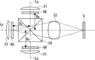
如图1所示,本实施方式的投影仪1主要具备光源2、集成光学系统3、色光分离光学系统4、光路长度校正用中继(relay)光学系统5、3个用于调制各色光的液晶光阀6R、6G、6B(光调制元件)、色光合成光学系统7、光传输光学系统8、偏振切换元件9、投影光学系统10。另外,在本实施方式的构成中,由于存在2个光传输光学系统,所以将以校正照明光路的光路长度为目的而使用的一方称作“光路长度校正用中继光学系统5”、将以向偏振切换元件传输液晶光阀所生成的图像光为目的而使用的一方称作“光传输光学系统8”(相当于权利要求书的“光传输光学系统”),由此来进行区别。As shown in FIG. 1 , a projector 1 according to this embodiment mainly includes a light source 2, an integrated
下面对投影仪1的各构成要素进行说明。Each component of the projector 1 will be described below.
光源2由超高压水银灯、氙气灯等构成,具有射出白色光的光源灯12、和反射来自光源灯12的光而使其朝向集成光学系统3射出的反射器13。集成光学系统3具有由复眼透镜等构成的第1透镜阵列14以及第2透镜阵列15、和叠加透镜16。集成光学系统3具有如下功能,即将从光源2射出的光的照度分布在各液晶光阀6R、6G、6B上大致均匀化的功能。The light source 2 is composed of an ultra-high pressure mercury lamp, a xenon lamp, etc., and has a
色光分离光学系统4具有二向色镜18、19和反射镜20。二向色镜18、19例如通过在玻璃表面层积电介质多层膜而形成,具有选择性地将入射的白色光中包含的规定波段的色光反射,而使除此之外的波段的色光透过的特性。二向色镜18使绿色光LG和蓝色光LB反射,而使红色光LR透过。二向色镜19使由二向色镜18反射后的色光中的绿色光LG反射,而使蓝色光LB透过。反射镜20使透过二向色镜18后的红色光LR朝向红色光调制用液晶光阀6R的平行化透镜21反射。The color separation optical system 4 has dichroic mirrors 18 , 19 and a reflection mirror 20 . The dichroic mirrors 18 and 19 are formed, for example, by laminating a dielectric multilayer film on the surface of glass, and selectively reflect the colored light of a predetermined wavelength band included in the incident white light, and transmit the colored light of other wavelength bands. past characteristics. The dichroic mirror 18 reflects the green light LG and the blue light LB, and transmits the red light LR. The dichroic mirror 19 reflects the green light LG among the colored lights reflected by the dichroic mirror 18 , and transmits the blue light LB. The reflection mirror 20 reflects the red light LR transmitted through the dichroic mirror 18 toward the parallelizing
光路长度校正用中继光学系统5具有入射侧透镜23、中继透镜24、和反射镜25、26,具有对因蓝色光LB与其他色光LR、LG相比到液晶光阀6B的光路长度更长而导致的光损失进行校正的功能。入射侧透镜23具有使光有效地入射到中继透镜24的功能。中继透镜24具有将入射侧透镜23附近的光传输到蓝色光调制用液晶光阀6B的前级的平行化透镜21附近的功能。通过光路长度校正用中继光学系统5,入射到入射侧透镜23的蓝色光LB,在光强度分布基本被保存的状态下几乎没有光损失地被传输到在空间上离开的液晶光阀6B。The optical path length correction relay optical system 5 has an incident side lens 23, a relay lens 24, and reflection mirrors 25, 26, and has a longer optical path length to the liquid crystal
各液晶光阀6R、6G、6B具备一对基板和夹持于基板间的液晶,具有能独立地控制透过率的多个像素排列成矩阵状的构成。在光透过区域,多条扫描线和多条数据线相互交叉地被设置,通过向多条数据线供给图像数据,另外按线顺序从一边向另一边扫描多条扫描线,从而向与各扫描线对应的行方向上排列的多个像素(像素群)写入图像数据。例如,红色光调制用的液晶光阀6R,根据图像数据对通过平行化透镜21大致平行地入射的红色光进行光调制,射出内部含有光学像的图像光。绿色光调制用的液晶光阀6G、蓝色光调制用的液晶光阀6B的作用也与红色光调制用的液晶光阀6R相同。Each of the liquid
另外,在本实施方式的情况下,图像数据由与左眼用图像对应的第1图像数据和与右眼用图像对应的第2图像数据构成。第1图像数据以线顺序方式被写入第1子帧(第1期间),第2图像数据以线顺序方式被写入与第1子帧在时间上相邻的第2子帧(第2期间)。反复进行这样的动作,从而交替地写入第1图像数据和第2图像数据。各液晶光阀6R、6G、6B根据被写入的第1图像数据或者第2图像数据来进行光调制。各子帧的帧频被设定为120Hz。In addition, in the case of the present embodiment, the image data is composed of first image data corresponding to the image for the left eye and second image data corresponding to the image for the right eye. The first image data is written in the first subframe (the first period) in a line-sequential manner, and the second image data is written in the second subframe (the second period) adjacent to the first subframe in time in a line-sequential manner. period). By repeating such operations, the first image data and the second image data are alternately written. Each of the liquid
色光合成光学系统7具有正交二向色棱镜28和波长选择相位板29。正交二向色棱镜28为4个三角柱棱镜彼此贴合而成的构造。三角柱棱镜中被贴合的面成为正交二向色棱镜28的选择反射面。在正交二向色棱镜28的内面,彼此垂直地形成有红色光LR反射而绿色光LG透过的选择反射面、和蓝色光LB反射而绿色光LG透过的选择反射面。入射到正交二向色棱镜28的绿色光LG通过选择反射面被直接射出,红色光LR和蓝色光LB在选择反射面上被选择性地反射,从而向着与绿色光LG的射出方向相同的方向射出。The color light combining optical system 7 has a cross
波长选择相位板29选择性地变换入射光当中的特定波段的色光的偏振状态,例如能够采用颜色选择器(Color Select)(Color Link公司的商品名)等。即、从各液晶光阀6R、6G、6B射出的图像光为透过射出侧偏振片(未图示)之后的直线偏振光,考虑到利用作为色光合成光学系统7的正交二向色棱镜28的效率,绿色光LG以P偏振光、红色光LR和蓝色光LB以S偏振光的状态入射到正交二向色棱镜28,并被合成为用于形成彩色图像的图像光射出。从正交二向色棱镜28射出的图像光入射到波长选择相位板29,仅绿色光LG的偏振方向旋转90度成为S偏振光,从而成为由偏振状态一致的3种色光构成的图像光并从波长选择相位板29射出。当然,也能够采用从各液晶光阀6R、6G、6B透过射出侧偏振片(未图示)后射出的各色光LR、LG、LB成为状态全部相同的直线偏振光(例如S偏振光)的构成,在该情况下不需要波长选择相位板29。The wavelength
光传输光学系统8具有入射侧透镜31、中继透镜32和射出侧透镜33。光传输光学系统8具有将从各液晶光阀6R、6G、6B射出的图像光传输到偏振切换元件9,并在偏振切换元件9中成像从而形成中间像的功能。本实施方式的光传输光学系统8采用了等倍传输光学系统,但也可以采用缩小传输光学系统或放大传输光学系统。关于光传输光学系统8的成像倍率将在后面进行说明。The light transmission
入射侧透镜31配置在各液晶光阀6R、6G、6B与正交二向色棱镜28之间。入射侧透镜31具有使来自各液晶光阀6R、6G、6B的图像光有效地入射到中继透镜32的功能。中继透镜32具有对入射侧透镜31附近的图像光进行传输以使其经由正交二向色棱镜28合成为一个并在偏振切换元件9上成像从而形成中间像的功能。另外,正交二向色棱镜28的色光合成特性具有入射角依存性,因而也可以不在各液晶光阀6R、6G、6B的射出侧配置入射侧透镜31,而是接近于正交二向色棱镜28的射出端面配置一个入射侧透镜,能够降低在色光合成时容易发生的彩色相位不均。射出侧透镜33具有使从中继透镜32射出的图像光有效地入射到偏振切换元件9的功能。The incident-
对于光传输光学系统8,优选例如畸变、横向色差等光学像差较少发生的光学系统,对于中继透镜32也同样。根据该观点,采用由多个透镜构成中继透镜32、使用非球面透镜、使用低色散性的玻璃材料等方法是有效的。另外,不局限于透镜,也可以采用反射镜等,或者组合透镜和反射镜而构成。另外,入射侧透镜31在提高传输效率方面是有效的,但并不是必须的光学要素,根据从液晶光阀6R、6G、6B射出的图像光的特性和光传输光学系统的构成的不同,也可以不设置入射侧透镜31。The light transmission
对于光传输光学系统8,说明了优选为较少发生光学像差的光学系统,但更详细地说,是优选图像传输特性的波长依存性较小的光学系统。这是因为,在各液晶光阀6R、6G、6B中,通过波段不同的光形成红色光用图像、绿色光用图像、蓝色光用图像,这些图像都是在一个光传输光学系统8中进行处理的。为此,优选采用零色散或低色散性的光学材料来构成。As for the light transmission
或者,作为其他方法,如图5所示那样,在各液晶光阀6R、6G、6B的射出侧配置光路长度校正光学系统35来对每个光路校正光路长度,以及如图6所示那样,改变各液晶光阀6R、6G、6B与偏振切换元件9之间的距离DR、DG、DB来对每个光路校正光路长度等方法是有效的。另外,在图6中,为了容易观察图面,表示距离DR、DG、DB的箭头仅描画了从各液晶光阀6R、6G、6B开始到射出光轴为止。Alternatively, as another method, as shown in FIG. 5 , an optical path length correction
并且,在具备多个液晶光阀的构成中,为了使各液晶光阀6R、6G、6B的图像光准确地叠加并可靠地传输到偏振切换元件9,需要在考虑上述光传输光学系统8的光学特性的同时将各液晶光阀6R、6G、6B与偏振切换元件9之间的光学距离设定成规定的关系。即、需要准确地设定各液晶光阀6R、6G、6B在投影光轴方向上的位置。然而,该设定并不是容易的事情。因此,至少在液晶光阀6R、6G、6B这一侧、优选在液晶光阀6R、6G、6B侧和偏振切换元件9侧这两侧采用具有远心性的光传输光学系统。所谓具有远心性的光学系统,是指主光线通过像侧焦点或者物体侧焦点的光学系统。通过采用这样的光学系统,即使液晶光阀6R、6G、6B或偏振切换元件9在光轴方向产生位置偏移,由于所传输的图像的尺寸和形状没有变化,所以也容易进行两元件的对位,能够实现准确的图像传输。In addition, in the configuration including a plurality of liquid crystal light valves, in order to accurately superimpose the image lights of the respective liquid
图4的(A)~(E)示出了这样的具有远心性的光传输光学系统的几个例子。图4的(A)是透镜方式的两侧远心的光传输光学系统的例子,具备2个透镜37A、37B和1个光圈38。图4的(B)是反射镜方式的两侧远心的光传输光学系统的例子,具备3个反射镜39A、39B、39C。图4的(C)是透镜和反射镜并用方式的两侧远心的光传输光学系统的例子,具备2个反射镜对40A、40B以及41A、41B、和1个透镜42。图4的(D)是两侧远心的缩小传输光学系统的例子,具备2个透镜43A、43B和1个光圈44。图4的(E)是物体侧远心的光传输光学系统的例子,具备1个透镜45和1个光圈46。(A) to (E) of FIG. 4 show some examples of such telecentric light transmission optical systems. (A) of FIG. 4 is an example of a lens type telecentric light transmission optical system, and includes two lenses 37A and 37B and one aperture 38 . (B) of FIG. 4 is an example of a double-side telecentric light transmission optical system of a mirror system, and includes three mirrors 39A, 39B, and 39C. (C) of FIG. 4 is an example of a bilaterally telecentric light transmission optical system using a combination of lenses and mirrors, and includes two mirror pairs 40A, 40B and 41A, 41B, and one lens 42 . (D) of FIG. 4 is an example of a telecentric reduction transmission optical system, and includes two lenses 43A and 43B and one
另外,和光传输光学系统8同样,作为色光合成光学系统7的正交二向色棱镜28也优选为较少发生光学像差的元件,优选采用零色散或低色散性的光学材料构成。In addition, like the light transmission
偏振切换元件9具有将从液晶光阀6R、6G、6B入射的光的偏振状态按时间切换成第1偏振状态和第2偏振状态的多个线状的切换区域,在多个切换区域中按线顺序来切换第1偏振状态和第2偏振状态。如图2的(A)、(B)所示那样,偏振切换元件9由如下液晶元件构成,该液晶元件在一对分别具有透明电极43、44的透明基板45、46之间以规定的取向状态封入有液晶47。作为能适用于偏振切换元件9的液晶元件的种类,能够采用例如强电介质液晶元件、P-液晶盒(Pi-cell)液晶元件、TN液晶元件等众所周知的液晶元件。对于偏振切换元件9,优选采用反应速度尽可能快的液晶元件。The
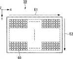
在一边的透明基板45上,形成有由透明导电膜构成的细长形状的多个线电极43。各线电极43的形成区域与将入射光的偏振状态按时间切换成第1偏振状态和第2偏振状态的各个切换区域对应。各线电极43(切换区域)的长度方向的尺寸和形状与在液晶光阀6R、6G、6B的行方向(扫描线的延伸方向)上排列的多个像素的全部相对应。另外,线电极43(切换区域)的数量与在液晶光阀6R、6G、6B的列方向(数据线的延伸方向)上排列的像素个数(行数)一致。在另一边的透明基板46上,在整面形成有由透明导电膜构成的对置电极44。A plurality of
线电极43的行方向的尺寸被设定为比在液晶光阀6R、6G、6B的行方向上排列的全部像素的两端部之间的尺寸稍大。因此,传输来自液晶光阀6R、6G、6B的图像光的区域G位于比线电极43的长度方向的两端部更靠近内侧的位置上。优选偏振切换元件9由能在x轴方向、y轴方向、z轴方向的所有方向进行位置调整的托架(保持部件)保持。虽然需要光传输光学系统8将液晶光阀6R、6G、6B的图像准确地传输到偏振切换元件9的规定位置,以使得在形成于液晶光阀6R、6G、6B上的图像的行方向上排列的像素群和偏振切换元件9的线电极43一一对应,但是通过设置上述的位置调整机构(保持部件),光传输光学系统8和偏振切换元件9的调整(对位)变得容易。The size of the
如图1所示那样,偏振切换元件9具备包括驱动元件和驱动电路(均未图示)的控制部49。控制部49与在液晶光阀6R、6G、6B向垂直方向进行的线顺序扫描同步地,对偏振切换元件9的线电极43和对置电极44之间依次施加电压,从而来控制夹入在线电极43和对置电极44之间的各个切换区域中的液晶的取向状态。由此,能够将入射到与特定的线电极相对应的切换区域后的偏振光的偏振状态按线顺序从第1偏振状态切换成第2偏振状态、或者从第2偏振状态切换成第1偏振状态,一边在例如图2的(A)的箭头E的方向上进行扫描一边射出。As shown in FIG. 1 , the
具体来讲,例如当使直线偏振光、即S偏振光入射到偏振切换元件9时,能够使偏振方向旋转90度从而作为P偏振光射出,或者不使偏振方向旋转而是保持S偏振光不变射出。由此,在使用彼此垂直的直线偏振光的情况下,可以使用构成简单的光闸眼镜,从而能够降低系统的成本。或者,在偏振切换元件9中组合1/4波阻片,能够作为左旋的圆偏振光射出,或者作为右旋的圆偏振光射出。由此,在使用彼此反向旋转的圆偏振光的情况下,即使从不正对投影图像的斜向观察投影图像也很少产生双重影像等,从而能够实现良好的立体视觉状态。Specifically, for example, when linearly polarized light, ie, S-polarized light, enters the
在多数的液晶光阀中,采用线顺序方式的图像数据写入方式。即、对在行方向上排列的所有像素群同时写入图像数据,并且该像素群在列方向上依次移动,由此对所有像素写入图像数据,最终完成1子帧的左眼用图像或右眼用图像。因此,与液晶光阀6R、6G、6B的线顺序写入方式相对应,以使得1条线电极43对应在行方向上排列的所有像素群的方式来构成偏振切换元件9。In most liquid crystal light valves, the image data writing method of the line sequential method is adopted. That is, image data is written simultaneously to all pixel groups arranged in the row direction, and the pixel groups are sequentially moved in the column direction, thereby writing image data to all pixels, and finally a left-eye image or a right-eye image of one subframe is completed. Eye image. Therefore, corresponding to the line-sequential writing method of the liquid
下面参照图3的(A)~(C),对从液晶光阀6R、6G、6B入射到偏振切换元件9的图像光通过偏振切换元件9变换成具有规定偏振状态的图像光并射出的状态进行说明。另外,图3的(A)表示入射到偏振切换元件9的图像光的状态,图3的(B)表示偏振切换元件9的状态,图3的(C)表示从偏振切换元件9射出的图像光的状态。Next, referring to (A) to (C) of FIG. 3 , the image light incident on the
仔细观察入射到偏振切换元件9的图像光可知,与在液晶光阀6R、6G、6B向垂直方向通过线顺序扫描进行的图像数据的写入相对应,该图像以线单位被连续重写。即、如图3的(A)所示那样,由入射到偏振切换元件9的图像光所形成的中间像在某一时间点上,前一子帧的图像与被重新重写的当前子帧的图像夹着规定的扫描线(规定的边界位置X)而并存。Careful observation of the image light incident on the
这里,控制部49与该扫描线(边界位置X)向垂直方向的移动同步地,如图3的(B)所示那样对偏振切换元件9的多个线电极43按线顺序施加规定的电压,以使得液晶的偏振状态为第1偏振状态的切换区域和液晶的偏振状态为第2偏振状态的切换区域之间的边界位置X1移动的方式,将液晶的取向状态依次切换成规定的状态。由此,透过偏振切换元件9的图像光如图3的(C)所示那样,能够在该边界位置X1的上下获得不同的偏振状态,而不会横跨扫描线而持续相同的偏振状态。例如,如果将具有第1偏振状态的前一子帧的图像视为左眼用图像、将具有第2偏振状态的当前子帧的图像视为右眼用图像,则能够在准确地区分偏振状态不同的左眼用和右眼用的种类的图像的同时,按时间交替地连续显示该左眼用和右眼用的种类的图像。Here, the
由此,按每个子帧将偏振状态完全不同的图像投影显示到屏幕51上。例如,假设第奇数个子帧图像为取得第1偏振状态的左眼用图像,第偶数个子帧图像为取得第2偏振状态的右眼用图像。观看者通过利用具备仅使用于左眼的第1偏振状态的光透过的偏振元件、和仅使用于右眼的第2偏振状态的光透过的偏振元件的偏振眼镜来观看具有上述偏振状态的投影图像,能够分别将第奇数个子帧图像仅分离引导到左眼,将第偶数个子帧图像仅分离引导到右眼,从而能够获得良好的立体视觉状态。As a result, images with completely different polarization states are projected and displayed on the screen 51 for each subframe. For example, it is assumed that the odd-numbered sub-frame images are left-eye images in the first polarization state, and the even-numbered sub-frame images are right-eye images in the second polarization state. The viewer watches through polarizing glasses having the above-mentioned polarization state by using a polarization element that transmits only the light of the first polarization state for the left eye and a polarization element that transmits only the light of the second polarization state for the right eye. The projection images of the odd-numbered sub-frame images can be separated and guided only to the left eye, and the even-numbered sub-frame images can be separated and guided only to the right eye, so that a good stereoscopic viewing state can be obtained.
这样,根据本实施方式的投影仪1,由于具备使来自各液晶光阀6R、6G、6B的图像光在偏振切换元件9上成像从而形成中间像的光传输光学系统8,所以即使液晶光阀6R、6G、6B和偏振切换元件9位于彼此离开的位置、并且来自液晶光阀6R、6G、6B的图像光为发散光,也能够使从液晶光阀6R、6G、6B的规定像素射出的图像光精确地入射到偏振切换元件9的规定的切换区域。另外,在偏振切换元件9中,由于液晶的偏振状态为第1偏振状态的切换区域和液晶的偏振状态为第2偏振状态的切换区域之间的边界位置,与液晶光阀6R、6G、6B的各图像的边界位置向垂直方向的移动同步地移动,所以无论是在空间上还是在时间上都能使液晶光阀6R、6G、6B中的各图像数据的写入、和偏振切换元件9中的偏振状态的切换同步。由此,投影图像的偏振状态不会产生局部错乱,从而能够实现高画质的立体图像显示。Thus, according to the projector 1 of this embodiment, since the image light from each liquid
另外,在本实施方式的投影仪1中,通过对2种偏振状态的图像光分别仅使用对应的一只眼睛进行观看来获得立体状态,因此在图像帧(子帧)的显示速度较慢的情况下,有时会感到因画质劣化而导致的画面闪烁。因此,优选图像帧(子帧)的显示速度在120Hz左右以上。In addition, in the projector 1 of the present embodiment, the stereoscopic state is obtained by viewing the image light in the two polarization states with only the corresponding one eye. Therefore, the display speed of the image frame (subframe) is slow. In some cases, the screen may flicker due to image quality degradation. Therefore, it is preferable that the display speed of the image frame (subframe) is about 120 Hz or higher.
在本实施方式中,由于使用了等倍传输光学系统来作为光传输光学系统8,因此通过采用具有与液晶光阀6R、6G、6B的像素区域相同的尺寸和形状的偏振切换区域的偏振切换元件9,能够实现准确的图像传输。然而,对于光传输光学系统的构成,也可以采用缩小传输光学系统或放大传输光学系统来代替等倍传输光学系统。在缩小传输光学系统、即对液晶光阀6R、6G、6B中形成的图像进行缩小并传输到偏振切换元件的构成中,能够使偏振切换元件和投影光学系统小型化,因此容易实现投影仪整体的小型化和低成本化。相应地,在放大传输光学系统、即对液晶光阀6R、6G、6B中形成的图像进行放大并传输到偏振切换元件的构成中,传输到偏振切换元件的中间像和偏振切换元件之间的对位变得容易,从而容易确保偏振切换元件的配置精度。In this embodiment, since the equal magnification transmission optical system is used as the light transmission
在本实施方式的情况下,偏振切换元件9被配置在投影光学系统10的焦点位置,由于偏振切换元件9与投影光学系统10之间不存在空气以外的夹杂物,所以能够使用后焦距长极短的投影光学系统。后焦距长越短,则F值越小,即使是大口径也能更容易地实现高性能的投影光学系统。因此,即使在将光传输光学系统中的图像传输的倍率设定为等倍以外的情况下,也能比较容易地实现与该构成相对应的投影光学系统。In the case of this embodiment, the
对于偏振切换元件9的线电极43(切换区域)的数量,虽然如本实施方式那样优选为与在液晶光阀6R、6G、6B的列方向上排列的像素数相同,但是并不局限于此。在偏振切换元件9的线电极43(切换区域)的数量与在液晶光阀6R、6G、6B的列方向上排列的像素数不一致的情况下,由于液晶光阀6R、6G、6B的行方向的像素群与偏振切换元件9的切换区域不一一对应,所以无法使液晶光阀6R、6G、6B中的各图像数据的边界位置与偏振切换元件9中的不同偏振状态的边界位置完全同步。因此,多少会产生投影图像的局部的偏振状态错乱、例如在边界位置附近本来应该是第1偏振状态的光束被作为第2偏振状态射出等。但是,如果偏振状态错乱的发生区域的大小与图像整体的大小相比极其微小,则基本不会影响实际应用。The number of line electrodes 43 (switching regions) of the
因此,也可以构成为偏振切换元件9的线电极43(切换区域)的数量小于在液晶光阀6R、6G、6B的列方向上排列的像素数。如果相对于液晶光阀6R、6G、6B的列方向的像素数形成有其1/3左右以上个数的线电极43,则偏振切换元件9能够基本获得所期望的效果。在构成为偏振切换元件9的线电极43(切换区域)的数量小于在液晶光阀6R、6G、6B的列方向上排列的像素数的情况下,能够简化偏振切换元件9的驱动元件和驱动电路,从而实现低成本化。Therefore, the number of wire electrodes 43 (switching regions) of the
相反,也可以构成为偏振切换元件9的线电极43(切换区域)的数量大于在液晶光阀6R、6G、6B的列方向上排列的像素数。在采用该构成的情况下,偏振切换元件9中的多个线电极43(切换区域)对应于液晶光阀6R、6G、6B中的行方向的1行像素群。例如,根据构成光调制元件的液晶元件的不同,有时依存于元件的结构和液晶的物性等需要较长的时间来进行图像数据的重写、即所谓的反应时间较长。在这种情况下,例如通过在图像数据重写的过渡期间内对应偏振切换元件9的多个切换区域来进行细微切换,能够精确地抑制投影光的偏振状态的局部错乱。Conversely, the number of wire electrodes 43 (switching regions) of the
另外,为了在偏振切换元件9中准确地切换图像光的偏振状态,优选入射到偏振切换元件9的图像光是偏振度较高的直线偏振光。虽然从作为光调制元件的液晶光阀6R、6G、6B射出的图像光是偏振度较高的直线偏振光,但是由于到达偏振切换元件9的途中存在的色光合成光学系统7(例如、具有由电介质多层膜形成的二向色膜的正交二向色棱镜)和光传输光学系统8(具备具有曲率的透镜类),偏振会被打乱,偏振度会降低。In addition, in order to accurately switch the polarization state of the image light in the
因此,如图7所示那样,优选在光传输光学系统8的中继透镜32与偏振切换元件9之间的光路上配置偏振补偿光学系统53,该偏振补偿光学系统53用于补偿因色光合成光学系统7和光传输光学系统8而产生的偏振错乱。根据该构成,由于入射到偏振切换元件9的偏振光的偏振度得到提高,所以能够通过偏振切换元件9准确地切换投影光的偏振状态,从而能够实现高画质的立体图像显示。Therefore, as shown in FIG. 7, it is preferable to arrange a polarization compensation
作为偏振补偿光学系统53,能够使用众所周知的纠正仪。纠正仪由1/2波阻片71和没有折射能力的透镜72构成。没有折射能力的透镜72由一对具有强折射面的凸透镜73和凹透镜74的组合构成。没有折射能力的透镜72使透过光线的P偏振光成分和S偏振光成分产生透过率差,能够使偏振平面旋转。通过调整其曲面的曲率半径、玻璃折射率,能够大范围地调节偏振光的旋转程度。而且,通过在1/2波阻片71的表面和没有折射能力的透镜72的各面形成用于产生所期望的延迟的电介质多层膜,能够对透过光线施加所期望的延迟。As the polarization compensation
通过使从液晶光阀6R、6G、6B射出的各色的偏振光透过正交二向色棱镜28和中继透镜32而产生的偏振变化并不是完全相同。在正交二向色棱镜28中,绿色光(G光)透过R光反射面和B光反射面。红色光(R光)在R光反射面被反射,在B光反射面透过。蓝色光(B光)在R光反射面透过,在B光反射面被反射。因此,各色光在R光反射面和B光反射面的电介质多层膜(R光反射二向色膜、B光反射二向色膜)所接受的延迟不同。另外,在中继透镜32中,根据玻璃折射率的色散的不同,偏振平面的旋转程度对于每个色光也不同。The polarization changes produced by passing the polarized light of each color emitted from the liquid
根据以上理由,难以利用纠正仪在整个波段完全地使偏振变化复原,为了实现该目的可能会导致偏振补偿光学系统大型化、复杂化和成本大幅上升。在这种情况下,例如以使得人类的视见度最高的G光的偏振状态最小的方式来构成纠正仪。具体来讲,调整纠正仪的电介质多层膜和无折射能力的透镜72的曲率半径、玻璃材料,以使得G光所接受的延迟和偏振平面的旋转最小。由此,能够避免偏振补偿光学系统53(纠正仪)的大型化、复杂化和成本上升,同时能够最有效地补偿图像光的偏振状态从而显示高画质的立体图像。另外,在使用超高压水银灯等水银灯作为光源2的情况下,优选在G光波段强度最高的e线(546.1nm)附近使延迟和偏振平面旋转最小。For the above reasons, it is difficult to completely restore the polarization change over the entire wavelength range by using a corrector, and the realization of this purpose may lead to an increase in the size, complexity, and cost of the polarization compensation optical system. In this case, for example, the corrective device is configured such that the polarization state of G light, which is the most visible to humans, is minimized. Specifically, the dielectric multilayer film of the rectifier and the radius of curvature of the non-refractive lens 72, glass material are adjusted to minimize the retardation and polarization plane rotation received by the G light. Thus, while avoiding the increase in size, complexity, and cost of the polarization compensation optical system 53 (corrector), it is possible to most effectively compensate the polarization state of image light and display a high-quality stereoscopic image. In addition, when a mercury lamp such as an ultra-high pressure mercury lamp is used as the light source 2, it is preferable to minimize retardation and polarization plane rotation near the e-line (546.1 nm) having the highest intensity in the G light band.
对于能配置偏振补偿光学系统53的场所,由于空间的制约等而被限定在来自各液晶光阀6R、6G、6B的色光被正交二向色棱镜28合成之后(偏振切换元件9侧)、且靠近偏振切换元件9的位置。另外,在红色光、绿色光、蓝色光的各光路中,由于夹在中间的二向色元件等的光学特性不同,所使用的光学材料具有波长色散性等理由,各光路中的偏振度下降的程度不一样。因此,无法在全波段补偿入射到偏振切换元件9的图像光的偏振度。因此,在本构成中,优选采用配合偏振度的下降最大的色光来设定偏振补偿量的方法。或者,优选采用以使得偏振度的下降在3色的色光之间被平均化的方式来设定偏振补偿量的方法。The place where the polarization compensating
另外,在本例中,在构成纠正仪的光学元件的至少1面以上形成用于对在正交二向色棱镜28和中继透镜32中产生的延迟进行补偿的电介质多层膜,但是电介质多层膜的形成位置不局限于纠正仪,只要能实现同等功能,则也可以形成于其他光学元件的面上。具体来讲,可以列举正交二向色棱镜28的光射出面和中继透镜32的各透镜面。而且,虽然通常在这些面上形成有反射防止膜,但是也能够通过在这些面的至少一面上不形成反射防止膜来有效地产生补偿用的延迟。In addition, in this example, a dielectric multilayer film for compensating the retardation generated in the cross
另外,纠正仪的配置位置不局限于中继透镜32的后级(光射出侧),也可以在中继透镜32的前级(光入射侧)。在这种情况下,例如可以将图7所示的纠正仪中的无折射率的透镜72配置于前级,将1/2波阻片71配置于后级。In addition, the disposition position of the corrector is not limited to the rear stage (light emission side) of the
如上所述,通过使用偏振补偿光学系统53,能够几乎不导致光损失地补偿偏振的错乱。相应地,也可以采用不使用偏振补偿光学系统53而是将光吸收型或光反射型的偏振元件配置在偏振切换元件的入射侧的构成。作为偏振元件,能够利用使用了高分子原材料的拉伸膜的光吸收型偏振元件、使光吸收性的微粒子取向了的光吸收型偏振元件、和利用了结构双折射性的光反射型或光吸收型偏振元件等。根据该构成,能够以低成本补偿偏振的错乱。As described above, by using the polarization compensating
这里,优选将这些偏振元件配置在偏振切换元件的正前方(液晶光阀侧)。由于这些偏振元件均为对不需要的偏振成分的光进行吸收或反射来将其排除的元件,所以入射到偏振切换元件的直线偏振光的偏振度得到提高,能够利用偏振切换元件准确地切换图像光的偏振状态,从而能够实现高画质的立体视觉状态。Here, these polarizing elements are preferably arranged directly in front of the polarization switching element (on the side of the liquid crystal light valve). Since these polarizing elements are elements that absorb or reflect light of unnecessary polarization components to exclude them, the degree of polarization of linearly polarized light incident on the polarization switching element is increased, and images can be accurately switched using the polarization switching element The polarization state of light can realize high-quality stereoscopic vision.
另外,也可以将偏振元件紧贴偏振切换元件的入射端面而配置。而且,如果使用光吸收型偏振元件,则在设置空间受限时比较有效。不过,也可以构成为,使用反射型偏振元件,使不需要的偏振成分的光透过从而被排除,并使作为反射光的图像光入射到偏振切换元件。In addition, the polarizing element may be arranged in close contact with the incident end face of the polarization switching element. Furthermore, using a light-absorbing polarizing element is effective when the installation space is limited. However, a reflective polarizing element may be used to transmit and exclude light of unnecessary polarization components, and to allow image light as reflected light to enter the polarization switching element.
[第2实施方式][the second embodiment]
下面参照图8对本发明的第2实施方式进行说明。Next, a second embodiment of the present invention will be described with reference to FIG. 8 .
本实施方式的投影仪的基本构成与第1实施方式相同,由于只是液晶光阀的图像数据的写入形式与第1实施方式不同,所以仅对该点进行说明。The basic configuration of the projector of this embodiment is the same as that of the first embodiment, and only the writing format of the image data of the liquid crystal light valve is different from the first embodiment, so only this point will be described.
图8是表示本实施方式的投影仪的偏振切换元件的图,是从图1中的z轴方向观察的xy俯视图。FIG. 8 is a diagram showing a polarization switching element of the projector according to the present embodiment, and is an xy plan view viewed from the z-axis direction in FIG. 1 .
在第1实施方式的情况下,对液晶光阀6R、6G、6B的图像数据的写入方式为线顺序方式的情况进行了说明。但是,在液晶光阀中,有时也采用点顺序方式作为图像数据的写入方式。本实施方式的投影仪使用采用了点顺序方式的图像数据写入方式的液晶光阀来作为光调制元件。在点顺序方式的液晶光阀中,一个一个地依次选择配置成矩阵状的像素来写入图像数据,最终完成1帧的图像。In the case of the first embodiment, the case where the image data writing method of the liquid
在使用这种写入方式的液晶光阀的情况下,与第1实施方式的线电极43不同,如图8所示那样,需要使用以使得和液晶光阀的像素排列大致对应的方式将多个像素状电极60设置成矩阵状的偏振切换元件59。在本实施方式中,在偏振切换元件59上形成的中间像在某一时间点上,前一子帧的图像和被重新重写的当前子帧的图像夹着规定的边界位置而并存。In the case of using a liquid crystal light valve of such a writing method, unlike the
但是,在本实施方式的情况下,该边界位置并不仅仅向垂直方向移动,而是以如下方式沿水平方向和垂直方向的两个方向移动,即:在相对于规定行的像素群,在水平方向上朝着箭头E1所示的方向移动之后,再在垂直方向上朝着箭头E2所示的方向移动,并相对于下一行的像素群再次在水平方向上移动。与此同时,控制部对偏振切换元件59的多个像素状电极60按点顺序施加规定的电压,以使得液晶为第1偏振状态的切换区域和液晶为第2偏振状态的切换区域之间的边界位置与数据写入的边界位置的移动同步地移动的方式,将液晶的取向状态依次切换成规定的状态。However, in the case of the present embodiment, the boundary position does not move only in the vertical direction, but moves in both the horizontal direction and the vertical direction in such a manner that, with respect to the pixel group of a predetermined row, at After moving in the direction indicated by the arrow E1 in the horizontal direction, it moves in the direction indicated by the arrow E2 in the vertical direction, and then moves in the horizontal direction again relative to the pixel group in the next row. At the same time, the control unit applies predetermined voltages to the plurality of pixel-
在本实施方式中,无论是在时间上还是在空间上都能使液晶光阀中的各图像数据的写入和偏振切换元件中的偏振状态的切换同步,因此能够得到与第1实施方式相同的效果,即投影图像的偏振状态不会局部错乱,从而能够实现高画质的立体图像显示。In the present embodiment, the writing of each image data in the liquid crystal light valve and the switching of the polarization state in the polarization switching element can be synchronized both temporally and spatially, and therefore the same as the first embodiment can be obtained. The effect, that is, the polarization state of the projected image will not be locally disturbed, so that high-quality stereoscopic image display can be realized.
[第3实施方式][the third embodiment]
下面参照图9对本发明的第3实施方式进行说明。Next, a third embodiment of the present invention will be described with reference to FIG. 9 .
在第1实施方式中,使用了透过型的液晶光阀作为光调制元件,但是在本实施方式的投影仪中,对使用了反射型的液晶光阀作为光调制元件的构成例进行说明。In the first embodiment, a transmissive liquid crystal light valve is used as the light modulation element, but in the projector of this embodiment, a configuration example using a reflective liquid crystal light valve as the light modulation element will be described.
图9是本实施方式的投影仪的简要构成图。在图9中,对与第1实施方式的图1共同的构成要素标记相同的符号,并省略其说明。FIG. 9 is a schematic configuration diagram of a projector according to this embodiment. In FIG. 9 , components common to those in FIG. 1 of the first embodiment are denoted by the same reference numerals, and description thereof will be omitted.
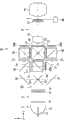
在本实施方式的投影仪61中,如图9所示那样,在构成集成光学系统3的叠加透镜16的射出侧设置有作为色光分离光学系统62的二向色镜63、64。二向色镜63使绿色光LG和蓝色光LB反射,使红色光LR透过。二向色镜64使绿色光LG和蓝色光LB透过,使红色光LR反射。另外,在被二向色镜63反射的绿色光LG和蓝色光LB的光路上,设有反射镜65、和二向色镜66。二向色镜66将被二向色镜63反射的绿色光LG和蓝色光LB中的绿色光LG反射,将蓝色光LB透过。In the
被二向色镜64反射的红色光LR在反射镜67上反射,经由平行化透镜21入射到偏振光分离棱镜68。偏振光分离棱镜68具备例如使P偏振光透过而使S偏振光反射的偏振光分离面,红色光LR通过偏振光分离面从而成为特定的偏振状态、例如P偏振光,并入射到反射型的液晶光阀69R。被液晶光阀69R调制成不同偏振状态的光、例如S偏振光,在偏振光分离棱镜68的偏振光分离面反射,并入射到作为色光合成光学系统的二向色棱镜28。被二向色镜66反射的绿色光LG、和透过二向色镜66的蓝色光LB的动作与红色光LR相同,这里省略说明。其他构成和作用与第1实施方式相同。The red light LR reflected by the
另外,在本构成例中,将光传输光学系统8的入射侧透镜31配置在偏振光分离棱镜68与正交二向色棱镜28之间,但是也可以配置在偏振光分离棱镜68与液晶光阀69R、69G、69B之间。并且,也可以将3个入射侧透镜31集成从而在正交二向色棱镜28的射出侧配置1个透镜。In addition, in this configuration example, the incident-
在本实施方式中,无论是在时间上还是在空间上均能使液晶光阀69R、69G、69B中的各图像数据的写入和偏振切换元件9中的偏振状态的切换同步,因此能够获得与第1实施方式相同的效果,即投影图像的偏振状态不会局部错乱,从而能够实现高画质的立体图像显示。In the present embodiment, the writing of the respective image data in the liquid
另外,本发明的技术范围不局限于上述实施方式,可以在不脱离本发明的主题的范围中施加各种变更。例如在上述实施方式中,采用了液晶元件作为偏振切换元件,但是如果是能够按时间局部地高速切换偏振状态的元件,则不局限于液晶元件。另外,作为光调制元件,除了透过型液晶光阀和反射型液晶光阀之外,也可以采用使用线顺序方式或点顺序方式的图像数据写入方式的其他光调制元件。此外,上述实施方式的投影仪的各部的具体构成不局限于上述实施方式,可以进行适当变更。In addition, the technical scope of this invention is not limited to the said embodiment, Various changes can be added in the range which does not deviate from the subject matter of this invention. For example, in the above-mentioned embodiments, a liquid crystal element is used as the polarization switching element, but it is not limited to a liquid crystal element as long as it is an element capable of locally switching the polarization state at high speed with time. In addition, as the light modulation element, besides the transmissive liquid crystal light valve and the reflective liquid crystal light valve, other light modulation elements using the image data writing method using the line sequential method or the dot sequential method may be used. In addition, the specific configuration of each part of the projector in the above-mentioned embodiment is not limited to the above-mentioned embodiment, and can be appropriately changed.
Claims (11)
Applications Claiming Priority (2)
| Application Number | Priority Date | Filing Date | Title |
|---|---|---|---|
| JP2010-085850 | 2010-04-02 | ||
| JP2010085850AJP5402791B2 (en) | 2010-04-02 | 2010-04-02 | projector |
Publications (2)
| Publication Number | Publication Date |
|---|---|
| CN102213899A CN102213899A (en) | 2011-10-12 |
| CN102213899Btrue CN102213899B (en) | 2013-12-25 |
Family
ID=44709298
Family Applications (1)
| Application Number | Title | Priority Date | Filing Date |
|---|---|---|---|
| CN2011100871422AExpired - Fee RelatedCN102213899B (en) | 2010-04-02 | 2011-04-02 | Projector |
Country Status (3)
| Country | Link |
|---|---|
| US (1) | US8529066B2 (en) |
| JP (1) | JP5402791B2 (en) |
| CN (1) | CN102213899B (en) |
Families Citing this family (17)
| Publication number | Priority date | Publication date | Assignee | Title |
|---|---|---|---|---|
| JP5360683B2 (en)* | 2009-04-01 | 2013-12-04 | セイコーエプソン株式会社 | projector |
| DE112011104705T5 (en)* | 2011-01-12 | 2013-10-31 | Arisawa Mfg. Co., Ltd. | Stereoscopic image display device |
| US20120299805A1 (en)* | 2011-05-26 | 2012-11-29 | Sanyo Electric., Ltd. | Projection display apparatus |
| US8567957B2 (en)* | 2011-07-11 | 2013-10-29 | Microvision, Inc. | Active polarization switch for speckle reduction in laser projection sources |
| US8870381B2 (en)* | 2011-08-10 | 2014-10-28 | Microvision, Inc. | Mixed polarization imaging system for three-dimensional projection and corresponding methods |
| KR101916719B1 (en)* | 2012-04-10 | 2019-01-30 | 엘지전자 주식회사 | Image projection apparatus |
| US10310289B2 (en) | 2012-10-04 | 2019-06-04 | North Inc. | Light assembly |
| KR102028987B1 (en) | 2013-03-29 | 2019-10-07 | 엘지디스플레이 주식회사 | Hologram image display device |
| JP6471424B2 (en)* | 2013-11-13 | 2019-02-20 | セイコーエプソン株式会社 | projector |
| CN106164751A (en)* | 2014-03-04 | 2016-11-23 | 斯特立体影像科技有限公司 | Modulator for stereoscopic image device and stereoscopic image device using the modulator |
| CA2941655C (en)* | 2014-03-05 | 2021-03-09 | Arizona Board Of Regents On Behalf Of The University Of Arizona | Wearable 3d augmented reality display with variable focus and/or object recognition |
| TWI553392B (en)* | 2015-01-06 | 2016-10-11 | 台達電子工業股份有限公司 | Polarized projection device and polarized projection system using the same |
| JP6582487B2 (en)* | 2015-03-27 | 2019-10-02 | セイコーエプソン株式会社 | Light source device, lighting device, and projector |
| US10153838B1 (en)* | 2016-12-28 | 2018-12-11 | Facebook, Inc. | Quad tracker with birefringent optics |
| CN114930243A (en)* | 2020-01-22 | 2022-08-19 | 索尼集团公司 | Optical system |
| JP7631978B2 (en)* | 2021-03-29 | 2025-02-19 | セイコーエプソン株式会社 | projector |
| CN113347406A (en)* | 2021-05-30 | 2021-09-03 | 深圳市慧创立科技有限公司 | Automatic switch over 3D equipment |
Citations (4)
| Publication number | Priority date | Publication date | Assignee | Title |
|---|---|---|---|---|
| US5982538A (en)* | 1994-01-28 | 1999-11-09 | Mitsubishi Denki Kabushiki Kaisha | Stereoscopic image projection apparatus and telecentric zoom lens |
| JP2003199125A (en)* | 2001-12-25 | 2003-07-11 | Nitto Kogaku Kk | Video projector and video projection method |
| CN101398536A (en)* | 2007-09-24 | 2009-04-01 | 鸿富锦精密工业(深圳)有限公司 | Stereo projection optical system |
| CN101625467A (en)* | 2008-07-09 | 2010-01-13 | 乐金显示有限公司 | Stereoscopic 3D liquid crystal display |
Family Cites Families (8)
| Publication number | Priority date | Publication date | Assignee | Title |
|---|---|---|---|---|
| JPS6318894A (en) | 1986-07-11 | 1988-01-26 | Kawasaki Heavy Ind Ltd | Reproduction method for stereoscopic image |
| JPH05232403A (en)* | 1992-02-20 | 1993-09-10 | Ricoh Co Ltd | Display device |
| JPH0954375A (en) | 1995-08-15 | 1997-02-25 | Nec Home Electron Ltd | Liquid crystal projection device for stereoscopic vision |
| JP2002101427A (en)* | 2000-09-22 | 2002-04-05 | Denso Corp | Stereoscopic image display device and method of controlling stereoscopic image display device |
| JP3895268B2 (en)* | 2002-12-06 | 2007-03-22 | 株式会社東芝 | Stereoscopic image display device |
| JP5635773B2 (en)* | 2006-09-29 | 2014-12-03 | リアルディー インコーポレイテッドRealD Inc. | Polarization conversion system for stereoscopic projection, projection system, and stereoscopic image projection method |
| JP2009151151A (en)* | 2007-12-21 | 2009-07-09 | Sony Corp | Stereoscopic video display apparatus |
| JP5360683B2 (en) | 2009-04-01 | 2013-12-04 | セイコーエプソン株式会社 | projector |
- 2010
- 2010-04-02JPJP2010085850Apatent/JP5402791B2/ennot_activeExpired - Fee Related
- 2011
- 2011-04-01USUS13/078,280patent/US8529066B2/ennot_activeExpired - Fee Related
- 2011-04-02CNCN2011100871422Apatent/CN102213899B/ennot_activeExpired - Fee Related
Patent Citations (4)
| Publication number | Priority date | Publication date | Assignee | Title |
|---|---|---|---|---|
| US5982538A (en)* | 1994-01-28 | 1999-11-09 | Mitsubishi Denki Kabushiki Kaisha | Stereoscopic image projection apparatus and telecentric zoom lens |
| JP2003199125A (en)* | 2001-12-25 | 2003-07-11 | Nitto Kogaku Kk | Video projector and video projection method |
| CN101398536A (en)* | 2007-09-24 | 2009-04-01 | 鸿富锦精密工业(深圳)有限公司 | Stereo projection optical system |
| CN101625467A (en)* | 2008-07-09 | 2010-01-13 | 乐金显示有限公司 | Stereoscopic 3D liquid crystal display |
Also Published As
| Publication number | Publication date |
|---|---|
| JP2011215529A (en) | 2011-10-27 |
| US20110242490A1 (en) | 2011-10-06 |
| US8529066B2 (en) | 2013-09-10 |
| JP5402791B2 (en) | 2014-01-29 |
| CN102213899A (en) | 2011-10-12 |
Similar Documents
| Publication | Publication Date | Title |
|---|---|---|
| CN102213899B (en) | Projector | |
| US8922722B2 (en) | Projection apparatus for providing multiple viewing angle images | |
| KR101614956B1 (en) | Head-mounted single-panel stereoscopic display | |
| US7675684B1 (en) | Compact optical system | |
| CA2921760C (en) | Polarization conversion system and method for stereoscopic projection | |
| US8696133B2 (en) | Projection optical system and image projecting device | |
| EP1647963A1 (en) | A colorful projection display device | |
| JP2012532341A (en) | Stereoscopic projection system using spatial multiplexing on the intermediate image plane | |
| JP6070127B2 (en) | Image display device and image display system | |
| US20230418068A1 (en) | Anamorphic directional illumination device | |
| JP2867529B2 (en) | Projection display device | |
| US7106389B2 (en) | Optical shifter and projection type optical display system | |
| US9075300B2 (en) | Projector | |
| JP3297191B2 (en) | Projection display device | |
| US8567956B2 (en) | Projector | |
| KR100580218B1 (en) | Projection type 3D image display device using one projector | |
| US6817718B2 (en) | Projection type optical display system | |
| JP6515589B2 (en) | Projector and transmission type display device | |
| JP2006058588A (en) | Optical device, optical apparatus, display apparatus, and stereoscopic image display apparatus | |
| JP2011257645A (en) | Projector | |
| US8888292B2 (en) | Projection apparatus for providing multiple viewing angle images | |
| JP2015145934A (en) | projector | |
| JP2015034996A (en) | Projector | |
| US20250164798A1 (en) | Anamorphic Near-Eye Display Device | |
| JPH11289559A (en) | Projection type stereoscopic image display device |
Legal Events
| Date | Code | Title | Description |
|---|---|---|---|
| C06 | Publication | ||
| PB01 | Publication | ||
| C10 | Entry into substantive examination | ||
| SE01 | Entry into force of request for substantive examination | ||
| C14 | Grant of patent or utility model | ||
| GR01 | Patent grant | ||
| CF01 | Termination of patent right due to non-payment of annual fee | ||
| CF01 | Termination of patent right due to non-payment of annual fee | Granted publication date:20131225 Termination date:20210402 |