CN102208315B - Compact relativity backward wave oscillator (RBWO) with adjustable low-frequency-range frequency - Google Patents
Compact relativity backward wave oscillator (RBWO) with adjustable low-frequency-range frequencyDownload PDFInfo
- Publication number
- CN102208315B CN102208315BCN2011101066661ACN201110106666ACN102208315BCN 102208315 BCN102208315 BCN 102208315BCN 2011101066661 ACN2011101066661 ACN 2011101066661ACN 201110106666 ACN201110106666 ACN 201110106666ACN 102208315 BCN102208315 BCN 102208315B
- Authority
- CN
- China
- Prior art keywords
- collector
- left end
- slow
- frequency
- radius
- Prior art date
- Legal status (The legal status is an assumption and is not a legal conclusion. Google has not performed a legal analysis and makes no representation as to the accuracy of the status listed.)
- Expired - Fee Related
Links
- 239000004020conductorSubstances0.000claimsabstractdescription51
- 230000005855radiationEffects0.000claimsabstractdescription26
- 238000007789sealingMethods0.000claimsabstractdescription15
- 238000010894electron beam technologyMethods0.000claimsdescription16
- 229910001220stainless steelInorganic materials0.000claimsdescription5
- 239000010935stainless steelSubstances0.000claimsdescription5
- XAGFODPZIPBFFR-UHFFFAOYSA-NaluminiumChemical compound[Al]XAGFODPZIPBFFR-UHFFFAOYSA-N0.000claimsdescription3
- 229910052782aluminiumInorganic materials0.000claimsdescription3
- 239000000463materialSubstances0.000claimsdescription3
- 241000826860TrapeziumSpecies0.000claims3
- 210000003298dental enamelAnatomy0.000claims1
- 230000001105regulatory effectEffects0.000claims1
- 239000000203mixtureSubstances0.000abstractdescription3
- 230000009286beneficial effectEffects0.000abstract1
- 238000004088simulationMethods0.000description9
- 238000010586diagramMethods0.000description6
- 239000002245particleSubstances0.000description6
- RYGMFSIKBFXOCR-UHFFFAOYSA-NCopperChemical compound[Cu]RYGMFSIKBFXOCR-UHFFFAOYSA-N0.000description5
- 230000000694effectsEffects0.000description5
- 238000005516engineering processMethods0.000description5
- 238000012545processingMethods0.000description5
- 230000004323axial lengthEffects0.000description4
- 238000004364calculation methodMethods0.000description4
- 238000000034methodMethods0.000description4
- 238000011160researchMethods0.000description4
- 238000011161developmentMethods0.000description3
- 230000018109developmental processEffects0.000description3
- 230000008569processEffects0.000description3
- 238000004804windingMethods0.000description3
- 238000010521absorption reactionMethods0.000description2
- 230000005540biological transmissionEffects0.000description2
- 230000008859changeEffects0.000description2
- 238000006243chemical reactionMethods0.000description2
- 230000008878couplingEffects0.000description2
- 238000010168coupling processMethods0.000description2
- 238000005859coupling reactionMethods0.000description2
- 230000007123defenseEffects0.000description2
- 238000013461designMethods0.000description2
- 238000002474experimental methodMethods0.000description2
- 238000000605extractionMethods0.000description2
- -1polytetrafluoroethylenePolymers0.000description2
- 229920001343polytetrafluoroethylenePolymers0.000description2
- 239000004810polytetrafluoroethyleneSubstances0.000description2
- 229910052802copperInorganic materials0.000description1
- 239000010949copperSubstances0.000description1
- 230000005684electric fieldEffects0.000description1
- 230000005520electrodynamicsEffects0.000description1
- 230000010355oscillationEffects0.000description1
- 239000000523sampleSubstances0.000description1
- 238000004904shorteningMethods0.000description1
- 230000009897systematic effectEffects0.000description1
Images


Landscapes
- Plasma Technology (AREA)
Abstract
Translated fromChineseDescription
Translated fromChinese技术领域technical field
本发明涉及高功率微波技术领域的微波源器件,尤其是一种紧凑型、低频段、频率可调相对论返波振荡器RBWO(Relativistic Backward-Wave Oscillator)。The invention relates to microwave source devices in the technical field of high-power microwaves, in particular to a compact, low-frequency, frequency-adjustable relativistic back-wave oscillator RBWO (Relativistic Backward-Wave Oscillator).
背景技术Background technique
近年来,高功率微波(根据Benford和Swegle的约定,高功率微波指峰值功率大于100MW、频率在1~300GHz之间的电磁波)在众多领域中的诱人前景引起了许多国家的广泛关注和大量研究投入,并已取得极大的技术进步。目前,已经提出的高功率微波应用多种多样:高功率微波定向能武器、卫星和空间平台供能、小型深空探测器的发射、轨道飞行器高度改变推进系统、电子高能射频加速器、材料加工与处理等。然而,无论哪一种应用都需要不同频段、较高功率的微波支持。作为高功率微波系统的核心器件,高功率微波源利用强流相对论电子束与器件内部腔体的谐振模式相互作用,进而辐射高功率微波。因此,研制频率可调、高功率、高效率以及紧凑型高功率微波源是高功率微波技术发展的重要方向之一。In recent years, the attractive prospect of high-power microwave (according to the agreement of Benford and Swegle, high-power microwave refers to the electromagnetic wave with a peak power greater than 100MW and a frequency between 1 and 300GHz) in many fields has attracted widespread attention in many countries and a large number of Research has been invested and great technological progress has been made. At present, a variety of applications of high-power microwaves have been proposed: high-power microwave directed energy weapons, energy supply for satellites and space platforms, launch of small deep-space probes, altitude-changing propulsion systems for orbiters, electronic high-energy radio-frequency accelerators, material processing and processing etc. However, no matter which application requires different frequency bands and higher power microwave support. As the core device of the high-power microwave system, the high-power microwave source utilizes the high-current relativistic electron beam to interact with the resonant mode of the internal cavity of the device, and then radiates high-power microwaves. Therefore, the development of frequency-tunable, high-power, high-efficiency and compact high-power microwave sources is one of the important directions for the development of high-power microwave technology.
RBWO是发展较成熟的振荡器型的高功率微波源,具有结构简单、效率高以及适合重复频率工作等优点,在工业和国防领域有着广泛的应用前景。由于RBWO的工作频段与器件的尺寸存在密切的关系,高频段器件尺寸较小,而低频段器件尺寸较大。此外,低频段器件还需要配备体积较大的螺线管磁场对电子束进行约束,造成整个系统庞大,不利于加工和实验。因此,RBWO在向低频段(<2GHz)拓展遇到了很大困难。然而,低频段高功率微波具有以下优点:微波波长长,绕射能力强,因而容易穿越遮蔽物,与目标体直接发生相互作用;微波的自由空间传输损耗小,传输距离远。因此,研究具有紧凑结构的低频段RBWO具有重要的理论和现实意义。另外,构造方便可调的电动力学结构以实现输出微波频率可调,具有重要的实际应用价值,是高功率微波的重要研究方向之一。RBWO is a well-developed oscillator-type high-power microwave source, which has the advantages of simple structure, high efficiency and suitable for repetition frequency work, etc., and has broad application prospects in the fields of industry and national defense. Due to the close relationship between the working frequency band of RBWO and the size of the device, the size of the high frequency band device is small, while the size of the low frequency band device is large. In addition, low-frequency devices also need to be equipped with a large solenoid magnetic field to confine the electron beam, resulting in a bulky system that is not conducive to processing and experiments. Therefore, RBWO has encountered great difficulties in expanding to the low frequency band (<2GHz). However, low-frequency high-power microwaves have the following advantages: microwaves have long wavelengths and strong diffraction capabilities, so they are easy to pass through shelters and interact directly with targets; microwaves have low transmission loss in free space and long transmission distances. Therefore, it is of great theoretical and practical significance to study low-band RBWOs with compact structures. In addition, constructing a convenient and adjustable electrodynamic structure to realize the adjustable output microwave frequency has important practical application value and is one of the important research directions of high-power microwave.
目前,对RBWO的研究多集中在S、C、X和毫米波段,对P、L波段等低频段在理论方面研究较少,实验方面更是没有报导。其中,研究L波段器件具有代表性的是采用同轴结构缩小器件的径向尺寸【牛洪昌,钱宝良.紧凑型L波段同轴相对论返波振荡器的粒子模拟.强激光与粒子束,2006,Vol.18,No.11,pp.1879-1882】。这种器件由阴极座、阴极、阳极外筒、截止颈、慢波结构、内导体、收集极、微波输出口、螺线管磁场、吸波介质、支撑杆组成,整个结构关于中心轴线旋转对称。虽然该论文公布了该结构的组成,但该结构只是初步建立的数值仿真模型,没有具体技术方案,从论文的描述中只能简要知道本结构的大致连接关系。为了叙述方便,下文中将沿轴线方向上靠近阴极座的一侧称为左端,远离阴极座的一侧称为右端。At present, the research on RBWO is mostly concentrated in the S, C, X and millimeter wave bands, and there are few theoretical studies on low frequency bands such as P and L bands, and there are no reports on experiments. Among them, the representative study of L-band devices is to use a coaxial structure to reduce the radial size of the device [Niu Hongchang, Qian Baoliang. Particle simulation of a compact L-band coaxial relativistic return wave oscillator. Strong Laser and Particle Beam, 2006 , Vol.18, No.11, pp.1879-1882]. This device is composed of cathode seat, cathode, anode outer cylinder, cut-off neck, slow wave structure, inner conductor, collector, microwave output port, solenoid magnetic field, wave-absorbing medium, and support rod. The entire structure is rotationally symmetrical about the central axis. . Although the paper announces the composition of the structure, the structure is only a preliminary numerical simulation model without a specific technical solution. From the description of the paper, only the approximate connection relationship of the structure can be known briefly. For the convenience of description, hereinafter, the side close to the cathode holder along the axial direction is called the left end, and the side away from the cathode holder is called the right end.
阴极座左端外接脉冲功率源的内导体,阳极外筒左端外接脉冲功率源的外导体。阴极是一个薄壁圆筒,壁厚仅为0.1mm,内半径R1等于电子束的半径,套在阴极座右端。截止颈呈圆盘状,内半径为R2,R2>R1。慢波结构由五个慢波叶片组成,每个慢波叶片的内表面均是正弦结构,最大外半径R4和最小内半径R5满足R4>R5>R2。慢波叶片的长度L1为工作波长λ的二分之一。截止颈和慢波结构从阳极外筒的右侧沿轴向依次嵌入阳极外筒并固定。内导体是一个半径为R3的圆柱体,R3<R1。收集极是一个半径为R6的圆柱体,收集极左端面距离慢波结构右侧末端的距离为L2。内导体和收集极由一排环形支撑杆支撑并从阳极外筒的右端沿轴向嵌入阳极外筒内固定。收集极与阳极外筒之间的圆环空间为微波输出口。螺线管磁场为仿真计算中设置的理想模型,通过设置电流大小和绕线匝数确定磁场大小。吸波介质为仿真计算中设置的理想吸波介质,通过设置介电常数和长度实现对输出微波的匹配吸收。The inner conductor of the pulse power source is externally connected to the left end of the cathode seat, and the outer conductor of the pulse power source is externally connected to the left end of the anode outer cylinder. The cathode is a thin-walled cylinder with a wall thickness of only 0.1 mm, and the inner radius R1 is equal to the radius of the electron beam, which is set at the right end of the cathode seat. The cut-off neck is disc-shaped with an inner radius of R2 , and R2 >R1 . The slow-wave structure is composed of five slow-wave blades, the inner surface of each slow-wave blade is a sinusoidal structure, and the maximum outer radius R4 and the minimum inner radius R5 satisfy R4 >R5 >R2 . The length L1 of the slow-wave blade is one-half of the working wavelength λ. The cut-off neck and the slow wave structure are embedded in the anode outer cylinder in sequence from the right side of the anode outer cylinder along the axial direction and fixed. The inner conductor is a cylinder with radius R3 , R3 < R1 . The collecting pole is a cylinder with a radius R6 , and the distance between the left end face of the collecting pole and the right end of the slow wave structure is L2 . The inner conductor and the collector are supported by a row of ring-shaped support rods and embedded into the anode outer cylinder axially from the right end of the anode outer cylinder for fixation. The annular space between the collecting pole and the anode outer cylinder is the microwave output port. The magnetic field of the solenoid is an ideal model set in the simulation calculation, and the magnitude of the magnetic field is determined by setting the magnitude of the current and the number of winding turns. The absorbing medium is the ideal absorbing medium set in the simulation calculation, and the matching absorption of the output microwave is realized by setting the dielectric constant and length.
在L波段同轴RBWO运行时,阴极产生的相对论电子束与由慢波结构和内导体决定的最低阶模式(TEM模式)的电磁波进行束波相互作用,产生的高功率微波从微波输出口输出。由于慢波结构和内导体组成的区域内的TEM模式的截止频率为0,即对TEM模式不截止,故慢波叶片外半径R4、内半径R5和内导体半径R3只需满足R4>R5>R2,就可产生低频段高功率微波。此方案中,慢波叶片的最大外半径R4可以取值较小,这对于缩小RBWO的径向尺寸有重要借鉴意义。When the L-band coaxial RBWO is running, the relativistic electron beam generated by the cathode interacts with the electromagnetic wave of the lowest order mode (TEM mode) determined by the slow wave structure and inner conductor, and the generated high-power microwave is output from the microwave output port . Since the cut-off frequency of the TEM mode in the area composed of the slow wave structure and the inner conductor is 0, that is, there is no cut-off for the TEM mode, the outer radius R4 , inner radius R5 and inner conductor radius R3 of the slow wave blade only need to satisfy R4 >R5 >R2 , then high-power microwaves in low-frequency bands can be generated. In this scheme, the maximum outer radius R4 of the slow-wave blade can be set to a smaller value, which has important reference significance for reducing the radial size of the RBWO.
但是,该RBWO的收集极左端距离慢波结构末端的距离L2只有2cm,电子直接轰击收集极左端面容易产生二次电子发射,影响微波的提取。此外,正弦结构的慢波叶片,其耦合阻抗较小,不利于提高器件的束波作用效率,并且加工难度大,不利于工程实现。此外,该L波段同轴RBWO不具有频率可调节性,限制了其在高功率微波领域的应用范围。However, the distance L2 between the left end of the collection pole of the RBWO and the end of the slow wave structure is only 2 cm, and electrons directly bombard the left end of the collection pole to easily generate secondary electron emission, which affects the extraction of microwaves. In addition, the slow-wave blade with a sinusoidal structure has a small coupling impedance, which is not conducive to improving the beam effect efficiency of the device, and is difficult to process, which is not conducive to engineering realization. In addition, the L-band coaxial RBWO does not have frequency adjustability, which limits its application range in the field of high-power microwaves.
研究频率可调RBWO具有代表性的是俄罗斯大电流所设计的器件【Evgeny M.Tot’meninov,Alexey I.Klimov,Ivan K.Kurkan,Sergei D.Polevin,and Vladislav V.Rostov.Repetitively Pulsed Relativistic BWO With Enhanced Mechanical Frequency Tunability.IEEETransactions on Plasma Science,2008,Vol.36,No.5,pp.2609-2612】。该结构由阴极座、阴极、阳极外筒、截止颈、前置反射腔、漂移段、慢波结构、微波输出口、螺线管磁场组成,整个结构关于中心轴线旋转对称。其中,阴极座、阴极、阳极外筒、截止颈、前置反射腔、漂移段、慢波结构均为不锈钢材料,螺线管磁场采用漆包铜线绕制而成。The representative research on frequency adjustable RBWO is the device designed by Russian high current【Evgeny M.Tot'meninov, Alexey I.Klimov, Ivan K.Kurkan, Sergei D.Polevin, and Vladislav V.Rostov.Repetitively Pulsed Relativistic BWO With Enhanced Mechanical Frequency Tunability. IEEE Transactions on Plasma Science, 2008, Vol.36, No.5, pp.2609-2612]. The structure is composed of a cathode seat, a cathode, an anode outer cylinder, a cut-off neck, a front reflection cavity, a drift section, a slow wave structure, a microwave output port, and a solenoid magnetic field, and the whole structure is rotationally symmetrical about the central axis. Among them, the cathode seat, cathode, anode outer cylinder, cut-off neck, front reflection cavity, drift section, and slow wave structure are all made of stainless steel, and the magnetic field of the solenoid is wound with enamelled copper wire.
阴极座与脉冲功率源的内导体相连,阳极外筒与脉冲功率源的外导体相连。阴极是一个薄壁圆筒,壁厚仅为0.1mm,内半径R1等于电子束的半径,套在阴极座右端。截止颈呈圆盘状,内半径为R2,R2>R1。前置反射腔呈圆盘状,内半径R2和外半径R7满足R7>R2。漂移段也呈圆盘状,内半径为R2,长度为L3。慢波结构由八个慢波叶片组成,每个慢波叶片的内表面均是梯形结构,左侧三个慢波叶片完全相同,最大外半径为R4,最小内半径为R5;右侧五个慢波叶片完全相同,最大外半径为R8,最小内半径为R9,满足R8>R4,R9>R5。八个慢波叶片的长度L1相同,约为工作波长λ的二分之一。截止颈、前置反射腔、漂移段和慢波结构从阳极外筒的右侧沿轴向依次嵌入阳极外筒并固定。慢波结构右端与阳极外筒之间的圆环空间为微波输出口。螺线管磁场为利用漆包线铜绕制而成的螺线管磁场,通过改变通电电流幅值确定磁场大小。The cathode seat is connected with the inner conductor of the pulse power source, and the outer cylinder of the anode is connected with the outer conductor of the pulse power source. The cathode is a thin-walled cylinder with a wall thickness of only 0.1 mm, and the inner radius R1 is equal to the radius of the electron beam, which is set at the right end of the cathode seat. The cut-off neck is disc-shaped with an inner radius of R2 , and R2 >R1 . The front reflection cavity is disc-shaped, and the inner radius R2 and the outer radius R7 satisfy R7 >R2 . The drift section is also disc-shaped, with an inner radius of R2 and a length of L3 . The slow wave structure is composed of eight slow wave blades, the inner surface of each slow wave blade is trapezoidal structure, the three slow wave blades on the left are identical, the maximum outer radius is R4 , and the minimum inner radius is R5 ; The five slow-wave blades are identical, the maximum outer radius is R8 , and the minimum inner radius is R9 , satisfying R8 >R4 and R9 >R5 . The length L1 of the eight slow-wave blades is the same, which is about one-half of the working wavelength λ. The cut-off neck, pre-reflection cavity, drift section and slow wave structure are embedded in the anode outer cylinder axially from the right side of the anode outer cylinder and fixed. The annular space between the right end of the slow wave structure and the outer cylinder of the anode is the microwave output port. The solenoid magnetic field is a solenoid magnetic field made of copper enameled wire, and the magnitude of the magnetic field is determined by changing the amplitude of the energized current.
在该频率可调RBWO运行时,通过调节漂移段的长度L3可以调节器件输出微波的频率,大大拓展了其在高功率微波领域的应用范围。这对于研制频率可调RBWO有重要借鉴意义。When the frequency-adjustable RBWO is running, the frequency of the microwave output by the device can be adjusted by adjusting the length L3 of the drift section, which greatly expands its application range in the high-power microwave field. This has important reference significance for the development of frequency-tunable RBWO.
但是,利用该结构设计出的低频RBWO的体积较大。阴极产生的相对论电子束与慢波结构决定的最低阶模式(TM01模式)的电磁波进行束波相互作用,要产生低频高功率微波,慢波叶片内半径R5需要满足However, the volume of the low-frequency RBWO designed with this structure is large. The relativistic electron beam generated by the cathode interacts with the electromagnetic wave of the lowest-order mode (TM01 mode) determined by the slow-wave structure. To generate low-frequency and high-power microwaves, the inner radius of the slow-wave blade R5 needs to satisfy
R5>λc/2.61 (1)R5 >λc /2.61 (1)
式中,λc为临界波长。In the formula, λc is the critical wavelength.
这意味着,要产生2GHz的低频段高功率微波,RBWO慢波叶片的内半径R5至少要大于5.7cm。This means that to generate 2GHz low-frequency high-power microwaves, the inner radius R5 of the RBWO slow-wave blade must be at least greater than 5.7cm.
此外,该器件中慢波结构有八个慢波叶片组成,若应用在频率在2GHz以下的低频段,需要慢波结构轴向长度至少约为8倍的二分之一波长λ(超过60cm),大大增加了RBWO的轴向长度。RBWO体积和重量的增加使螺线管磁场的体积和重量相应增加,给加工和实验带来较大困难。故该技术方案不利于实现低频段RBWO的紧凑化。In addition, the slow-wave structure in this device is composed of eight slow-wave blades. If it is applied in the low-frequency band below 2GHz, the axial length of the slow-wave structure needs to be at least about 8 times the half-wavelength λ (more than 60cm) , greatly increasing the axial length of RBWO. The increase in volume and weight of RBWO leads to a corresponding increase in the volume and weight of the solenoid magnetic field, which brings great difficulties to processing and experimentation. Therefore, this technical solution is not conducive to realizing the compactness of the low-band RBWO.
因此,尽管人们已经开始研究低频段紧凑型RBWO,但很少见到成熟且简单易行的方案。尤其是实现低频段RBWO的频率可调的技术方案尚未有公开报导。Therefore, although people have begun to study low-band compact RBWOs, few mature and simple solutions have been seen. In particular, there is no public report on the technical solution for realizing the frequency tuning of the low-band RBWO.
发明内容Contents of the invention
本发明要解决的技术问题是:克服通常低频段RBWO尺寸较大、输出微波频率不易调节等不足,设计一个低频段、频率可调的RBWO,且该微波源结构紧凑、功率转换效率较高。The technical problem to be solved by the present invention is to design a low-frequency RBWO with adjustable frequency, which has a compact structure and high power conversion efficiency, to overcome the disadvantages of the large size of the low-frequency RBWO and the difficulty in adjusting the output microwave frequency.
本发明的技术方案是:本发明由阴极座、阴极、阳极外筒、截止颈、慢波结构、内导体、收集极、微波输出口、螺线管磁场、支撑杆、模式转换器、辐射口和密封板组成,整个结构关于中心轴线旋转对称。其中,阴极座、阴极、阳极外筒、截止颈、慢波结构、内导体、收集极、微波输出口、支撑杆均为不锈钢材料,螺线管磁场采用漆包铜线,模式转换器、辐射口为铝材料,密封板为聚四氟乙烯材料。The technical solution of the present invention is: the present invention consists of cathode seat, cathode, anode outer cylinder, cut-off neck, slow wave structure, inner conductor, collector, microwave output port, solenoid magnetic field, support rod, mode converter, radiation port And the sealing plate, the whole structure is rotationally symmetrical about the central axis. Among them, the cathode seat, cathode, anode outer cylinder, cut-off neck, slow wave structure, inner conductor, collector, microwave output port, and support rod are all made of stainless steel, the magnetic field of the solenoid is made of enamelled copper wire, the mode converter, the radiation The mouth is made of aluminum, and the sealing plate is made of polytetrafluoroethylene.
阴极座左端外接脉冲功率源的内导体,阳极外筒左端外接脉冲功率源的外导体。阴极采用与背景技术牛洪昌公布的紧凑型L波段同轴相对论返波振荡器中一样的阴极,呈薄壁圆筒状,壁厚仅为0.1mm,内半径R1等于电子束的半径,套在阴极座右端。截止颈呈圆盘状,内半径为R2,R2>R1。慢波结构由五个慢波叶片组成,每个慢波叶片的内表面均是梯形结构,梯形结构的最大外半径R4与最小内半径R5满足R4>R5>R2,梯形结构的长度L1约为工作波长λ的二分之一。慢波叶片之间通过螺纹旋紧。截止颈和慢波结构从阳极外筒的右侧,沿轴向、紧贴阳极外筒的内壁,依次嵌入阳极外筒并固定。The inner conductor of the pulse power source is externally connected to the left end of the cathode seat, and the outer conductor of the pulse power source is externally connected to the left end of the anode outer cylinder. The cathode adopts the same cathode as that in the compact L-band coaxial relativistic back-wave oscillator announced by Niu Hongchang in the background technology. It is in the shape of a thin-walled cylinder with a wall thickness of only 0.1mm. The inner radiusR1 is equal to the radius of the electron beam and is set on the cathode seat right end. The cut-off neck is disc-shaped with an inner radius of R2 , and R2 >R1 . The slow-wave structure is composed of five slow-wave blades, and the inner surface of each slow-wave blade is a trapezoidal structure. The maximum outer radius R4 and the minimum inner radius R5 of the trapezoidal structure satisfy R4 >R5 >R2 , and the trapezoidal structure The length L1 is about one-half of the operating wavelength λ. The slow wave blades are tightened by threads. The cut-off neck and the slow-wave structure are embedded in the anode outer cylinder and fixed in sequence from the right side of the anode outer cylinder, along the axial direction, close to the inner wall of the anode outer cylinder.
内导体是一个半径为R3的圆柱体,通过右端的外螺纹与收集极相连。内导体半径R3的变化对工作频率会产生影响,通过调节半径R3,可以调节输出微波的频率。收集极为圆筒状,在左端面挖有环形凹槽,环形凹槽的内半径R10和外半径R11根据阴极的内半径R1来选取,满足R11>R1>R10,环形凹槽的长度L4约为工作波长λ的三分之一。同时在左端面的中心部分有外半径为R3的内螺纹,与内导体右端的的外螺纹相连。收集极右端是外半径为R6的圆筒,且带内螺纹,与模式转换器的左端面相连。模式转换器左端为圆筒状,左端开口且带外螺纹,右端为锥形结构(锥形角度90°<θ1<180°,90°<θ2<180°)。内导体右端的外螺纹旋入收集极左端面的内螺纹处,模式转换器左端的外螺纹旋入收集极右端的内螺纹处。支撑杆共有两排,第一排支撑杆放在距离收集极左端面为L5的位置,L5>L4。第二排支撑杆与第一排支撑杆之间的距离L6约为工作波长λ的四分之一。采用两排支撑杆既增强了支撑强度,又可以消除输出口对微波的反射。内导体、收集极、模式转换器由两排支撑杆支撑,从阳极外筒的右端沿轴向嵌入阳极外筒内。其中,内导体右端通过外螺纹与收集极相连,左端沿轴向插入慢波结构中央,且与慢波结构同轴,内导体的左端面与截止颈的右端面平齐;收集极插入阳极外筒中央且与阳极外筒同轴;第一排支撑杆固定在距离收集极左端面为L5的阳极外筒的内壁上。The inner conductor is a cylinder with a radius ofR3 , which is connected to the collector through the outer thread at the right end. The change of the radius R3 of the inner conductor will affect the operating frequency, and the frequency of the output microwave can be adjusted by adjusting the radius R3 . The collection is extremely cylindrical, with an annular groove dug on the left end face. The inner radius R10 and outer radius R11 of the annular groove are selected according to the inner radius R1 of the cathode, satisfying R11 >R1 >R10 , the annular groove The lengthL4 of the slot is approximately one third of the operating wavelength λ. At the same time, there is an internal thread with an outer radius ofR3 in the central part of the left end face, which is connected with the external thread at the right end of the inner conductor. The extreme right end of the collector is a cylinder with an outer radius ofR6 and an internal thread, which is connected to the left end face of the mode converter. The left end of the mode converter is cylindrical, the left end is open and has external threads, and the right end is a conical structure (cone angle 90°<θ1 <180°, 90°<θ2 <180°). The external thread at the right end of the inner conductor is screwed into the internal thread at the left end of the collector, and the external thread at the left end of the mode converter is screwed into the internal thread at the right end of the collector. There are two rows of support rods, and the first row of support rods is placed at a positionL5 from the left end surface of the collection pole,L5 >L4 . The distance L6 between the second row of support rods and the first row of support rods is about a quarter of the working wavelength λ. The use of two rows of support rods not only enhances the support strength, but also eliminates the reflection of microwaves at the output port. The inner conductor, collector, and mode converter are supported by two rows of support rods, and embedded in the anode outer cylinder axially from the right end of the anode outer cylinder. Among them, the right end of the inner conductor is connected to the collector through the external thread, the left end is inserted into the center of the slow wave structure along the axial direction, and is coaxial with the slow wave structure, the left end surface of the inner conductor is flush with the right end surface of the cut-off neck; the collector is inserted into the outer surface of the anode The center of the barrel is coaxial with the anode outer barrel; the first row of support rods is fixed on the inner wall of the anode outer barrel which isL5 away from the left end face of the collector.
辐射口为圆筒状,左端为锥形结构(锥形角度0°<θ3<90°),锥形结构的起始位置与模式转换器的起始位置平齐。锥形结构左端留有外螺纹,与阳极外筒的右侧通过螺纹拧紧。辐射口的右端为圆筒状,圆筒内半径为R12,R12>R6,圆筒壁有一定厚度,使得辐射口的右端面是一个环形,辐射口的右端面挖有一个环形的密封槽。密封板是一个圆盘,利用抽真空时辐射口内外的压力差通过密封槽压在辐射口上。密封板起保持RBWO内部真空环境的效果。The radiation port is cylindrical, and the left end is a conical structure (
紧凑型低频段频率可调RBWO运行时,阴极产生的相对论电子束与由慢波结构和内导体决定的最低阶模式(TEM模式)的电磁波进行束波相互作用,产生的高功率微波经模式转换器转换成容易辐射的TM01模式的高功率微波,并且改变内导体的半径R3可调节输出微波的工作频率。When the compact low-frequency adjustable RBWO is running, the relativistic electron beam generated by the cathode interacts with the electromagnetic wave of the lowest order mode (TEM mode) determined by the slow wave structure and inner conductor, and the high-power microwaves generated are converted by mode Converter into TM01 mode high-power microwave that is easy to radiate, and changing the radius R3 of the inner conductor can adjust the working frequency of the output microwave.
与现有技术相比,采用本发明可达到以下技术效果:Compared with the prior art, adopting the present invention can achieve the following technical effects:
(1)利用慢波结构和内导体组成的区域内TEM模式的截止频率为0(根据同轴波导理论),即对TEM模式不截止,慢波叶片外半径R4可以取值较小,进而缩小慢波结构的径向尺寸,设计出工作在最低阶模式的紧凑型L波段RBWO;(1) The cut-off frequency of the TEM mode in the area composed of the slow-wave structure and the inner conductor is 0 (according to the coaxial waveguide theory), that is, the TEM mode is not cut-off, and the outer radiusR4 of the slow-wave blade can be set to a smaller value, and then Reduce the radial size of the slow-wave structure and design a compact L-band RBWO working in the lowest order mode;
(2)仅通过改变内导体半径R3就能改变RBWO的工作频率,使紧凑型L波段RBWO具有工作频率方便可调的特性,拓宽了其应用领域;(2) The operating frequency of RBWO can be changed only by changing the inner conductor radius R3 , so that the compact L-band RBWO has the characteristics of convenient and adjustable operating frequency, which broadens its application field;
(3)收集极左端留有凹槽结构,能够增加器件末端反射,在梯形慢波结构慢波叶片个数较少(5个)的情况下激励起高效的单频振荡,缩短RBWO轴向长度和提高器件效率;凹槽结构内壁吸收残余电子,减少了电子束直接轰击收集极表面产生的二次电子,削弱了二次电子对器件工作过程的影响,有利于实现微波的长脉冲输出;(3) There is a groove structure at the left end of the collection pole, which can increase the reflection at the end of the device, and excite efficient single-frequency oscillation when the number of slow-wave blades in the trapezoidal slow-wave structure is small (5), shortening the axial length of RBWO and improve device efficiency; the inner wall of the groove structure absorbs residual electrons, reduces the secondary electrons generated by the electron beam directly bombarding the surface of the collector, weakens the influence of secondary electrons on the working process of the device, and is conducive to the realization of long microwave pulse output;
(4)设计了模式转换器结构,使RBWO产生的TEM模式的高功率微波转换成容易辐射的TM01模式的高功率微波;(4) A mode converter structure is designed to convert the TEM-mode high-power microwave generated by RBWO into the TM01- mode high-power microwave that is easy to radiate;
(5)利用两排支撑杆,既增强了支撑强度,又容易消除输出口对微波的反射。(5) Two rows of support rods are used, which not only enhances the support strength, but also easily eliminates the reflection of microwaves at the output port.
附图说明Description of drawings
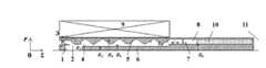
图1为背景技术【牛洪昌,钱宝良.紧凑型L波段同轴相对论返波振荡器的粒子模拟.强激光与粒子束,2006,Vol.18,No.11,pp.1879-1882】中公布的L波段同轴RBWO的结构示意图;Figure 1 is the background technology [Niu Hongchang, Qian Baoliang. Particle simulation of compact L-band coaxial relativistic return wave oscillator. Strong laser and particle beam, 2006, Vol.18, No.11, pp.1879-1882] Schematic diagram of the published L-band coaxial RBWO structure;
图2为背景技术【Evgeny M.Tot’meninov,Alexey I.Klimov,Ivan K.Kurkan,Sergei D.Polevin,and Vladislav V.Rostov.Repetitively Pulsed Relativistic BWO With EnhancedMechanical Frequency Tunability.IEEE Transactions on Plasma Science,2008,Vol.36,No.5,pp.2609-2612】中公布的频率可调RBWO结构示意图;Figure 2 is the background technology [Evgeny M.Tot'meninov, Alexey I.Klimov, Ivan K.Kurkan, Sergei D.Polevin, and Vladislav V.Rostov. Repetitively Pulsed Relativistic BWO With Enhanced Mechanical Frequency Tunability.IEEE Transactions on Plasma08 Science, , Vol.36, No.5, pp.2609-2612】Schematic diagram of the frequency-tunable RBWO structure;
图3为本发明中的紧凑型低频段频率可调RBWO的A-A剖视图;Fig. 3 is the A-A sectional view of the compact low-band frequency adjustable RBWO in the present invention;
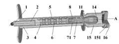
图4为本发明中的紧凑型低频段频率可调RBWO的整体结构图。Fig. 4 is the overall structure diagram of the compact low-band frequency adjustable RBWO in the present invention.
具体实施方式Detailed ways
图1为背景技术【牛洪昌,钱宝良.紧凑型L波段同轴相对论返波振荡器的粒子模拟.强激光与粒子束,2006,Vol.18,No.11,pp.1879-1882】中公布的L波段同轴RBWO的结构示意图。为了叙述的方便,将沿轴线方向上靠近阴极座的一侧称为左端,远离阴极座的一侧称为右端。该结构由阴极座1、阴极2、阳极外筒3、截止颈4、慢波结构5、内导体6、收集极7、微波输出口8、螺线管磁场9、吸波介质10、支撑杆11组成,整个结构关于中心轴线旋转对称。虽然该论文公布了该结构的组成,但该结构只是初步建立的数值仿真模型,没有具体技术方案,下面只是简要介绍本结构的大致连接关系。阴极座1左端外接脉冲功率源的内导体,阳极外筒3左端外接脉冲功率源的外导体。阴极2是一个薄壁圆筒,圆筒壁的厚度仅为0.1mm,内半径R1等于电子束的半径,套在阴极座1右端。截止颈4呈圆盘状,内半径为R2,R2>R1。慢波结构5由五个慢波叶片组成,每个慢波叶片的内表面均是正弦结构,最大外半径R4和最小内半径R5满足R4>R5>R2。慢波叶片的长度L1为工作波长λ的二分之一左右。截止颈4和慢波结构5从阳极外筒3的右侧沿轴向依次嵌入阳极外筒3并固定。内导体6是一个半径为R3的圆柱体,R3<R1。收集极7是一个半径为R6的圆柱体,收集极7左端面距离慢波结构右侧末端的距离为L2。支撑杆11是环形结构,外半径等于慢波叶片最大外半径R4,内半径等于收集极7的半径R6。内导体6和收集极7由支撑杆11支撑并从阳极外筒3的右端沿轴向嵌入阳极外筒3内固定。收集极7与阳极外筒3之间的圆环空间为微波输出口8。螺线管磁场9为仿真计算中设置的理想模型,通过设置电流大小和绕线匝数确定磁场大小。吸波介质10为仿真计算中设置的理想匹配负载,通过设置介电常数和长度实现对输出微波的匹配吸收。在RBWO运行时,阴极2产生的相对论电子束与慢波结构5和内导体6决定的最低阶模式(TEM模式)的电磁波进行束波相互作用,产生的高功率微波从微波输出口8输出。由于慢波结构5和内导体6组成的区域内电场的最低阶模式的截止频率为0,即对最低阶模式不截止,慢波叶片内半径R5和内导体6半径R3只需满足R5>R3,就可产生低频段高功率微波。该方案对慢波叶片外半径R4的大小没有限制,这对于缩小RBWO的径向尺寸有重要借鉴意义。但是,实际RBWO工作中,收集极7左端面距离慢波结构右侧末端的距离L2只有2cm,电子直接轰击收集极7左端面容易产生二次电子发射,影响微波的提取。此外,慢波结构5有五个正弦形状慢波叶片,其耦合阻抗较小,不利于提高器件的束波作用效率,并且加工难度大,不利于工程实现。此外,这种L波段同轴RBWO不具有频率可调节性。Figure 1 is the background technology [Niu Hongchang, Qian Baoliang. Particle simulation of compact L-band coaxial relativistic return wave oscillator. Strong laser and particle beam, 2006, Vol.18, No.11, pp.1879-1882] Schematic diagram of the published L-band coaxial RBWO structure. For the convenience of description, the side close to the cathode seat along the axis is called the left end, and the side far away from the cathode seat is called the right end. The structure consists of a
图2为背景技术【Evgeny M.Tot’meninov,Alexey I.Klimov,Ivan K.Kurkan,Sergei D.Polevin,and Vladislav V.Rostov.Repetitively Pulsed Relativistic BWO With EnhancedMechanical Frequency Tunability.IEEE Transactions on Plasma Science,2008,Vol.36,No.5,pp.2609-2612】中公布的频率机械可调RBWO频率结构示意图。该结构由阴极座1、阴极2、阳极外筒3、截止颈4、前置反射腔12、漂移段13、慢波结构5、微波输出口8、螺线管磁场9组成,整个结构关于中心轴线旋转对称。其中,阴极座1、阴极2、阳极外筒3、截止颈4、前置反射腔12、漂移段13、慢波结构5均为不锈钢材料,螺线管磁场9采用漆包铜线绕制而成。阴极座1左端外接脉冲功率源的内导体,阳极外筒3左端外接脉冲功率源的外导体。阴极2是一个薄壁圆筒,壁厚仅为0.1mm,内半径R1等于电子束的半径,套在阴极座1右端。截止颈4呈圆盘状,内半径为R2,R2>R1。前置反射腔12呈圆盘状,内半径等于截止颈4内半径R2,外半径R7满足R7>R2。漂移段13也呈圆盘状,内半径等于截止颈4内半径R2,长度为L3。慢波结构5由八个慢波叶片组成,每个慢波叶片的内表面均是梯形结构,左侧三个慢波叶片完全相同,右侧五个慢波叶片完全相同,左侧慢波叶片的最大外半径R4、最小内半径R5与右侧慢波叶片的最大外半径R8、最小内半径R9满足R8>R4,R9>R5。八个慢波叶片的长度相同,均为L1,为工作波长λ的二分之一左右。截止颈4、前置反射腔12、漂移段13和慢波结构5从阳极外筒3的右侧沿轴向依次嵌入阳极外筒3并固定。慢波结构5右端与阳极外筒3之间的圆环空间为微波输出口8。螺线管磁场9为利用漆包线绕制而成的螺线管磁场,通过改变通电电流确定磁场大小。在该RBWO运行中,阴极2产生的相对论电子束与慢波结构5决定的最低阶模式(TM01模式)的电磁波进行束波相互作用,产生的高功率微波从微波输出口8输出。但要利用这种RBWO产生2GHz的低频段高功率微波,RBWO慢波叶片的径向半径R4至少要大于5.7cm,这样就增大了径向尺寸。此外,慢波结构5有八个慢波叶片组成,若应用在频率在2GHz以下的低频段,需要慢波结构的长度至少约为8倍的二分之一波长λ(超过60cm),大大增加了RBWO的轴向长度。RBWO体积和重量的增加使螺线管磁场9的体积和重量相应增加,给加工和实验带来较大困难。但此RBWO可通过调节漂移段13的长度L3以调节输出微波的频率。Figure 2 is the background technology [Evgeny M.Tot'meninov, Alexey I.Klimov, Ivan K.Kurkan, Sergei D.Polevin, and Vladislav V.Rostov. Repetitively Pulsed Relativistic BWO With Enhanced Mechanical Frequency Tunability. IEEE Transactions on Plasma Science, 2008 , Vol.36, No.5, pp.2609-2612】Published in the frequency mechanically adjustable RBWO frequency structure diagram. The structure is composed of a
图3为本发明紧凑型低频段频率可调RBWO的的A-A剖视图,图4为本发明的整体结构图。本发明由阴极座1、阴极2、阳极外筒3、截止颈4、慢波结构5、内导体6、收集极7、微波输出口8、螺线管磁场9、支撑杆11、模式转换器14、辐射口15和密封板16组成,整个结构关于中心轴线旋转对称。其中,阴极座1、阴极2、阳极外筒3、截止颈4、慢波结构5、内导体6、收集极7、微波输出口8、支撑杆11均为不锈钢材料,螺线管磁场9采用漆包铜线,模式转换器14、辐射口15为铝材料,密封板16为聚四氟乙烯材料。阴极座1左端外接脉冲功率源的内导体,阳极外筒3左端外接脉冲功率源的外导体。阴极2是一个薄壁圆筒,壁厚仅为0.1mm,内半径R1等于电子束的半径,套在阴极座1右端。截止颈4呈圆盘状,内半径为R2,R2>R1。慢波结构5由五个慢波叶片组成,每个慢波叶片的内表面均是梯形结构,梯形结构的最大外半径R4与最小内半径R5满足R4>R5>R2,梯形结构的长度L1约为工作波长λ的二分之一。慢波叶片之间通过螺纹拧紧。截止颈4和慢波结构5从阳极外筒3的右侧,沿轴向、紧贴阳极外筒3的内壁,依次嵌入阳极外筒3并固定。内导体6是一个表面光滑的圆柱体,半径R3的变化对工作频率会产生影响,通过调节R3,可以调节本发明输出微波的频率。内导体6右端通过外螺纹与收集极7相连,左端沿轴向插入慢波结构5中央,且与慢波结构5同轴,内导体6的左端面与截止颈4的右端面平齐。收集极7为圆筒状,左端面挖有环形凹槽71,环形凹槽71的内半径R10和外半径R11根据阴极2的内半径R1来选取,满足R11>R1>R10,环形凹槽71的长度L4约为工作波长λ的三分之一。收集极7左端面的中心有外半径为R3的内螺纹,与内导体6右端的的外螺纹相连;收集极7右端是外半径为R6的圆筒,且带内螺纹,与模式转换器14的左端面相连。模式转换器14为圆筒状,左端开口且带外螺纹,右端为锥形结构(锥形角度90°<θ1<180°,90°<θ2<180°)。模式转换器14使RBWO产生的TEM模式的高功率微波转换成容易辐射的TM01模式的高功率微波。内导体6右端的外螺纹旋入收集极7左端面的内螺纹处,模式转换器14左端的外螺纹旋入收集极7右端的内螺纹处。支撑杆11共有两排,第一排支撑杆放在距离收集极7左端面为L5的位置,L5>L4;第二排支撑杆与第一排支撑杆之间的距离L6约为工作波长λ的四分之一;采用两排支撑杆既增强了支撑强度,又可以消除输出口对微波的反射。收集极7、模式转换器14由两排支撑杆11支撑,从阳极外筒3的右端沿轴向嵌入阳极外筒3内。其中,收集极7插入阳极外筒3中央且与阳极外筒3同轴,第一排支撑杆固定在距离收集极7左端面为L5的阳极外筒3的内壁上。辐射口15为圆筒状,左端为锥形结构(锥形角度0°<θ3<90°),锥形结构的起始位置与模式转换器14的起始位置平齐,锥形结构左端留有外螺纹,与阳极外筒3的右侧通过螺纹拧紧。辐射口15的右端为圆筒状,圆筒内半径为R12,R12>R6,辐射口的右端面挖有一个环形的密封槽151。。密封板16是一个圆盘,其利用抽真空时辐射口15内外的压力差,通过密封槽151压在辐射口15上。密封板16起保持RBWO内部真空环境的效果。收集极7与阳极外筒3之间的圆环空间为微波输出口8。本发明运行时,阴极2产生的相对论电子束与由慢波结构5和内导体6决定的最低阶模式(TEM模式)的电磁波进行束波相互作用,产生功率为1.15GW、频率为1.58GHz的L波段的高功率微波从微波,经模式转换器14转换成容易辐射的TM01模式的高功率微波,通过改变内导体6的半径R3可调节输出微波的工作频率。Fig. 3 is an AA cross-sectional view of the compact low-band frequency adjustable RBWO of the present invention, and Fig. 4 is an overall structure diagram of the present invention. The present invention consists of a
国防科技大学设计了中心频率为1.58GHz(对应微波波长λ=18.99cm)的紧凑型L波段频率可调RBWO。在强流加速器上开展了系统的实验研究,当导引磁场为0.85T、二极管电压为711kV、电流为11.6kA时,得到频率1.58GHz、功率1.15GW、脉宽40ns的微波输出,并且当内导体6的半径R3在0.5-1.75cm范围内改变时,微波频率在1.65-1.55GHz范围内可调。这是首次关于L波段RBWO的实验结果。此外,还进行了长脉冲实验研究,在导引磁场0.95T、二极管电压705kV的条件下,获得了频率1.58GHz、功率1.2GW、脉宽85ns的微波输出,结果表明器件具有长脉冲运行的潜力。由上述结果可知,本发明在结构紧凑的情况下实现了低频段、高功率微波的长脉冲输出,并且仅通过改变内导体半径R3就可实现对输出微波的频率进行调节。The National University of Defense Technology designed a compact L-band frequency-tunable RBWO with a center frequency of 1.58GHz (corresponding to microwave wavelength λ=18.99cm). A systematic experimental study has been carried out on a high-current accelerator. When the guiding magnetic field is 0.85T, the diode voltage is 711kV, and the current is 11.6kA, a microwave output with a frequency of 1.58GHz, a power of 1.15GW, and a pulse width of 40ns is obtained. When the radius R3 of the
Claims (4)
Priority Applications (1)
| Application Number | Priority Date | Filing Date | Title |
|---|---|---|---|
| CN2011101066661ACN102208315B (en) | 2011-04-26 | 2011-04-26 | Compact relativity backward wave oscillator (RBWO) with adjustable low-frequency-range frequency |
Applications Claiming Priority (1)
| Application Number | Priority Date | Filing Date | Title |
|---|---|---|---|
| CN2011101066661ACN102208315B (en) | 2011-04-26 | 2011-04-26 | Compact relativity backward wave oscillator (RBWO) with adjustable low-frequency-range frequency |
Publications (2)
| Publication Number | Publication Date |
|---|---|
| CN102208315A CN102208315A (en) | 2011-10-05 |
| CN102208315Btrue CN102208315B (en) | 2012-11-14 |
Family
ID=44697089
Family Applications (1)
| Application Number | Title | Priority Date | Filing Date |
|---|---|---|---|
| CN2011101066661AExpired - Fee RelatedCN102208315B (en) | 2011-04-26 | 2011-04-26 | Compact relativity backward wave oscillator (RBWO) with adjustable low-frequency-range frequency |
Country Status (1)
| Country | Link |
|---|---|
| CN (1) | CN102208315B (en) |
Families Citing this family (26)
| Publication number | Priority date | Publication date | Assignee | Title |
|---|---|---|---|---|
| CN102881544B (en)* | 2012-09-29 | 2015-07-29 | 成都智向科技有限公司 | A kind of longitudinal output gyrotron depressed collector electrode structure |
| CN103137399B (en)* | 2013-02-01 | 2015-11-18 | 中国人民解放军国防科学技术大学 | Coaxial-extraction long-pulse relativistic backward-wave oscillator |
| CN103456587B (en)* | 2013-09-11 | 2016-01-20 | 中国人民解放军国防科学技术大学 | Across wave band machinery frequency modulation Relativistic backward-wave oscillator |
| CN104320904B (en)* | 2014-10-21 | 2018-12-04 | 明建川 | Microwave electron accelerators |
| CN104362060B (en)* | 2014-11-25 | 2016-10-19 | 中国人民解放军国防科学技术大学 | A Dielectric Filled Compact Relativistic Flyback Oscillator |
| CN105489460B (en)* | 2015-12-16 | 2017-07-11 | 中国工程物理研究院应用电子学研究所 | A kind of coaxial Relativistic backward-wave oscillator of K-band |
| CN105529234B (en)* | 2016-01-19 | 2017-03-15 | 中国人民解放军国防科学技术大学 | A kind of X, Ku wave band is adjustable high-power microwave source |
| CN105719925B (en)* | 2016-04-22 | 2017-05-24 | 中国人民解放军国防科学技术大学 | High band magnetically insulated transmission line oscillator |
| CN105869971B (en)* | 2016-05-23 | 2017-11-21 | 电子科技大学 | A kind of flat-head type sine waveguide slow-wave structure |
| CN106098510B (en)* | 2016-07-04 | 2018-03-16 | 中国工程物理研究院应用电子学研究所 | A kind of repetition downfield axial direction C-band high-power pulsed ion beams |
| CN106449337B (en)* | 2016-08-12 | 2018-01-12 | 中国人民解放军国防科学技术大学 | A kind of long pulse Relativistic backward-wave oscillator |
| CN106253031B (en)* | 2016-08-12 | 2018-09-21 | 中国人民解放军国防科学技术大学 | Submicrosecond grade long pulse high efficiency the theory of relativity Cherenkov's oscillator |
| CN106298406B (en)* | 2016-08-29 | 2018-01-12 | 中国工程物理研究院应用电子学研究所 | The processing method and tool of slow-wave structure in Relativistic backward-wave oscillator |
| CN106531598B (en)* | 2016-11-07 | 2018-01-30 | 中国人民解放军国防科学技术大学 | Can mechanical frequency modulation L-band transit-time oscillator |
| CN108682605B (en)* | 2018-05-21 | 2020-01-31 | 中国工程物理研究院应用电子学研究所 | coupled two-cavity high-power microwave generator and use method thereof |
| CN109148242B (en)* | 2018-10-15 | 2020-04-14 | 电子科技大学 | An electromagnetic wave oscillator |
| CN109524283B (en)* | 2018-12-10 | 2020-09-18 | 中国工程物理研究院应用电子学研究所 | Compact high-power microwave device with dual-waveband low-guiding magnetic field |
| CN110718426B (en)* | 2019-09-27 | 2021-10-26 | 中国工程物理研究院应用电子学研究所 | High-frequency high-power microwave device |
| CN110718428B (en)* | 2019-09-27 | 2021-10-26 | 中国工程物理研究院应用电子学研究所 | 4 millimeter wave high-power microwave device |
| CN111584330B (en)* | 2020-05-21 | 2023-05-23 | 中国人民解放军国防科技大学 | Cerenkov microwave generator with frequency converted in C, X wave band |
| CN112038208B (en)* | 2020-09-08 | 2022-04-15 | 中国人民解放军国防科技大学 | Ka-band coaxial transit time oscillator with trapezoidal structure |
| CN112687504B (en)* | 2020-12-24 | 2022-02-22 | 西安交通大学 | Double-electron-beam relativistic backward wave tube capable of directly outputting double-frequency microwaves |
| CN112769024B (en)* | 2021-01-27 | 2021-11-19 | 中国人民解放军国防科技大学 | C-band relativistic Cerenkov oscillator with coaxial collector |
| CN112885681B (en)* | 2021-01-28 | 2022-05-03 | 电子科技大学 | A Relativistic Magnetron with Double-Terminal Emitting Cathode Structure |
| CN113053707B (en)* | 2021-03-18 | 2022-07-22 | 电子科技大学 | Double-frequency relativistic backward wave tube using plasma cathode electron gun |
| CN115954249B (en)* | 2022-12-16 | 2024-11-29 | 电子科技大学 | A coaxial relativistic backward wave tube based on superradiance mechanism |
Citations (3)
| Publication number | Priority date | Publication date | Assignee | Title |
|---|---|---|---|---|
| GB776215A (en)* | 1954-05-13 | 1957-06-05 | Csf | Improvements in or relating to electron discharge tubes with crossed electric and magnetic fields |
| US7037370B2 (en)* | 2003-02-06 | 2006-05-02 | Mearini Gerald T | Free-standing diamond structures and methods |
| CN201629290U (en)* | 2009-12-22 | 2010-11-10 | 中国工程物理研究院应用电子学研究所 | Tunable backward wave tube |
- 2011
- 2011-04-26CNCN2011101066661Apatent/CN102208315B/ennot_activeExpired - Fee Related
Patent Citations (3)
| Publication number | Priority date | Publication date | Assignee | Title |
|---|---|---|---|---|
| GB776215A (en)* | 1954-05-13 | 1957-06-05 | Csf | Improvements in or relating to electron discharge tubes with crossed electric and magnetic fields |
| US7037370B2 (en)* | 2003-02-06 | 2006-05-02 | Mearini Gerald T | Free-standing diamond structures and methods |
| CN201629290U (en)* | 2009-12-22 | 2010-11-10 | 中国工程物理研究院应用电子学研究所 | Tunable backward wave tube |
Also Published As
| Publication number | Publication date |
|---|---|
| CN102208315A (en) | 2011-10-05 |
Similar Documents
| Publication | Publication Date | Title |
|---|---|---|
| CN102208315B (en) | Compact relativity backward wave oscillator (RBWO) with adjustable low-frequency-range frequency | |
| CN103456587B (en) | Across wave band machinery frequency modulation Relativistic backward-wave oscillator | |
| CN103137399B (en) | Coaxial-extraction long-pulse relativistic backward-wave oscillator | |
| CN106449337B (en) | A kind of long pulse Relativistic backward-wave oscillator | |
| CN109192640B (en) | X, Ka-waveband-crossing frequency-adjustable relativistic backward wave oscillator | |
| CN106253031B (en) | Submicrosecond grade long pulse high efficiency the theory of relativity Cherenkov's oscillator | |
| CN105529234B (en) | A kind of X, Ku wave band is adjustable high-power microwave source | |
| CN105161390B (en) | New meta-materials high-power microwave source | |
| CN105810537B (en) | Using the X-band high impedance relativistic klystron amplifier of annular beam cold cathode | |
| CN111584330B (en) | Cerenkov microwave generator with frequency converted in C, X wave band | |
| CN115295380B (en) | A high-efficiency compact coaxial relativistic klystron amplifier with four-level modulation | |
| Yamaguchi et al. | High power 303 GHz gyrotron for CTS in LHD | |
| CN106653525A (en) | Millimeter waveband transition time oscillator based on high order mode working mechanism | |
| CN109616393A (en) | A kind of low guidance magnetic field compact high power microwave device of L-band | |
| CN109148244B (en) | Axially tunable relativistic magnetron | |
| CN109524283B (en) | Compact high-power microwave device with dual-waveband low-guiding magnetic field | |
| CN110806148B (en) | Compact narrow-band high-power microwave source for forced parking of vehicles and ships | |
| CN110718429A (en) | Double-frequency three-cavity high-power microwave device | |
| CN106783476B (en) | A kind of radially continuous wave Terahertz of double frequency tiltedly notes pipe | |
| CN109585242B (en) | A dual frequency high power microwave generator | |
| CN108831815B (en) | Periodic dielectric medium filled coaxial high-power microwave device | |
| CN108807112B (en) | Coaxial double-dielectric interdigital arrangement high-power microwave device | |
| CN110718431A (en) | L-band three-cavity high-power microwave device | |
| CN104901145A (en) | Continuous-wave terahertz surface wave oscillator | |
| CN116453920A (en) | K-band transit time oscillator based on two-stage modulation and distributed extraction |
Legal Events
| Date | Code | Title | Description |
|---|---|---|---|
| C06 | Publication | ||
| PB01 | Publication | ||
| C10 | Entry into substantive examination | ||
| SE01 | Entry into force of request for substantive examination | ||
| C14 | Grant of patent or utility model | ||
| GR01 | Patent grant | ||
| CF01 | Termination of patent right due to non-payment of annual fee | Granted publication date:20121114 | |
| CF01 | Termination of patent right due to non-payment of annual fee |