CN102202605A - Prophylactic pancreatic stent - Google Patents
Prophylactic pancreatic stentDownload PDFInfo
- Publication number
- CN102202605A CN102202605ACN200980142221XACN200980142221ACN102202605ACN 102202605 ACN102202605 ACN 102202605ACN 200980142221X ACN200980142221X ACN 200980142221XACN 200980142221 ACN200980142221 ACN 200980142221ACN 102202605 ACN102202605 ACN 102202605A
- Authority
- CN
- China
- Prior art keywords
- proximal
- stent
- canopies
- support
- distal
- Prior art date
- Legal status (The legal status is an assumption and is not a legal conclusion. Google has not performed a legal analysis and makes no representation as to the accuracy of the status listed.)
- Pending
Links
- 230000000069prophylactic effectEffects0.000titledescription7
- 238000000034methodMethods0.000claimsabstractdescription25
- 239000012530fluidSubstances0.000claimsabstractdescription13
- 238000004891communicationMethods0.000claimsabstractdescription7
- 239000000463materialSubstances0.000claimsdescription17
- -1polyethylenePolymers0.000claimsdescription9
- 238000002513implantationMethods0.000claimsdescription5
- JOYRKODLDBILNP-UHFFFAOYSA-NEthyl urethaneChemical compoundCCOC(N)=OJOYRKODLDBILNP-UHFFFAOYSA-N0.000claimsdescription3
- 239000004698PolyethyleneSubstances0.000claimsdescription3
- 210000001819pancreatic juiceAnatomy0.000claimsdescription3
- 229920000573polyethylenePolymers0.000claimsdescription3
- 229920001296polysiloxanePolymers0.000claimsdescription3
- 229920001343polytetrafluoroethylenePolymers0.000claimsdescription3
- 239000004810polytetrafluoroethyleneSubstances0.000claimsdescription3
- 239000004793PolystyreneSubstances0.000claimsdescription2
- 229920001400block copolymerPolymers0.000claimsdescription2
- 229920002223polystyrenePolymers0.000claimsdescription2
- GOLXNESZZPUPJE-UHFFFAOYSA-NspiromesifenChemical compoundCC1=CC(C)=CC(C)=C1C(C(O1)=O)=C(OC(=O)CC(C)(C)C)C11CCCC1GOLXNESZZPUPJE-UHFFFAOYSA-N0.000claims3
- 230000002265preventionEffects0.000claims2
- 239000004812Fluorinated ethylene propyleneSubstances0.000claims1
- 229920009441perflouroethylene propylenePolymers0.000claims1
- 239000004033plasticSubstances0.000claims1
- 229920003023plasticPolymers0.000claims1
- 230000001681protective effectEffects0.000claims1
- 210000000277pancreatic ductAnatomy0.000description53
- 210000000013bile ductAnatomy0.000description10
- 210000001953common bile ductAnatomy0.000description9
- 210000003445biliary tractAnatomy0.000description7
- 150000001252acrylic acid derivativesChemical class0.000description5
- 210000001198duodenumAnatomy0.000description5
- 230000007794irritationEffects0.000description5
- 206010033645PancreatitisDiseases0.000description4
- 239000000994contrast dyeSubstances0.000description4
- 210000004141ampulla of vaterAnatomy0.000description3
- 239000001913celluloseSubstances0.000description3
- 229920002678cellulosePolymers0.000description3
- 239000007943implantSubstances0.000description3
- 210000000496pancreasAnatomy0.000description3
- 229920000642polymerPolymers0.000description3
- 229920002635polyurethanePolymers0.000description3
- 239000004814polyurethaneSubstances0.000description3
- 210000001519tissueAnatomy0.000description3
- LYCAIKOWRPUZTN-UHFFFAOYSA-NEthylene glycolChemical compoundOCCOLYCAIKOWRPUZTN-UHFFFAOYSA-N0.000description2
- 239000002202Polyethylene glycolSubstances0.000description2
- 239000011248coating agentSubstances0.000description2
- 238000000576coating methodMethods0.000description2
- 238000007459endoscopic retrograde cholangiopancreatographyMethods0.000description2
- 210000000232gallbladderAnatomy0.000description2
- 238000002347injectionMethods0.000description2
- 239000007924injectionSubstances0.000description2
- 230000014759maintenance of locationEffects0.000description2
- 229920002627poly(phosphazenes)Polymers0.000description2
- 229920000728polyesterPolymers0.000description2
- 229920006149polyester-amide block copolymerPolymers0.000description2
- 229920000570polyetherPolymers0.000description2
- 229920001223polyethylene glycolPolymers0.000description2
- 229920001282polysaccharidePolymers0.000description2
- 239000005017polysaccharideSubstances0.000description2
- 150000004804polysaccharidesChemical class0.000description2
- 150000003839saltsChemical class0.000description2
- 230000000007visual effectEffects0.000description2
- KIUKXJAPPMFGSW-DNGZLQJQSA-N(2S,3S,4S,5R,6R)-6-[(2S,3R,4R,5S,6R)-3-Acetamido-2-[(2S,3S,4R,5R,6R)-6-[(2R,3R,4R,5S,6R)-3-acetamido-2,5-dihydroxy-6-(hydroxymethyl)oxan-4-yl]oxy-2-carboxy-4,5-dihydroxyoxan-3-yl]oxy-5-hydroxy-6-(hydroxymethyl)oxan-4-yl]oxy-3,4,5-trihydroxyoxane-2-carboxylic acidChemical compoundCC(=O)N[C@H]1[C@H](O)O[C@H](CO)[C@@H](O)[C@@H]1O[C@H]1[C@H](O)[C@@H](O)[C@H](O[C@H]2[C@@H]([C@@H](O[C@H]3[C@@H]([C@@H](O)[C@H](O)[C@H](O3)C(O)=O)O)[C@H](O)[C@@H](CO)O2)NC(C)=O)[C@@H](C(O)=O)O1KIUKXJAPPMFGSW-DNGZLQJQSA-N0.000description1
- KXJGSNRAQWDDJT-UHFFFAOYSA-N1-acetyl-5-bromo-2h-indol-3-oneChemical compoundBrC1=CC=C2N(C(=O)C)CC(=O)C2=C1KXJGSNRAQWDDJT-UHFFFAOYSA-N0.000description1
- QRIMLDXJAPZHJE-UHFFFAOYSA-N2,3-dihydroxypropyl 2-methylprop-2-enoateChemical compoundCC(=C)C(=O)OCC(O)COQRIMLDXJAPZHJE-UHFFFAOYSA-N0.000description1
- SMZOUWXMTYCWNB-UHFFFAOYSA-N2-(2-methoxy-5-methylphenyl)ethanamineChemical compoundCOC1=CC=C(C)C=C1CCNSMZOUWXMTYCWNB-UHFFFAOYSA-N0.000description1
- NIXOWILDQLNWCW-UHFFFAOYSA-N2-Propenoic acidNatural productsOC(=O)C=CNIXOWILDQLNWCW-UHFFFAOYSA-N0.000description1
- BKBSGDFMEPRLDG-UHFFFAOYSA-N2-[2-(2-hydroxyethoxy)ethoxy]-1-methoxyethanolChemical compoundCOC(O)COCCOCCOBKBSGDFMEPRLDG-UHFFFAOYSA-N0.000description1
- SHJIJMBTDZCOFE-UHFFFAOYSA-N2-[2-[2-(2-hydroxyethoxy)ethoxy]ethoxy]-1-methoxyethanolChemical compoundCOC(O)COCCOCCOCCOSHJIJMBTDZCOFE-UHFFFAOYSA-N0.000description1
- KGIGUEBEKRSTEW-UHFFFAOYSA-N2-vinylpyridineChemical compoundC=CC1=CC=CC=N1KGIGUEBEKRSTEW-UHFFFAOYSA-N0.000description1
- 241000191291Abies albaSpecies0.000description1
- HRPVXLWXLXDGHG-UHFFFAOYSA-NAcrylamideChemical compoundNC(=O)C=CHRPVXLWXLXDGHG-UHFFFAOYSA-N0.000description1
- NIXOWILDQLNWCW-UHFFFAOYSA-MAcrylateChemical compound[O-]C(=O)C=CNIXOWILDQLNWCW-UHFFFAOYSA-M0.000description1
- NLHHRLWOUZZQLW-UHFFFAOYSA-NAcrylonitrileChemical compoundC=CC#NNLHHRLWOUZZQLW-UHFFFAOYSA-N0.000description1
- 229920000856AmylosePolymers0.000description1
- 229920002134Carboxymethyl cellulosePolymers0.000description1
- 102000011632CaseinsHuman genes0.000description1
- 108010076119CaseinsProteins0.000description1
- 229920002101ChitinPolymers0.000description1
- 102000008186CollagenHuman genes0.000description1
- 108010035532CollagenProteins0.000description1
- 229920002307DextranPolymers0.000description1
- 239000004593EpoxySubstances0.000description1
- 239000001856Ethyl celluloseSubstances0.000description1
- ZZSNKZQZMQGXPY-UHFFFAOYSA-NEthyl celluloseChemical compoundCCOCC1OC(OC)C(OCC)C(OCC)C1OC1C(O)C(O)C(OC)C(CO)O1ZZSNKZQZMQGXPY-UHFFFAOYSA-N0.000description1
- IAYPIBMASNFSPL-UHFFFAOYSA-NEthylene oxideChemical compoundC1CO1IAYPIBMASNFSPL-UHFFFAOYSA-N0.000description1
- 102000009123FibrinHuman genes0.000description1
- 108010073385FibrinProteins0.000description1
- BWGVNKXGVNDBDI-UHFFFAOYSA-NFibrin monomerChemical compoundCNC(=O)CNC(=O)CNBWGVNKXGVNDBDI-UHFFFAOYSA-N0.000description1
- 102000008946FibrinogenHuman genes0.000description1
- 108010049003FibrinogenProteins0.000description1
- 108010010803GelatinProteins0.000description1
- HTTJABKRGRZYRN-UHFFFAOYSA-NHeparinChemical compoundOC1C(NC(=O)C)C(O)OC(COS(O)(=O)=O)C1OC1C(OS(O)(=O)=O)C(O)C(OC2C(C(OS(O)(=O)=O)C(OC3C(C(O)C(O)C(O3)C(O)=O)OS(O)(=O)=O)C(CO)O2)NS(O)(=O)=O)C(C(O)=O)O1HTTJABKRGRZYRN-UHFFFAOYSA-N0.000description1
- WOBHKFSMXKNTIM-UHFFFAOYSA-NHydroxyethyl methacrylateChemical compoundCC(=C)C(=O)OCCOWOBHKFSMXKNTIM-UHFFFAOYSA-N0.000description1
- 229920001612Hydroxyethyl starchPolymers0.000description1
- WHNWPMSKXPGLAX-UHFFFAOYSA-NN-Vinyl-2-pyrrolidoneChemical compoundC=CN1CCCC1=OWHNWPMSKXPGLAX-UHFFFAOYSA-N0.000description1
- 206010030113OedemaDiseases0.000description1
- 206010033647Pancreatitis acuteDiseases0.000description1
- 229920003171Poly (ethylene oxide)Polymers0.000description1
- 239000004952PolyamideSubstances0.000description1
- 229920002732PolyanhydridePolymers0.000description1
- 229920000954PolyglycolidePolymers0.000description1
- 239000004721Polyphenylene oxideSubstances0.000description1
- 239000004373PullulanSubstances0.000description1
- 229920001218PullulanPolymers0.000description1
- 229920002472StarchPolymers0.000description1
- 201000003229acute pancreatitisDiseases0.000description1
- 239000000783alginic acidSubstances0.000description1
- 235000010443alginic acidNutrition0.000description1
- 229920000615alginic acidPolymers0.000description1
- 229960001126alginic acidDrugs0.000description1
- 150000004781alginic acidsChemical class0.000description1
- 210000003484anatomyAnatomy0.000description1
- 238000001574biopsyMethods0.000description1
- 239000001768carboxy methyl celluloseSubstances0.000description1
- 235000010948carboxy methyl celluloseNutrition0.000description1
- 239000008112carboxymethyl-celluloseSubstances0.000description1
- 239000005018caseinSubstances0.000description1
- BECPQYXYKAMYBN-UHFFFAOYSA-Ncasein, tech.Chemical compoundNCCCCC(C(O)=O)N=C(O)C(CC(O)=O)N=C(O)C(CCC(O)=N)N=C(O)C(CC(C)C)N=C(O)C(CCC(O)=O)N=C(O)C(CC(O)=O)N=C(O)C(CCC(O)=O)N=C(O)C(C(C)O)N=C(O)C(CCC(O)=N)N=C(O)C(CCC(O)=N)N=C(O)C(CCC(O)=N)N=C(O)C(CCC(O)=O)N=C(O)C(CCC(O)=O)N=C(O)C(COP(O)(O)=O)N=C(O)C(CCC(O)=N)N=C(O)C(N)CC1=CC=CC=C1BECPQYXYKAMYBN-UHFFFAOYSA-N0.000description1
- 235000021240caseinsNutrition0.000description1
- 229920002301cellulose acetatePolymers0.000description1
- 229920001436collagenPolymers0.000description1
- 238000010276constructionMethods0.000description1
- 229920001577copolymerPolymers0.000description1
- 210000001096cystic ductAnatomy0.000description1
- 230000006866deteriorationEffects0.000description1
- 238000010586diagramMethods0.000description1
- 239000000975dyeSubstances0.000description1
- 238000001839endoscopyMethods0.000description1
- 238000005516engineering processMethods0.000description1
- 229920001249ethyl cellulosePolymers0.000description1
- 235000019325ethyl celluloseNutrition0.000description1
- 229950003499fibrinDrugs0.000description1
- 229940012952fibrinogenDrugs0.000description1
- 238000002594fluoroscopyMethods0.000description1
- 210000001035gastrointestinal tractAnatomy0.000description1
- 229920000159gelatinPolymers0.000description1
- 239000008273gelatinSubstances0.000description1
- 229940014259gelatinDrugs0.000description1
- 235000019322gelatineNutrition0.000description1
- 235000011852gelatine dessertsNutrition0.000description1
- 229920000669heparinPolymers0.000description1
- 229960002897heparinDrugs0.000description1
- 229920001519homopolymerPolymers0.000description1
- 229920002674hyaluronanPolymers0.000description1
- 229960003160hyaluronic acidDrugs0.000description1
- WGCNASOHLSPBMP-UHFFFAOYSA-NhydroxyacetaldehydeNatural productsOCC=OWGCNASOHLSPBMP-UHFFFAOYSA-N0.000description1
- 229940050526hydroxyethylstarchDrugs0.000description1
- 208000014674injuryDiseases0.000description1
- 239000000976inkSubstances0.000description1
- 230000001050lubricating effectEffects0.000description1
- 239000003550markerSubstances0.000description1
- 210000001595mastoidAnatomy0.000description1
- 239000002184metalSubstances0.000description1
- 229920000609methyl cellulosePolymers0.000description1
- 239000001923methylcelluloseSubstances0.000description1
- 239000000203mixtureSubstances0.000description1
- 238000012986modificationMethods0.000description1
- 230000004048modificationEffects0.000description1
- 239000000178monomerSubstances0.000description1
- 238000000465mouldingMethods0.000description1
- 150000002905orthoestersChemical class0.000description1
- 239000001814pectinSubstances0.000description1
- 235000010987pectinNutrition0.000description1
- 229920001277pectinPolymers0.000description1
- 229920001308poly(aminoacid)Polymers0.000description1
- 229920002463poly(p-dioxanone) polymerPolymers0.000description1
- 229920002647polyamidePolymers0.000description1
- 229920001610polycaprolactonePolymers0.000description1
- 229920000515polycarbonatePolymers0.000description1
- 239000004417polycarbonateSubstances0.000description1
- 229920002643polyglutamic acidPolymers0.000description1
- 239000004633polyglycolic acidSubstances0.000description1
- 229920001228polyisocyanatePolymers0.000description1
- 239000005056polyisocyanateSubstances0.000description1
- 229920000656polylysinePolymers0.000description1
- 229920000166polytrimethylene carbonatePolymers0.000description1
- 230000002980postoperative effectEffects0.000description1
- KCXFHTAICRTXLI-UHFFFAOYSA-Npropane-1-sulfonic acidChemical compoundCCCS(O)(=O)=OKCXFHTAICRTXLI-UHFFFAOYSA-N0.000description1
- 235000019423pullulanNutrition0.000description1
- 239000008107starchSubstances0.000description1
- 235000019698starchNutrition0.000description1
- 239000004575stoneSubstances0.000description1
- 239000000126substanceSubstances0.000description1
- 238000002627tracheal intubationMethods0.000description1
- 230000008733traumaEffects0.000description1
- 230000002792vascularEffects0.000description1
- 238000003466weldingMethods0.000description1
Images


Classifications
- A—HUMAN NECESSITIES
- A61—MEDICAL OR VETERINARY SCIENCE; HYGIENE
- A61M—DEVICES FOR INTRODUCING MEDIA INTO, OR ONTO, THE BODY; DEVICES FOR TRANSDUCING BODY MEDIA OR FOR TAKING MEDIA FROM THE BODY; DEVICES FOR PRODUCING OR ENDING SLEEP OR STUPOR
- A61M25/00—Catheters; Hollow probes
- A—HUMAN NECESSITIES
- A61—MEDICAL OR VETERINARY SCIENCE; HYGIENE
- A61F—FILTERS IMPLANTABLE INTO BLOOD VESSELS; PROSTHESES; DEVICES PROVIDING PATENCY TO, OR PREVENTING COLLAPSING OF, TUBULAR STRUCTURES OF THE BODY, e.g. STENTS; ORTHOPAEDIC, NURSING OR CONTRACEPTIVE DEVICES; FOMENTATION; TREATMENT OR PROTECTION OF EYES OR EARS; BANDAGES, DRESSINGS OR ABSORBENT PADS; FIRST-AID KITS
- A61F2/00—Filters implantable into blood vessels; Prostheses, i.e. artificial substitutes or replacements for parts of the body; Appliances for connecting them with the body; Devices providing patency to, or preventing collapsing of, tubular structures of the body, e.g. stents
- A61F2/02—Prostheses implantable into the body
- A61F2/04—Hollow or tubular parts of organs, e.g. bladders, tracheae, bronchi or bile ducts
- A—HUMAN NECESSITIES
- A61—MEDICAL OR VETERINARY SCIENCE; HYGIENE
- A61M—DEVICES FOR INTRODUCING MEDIA INTO, OR ONTO, THE BODY; DEVICES FOR TRANSDUCING BODY MEDIA OR FOR TAKING MEDIA FROM THE BODY; DEVICES FOR PRODUCING OR ENDING SLEEP OR STUPOR
- A61M27/00—Drainage appliance for wounds or the like, i.e. wound drains, implanted drains
- A61M27/002—Implant devices for drainage of body fluids from one part of the body to another
- A61M27/008—Implant devices for drainage of body fluids from one part of the body to another pre-shaped, for use in the urethral or ureteral tract
- A—HUMAN NECESSITIES
- A61—MEDICAL OR VETERINARY SCIENCE; HYGIENE
- A61F—FILTERS IMPLANTABLE INTO BLOOD VESSELS; PROSTHESES; DEVICES PROVIDING PATENCY TO, OR PREVENTING COLLAPSING OF, TUBULAR STRUCTURES OF THE BODY, e.g. STENTS; ORTHOPAEDIC, NURSING OR CONTRACEPTIVE DEVICES; FOMENTATION; TREATMENT OR PROTECTION OF EYES OR EARS; BANDAGES, DRESSINGS OR ABSORBENT PADS; FIRST-AID KITS
- A61F2/00—Filters implantable into blood vessels; Prostheses, i.e. artificial substitutes or replacements for parts of the body; Appliances for connecting them with the body; Devices providing patency to, or preventing collapsing of, tubular structures of the body, e.g. stents
- A61F2/82—Devices providing patency to, or preventing collapsing of, tubular structures of the body, e.g. stents
- A61F2/94—Stents retaining their form, i.e. not being deformable, after placement in the predetermined place
Landscapes
- Health & Medical Sciences (AREA)
- Life Sciences & Earth Sciences (AREA)
- General Health & Medical Sciences (AREA)
- Public Health (AREA)
- Animal Behavior & Ethology (AREA)
- Veterinary Medicine (AREA)
- Engineering & Computer Science (AREA)
- Biomedical Technology (AREA)
- Heart & Thoracic Surgery (AREA)
- Hematology (AREA)
- Pulmonology (AREA)
- Anesthesiology (AREA)
- Cardiology (AREA)
- Gastroenterology & Hepatology (AREA)
- Vascular Medicine (AREA)
- Oral & Maxillofacial Surgery (AREA)
- Transplantation (AREA)
- Biophysics (AREA)
- Urology & Nephrology (AREA)
- Ophthalmology & Optometry (AREA)
- Otolaryngology (AREA)
- Media Introduction/Drainage Providing Device (AREA)
- Prostheses (AREA)
- Materials For Medical Uses (AREA)
Abstract
Translated fromChinese
Description
Translated fromChinese相关申请related application
本申请要求2008年10月22日提交的美国临时申请No.61/107,502的利益,其全文结合于此。This application claims the benefit of US Provisional Application No. 61/107,502, filed October 22, 2008, which is hereby incorporated in its entirety.
技术领域technical field
本发明基本涉及可植入患者身体之内的脉管或管道中的支架,并且尤其涉及可以用来在医疗程序(medical procedure)中保护脉管或管道的支架。The present invention generally relates to stents implantable in vessels or conduits within a patient's body, and more particularly to stents that may be used to protect vessels or conduits during medical procedures.
背景技术Background technique
微创医疗程序在身体的各种脉管和管道中进行。在某些程序中,可能需要到达脉管或管道,以便设置假体设备,获得活检标本,或者移除组织材料或其它物质。Minimally invasive medical procedures are performed in various vessels and ducts of the body. During certain procedures, it may be necessary to access a vessel or duct in order to place a prosthetic device, obtain a biopsy specimen, or to remove tissue material or other substances.
微创医疗程序经常在胆管系统中进行。进入胆管系统要经过十二指肠进入到法特氏壶腹(Ampulla ofVater),该法特氏壶腹通向用于胰管或者胆总管(CBD)和胆囊的支管(branch)。在多数程序中,进入CBD通过利用括约式导管(sphincterotome catheter)或ERCP导管进行插管而实现,从而进入胆管。典型地,在导管管腔之内预设导线。一旦插管成功进行,内科医生就可以使导线进一步前进到CBD内。扩约式或ERCP导管可以被撤走,并且另一个设备可以越过导线前进而进入CBD,例如胆支架、取石球囊或网篮等。从乳突、CBD和胰管的解剖来看,使导管/导线前进进入到胆管可能相当困难。通常,内科医生会碰巧使导管/导线前进进入到胰管内。对于没有经验的内窥镜医生,可能需要尝试多次才能进入到胰管内。单次或者反复地将进入胰管的导管/导线放错位置会引起水肿或者使创伤恶化,这就会妨碍胰液引流。对于胰管的损伤会导致术后胰腺炎,一种相当痛苦且潜在致命的病症。Minimally invasive medical procedures are often performed in the biliary system. Access to the biliary system is via the duodenum into the Ampulla of Vater, which leads to the branches for the pancreatic or common bile duct (CBD) and gallbladder. In most procedures, access to the CBD is achieved by cannulation with a sphincterotome catheter or ERCP catheter to access the bile duct. Typically, a guidewire is preset within the lumen of the catheter. Once intubation has been successfully performed, the physician may advance the lead further into the CBD. The expandable or ERCP catheter can be withdrawn and another device can be advanced over the wire into the CBD, such as a biliary stent, stone retrieval balloon, or mesh basket. Advancing the catheter/guide into the bile duct can be quite difficult in view of the anatomy of the mastoid, CBD, and pancreatic duct. Often, the physician will happen to advance the catheter/wire into the pancreatic duct. For an inexperienced endoscopist, several attempts may be required to gain access to the pancreatic duct. Single or repeated misplacement of the catheter/wire into the pancreatic duct can cause edema or worsen the trauma, which can prevent pancreatic juice drainage. Damage to the pancreatic duct can lead to postoperative pancreatitis, a rather painful and potentially fatal condition.
需要一种方法和一种支架,当在胆管系统中进行微创医疗程序时,其能够预防性地减少或阻止急性胰腺炎。此外,所述预防支架可以有助于无经验的内窥镜医生,并有助于减少在胆管系统之内进行程序的时间并降低其复杂性。该支架可以不产生创伤地设置在胰管之内并保持就位,而不会引起管道组织的恶化,并且可以防止在以胆管为预期目标时意外进入胰管。该支架可以临时放置,并且可以在对管道产生轻微损伤或额外刺激的情况下被移除。There is a need for a method and a stent capable of prophylactically reducing or preventing acute pancreatitis when performing minimally invasive medical procedures in the biliary system. Furthermore, the prophylactic stent can assist inexperienced endoscopists and help reduce the time and complexity of procedures within the biliary system. The stent can be placed atraumatically within the pancreatic duct and remains in place without causing deterioration of the duct tissue and prevents accidental entry into the pancreatic duct when the bile duct is the intended target. The stent can be placed temporarily and can be removed with minor damage to the duct or additional irritation.
发明内容Contents of the invention
相应地,本发明的目的是提供一种方法和一种支架,其具有解决或改进一个或一个以上上述缺点的特征。Accordingly, it is an object of the present invention to provide a method and a stent characterized in that it solves or improves one or more of the aforementioned disadvantages.
在本发明的一个方面,通过提供一种用于预防性地保护管道的支架而获得前述目的。所述支架包括不能够扩张的基本管状本体,所述本体具有近侧部分和远侧部分,管腔经过所述本体的至少一部分延伸,在所述远侧部分中的远侧开口与所述管腔流体连通,并且在所述近侧部分中的近侧开口与所述管腔流体连通。所述支架进一步包括冠盖部分,所述冠盖部分能够操作地连接到所述本体的近侧部分,并且能够在非扩张配置和扩张配置之间活动。所述非扩张配置具有缩小直径,以便于前进到患者内,并且所述扩张配置具有扩张直径,所述扩张直径配置为保护体内管道的开口,从而防止长型医疗设备意外地经过所述开口并进入到所述体内管道的通道内。In one aspect of the present invention, the foregoing objects are achieved by providing a brace for prophylactic protection of pipelines. The stent comprises a non-expandable substantially tubular body having a proximal portion and a distal portion through which a lumen extends at least a portion of the body, a distal opening in the distal portion being connected to the tube The lumen is in fluid communication, and a proximal opening in the proximal portion is in fluid communication with the lumen. The stent further includes a cap portion operatively connected to the proximal portion of the body and movable between a non-expanded configuration and an expanded configuration. The non-expanded configuration has a reduced diameter to facilitate advancement into the patient, and the expanded configuration has an expanded diameter configured to protect openings of internal conduits to prevent accidental passage of elongated medical devices through the openings and into the channel of the body duct.
在本发明的另一个方面,提供了一种用于在管道中植入预防支架的方法。所述方法包括:利用导线进入支管系统,使所述导线前进到所述支管系统的第一管道内,并且使支架越过所述导线前进。所述支架包括不能够扩张的基本管状本体,所述本体具有近侧部分和远侧部分,管腔经过所述本体的至少一部分延伸,在所述远侧部分中的远侧开口与所述管腔流体连通,并且在所述近侧部分中的近侧开口与所述管腔流体连通。所述支架进一步包括冠盖部分,所述冠盖部分能够操作地连接到所述本体的近侧部分,并且能够在非扩张配置和扩张配置之间活动。所述方法进一步包括:在所述第一管道中植入所述支架的远侧部分中的至少一部分,从而使所述冠盖部分处于所述扩张配置,并且保护所述第一管道中的开口,以禁止所述导线重新进入所述第一管道。In another aspect of the invention, a method for implanting a prophylactic stent in a conduit is provided. The method includes entering a branch system with a guidewire, advancing the guidewire into a first conduit of the branch system, and advancing a stent over the guidewire. The stent comprises a non-expandable substantially tubular body having a proximal portion and a distal portion through which a lumen extends at least a portion of the body, a distal opening in the distal portion being connected to the tube The lumen is in fluid communication, and a proximal opening in the proximal portion is in fluid communication with the lumen. The stent further includes a cap portion operatively connected to the proximal portion of the body and movable between a non-expanded configuration and an expanded configuration. The method further includes implanting at least a portion of the distal portion of the stent in the first tract, thereby placing the cap portion in the expanded configuration and protecting an opening in the first tract, to prohibit the wire from re-entering the first pipeline.
附图说明Description of drawings
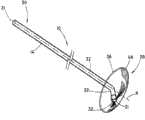
图1A是根据本发明的支架的立体图;Figure 1A is a perspective view of a stent according to the present invention;
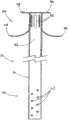
图1B是根据本发明的支架的替代实施方案的立体图;Figure 1B is a perspective view of an alternative embodiment of a stent according to the present invention;
图2是图1A所示的支架的替代性立体图;Figure 2 is an alternative perspective view of the stent shown in Figure 1A;
图3是根据本发明的实施方案的在本体中具有多个开口的支架的侧视图;Figure 3 is a side view of a bracket having multiple openings in the body according to an embodiment of the present invention;
图4是根据本发明的实施方案的围绕冠盖具有多个开口的支架的侧视图;Figure 4 is a side view of a brace having multiple openings around a crown according to an embodiment of the present invention;
图5A是根据本发明的显示了多个开口的支架的冠盖和本体的俯视立体图;5A is a top perspective view of the crown and body of a stent showing multiple openings in accordance with the present invention;
图5B是根据本发明的替代性实施方案的显示了多个开口的支架的冠盖和本体的侧视图;Figure 5B is a side view of the crown and body of a stent showing multiple openings according to an alternative embodiment of the present invention;
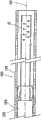
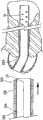
图6A是用于输送的其中具有图1A中的支架的导引器的侧剖图;Figure 6A is a side sectional view of the introducer with the stent in Figure 1A therein for delivery;
图6B是图6A所示的导引器的侧剖图,其中支架从导引器释放,并且冠盖扩张;Figure 6B is a side sectional view of the introducer shown in Figure 6A with the stent released from the introducer and the coronal expanded;
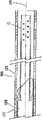
图7A是用于输送的其中具有图1B中的支架的导引器的侧剖图;7A is a side sectional view of the introducer with the stent in FIG. 1B therein for delivery;
图7B是图7A所示的导引器的侧剖图,其中支架从导引器释放,并且冠盖扩张,近侧部分处于成角度配置;Figure 7B is a side cross-sectional view of the introducer shown in Figure 7A, with the stent released from the introducer and the coronal expanded with the proximal portion in an angled configuration;
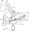
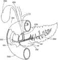
图8是经过胰管而前进的导线的示意图;Figure 8 is a schematic illustration of a lead advanced through the pancreatic duct;
图9是将预防支架设置在胰管之内的示意图;Fig. 9 is a schematic diagram of placing the prophylactic stent inside the pancreatic duct;
图10是处于胰管之内的支架的示意图,其中利用冠盖防止进入到胰管;并且Figure 10 is a schematic illustration of a stent within a pancreatic duct with a cap preventing access to the pancreatic duct; and
图11是进入胆管的导线的示意图。Figure 11 is a schematic illustration of a guidewire entering a bile duct.
具体实施方式Detailed ways
下面参考附图对本发明进行描述,在附图中,相同的元件以相同的附图标记来表示。通过下面的具体描述将更好地理解本发明的各个元件的关系和功能。然而,本发明的实施方案并不限于附图中所示的实施方案。应当理解,附图并非成比例的,并且在某些情况下已经省去了对于理解本发明并不必要的细节,例如常规的构造和组件。The invention is described below with reference to the accompanying drawings, in which like elements are denoted by like reference numerals. The relationship and function of the various elements of the invention will be better understood from the following detailed description. However, embodiments of the present invention are not limited to the embodiments shown in the drawings. It should be understood that the drawings are not to scale and in some instances details not necessary to an understanding of the invention have been omitted, such as conventional construction and components.
正如在说明书中所用到的,术语近侧和远侧应当就正在将支架输送到患者的内科医生进行理解。因此,术语“远侧”意指支架最远离内科医生的部分,并且术语“近侧”意指支架最接近内科医生的部分。As used in the specification, the terms proximal and distal should be understood with respect to a physician who is delivering a stent to a patient. Thus, the term "distal" means the part of the stent furthest from the physician and the term "proximal" means the part of the stent closest to the physician.
图1A、1B和2显示了根据本发明的支架10。支架10包括不能够扩张的基本管状本体14,管状本体14具有近侧部分20和远侧部分30。管状本体14沿着如图1A所示的轴线A在纵向上延伸。管腔32在近侧开口21和远侧开口31之间经过支架10的管状本体14的至少一部分延伸。近侧部分20包括冠盖部分36,并且配置用于将近侧设置到胰管,在下面将更具体地进行描述。在管状本体14上可以包括一个或一个以上保持构件38。如果存在保持构件,则其配置为有助于在胰管之内将支架10保持就位。在管状本体14中可以包括一个或一个以上开口42,如图3所示。开口42配置为便于经过支架10进行引流。Figures 1A, 1B and 2 show a
如图1A和1B所示,冠盖部分36从管状本体14向外基本在径向上延伸。冠盖部分36可以由曲线形成,并且其尺寸和形状设计为在支架10设置到胰管之内时覆盖胰管的开口。冠盖部分36可以是任何形状,例如如图1A和1B所示的圆形或者不会刺激胆管树(biliary tree)的任何形状。冠盖部分36的尺寸和形状还可以设计为使支架10不能完全进入胰管并陷入其中。冠盖部分36通常旨在保持在体腔中的胰管之外,并且在将支架10的管状本体14设置在胰管之内时保护管道的开口。冠盖部分36包括如图1A所示的近侧面37和如图1B所示的远侧面39。远侧面39配置为邻近管道的开口周围的组织。近侧面37配置为使长型医疗设备远离胰管偏转,并且还配置为禁止对比染料意外地进入到管道内。冠盖部分36可以为穹顶的,具有相对周边46升高的中心部分44。穹顶的中心部分44可以中心定位在冠盖部分36上或者可以是非对称的。穹顶的中心部分44可以按照圆锥或圆整形状渐缩,以帮助导线偏转进入胆管,如下文所述。在某些实施方案中,冠盖部分36在中心部分44中可以是基本平坦的,如图4所示。平坦的中心部分44还将配置为帮助导线偏转进入胆管而不是进入胰管。冠盖部分36的周边46向外延伸到冠盖部分36覆盖胰管开口的程度。周边46可以大于胰管处的开口,但是不应当过大,以致冠盖部分36干涉到进入胆总管。在某些实施方案中,冠盖部分36在近侧开口21中可以包括单向阀。该单向阀可以是本领域技术人员公知的任何种类的阀,一旦支架10设置就位,该阀将允许从胰管对胰液进行引流,并且将禁止对比染料进入胰管。按照非限制的实例,冠盖部分36的直径可以为大约3-5mm。对于冠盖部分36,其他尺寸的直径也是可以的。As shown in FIGS. 1A and 1B , the
近侧部分20可以包括成角度部分22,该成角度部分22远离图1B所示的纵向轴线A以一定角度延伸,从而使近侧开口21从轴线A偏移。当预防支架10在管道中设置就位时,具有成角度近侧部分22的这种配置还将有助于禁止长型医疗设备或对比染料进入到胰管内。如下文将要更具体地讨论的,支架10可以是为了输送而可变形的,从而使近侧成角度部分22可以与远侧部分30对准,进而可以越过导线输送支架10。支架10是可变形的,从而当支架10设置在胰腺的管道中时,支架10将恢复图1B所示的配置,其中成角度部分22远离轴线A形成角度,开口21从轴线A偏移。The
管状本体14和冠盖部分36配置为便于预防性地保护胰管,并便于将胰管引流到十二指肠。为了帮助便于对胰管进行引流,管状本体14和冠盖部分36可以包括一个或一个以上开口,即,如上所述的管状本体中的开口42。例如通过延伸到支架10的中心部分44中的开口52,管腔32可以经过本体14延伸到冠盖部分36。冠盖部分36可以包括多个开口52。例如,如图5A所示,冠盖部分36可以包括中心开口52,中心开口52由多个开口52环绕,所述多个开口52可操作地连接到管腔32,以便于从胰管中引流。如图5B所示,多个开口52可以被包括在冠盖部分36之上的管状本体14中,并且进一步包括盖子56,盖子56覆盖中心管腔32,以防止导线意外进入到支架10内,并且还允许经过支架10对胰管进行引流并引流到十二指肠内。在如图5B所示的实施方案中,冠盖部分36的尺寸和形状设计为覆盖并配合靠向胰管的开口,并且盖子56的尺寸和形状设计为保护管腔以及胰管的入口,还允许从支架10引流并允许进入到胆总管。盖子56可以具有比冠盖部分36的周边46更短的周边延伸部58。冠盖部分36和盖子56是柔韧的且可扩张的,从而使冠盖部分36可以收缩进入用于输送的折叠配置,并且当支架设置在胰管处时可以处于扩张配置。冠盖部分36也是柔韧的,从而使冠盖部分36与本体运动一起折曲,并使在植入位置处产生刺激的风险最小化。
在某些实施方案中,如上所述,一个或一个以上保持构件38可以从管状本体14向外延伸,以有助于在胰管之内将支架10保持就位。保持构件38可以是从管状本体14延伸长度为大约4-8mm的薄片。其它长度可以用于保持构件,并且可以取决于管道开口的尺寸、保持构件的柔韧性、支架的长度以及将支架10保持植入管道之内的时间量。保持构件38可以通过在管状构件14的壁中的纵向切口而由管状构件14形成。可替代地,保持构件可以通过与本体14一起模制或者附加到管状本体14或者本领域技术人员公知的任何方法而形成。保持构件38可以配置用于将支架10的远侧部分30保持在管道之内若干天或若干周,并随后使支架10自然地穿行到管道之外。In certain embodiments, one or
当设置两个或两个以上保持构件38时,保持构件38可以设置在支架10的圆周上或另外围绕支架10隔开。例如,第一保持构件38可以在与弯曲部分36的方向相对的大约180°的方向处向外径向延伸,如图1所示。第二保持构件38可以以与第一保持构件38成大约180°而径向向外延伸。保持构件38可以是足够柔韧的,以收缩靠向管状本体14,用于对支架10进行输送,并且保持构件38还具有足够的弹性,以接触胰管,从而支架10一旦设置于输送位置处就将支架10保持就位。When two or
支架10可以具有适合植入到胰管内的任何尺寸,并且将根据管道尺寸而改变。支架10可以具有大约3-10Fr的外径。支架10的内径可以为大约1-2mm。也可以使用更短或更长的支架。这些尺寸仅是示例性的,并且可以使用其他尺寸。可以制成支架的材料使得支架足够柔软,以顺从管道的曲率,并消除或减少在植入位置利用刚性支架而出现的刺激,由此降低胰腺炎、形态或管道改变的风险。这些材料还应当具有足够强度,以便在支架定位于管道之内时维持经过支架的管腔。在某些实施方案中,支架10或其一部分可以由生物可降解材料制成。用于支架10的示例性材料包括但不限于下列材料:SOFFLEXTM、一种聚醚尿烷、硅酮、嵌段共聚物、尿烷、聚乙烯、聚苯乙烯、聚四氟乙烯(PTFE)、FEP等及其组合。在某些实施方案中,支架10可以由生物可降解材料形成。大量生物可吸收均聚物、共聚物或者生物可吸收聚合物的混合物在医疗技术中是公知的。这些材料包括但并不限于:包括聚-α羟基和聚-β羟基聚酯、聚己酸内酯、聚乙醇酸、聚醚酯、聚(对-二氧六环酮)、聚氧杂酯的聚酯;聚磷腈;聚酐;包括聚三亚甲基碳酸酯、聚(亚氨碳酸酯)的聚碳酸酯;聚酰胺酯;聚氨酯;多异氰酸酯;聚磷腈;包括聚乙二醇聚原酸酯的聚醚;包括聚环氧乙烷的环氧聚合物;包括纤维素、壳多糖、葡聚糖、淀粉、羟乙基淀粉、聚葡糖酸酯、透明质酸的多糖;包括聚氨基酸、聚酯-酰胺、聚谷氨酸、聚-赖氨酸、明胶、纤维蛋白、纤维蛋白原、酪蛋白、胶原蛋白的聚酰胺。可以修改为与冠盖部分一起使用的示例性的不能够扩张的管状支架包括但不限于ST-2SOEHENDRA TANNENBAUM


冠盖部分36可以由与本体14相同或不同的材料形成。例如,冠盖部分36可以由聚氨酯形成,而管状本体14由聚乙烯形成。可替换地,支架10可以由单一结构形成,即,整个支架由硅酮或聚氨酯形成。在某些实施方案中,冠盖部分36可以包括柔韧性材料范围内的金属线。所述线可以由本领域技术人员公知的任何金属形成,其与植入物相容并且足够柔韧,以允许冠盖部分36在扩张配置和非扩张配置之间活动。冠盖部分36可以利用本领域技术人员公知的任何方法(例如粘结、焊接等)连接到管状本体14。当各部分由同样的材料形成时,冠盖部分36还可以与管状本体14整体形成。冠盖36还可以包括涂层,以便于医疗设备远离支架10的近侧开口21偏转。例如,冠盖部分36可以包括涂层,以提高润滑性。可替代地,冠盖部分36可以由润滑性提高的材料形成。按照非限制的实例,润滑材料可以选自如下材料:从选自环氧乙烷的单体产生的聚合物;2-乙烯基吡啶;N-乙烯吡咯烷酮;聚乙二醇丙烯酸酯,例如单-烷氧基聚乙烯乙二醇单(甲基)丙烯酸脂,包括单-甲氧基三乙二醇单(甲基)丙烯酸脂、单-甲氧基四乙二醇单(甲基)丙烯酸脂、聚乙二醇单(甲基)丙烯酸脂;其他亲水性丙烯酸脂,例如甲基丙烯酸2-羟基乙酯、甲基丙烯酸甘油酯;丙烯酸及其盐;丙烯酰胺和丙烯腈;丙烯酰胺甲基丙磺酸及其盐,纤维素,纤维素衍生物,例如甲基纤维素乙基纤维素、羧甲基纤维素、氰乙基纤维素、纤维素乙酸酯,多糖,例如直链淀粉、果胶、支链淀粉、褐藻酸以及交联肝磷脂。The
在某些实施方案中,支架10可以包括不透射线的标记(未显示),以帮助支架10在管道中定位。在某些实施方案中,支架10本身可以是不透射线的。某些实施方案可以包括由可视化的激光或墨水产生的可视标记,因此支架10可以通过荧光透视法或X射线而可视化。本领域技术人员公知的任何类型的可视化标记都可以与支架10一起使用。In certain embodiments, the
当内科医生利用导线实际上以胆管为预期目的而意外地进入胰管时,支架10可以被输送到胰管。如上所述,利用导线和导管在胆管树之内行进是困难的。为了避免在程序过程中另外意外地进入胰管,并且减小由于意外进入或反复进入胰管所引起的胰腺炎的风险,可以使导线留在胰管之内的位置,并且可以将本发明的支架10越过导线传送到胰管。可以将支架10设置在胰管之内,使得冠盖部分36防止在利用导线另外进入管道的情况下进一步刺激胰管,或者防止对比染料意外注入到胰管内。冠盖部分36定位为保护胰管,并且使导线向着胆管偏转。在导线意外进入支架10的管腔32的情况下,管状本体14对管道进行保护,并且可以将导线撤走并重新进行定向,而不会刺激胰管。The
可以利用本领域公知的任何输送系统越过意外进入胰管的导线将支架10输送到植入位置。所使用的输送系统将取决于支架10的尺寸和用于形成支架10的材料。输送系统100包括已经进入胰管的导线110以及可以越过导线110前进的导引器导管120。支架10定位在导引器导管120之内,如图6A所示。导引器导管120可以包括推动导管126和外鞘128,用于输送具有处于非扩张配置的冠盖部分的支架10,从而使导管行进到位。在输送到位的过程中,支架10设置为越过导线110,并且支架10的冠盖部分36处于非扩张配置。一旦导引器导管120已经从处于输送位置的支架10移走,冠盖部分36就呈现图6B所示的扩张配置,以覆盖胰管200的开口。本领域技术人员将理解,导线110和导引器导管120具有足够长度,以从患者身体中的预期位置延伸到患者体外。输送系统100还可以包括附加管腔。The
具有成角度近侧部分22和从轴线A偏移的近侧开口21的图1B所示的支架10也可以利用本领域公知的输送系统进行输送,例如图6A和6B所示的输送系统100。图7A和7B中显示了支架10的定位,其中管腔32沿着导线110在导引器导管120之内延伸。图7B显示的成角度近侧部分22在从支架10移走导线110和导引器导管120之后恢复到成角度配置。The
下面将参考输送系统100阐述本发明的支架10的输送和植入的示例性方法。如图8-11所示,输送系统100可以用于在胰腺210的胰管200中设置支架10。如图8所示,导线110已经从内窥镜212经过法特氏壶腹214意外地前进到胰管200而不是胆总管220之内。在从胰管200撤走导线110并试图进入胆管之前,可以将支架10定位在胰管200之内,以预防性地保护管道200免受进一步刺激和损伤。导线110留在管道200中,并且支架10越过导线110前进,并通过导引器导管120前进到内窥镜212之外。作为参照,也显示了十二指肠222、胆囊管224和胆囊226。导引器导管120通过沿着导线110向远侧推动支架10直到抵达胰管200,从而使支架10越过导线110前进到位。支架10可以前进直到管状本体14定位于管道200之内。冠盖部分36从导管120释放,并且呈现扩张配置,以覆盖管道200的开口,如图9所示。冠盖部分36定位于管道200之外,并且覆盖管道200的开口。从管道200撤走导线110,并将支架10留在如图10所示的位置,以预防性地保护胰管200免受导线110的进一步刺激和避免其进入,或者保护胰管200免受对比染料的意外注入。图11显示的导线110经过法特氏壶腹214前进,并从支架10的冠盖部分36偏转,并且进入胆管220。An exemplary method of delivery and implantation of the
可以将支架10保留在位达大约两周。也可以使支架10的植入周期更短或更长。可以通过自然的身体功能将支架10推送到管道200之外,或者可以通过外科手术将支架10移走。在支架10或其各部分为生物可降解的情况下,支架10将降解并由身体排出。在某些实施方案中,管状本体14可以是可降解的,并且冠盖部分36可以不是可降解的。在此情况下,管状本体14可以降解,从而使冠盖部分36下降进入到十二指肠222并通过身体排出。
上文中的附图和公开旨在描述而非穷举。这些描述对于本领域技术人员来说将暗示许多变型和替换方式。所有这些变型和替换方式旨在包含于所附权利要求书的范围之内。熟悉本领域的技术人员会认识到与本文所描述的具体实施方案等同的其他技术方案,这些等同技术方案也旨在由所附权利要求书所包含。例如,在胆管系统的背景下已经描述的本发明只是出于显示目的。按照非限制的实例,本领域技术人员可以将本发明的原理应用到患者身体之内的任何其他分支的管腔或脉管(包括例如胰腺系统的消化道之内的区域以及例如其他血管系统的消化道之外的区域),并且其旨在包含于所附权利要求书的范围之内。The figures and disclosures above are intended to be descriptive and not exhaustive. These descriptions will suggest many variations and alternatives to those skilled in the art. All such modifications and alternatives are intended to be included within the scope of the appended claims. Those skilled in the art will recognize other equivalents to the specific embodiments described herein and such equivalents are also intended to be encompassed by the appended claims. For example, the invention has been described in the context of the biliary system for illustration purposes only. By way of non-limiting example, those skilled in the art may apply the principles of the present invention to any other branching lumen or vessel within a patient's body (including, for example, areas within the alimentary canal of the pancreatic system and areas such as other vascular systems). areas outside the digestive tract) and are intended to be within the scope of the appended claims.
Claims (20)
Applications Claiming Priority (3)
| Application Number | Priority Date | Filing Date | Title |
|---|---|---|---|
| US10750208P | 2008-10-22 | 2008-10-22 | |
| US61/107,502 | 2008-10-22 | ||
| PCT/US2009/061217WO2010048106A2 (en) | 2008-10-22 | 2009-10-20 | Prophylactic pancreatic stent |
Publications (1)
| Publication Number | Publication Date |
|---|---|
| CN102202605Atrue CN102202605A (en) | 2011-09-28 |
Family
ID=42078046
Family Applications (1)
| Application Number | Title | Priority Date | Filing Date |
|---|---|---|---|
| CN200980142221XAPendingCN102202605A (en) | 2008-10-22 | 2009-10-20 | Prophylactic pancreatic stent |
Country Status (3)
| Country | Link |
|---|---|
| US (1) | US20100114325A1 (en) |
| CN (1) | CN102202605A (en) |
| WO (1) | WO2010048106A2 (en) |
Cited By (2)
| Publication number | Priority date | Publication date | Assignee | Title |
|---|---|---|---|---|
| CN104507422A (en)* | 2013-03-07 | 2015-04-08 | 奥林巴斯医疗株式会社 | Medical stent |
| CN111346267A (en)* | 2020-04-14 | 2020-06-30 | 中国人民解放军海军军医大学第三附属医院 | Area can absorb antibiotic pancreas pipe drainage tube of hemostasis |
Families Citing this family (24)
| Publication number | Priority date | Publication date | Assignee | Title |
|---|---|---|---|---|
| US20100106255A1 (en)* | 2008-10-24 | 2010-04-29 | Dubin Marc G | Self-expanding frontal sinus stent and insertion tool |
| US8603185B2 (en)* | 2010-03-11 | 2013-12-10 | Cook Medical Technologies Llc | Stent geometry |
| EP2665433B1 (en)* | 2011-01-19 | 2021-03-10 | Fractyl Laboratories Inc. | Devices for the treatment of tissue |
| CA2865567C (en) | 2012-02-27 | 2022-10-11 | Fractyl Laboratories, Inc. | Heat ablation systems, devices and methods for the treatment of tissue |
| EP3711810B1 (en) | 2012-04-19 | 2023-02-22 | Fractyl Health, Inc. | Tissue expansion systems |
| WO2014014748A1 (en)* | 2012-07-20 | 2014-01-23 | Cook Medical Technologies Llc | Anti -migration biliary stent |
| EP3714826A1 (en) | 2012-07-30 | 2020-09-30 | Fractyl Laboratories, Inc. | Electrical energy ablation systems and devices for the treatment of tissue |
| WO2014026055A1 (en) | 2012-08-09 | 2014-02-13 | Fractyl Laboratories Inc. | Ablation systems, devices and methods for the treatment of tissue |
| EP2903626A4 (en) | 2012-10-05 | 2016-10-19 | Fractyl Lab Inc | METHODS, SYSTEMS AND DEVICES FOR REALIZING MULTIPLE TREATMENTS ON A PATIENT |
| EP3003461B1 (en) | 2013-06-04 | 2019-05-01 | Fractyl Laboratories, Inc. | Systems and devices for reducing the luminal surface area of the gastrointestinal tract |
| EP3020376A4 (en)* | 2013-07-11 | 2017-01-11 | Olympus Corporation | Stent |
| NL2011186C2 (en)* | 2013-07-17 | 2015-01-21 | Overtoom Ltd | A catheter system for delivery of a ureteral catheter, use of such catheter system, and method. |
| EP3043732B1 (en) | 2013-09-12 | 2021-04-07 | Fractyl Laboratories, Inc. | Systems and devices for treatment of target tissue |
| KR102284469B1 (en) | 2013-11-22 | 2021-08-02 | 프랙틸 헬쓰, 인코포레이티드 | Systems, devices and methods for the creation of a therapeutic restriction in the gastrointestinal tract |
| US10959774B2 (en) | 2014-03-24 | 2021-03-30 | Fractyl Laboratories, Inc. | Injectate delivery devices, systems and methods |
| US9757535B2 (en) | 2014-07-16 | 2017-09-12 | Fractyl Laboratories, Inc. | Systems, devices and methods for performing medical procedures in the intestine |
| EP3169260B1 (en) | 2014-07-16 | 2019-09-25 | Fractyl Laboratories, Inc. | System for treating diabetes and related diseases and disorders |
| US11185367B2 (en) | 2014-07-16 | 2021-11-30 | Fractyl Health, Inc. | Methods and systems for treating diabetes and related diseases and disorders |
| US9839508B2 (en)* | 2014-10-09 | 2017-12-12 | Boston Scientific Scimed, Inc. | Pancreatic stent with drainage feature |
| JP5981081B1 (en)* | 2014-10-28 | 2016-08-31 | オリンパス株式会社 | Ultrasonic endoscope, ultrasonic endoscope suction device, and ultrasonic endoscope system |
| JP7495778B2 (en) | 2015-10-07 | 2024-06-05 | メイヨ・ファウンデーション・フォー・メディカル・エデュケーション・アンド・リサーチ | Electroporation for the treatment of obesity or diabetes |
| RU2665622C1 (en)* | 2017-04-27 | 2018-09-03 | Дмитрий Равильевич Зинатулин | Method for removing a non-functioning plastic biliary stent from the bile ducts |
| EP4048179A1 (en) | 2019-10-21 | 2022-08-31 | Endogenex, Inc. | Devices, systems, and methods for pulsed electric field treatment of the duodenum |
| EP4090282A4 (en) | 2020-01-15 | 2024-02-21 | Fractyl Health, Inc. | AUTOMATIC FABRIC TREATMENT DEVICES, SYSTEMS AND METHODS |
Citations (3)
| Publication number | Priority date | Publication date | Assignee | Title |
|---|---|---|---|---|
| US20050240280A1 (en)* | 2004-04-26 | 2005-10-27 | Peter Aliski | Ureteral stent |
| US20050240141A1 (en)* | 2004-04-26 | 2005-10-27 | Peter Aliski | Stent kidney curl improvements |
| CN1927421A (en)* | 2006-09-21 | 2007-03-14 | 中国人民解放军第二军医大学 | Pipe support capable of load-bearing minisize active particle source |
Family Cites Families (3)
| Publication number | Priority date | Publication date | Assignee | Title |
|---|---|---|---|---|
| US7455688B2 (en)* | 2004-11-12 | 2008-11-25 | Con Interventional Systems, Inc. | Ostial stent |
| JP2010502298A (en)* | 2006-08-28 | 2010-01-28 | ウィルソン−クック・メディカル・インコーポレーテッド | Stent with antibacterial drainage lumen surface |
| WO2008148385A1 (en)* | 2007-06-06 | 2008-12-11 | Pnn Medical A/S | A stent |
- 2009
- 2009-10-20CNCN200980142221XApatent/CN102202605A/enactivePending
- 2009-10-20USUS12/582,036patent/US20100114325A1/ennot_activeAbandoned
- 2009-10-20WOPCT/US2009/061217patent/WO2010048106A2/enactiveApplication Filing
Patent Citations (3)
| Publication number | Priority date | Publication date | Assignee | Title |
|---|---|---|---|---|
| US20050240280A1 (en)* | 2004-04-26 | 2005-10-27 | Peter Aliski | Ureteral stent |
| US20050240141A1 (en)* | 2004-04-26 | 2005-10-27 | Peter Aliski | Stent kidney curl improvements |
| CN1927421A (en)* | 2006-09-21 | 2007-03-14 | 中国人民解放军第二军医大学 | Pipe support capable of load-bearing minisize active particle source |
Cited By (2)
| Publication number | Priority date | Publication date | Assignee | Title |
|---|---|---|---|---|
| CN104507422A (en)* | 2013-03-07 | 2015-04-08 | 奥林巴斯医疗株式会社 | Medical stent |
| CN111346267A (en)* | 2020-04-14 | 2020-06-30 | 中国人民解放军海军军医大学第三附属医院 | Area can absorb antibiotic pancreas pipe drainage tube of hemostasis |
Also Published As
| Publication number | Publication date |
|---|---|
| US20100114325A1 (en) | 2010-05-06 |
| WO2010048106A2 (en) | 2010-04-29 |
| WO2010048106A3 (en) | 2010-06-17 |
Similar Documents
| Publication | Publication Date | Title |
|---|---|---|
| CN102202605A (en) | Prophylactic pancreatic stent | |
| US12251298B2 (en) | Incising implant for the prostatic urethra | |
| CN102791316B (en) | Bracket Geometry | |
| JP5764577B2 (en) | Endoscope sheath | |
| ES2368589T3 (en) | CATHETER FOR THE IMPLEMENTATION OF ENDOPROOTHESIS. | |
| ES2424656T3 (en) | Vascular stent delivery system with ramifications | |
| EP1420720B1 (en) | Stent and applicator | |
| US7967770B2 (en) | Implantable drainage device with planar dual curved portion | |
| JP5226515B2 (en) | Access kit | |
| EP2067499B1 (en) | Expandable guide sheath and apparatus and methods using such sheaths | |
| EP1951167B1 (en) | Introducer for implantable device | |
| EP2227153B1 (en) | Two-part extraction balloon | |
| US20140277561A1 (en) | Pancreatic stent drainage system | |
| ES2938875T3 (en) | thrombectomy device | |
| US20100317963A1 (en) | Endoscopic ultrasound-guided stent placement device and method | |
| JP2009543660A (en) | Nipple dilator | |
| US20140121583A1 (en) | Bartholin Gland Drainage Catheter and Methods of Using the Same | |
| EP2874567B1 (en) | Anti-migration biliary stent | |
| CN116456941A (en) | Stent device and method for increasing patency of body opening | |
| ES1295705U (en) | INTRODUCER DEVICE FOR STENT GRAFT (Machine-translation by Google Translate, not legally binding) | |
| PL238024B1 (en) | System delivering implants used in structural heart diseases by a minimally invasive method |
Legal Events
| Date | Code | Title | Description |
|---|---|---|---|
| C06 | Publication | ||
| PB01 | Publication | ||
| C10 | Entry into substantive examination | ||
| SE01 | Entry into force of request for substantive examination | ||
| C02 | Deemed withdrawal of patent application after publication (patent law 2001) | ||
| WD01 | Invention patent application deemed withdrawn after publication | Application publication date:20110928 |