CN102202584A - Surgical stapling instrument for applying large staples through small delivery holes and method for securing tissue folds with surgical stapler - Google Patents
Surgical stapling instrument for applying large staples through small delivery holes and method for securing tissue folds with surgical staplerDownload PDFInfo
- Publication number
- CN102202584A CN102202584ACN200980119073.XACN200980119073ACN102202584ACN 102202584 ACN102202584 ACN 102202584ACN 200980119073 ACN200980119073 ACN 200980119073ACN 102202584 ACN102202584 ACN 102202584A
- Authority
- CN
- China
- Prior art keywords
- staples
- staple
- shaft
- seam
- surgical stapling
- Prior art date
- Legal status (The legal status is an assumption and is not a legal conclusion. Google has not performed a legal analysis and makes no representation as to the accuracy of the status listed.)
- Pending
Links
Images


Classifications
- A—HUMAN NECESSITIES
- A61—MEDICAL OR VETERINARY SCIENCE; HYGIENE
- A61B—DIAGNOSIS; SURGERY; IDENTIFICATION
- A61B17/00—Surgical instruments, devices or methods
- A61B17/068—Surgical staplers, e.g. containing multiple staples or clamps
- A—HUMAN NECESSITIES
- A61—MEDICAL OR VETERINARY SCIENCE; HYGIENE
- A61B—DIAGNOSIS; SURGERY; IDENTIFICATION
- A61B17/00—Surgical instruments, devices or methods
- A61B17/064—Surgical staples, i.e. penetrating the tissue
- A61B17/0644—Surgical staples, i.e. penetrating the tissue penetrating the tissue, deformable to closed position
- A—HUMAN NECESSITIES
- A61—MEDICAL OR VETERINARY SCIENCE; HYGIENE
- A61B—DIAGNOSIS; SURGERY; IDENTIFICATION
- A61B17/00—Surgical instruments, devices or methods
- A61B17/00234—Surgical instruments, devices or methods for minimally invasive surgery
- A—HUMAN NECESSITIES
- A61—MEDICAL OR VETERINARY SCIENCE; HYGIENE
- A61B—DIAGNOSIS; SURGERY; IDENTIFICATION
- A61B17/00—Surgical instruments, devices or methods
- A61B17/068—Surgical staplers, e.g. containing multiple staples or clamps
- A61B17/0682—Surgical staplers, e.g. containing multiple staples or clamps for applying U-shaped staples or clamps, e.g. without a forming anvil
- A61B17/0684—Surgical staplers, e.g. containing multiple staples or clamps for applying U-shaped staples or clamps, e.g. without a forming anvil having a forming anvil staying above the tissue during stapling
- A—HUMAN NECESSITIES
- A61—MEDICAL OR VETERINARY SCIENCE; HYGIENE
- A61B—DIAGNOSIS; SURGERY; IDENTIFICATION
- A61B17/00—Surgical instruments, devices or methods
- A61B17/56—Surgical instruments or methods for treatment of bones or joints; Devices specially adapted therefor
- A61B17/58—Surgical instruments or methods for treatment of bones or joints; Devices specially adapted therefor for osteosynthesis, e.g. bone plates, screws or setting implements
- A61B17/60—Surgical instruments or methods for treatment of bones or joints; Devices specially adapted therefor for osteosynthesis, e.g. bone plates, screws or setting implements for external osteosynthesis, e.g. distractors, contractors
- A61B17/64—Devices extending alongside the bones to be positioned
- A61B17/6425—Devices extending alongside the bones to be positioned specially adapted to be fitted across a bone joint
- A—HUMAN NECESSITIES
- A61—MEDICAL OR VETERINARY SCIENCE; HYGIENE
- A61B—DIAGNOSIS; SURGERY; IDENTIFICATION
- A61B17/00—Surgical instruments, devices or methods
- A61B17/00234—Surgical instruments, devices or methods for minimally invasive surgery
- A61B2017/00292—Surgical instruments, devices or methods for minimally invasive surgery mounted on or guided by flexible, e.g. catheter-like, means
- A61B2017/0034—Surgical instruments, devices or methods for minimally invasive surgery mounted on or guided by flexible, e.g. catheter-like, means adapted to be inserted through a working channel of an endoscope
- A—HUMAN NECESSITIES
- A61—MEDICAL OR VETERINARY SCIENCE; HYGIENE
- A61B—DIAGNOSIS; SURGERY; IDENTIFICATION
- A61B17/00—Surgical instruments, devices or methods
- A61B2017/00743—Type of operation; Specification of treatment sites
- A61B2017/00818—Treatment of the gastro-intestinal system
- A—HUMAN NECESSITIES
- A61—MEDICAL OR VETERINARY SCIENCE; HYGIENE
- A61B—DIAGNOSIS; SURGERY; IDENTIFICATION
- A61B17/00—Surgical instruments, devices or methods
- A61B17/064—Surgical staples, i.e. penetrating the tissue
- A61B2017/0649—Coils or spirals
- A—HUMAN NECESSITIES
- A61—MEDICAL OR VETERINARY SCIENCE; HYGIENE
- A61B—DIAGNOSIS; SURGERY; IDENTIFICATION
- A61B17/00—Surgical instruments, devices or methods
- A61B17/28—Surgical forceps
- A61B17/29—Forceps for use in minimally invasive surgery
- A61B2017/2926—Details of heads or jaws
- A61B2017/2927—Details of heads or jaws the angular position of the head being adjustable with respect to the shaft
- A61B2017/2929—Details of heads or jaws the angular position of the head being adjustable with respect to the shaft with a head rotatable about the longitudinal axis of the shaft
Landscapes
- Health & Medical Sciences (AREA)
- Life Sciences & Earth Sciences (AREA)
- Surgery (AREA)
- Heart & Thoracic Surgery (AREA)
- Engineering & Computer Science (AREA)
- Biomedical Technology (AREA)
- Nuclear Medicine, Radiotherapy & Molecular Imaging (AREA)
- Medical Informatics (AREA)
- Molecular Biology (AREA)
- Animal Behavior & Ethology (AREA)
- General Health & Medical Sciences (AREA)
- Public Health (AREA)
- Veterinary Medicine (AREA)
- Surgical Instruments (AREA)
Abstract
Description
Translated fromChinese技术领域technical field
本发明整体涉及体腔内的组织对合。更具体地讲,本发明涉及薄型外科缝合器,用于将大缝钉通过小套管针孔或柔性内窥镜递送至体腔。本发明还涉及减肥手术过程中使用薄型外科缝合器将组织在体腔内固定到一起的方法。The present invention generally relates to tissue apposition in body cavities. More particularly, the present invention relates to low profile surgical staplers for delivering large staples through small trocar holes or flexible endoscopes to body cavities. The invention also relates to a method of using a low profile surgical stapler to secure tissue together in a body cavity during bariatric surgery.
背景技术Background technique
肥胖症是美国30%以上人口患有的疾病。肥胖症影响个人的生活质量,并且显著提高了发病率和死亡率。肥胖症患者(即体重指数(BMI)大于30的个体)通常有遭遇包括早逝在内的健康问题(如糖尿病、高血压和呼吸功能不全)的高风险。据此可知,且本领域的技术人员肯定了解,肥胖症涉及大量的金钱支出和体力消耗。事实上,据估计与肥胖症有关的花费仅在美国就超过1000亿美元。研究表明,对于许多患者来说,单纯通过饮食和运动进行的保守治疗可能无法有效减去多余的体重。肥胖症治疗学是涉及控制和治疗肥胖症的医学分支学科。肥胖症治疗学领域已研究出用于治疗肥胖症的多种外科手术。目前最常进行的手术是Roux-en-Y胃旁路术(RYGB)。该手术非常复杂,通常用来治疗表现出病态肥胖的患者。在RYGB手术中,将小胃囊与胃脘的其余部分分离,然后附接到小肠的切除部分。此小肠的切除部分在“较小”胃脘与小肠的远侧段之间连接,让食物在两者之间通过。常规的RYGB手术需要很长的手术时间。由于其侵入程度大,术后康复可能会漫长而痛苦。仅在美国每年就进行远不止100,000例的RYGB手术,耗费大量的保健开支。Obesity is a disease that affects more than 30% of the U.S. population. Obesity affects an individual's quality of life and significantly increases morbidity and mortality. Obese patients (ie, individuals with a body mass index (BMI) greater than 30) are often at high risk for health problems, including early death, such as diabetes, hypertension, and respiratory insufficiency. From this it is known, and those skilled in the art certainly understand, that obesity involves substantial monetary expenditure and physical exertion. In fact, obesity-related costs are estimated to exceed $100 billion in the United States alone. Research shows that, for many patients, conservative treatment with diet and exercise alone may not be effective in losing excess weight. Bariatrics is the branch of medicine concerned with the management and treatment of obesity. The field of obesity therapeutics has developed a variety of surgical procedures for the treatment of obesity. The most commonly performed procedure today is Roux-en-Y gastric bypass (RYGB). The procedure is complex and is often performed on patients who appear to be morbidly obese. In RYGB surgery, the small gastric pouch is separated from the rest of the gastric cavity and then attached to the resected portion of the small intestine. This resected portion of the small intestine connects between the "lesser" gastric cavity and the distal segment of the small intestine, allowing food to pass between the two. Conventional RYGB surgery requires a long operating time. Due to its degree of invasiveness, postoperative recovery can be long and painful. Well over 100,000 RYGB procedures are performed each year in the United States alone, costing substantial healthcare expenditures.
鉴于RYGB手术的高侵入性,已研发了其他侵入性较小的手术。这些手术包括将胃收紧而形成沙漏状的胃束带手术。该手术限制了从胃的一部分进入下一部分的食物量,从而诱发饱腹感。束带设置在靠近胃部和食道连接处的胃部周围。小的上部胃囊被快速填充,并且通过狭窄出口缓慢排空,以致产生饱腹感。已研究出的治疗肥胖病的其他形式包括Fobi袋胃绕道、胆胰分流术和胃成形术或“胃间隔手术”。Given the highly invasive nature of RYGB surgery, other less invasive procedures have been developed. These procedures include gastric banding, which tightens the stomach into an hourglass shape. The procedure limits the amount of food that passes from one part of the stomach to the next, thereby inducing a feeling of fullness. A band is placed around the stomach near the junction of the stomach and the esophagus. The small upper gastric pouch fills rapidly and empties slowly through the narrow opening, resulting in a feeling of fullness. Other forms of treatment for obesity that have been investigated include Fobi pouch gastric bypass, biliopancreatic diversion, and gastroplasty or "gastric septum surgery".
病态肥胖病被定义为超过个人理想体重100磅以上。对于这类人,由于面临严重的健康问题和致死风险,推荐治疗方式可以为RYGB、胃束带术或另一种更复杂的手术。然而,在美国和其他地方有越来越多的人超重而未被视为病态肥胖。这些人可能超重20-30磅并想减轻体重,但一直未能仅通过节食和锻炼而成功。对于这些个体而言,与RYGB或其他复杂手术相关的风险之弊往往压倒计入成本后可能的健康效益之利。因此,治疗选择方案应包括具有侵入较少、成本较低的减肥手段。Morbid obesity is defined as being more than 100 pounds over an individual's ideal body weight. For such people, because of the serious health problems and risk of death, the recommended treatment could be RYGB, gastric banding, or another more complicated procedure. However, a growing number of people in the United States and elsewhere are overweight without being considered morbidly obese. These are people who may be 20-30 pounds overweight and want to lose weight, but have been unsuccessful with diet and exercise alone. For these individuals, the risks and harms associated with RYGB or other complex procedures often outweigh the possible health benefits when factored in the cost. Therefore, treatment options should include less invasive, less costly weight loss options.
基于上述考虑,希望外科减肥手术(及相关的医疗器械)成本不高,几乎没有潜在并发症,并且在为患者提供减肥有益效果的同时为保持减肥效果所必需的生活方式改变赢取时间。此外,考虑到快速恢复且较少结疤,期望手术和医疗器械对患者的侵入最小。本发明提供了一种医疗器械,以能够通过快捷有效的方式进行外科减肥手术。Based on the above considerations, it is desirable that surgical bariatric surgery (and associated medical devices) be inexpensive, have few potential complications, and provide patients with weight loss benefits while buying time for the lifestyle changes necessary to maintain weight loss. Furthermore, it is desirable for the surgery and medical devices to be minimally invasive to the patient in view of rapid recovery and less scarring. The present invention provides a medical device for performing bariatric surgery in a quick and effective manner.
发明内容Contents of the invention
因此,本发明的目的是提供允许将大尺寸缝钉经小的开口或孔递送至体腔内的薄型外科缝合器。外科缝合器包括柄部,柄部具有可活动地连接到其上的扳机。外科缝合器还包括从柄部向远侧延伸的细长管轴。管轴包括固定于柄部的近端和在其中形成布署口的远端。缝钉布署组件设置在管轴的内部,用于从轴远端处的布署口发射缝钉,缝钉布署组件支撑缝钉,使得缝钉纵轴与管轴纵轴对齐。布署口的形状和尺寸设定成允许将缝钉从轴内离开布署口布署到相邻组织内。Accordingly, it is an object of the present invention to provide a low profile surgical stapler that allows delivery of large size staples through small openings or holes into body lumens. A surgical stapler includes a handle having a trigger movably connected thereto. The surgical stapler also includes an elongated tubular shaft extending distally from the handle. The shaft includes a proximal end secured to the handle and a distal end defining a deployment port therein. A staple deployment assembly is disposed inside the tubular shaft for firing staples from the deployment port at the distal end of the shaft, the staple deployment assembly supports the staples such that the longitudinal axis of the staples is aligned with the longitudinal axis of the tubular shaft. The deployment port is shaped and sized to allow the deployment of staples from within the shaft out of the deployment port into adjacent tissue.
本发明的另一个目的是提供这样的外科缝合器,其中所述轴具有小于约5mm的直径。Another object of the present invention is to provide such a surgical stapler wherein the shaft has a diameter of less than about 5mm.
本发明的又一个目的是提供这样的外科缝合器,其中所述轴可旋转地固定到柄部。Yet another object of the present invention is to provide such a surgical stapler wherein the shaft is rotatably secured to the handle.
本发明的再一个目的是提供这样的外科缝合器,其中所述轴的旋转与缝钉布署组件的旋转相配合。It is yet another object of the present invention to provide such a surgical stapler wherein rotation of the shaft is coordinated with rotation of the staple deploying assembly.
本发明的还有一个目的是提供这样的外科缝合器,其中缝钉布署组件包括沿纵向延伸经过轴的第一缝钉驱动器和第二缝钉驱动器。It is yet another object of the present invention to provide such a surgical stapler wherein the staple deploying assembly includes a first staple driver and a second staple driver extending longitudinally across the shaft.
本发明再有一个目的是提供这样的外科缝合器,其中第一缝钉驱动器包括成形为作用于缝钉的凸轮表面,第二缝钉驱动器包括成形为作用于缝钉的凸轮表面。It is yet another object of the present invention to provide such a surgical stapler wherein the first staple driver includes a camming surface shaped to engage the staples and the second staple driver includes a camming surface shaped to engage the staples.
本发明再有一个目的是提供这样的外科缝合器,其中第一弯曲臂和第二弯曲臂纵向设置在轴内,并且取向为面向布署口,使得缝钉在折叠过程中能够支撑在其上,然后从布署口射出。Yet another object of the present invention is to provide such a surgical stapler wherein the first and second curved arms are disposed longitudinally within the shaft and are oriented to face the deployment port so that the staples can be supported thereon during folding , then fires from the deployment port.
本发明再有一个目的是提供这样的外科缝合器,其中第一缝钉驱动器包括成形为作用于第一弯曲臂的凸轮表面,第二缝钉驱动器包括成形为作用于第二弯曲臂的凸轮表面。Yet another object of the present invention is to provide such a surgical stapler wherein the first staple driver includes a cam surface shaped to act on the first curved arm and the second staple driver includes a cam surface shaped to act on the second curved arm .
本发明再有一个目的是提供这样的外科缝合器,其中缝钉包括具有纵轴线的长主体段,第一叉尖和第二叉尖位于主体段的相对端并且在与主体段纵轴线基本上垂直的方向上延伸。Yet another object of the present invention is to provide such a surgical stapler, wherein the staples include an elongated body section having a longitudinal axis, a first prong and a second prong positioned at opposite ends of the body section and substantially at the same distance from the body section longitudinal axis extend vertically.
本发明再有一个目的是提供这样的外科缝合器,其中主体段包括在缝钉中心处的框。Yet another object of the present invention is to provide such a surgical stapler wherein the main body section includes a frame at the center of the staple.
本发明再有一个目的是提供这样的外科缝合器,其中缝钉布署组件包括其形状和尺寸设定成在框处支撑缝钉的柱。Yet another object of the present invention is to provide such a surgical stapler wherein the staple deploying assembly includes a post shaped and dimensioned to support the staples at the frame.
本发明再有一个目的是提供具有锁杆的外科缝合器,所述锁杆选择性地在支柱和缝钉上滑动,以在缝钉击发前将其锁定就位。Yet another object of the present invention is to provide a surgical stapler having a locking bar that selectively slides over posts and staples to lock the staples in place prior to firing them.
本发明再有一个目的是提供这样的外科缝合器,其中布署口位于轴的远侧末端。Yet another object of the present invention is to provide such a surgical stapler wherein the deployment port is located at the distal end of the shaft.
本发明再有一个目的是提供这样的外科缝合器,其中缝钉布署组件包括具有中心支架的砧块,中心支架与缝钉接合,以在经轴传送过程中夹持缝钉。It is yet another object of the present invention to provide such a surgical stapler wherein the staple deploying assembly includes an anvil having a central support that engages the staples to retain the staples during beam delivery.
本发明再有一个目的是提供这样的外科缝合器,其中砧块包括第一弯曲导引件和第二弯曲导引件,第一弯曲导引件和第二弯曲导引件形成一种在布署过程中缝钉围绕其成形的结构。Yet another object of the present invention is to provide such a surgical stapler, wherein the anvil includes a first curved guide and a second curved guide, the first curved guide and the second curved guide forming an The structure around which staples are formed during deployment.
本发明再有一个目的是提供这样的外科缝合器,其中缝钉布署组件包括缝钉成形器,缝钉成形器包括附装于连接构件的相对侧的第一成形块和第二成形块。It is yet another object of the present invention to provide such a surgical stapler wherein the staple deploying assembly includes a staple former including first and second forming blocks attached to opposite sides of the connecting member.
本发明再有一个目的是提供这样的外科缝合器,其中第一和第二成形块各自包括接触面,接触面的形状和尺寸设定成在弯曲过程中接合缝钉。It is yet another object of the present invention to provide such a surgical stapler wherein the first and second forming blocks each include a contact surface shaped and dimensioned to engage the staples during bending.
结合描述本发明某些实施例的附图察看,本发明的其他目标和优点通过以下详细说明将是显而易见的。Other objects and advantages of the invention will become apparent from the following detailed description when considered in conjunction with the accompanying drawings illustrating certain embodiments of the invention.
附图说明Description of drawings
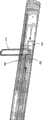
图1为示例性薄型外科缝合器的侧视图。Figure 1 is a side view of an exemplary low profile surgical stapler.
图2为薄型外科缝合器远端的侧剖视图,示出了布署缝钉之前的缝钉布署组件的第一实施例。2 is a side cross-sectional view of the distal end of a low profile surgical stapler showing the first embodiment of the staple deploying assembly prior to deploying staples.
图3为击发前的缝钉的分离等轴视图。Figure 3 is an isolated isometric view of a staple prior to firing.
图4为薄型外科缝合器远端的侧剖视图,示出了缝钉的成形和布署情况。Figure 4 is a side cross-sectional view of the distal end of a low profile surgical stapler showing staple formation and deployment.
图5A和5B分别为轴与缝钉布署组件连接处的剖视图。5A and 5B are respectively cross-sectional views of the connection between the shaft and the staple deploying assembly.
图6为示出轴与缝钉布署组件连接处的侧剖视图。6 is a side cross-sectional view showing the connection of the shaft to the staple deploying assembly.
图7A和7B分别为替代实施例的后视图和侧视图,示出了轴/缝钉布署组件与柄部组件的连接处。7A and 7B are rear and side views, respectively, of an alternative embodiment showing the connection of the shaft/staple deploying assembly to the handle assembly.
图8为根据替代实施例的示例性薄型外科缝合器的侧视图。8 is a side view of an exemplary low profile surgical stapler according to an alternative embodiment.
图9为图8所示薄型外科缝合器远端的等轴视图,示出了布署缝钉前缝钉布署组件的第二实施例。Figure 9 is an isometric view of the distal end of the low profile surgical stapler shown in Figure 8, showing a second embodiment of the staple deploying assembly prior to deploying the staples.
图10为图8所示第二实施例的侧剖视图,其中缝合器轴被移除。Figure 10 is a side cross-sectional view of the second embodiment shown in Figure 8 with the stapler shaft removed.
图11为第二缝钉布署实施例的局部等轴视图,示出了处于完全布署位置的缝钉和缝钉驱动器。11 is a partial isometric view of the second staple deploying embodiment, showing the staples and staple drivers in a fully deployed position.
图12为薄型外科缝合器远端的等轴视图,示出了释放前的处于布署位置的缝钉。12 is an isometric view of the distal end of a low profile surgical stapler showing staples in a deployed position prior to release.
图13至19示出了根据结合图1至7公开的实施例的缝钉布署过程中的各个步骤。13-19 illustrate various steps in a staple deployment process according to the embodiments disclosed in connection with FIGS. 1-7.
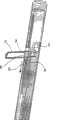
图20为第二示例性薄型外科缝合器的侧视图,示出了开放的远例轴末端。20 is a side view of a second exemplary low profile surgical stapler showing the open distal shaft end.
图21A为缝合器轴远端的侧剖视图,示出了布署前的第三缝钉布署组件实施例。21A is a side cross-sectional view of the distal end of a stapler shaft showing a third staple deploying assembly embodiment prior to deployment.
图21B为缝合器轴远端的顶部剖视图,示出了布署前的第三缝钉布署组件实施例。21B is a top cross-sectional view of the distal end of the stapler shaft showing the third staple deploying assembly embodiment prior to deployment.
图22为缝合器轴远端的顶视图,示出了布署过程中向前推进并旋转90°的砧块和缝钉成形器。22 is a top view of the distal end of the stapler shaft showing the anvil and staple former advanced and rotated 90° during deployment.
图23为缝合器轴远端的顶视图,示出了布署到多个组织层内的缝钉。23 is a top view of the distal end of the stapler shaft showing staples deployed into multiple tissue layers.
图24至35示出了与使用结合图20-33公开的外科缝合器的使用相关的步骤。Figures 24 to 35 illustrate the steps associated with using the surgical stapler disclosed in connection with Figures 20-33.
图36A-36H示出了第四缝钉布署组件实施例的击发顺序。36A-36H illustrate the firing sequence of the fourth staple deploying assembly embodiment.
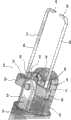
图37为薄型外科缝合器的侧视图,示出了第五缝钉布署组件实施例。37 is a side view of a low profile surgical stapler showing a fifth staple deploying assembly embodiment.
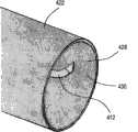
图38为由胃脘壁形成的双组织褶皱的示意图。Figure 38 is a schematic illustration of a double tissue fold formed by the gastric cavity wall.
图39为示出胃缩容手术过程中的第一或第二缝钉布署组件实施例的示意图。39 is a schematic diagram illustrating the first or second staple deploying assembly embodiment during a gastric volume reduction procedure.
图40为示出胃缩容手术过程中的第四缝钉布署组件实施例的示意图。40 is a schematic diagram illustrating a fourth staple deploying assembly embodiment during a gastric volume reduction procedure.
具体实施方式Detailed ways
本文公开了本发明的详细实施例。然而应当理解,公开的实施例仅仅是本发明的示例,本发明可以体现为各种不同的形式。因此,本文所公开的详细信息不应理解为限制,而仅是作为指导本领域技术人员如何制作和/或使用本发明的基础。Detailed embodiments of the invention are disclosed herein. It should be understood, however, that the disclosed embodiments are merely exemplary of the invention, which may be embodied in various different forms. Therefore, the details disclosed herein are not to be interpreted as limiting, but merely as a basis for teaching one skilled in the art how to make and/or use the invention.
根据本发明并结合图1至4公开了外科缝合器10,该缝合器用于在胃缩容手术过程中将紧固件12递送至组织部位,例如胃部。本专利申请公开的各个实施例涉及提供薄型外科缝合器10,该缝合器允许将大尺寸的紧固件或缝钉12经较小的开口或孔递送至体腔内。因此可以想到,本发明可以结合腹腔镜手术(即涉及经在体内形成的小开口进入(例如通过使用套管针进入皮肤)的外科手术)或内窥镜手术(即涉及通过经自然孔口(例如经口腔)递送的外科器械而进入的外科手术)使用。A
术语“大尺寸”旨在表示尺寸远大于用于到达手术部位的套管针孔或身体自然孔口的缝钉或紧固件。由图12可知,缝钉12的钉脚98和100比外科缝合器10的轴22的直径长。图22也示出了缝钉12的宽度如何比缝钉从中伸出的缝合器410的轴422的宽度宽。根据本发明,能够递送其长度比递送孔或身体自然孔口的直径大的缝钉(而在现有缝合器或其他紧固件递送装置中,由缝钉或紧固件的尺寸决定套管针孔的尺寸)。一种开放皮肤缝合装置使用大尺寸紧固件,该装置会被认为尺寸太大而不适合从5mm的套管针孔内向下递送。然而,本发明允许与该开放皮肤缝合装置一起使用的缝钉尺寸大致相同的缝钉从5mm的套管针孔内向下递送。就缝钉尺寸的工业标准而言,当今的外科手术中使用的缝钉尺寸有许多种。一种皮肤缝合器使用线径大约0.56mm的缝钉,而一种内部切割缝合器则使用线径小至大约0.17mm的缝钉。皮肤缝合器上的缝钉冠宽度为6mm,而内部切割缝合器所用冠宽度则为约2.5mm。如下文将详细讨论的,本发明的概念是在体腔内使用大尺寸缝钉(例如在皮肤缝合器中),并通过尺寸小于缝钉本身的套管针孔或身体自然孔口(例如5mm的套管针)进行递送。The term "oversized" is intended to mean staples or fasteners that are much larger in size than a trocar hole or natural body orifice used to reach a surgical site. As can be seen from FIG. 12 , the legs 98 and 100 of the
外科缝合器10的远侧布署端14具有合适的尺寸,可以在微创外科手术过程中穿过小的(例如5mm)套管针孔或柔性内窥镜。本发明的薄型外科缝合器10使得通过小进入孔在体腔内将较大面积的组织接合到一起成为可能。在体腔内,可以放置外科缝合器10将多层组织固定到一起,例如以在胃缩容手术过程中缩小胃脘的有效容积的方式实施。虽然本文所公开的本发明的外科缝合器10用于进行胃缩容手术,但在不脱离本发明精神的前提下,可使用本发明的外科缝合器10进行多种外科手术。The
图1、2和4示出了根据本发明的优选实施例的、将大缝钉12发射到多个组织层内的薄型外科缝合器10。外科缝合器10包括柄部16,柄部16具有形状适合外科医生抓握的手枪式握把18。扳机20可活动地连接到柄部16,用于在布署缝钉过程中拉向手枪式握把18。细长的管轴22从柄部16向远侧延伸。管轴22包括近端24和远端26,近端24固定在柄部16上,从远端26可以根据本发明并如下文详细讨论的那样布署缝钉12。Figures 1, 2 and 4 illustrate a low profile
缝钉布署组件28设置在轴22的内部30,用于从外科缝合器10的远端14发射缝钉12。根据下文的公开内容可知,缝钉布署组件28支撑缝钉12,使得缝钉12的纵轴线与轴22的纵轴线对齐,从而允许按上述方式布署大尺寸缝钉12。更具体地讲,轴22包括位于轴22的远端26的侧向布署口32,该布署口通过与轴22的封闭远侧末端34相邻的轴22的侧面延伸。布署口32在轴的纵轴线方向伸长,因此其形状和尺寸设定成允许从轴22内经布署口32向相邻组织内布署缝钉12。A
根据优选实施例,轴22具有小于约5mm的直径,以便于在内窥镜或腹腔镜手术过程中经套管或套管针(未示出)插入轴22。根据下文的公开内容可知,扳机20便于经轴22推进缝钉12,同时便于外科缝合器10从轴22的远端26进行布署。根据替代实施例可以想到,可以将独立的扳机或致动机构装入外科缝合器内,以经轴递送缝钉,并从轴向外布署缝钉,使其经布署口进入相邻组织内。According to a preferred embodiment,
在外科手术应用中,将外科缝合器10通过套管针或内窥镜操纵到所需位置,在该位置处沿轴22远端26的布署口32被推靠在待紧固的组织区域上。为了便于对着所选组织区域设置布署口32,轴22可旋转地固定在柄部16上,并且在柄部16上设有旋钮36。旋钮36包括中心孔38,轴22穿过该中心孔延伸。旋钮中心孔38内部的凸台(未示出)与轴22外表面(未示出)的凹口或狭槽(未示出)接合。当旋钮36旋转时,轴22也通过旋钮凸台与轴22的相互作用而相应旋转。当轴22旋转时,布署32的位置相对于周围组织在圆周方向变化,从而对着组织的不同区域重新设置布署口32。应当理解,旋钮36与轴22内部的缝钉布署组件28之间也存在连接,使得旋钮36的旋转也使缝钉布署组件28围绕轴22的纵轴线旋转。In surgical applications, the
参见图5A、5B、6、7A和7B,公开了这样一种机构,该机构在轴22以类似方式旋转时用旋钮36旋转缝钉布署组件28,而不需旋转外科缝合器10近端处的柄部16。根据本发明的优选实施例,当扳机20作用于缝钉布署组件28时,通过沿轴22的轴线前推或后拉的运动实现对缝钉12的击发。如下文详述,这种线性运动与扳机20相关联,以产生使缝钉12成形的足够大的杠杆作用力。必须允许该线性运动在扳机20和缝钉布署组件28的旋转部分之间旋转,使得使用者不需旋转手腕就可将缝钉布署组件28的布署口32与组织对齐。Referring to Figures 5A, 5B, 6, 7A and 7B, a mechanism is disclosed that rotates the
根据优选实施例并结合图5A和5B,扣环118用来将轴22的远端连接到缝钉布署组件28,具体地讲,连接到从缝钉布署组件28近端伸出的连接柱120。扣环118包括凸起122,用于沿连接柱120接合细长的凹槽124,以确保轴22的旋转可以本发明的外科缝合器10的使用者希望的方式引起连接柱120的旋转,同时又允许连接柱120线性运动,以将扳机20的线性运动传递至缝钉布署组件。根据结合图6所示的替代实施例,定位螺钉126用来根据本发明以促动旋转的方式将轴22连接到连接柱120,同时又允许连接柱120线性运动,以将扳机20的线性运动传递至缝钉布署组件。无论采用扣环118或定位螺钉126,轴22都通过轭架128固定到扳机20,以允许轴22相对于扳机20旋转,同时又允许连接柱120在启动扳机20时线性运动,以根据本发明使缝钉12成形(参见图7A和7B)。According to a preferred embodiment and with reference to FIGS. 5A and 5B , buckle 118 is used to connect the distal end of
图2和4示出了轴22的远侧部分,其中示出了根据本发明的第一实施例的缝钉布署组件28。根据本实施例,第一缝钉驱动器44纵向延伸穿过轴22的内部30。第一缝钉驱动器44包括近端46和远端48。第一缝钉驱动器44的近端46连接到驱动组件,即连接到直接通过扳机20启动的连接柱120(如结合图5A、5B、6、7A和7B所示和上文所讨论的),如箭头所示。简言之,如上所述,这种连接允许轴22随旋钮36旋转,以调节缝钉布署组件28和布署口32的取向,同时又允许第一缝钉驱动器44和第二缝钉驱动器56在扳机20控制下线性运动。外科缝合器的柄部不旋转。2 and 4 illustrate a distal portion of
驱动组件由扳机20开动,用于以下文详细讨论的方式可控制地将缝钉12紧固到所需的组织位置。第一缝钉驱动器44的远端48包括面向近侧的凸轮表面50,该凸轮表面被成形为相对于第一缝钉驱动器44的纵轴线成一角度。此外,第一缝钉驱动器44的远端壁52包括倾斜表面,该倾斜表面被成形为相对于第一缝钉驱动器44的纵轴线成一角度。远端壁52的取向角度在轴22的远侧末端34处与倾斜的内表面54一致,使得第一缝钉驱动器44的远端壁52在击发前位于轴22的远侧末端34内。轴22的远侧末端34用于将第一缝钉驱动器44的远端48容纳在轴22内。The drive assembly is actuated by
第二缝钉驱动器56也从驱动组件(未示出)经轴22向远侧延伸到刚好位于布署口32近端。第二缝钉驱动器56还包括连接到驱动组件的近端58以及远端60。第二缝钉驱动器56受驱动组件控制,以便在根据本发明折叠和布署缝钉12的过程中沿轴22的纵轴线向远侧推进。第二缝钉驱动器56的远端60包括面向远侧的凸轮表面62,该凸轮表面被成形为相对于第二缝钉驱动器56的纵轴线成一角度。A
第一弯曲臂64和第二弯曲臂66纵向设置在轴22的内部30。第一弯曲臂64和第二弯曲臂66取向为面向布署口32,使得缝钉12在折叠和随后从布署口32射出过程中能够支撑在弯曲臂上。第一弯曲臂64和第二弯曲臂66在枢转点68处连接在一起,以便在布署口32方向上彼此相对旋转。销轴70从枢转点68延伸到轴22的内壁72,以将第一弯曲臂64和第二弯曲臂66的枢转点68附连到轴22上,从而防止布署过程中第一弯曲臂64和第二弯曲臂66在外科缝合器10的轴22内纵向滑动。第一弯曲臂64和第二弯曲臂66相对的自由端各自包括在离开布署口32的方向上延伸的楔形边缘74和76。如上所述,第一缝钉驱动器44和第二缝钉驱动器56各自包括面向第一弯曲臂64的楔形边缘74的凸轮表面50和面向第二弯曲臂66的楔形边缘76的凸轮表面62。第一缝钉驱动器44的凸轮表面50和第二缝钉驱动器56的凸轮表面62的斜度与第一弯曲臂64的楔形边缘74和第二弯曲臂66的楔形边缘76的斜度相同,以使得弯曲臂64和66的自由端在击发过程中滑动接触第一缝钉驱动器44的凸轮表面50和第二缝钉驱动器56的凸轮表面62。The
为了击发本发明的外科缝合器10,首先将缝钉12经轴22传送至面对布署口32的布署位置。传送缝钉12时,缝钉12的长度沿轴22的纵轴线设置。根据优选实施例,缝钉12通过一系列锁扣穿梭运动沿轴22传送。腹腔镜式夹置放器采用了根据本发明使用的优选穿梭运动,例如参见美国专利No.4430997(请参见图4a、4b、5a、5b、6a和6b),该专利以引用方式并入本文中。‘997号专利描述了一种实现连续送夹的往复运动(根据本发明的外科缝合器)的机构。需要顶部支承和底部支承,这些长条支承各自具有齿或坡道,以使缝钉只能向远侧送进。当顶部或底部往复运动时,每往复运动一次,缝钉都被推进一个全行程。通过这种方式,可以将一整叠缝钉一起推进。To fire the
各个缝钉12可以被装载到外科缝合器10内,并经轴22推进。作为另外一种选择,可以将钉仓(未示出)预装到外科缝合器10内,从而在每次击发外科缝合器10时,将缝钉12单独地从钉仓移动至布署口32。图3为缝钉12的分离视图,详细地示出了缝钉12的初始的击发前结构。如图3所示,缝钉12包括具有纵轴线的长主体段78。第一叉尖80和第二叉尖82位于主体段78的相对端并且在与主体段78的纵轴线基本上垂直的方向上延伸。第一叉尖80和第二叉尖82在基本上相同的方向上延伸。根据优选实施例,第一叉尖80和第二叉尖82优选地从主体段78以90°角弯曲,以便于缝钉12在击发过程中进入组织。第一叉尖80和第二叉尖82各自包括用于刺穿组织的锋利末端84和86。
在主体段78的中段形成四个大约90°的弯头88、90、92和94。主体段78内的这些弯头88、90、92和94在缝钉12中间形成“框”区96。弯头88、90、92和94成形于主体段78内,使得框96的平面垂直于第一叉尖80和第二叉尖82所在的平面。框96将主体段78分成一对钉脚98和100。框96便于缝钉12经轴22推进至面对布署口32的布署位置内。另外,当缝钉12在布署过程中成形时,框96提供了对缝钉12的控制。Four approximately 90° bends 88 , 90 , 92 and 94 are formed in the middle of the body section 78 . These bends 88 , 90 , 92 and 94 within body section 78 form a “box” region 96 in the middle of
如图2和4所示,本发明的外科缝合器10的端部操纵装置102包括可活动支柱104,用于定位相邻的布署口32并与第一弯曲臂64和第二弯曲臂66对齐。可以想到,在某些构造中,支柱可以固定在轴内,缝钉可以在支柱上上下穿梭运动以进行布署。布署过程中传送和弯曲缝钉12时,支柱104在框96处支撑缝钉12。支柱104具有可与缝钉12的类似形状的框96配合的矩形形状。具体地讲,支柱104包括四个向上延伸的侧壁106、108、110和112,并且被成形为可落入由沿主体段78的中部形成的框96限定的空间内。支柱104与框96之间的配合既足够紧,可以使缝钉12在传送和弯曲过程中保持在固定位置;而又不扣紧,以至于缝钉12在弯曲后无法脱离支柱104。根据优选实施例,支柱104成形于推杆116的远端114,推杆116经轴22在钉仓(未示出)与布署口32之间纵向驱动。As shown in FIGS. 2 and 4 , the
参见图13-19,下文结合图8-12公开的实施例揭示了用于布署缝钉的机构,该机构被认为适合与本实施例结合使用,然而并未在文中重复。简言之,锁杆在支柱和缝钉上滑动,以在缝钉击发前锁定其位置。在缝钉击发时,锁杆将沿缝钉主体段的中部固定就位。在刚击发后而还未从组织脱离时,向后拉动锁杆。Referring to Figures 13-19, the embodiments disclosed below in conjunction with Figures 8-12 disclose mechanisms for deploying staples that are considered suitable for use in conjunction with the present embodiments, but are not repeated herein. Briefly, the locking bar slides over the posts and staples to lock the staples in place before they are fired. When the staple is fired, the locking bar will be held in place along the middle of the staple body section. Just after firing but not yet disengaged from the tissue, pull the locking lever back.
在采用钉仓设计的情况下,将利用穿梭推进机构设计使缝钉从近侧轴内向击发位置穿梭运动。在击发位置,缝钉将移出递送平面到下方的框96附近并进入框96。In the case of a cartridge design, a shuttle advance mechanism design would be utilized to shuttle the staples from the proximal shaft inwardly to the fired position. In the fired position, the staples will move out of the delivery plane to adjacent frame 96 below and into frame 96 .
在初始布署步骤中,缝钉12移到支柱104上,并且通过在推杆116控制下将支柱104移动到刚好位于布署口32内的位置处,将缝钉12经轴22纵向传送。当根据本发明的优选实施例通过移动支柱104而经轴22传送缝钉12时,可以想到,可以直接将缝钉12放至支柱104处。缝钉12与框96一起设置在与布署口32平行的平面内,并且第一叉尖80和第二叉尖82在布署口32方向垂直于框96延伸。在该位置,第一叉尖80和第二叉尖82已准备好在本发明的外科缝合器10击发时以垂直角度进入邻近布署口32的组织内。In an initial deployment step,
当启动扳机20以布署缝钉12时,第一缝钉驱动器44受力,用于在轴22内朝近侧将第一缝钉驱动器44拉向第一弯曲臂64。与此同时,第二缝钉驱动器56受力,用于朝远侧将第二缝钉驱动器56推向第二弯曲臂66。当缝钉驱动器44和56在轴22内会聚时,第一缝钉驱动器44的凸轮表面50和第二缝钉驱动器56的凸轮表面62分别与第一弯曲臂64的楔形边缘74和第二弯曲臂66的楔形边缘76接合。第一缝钉驱动器44和第二缝钉驱动器56同时分别作用于第一弯曲臂64的楔形边缘74和第二弯曲臂66的楔形边缘76的反向力使第一弯曲臂64和第二弯曲臂66在布署口32方向上彼此相对枢转。当第一弯曲臂64和第二弯曲臂66枢转时,第一弯曲臂64和第二弯曲臂66与缝钉主体段78的两个相对侧接合,从而在缝钉12内产生弯曲作用。当缝钉12的两侧弯曲时,缝钉12的框96被支柱104和锁杆牢固保持在位置上(如上所述)。支柱104的支承加上第一弯曲臂64和第二弯曲臂66的向内枢转作用迫使缝钉12在邻近框96的位置弯曲。缝钉12弯曲,使得主体段78的两个侧边(即钉脚)98和100经布署口32向外弯转,如图2和4的虚线所示。通过如上所述在弯曲过程中锚固缝钉12中段(即框96)和锁杆,支柱104确保缝钉12的侧边在框96附近(而非沿主体段78长度的另一个位置处)弯曲。在缝钉成形过程中,通过将支柱104和锁杆保持在框96上,也可以防止缝钉12过早经布署口32释放。支柱104和锁杆确保在经布署口32发射缝钉12之前、缝钉12的侧边完全弯曲到在布署口32处与组织接合。When
图4示出了在第一缝钉驱动器44的凸轮表面50和第二缝钉驱动器56的凸轮表面62被充分推进到与第一弯曲臂64和第二弯曲臂66接合之后的轴22的远端26。如图2和4所示,在该位置缝钉12的侧边完全向内弯曲,使得第一叉尖80和第二叉尖82经布署口32刺穿组织。在缝钉12完全成形并被推入相邻组织后,支柱104脱离框96,以穿过布署口32发射缝钉12。参见图13至19并如上文所述,击发缝钉前锁杆在支柱104和缝钉12上滑动,以将缝钉12锁定在合适位置。在击发缝钉过程中,锁杆将缝钉12主体段78的中部保持在位置,而在缝钉刚击发后而还未脱离组织时拉回锁杆。通过相对于扣紧的组织向下(并在远离组织方向)拉动外科缝合器10使支柱104脱离缝钉12,以致从框96内拉下支柱104。当缝钉12离开外科缝合器10时,缝钉12保留在组织内。发射缝钉12之后,可以将外科缝合器10的远端14重新定向到组织层的另一区域,或可通过旋钮36旋转轴22,以将另外的缝钉12布署进组织接合处。4 shows the distal end of the
图8、9、10、11A、11B和12示出了根据替代实施例的外科缝合器的轴222的远端214。类似结合图1至4所示的前一实施例,外科缝合器210包括柄部216,柄部216具有形状适合外科医生抓握的手枪式握把218。扳机220可活动地连接到柄部216,用于在布署缝钉过程中拉向手枪式握把218。细长的管轴222从柄部216向远侧延伸。管轴222包括近端224和远端226,近端224固定于柄部216,从远端226可以根据本发明并如下文详细讨论的那样布署缝钉212。8, 9, 10, 11A, 11B and 12 illustrate the
缝钉布署组件228设置在轴222的内部230,用于从外科缝合器210的远端214发射缝钉212。更具体地讲,轴222包括位于其远端226的侧向布署口232。布署口232的形状和尺寸设定成允许将缝钉212从管轴222内经由布署口232布署到相邻组织内。布署口232位于轴222的远端226,并且通过与轴222的封闭远侧末端234相邻的轴222的侧面延伸。A
参见图13-19并如上文所述,公开了用于将缝钉212保持在与布署口232相邻的合适位置的机构。简言之,锁杆330在支柱304和缝钉212上滑动,以在击发缝钉前将其锁定在合适位置。在击发缝钉时,锁杆330将沿着缝钉212主体段278的中部固定就位。在刚击发后而还未与组织脱离时,向后拉动锁杆330。13-19 and as described above, a mechanism for maintaining
在采用钉仓设计的情况下,使用穿梭推进机构设计使缝钉从近侧轴内穿向击发位置。在击发位置,缝钉将移出递送平面到下方的框96附近并进入框96。In the case of a cartridge design, a shuttle advance mechanism design is used to pass the staples from within the proximal shaft to the fired position. In the fired position, the staples will move out of the delivery plane to adjacent frame 96 below and into frame 96 .
根据优选实施例,轴222具有小于约5mm的直径,以允许在内窥镜或腹腔镜手术过程中经套管或套管针(未示出)插入轴222。根据下文的公开内容可知,扳机220便于经轴222推进缝钉212,并且便于从轴222的远端226布署手术缝钉212。根据替代实施例可以想到,可以将独立的扳机或致动机构装入外科缝合器内,以经轴递送缝钉,并从轴向外布署缝钉,使其经布署口进入相邻组织内。According to a preferred embodiment,
在外科手术应用中,将外科缝合器210通过套管针或内窥镜操纵到所需位置,在该位置处沿轴222远端226的布署口232被推靠在待紧固组织区域。为了便于对着所选组织区域设置布署口232,轴222可旋转地固定到柄部216,并在柄部216上设置旋钮236。旋钮236包括中心孔238,轴222穿过该中心孔延伸。旋钮中心孔238内部的凸台(未示出)与轴222外表面(未示出)的凹口或狭槽(未示出)接合。当旋钮336旋转时,轴222也通过旋钮凸台与轴222的相互作用而相应旋转。当轴222旋转时,布署口232的位置相对于周围组织在圆周方向变化,从而对着组织的不同区域重新设置布署口232。应当理解,旋钮236与轴222内部的缝钉布署组件228之间也存在连接,以使得旋钮236的旋转也会使缝钉布署组件228围绕轴222的纵轴线产生旋转。参见图5A、5B、6、7A和7B,并如上文基于结合图1至4公开的前一实施例所描述的,揭示了一种利用旋钮236旋转缝钉布署组件228的机构,以在不旋转外科缝合器210近端处的柄部216的情况下,允许使用扳机220来启动缝钉布署组件228。根据本发明的优选实施例,通过沿轴222的轴线的前推或后拉的运动实现对缝钉212的击发。如下文详述的,这种线性运动与扳机220相关联,以产生使缝钉212成形的足够大的杠杆作用力。必须允许该线性运动在扳机220和装置(即缝钉布署组件228)的旋转部分之间旋转,使得使用者不需旋转手腕就可将缝钉布署组件228的布署口232与组织对齐。In surgical applications, the
根据优选实施例,扣环用来将轴222的远端连接到缝钉布署组件228,具体地讲,连接到从缝钉布署组件近端伸出的连接柱。扣环包括沿连接柱与凸起接合的凹槽,确保轴的旋转会使连接柱以本发明的外科缝合器10的使用者期望的方式旋转。根据替代实施例,使用定位螺钉以便于根据本发明以旋转的方式将轴222连接到连接柱。无论采用扣环或定位螺钉,轴都通过轭架固定到扳机,以允许连接柱相对于扳机旋转,同时又允许连接柱在启动扳机时线性运动,以根据本发明使缝钉成形。本实施例的缝钉布署组件228所采用的缝钉212同样与侧向布署口232相对地在轴222内纵向对齐。纵向对齐缝钉212允许经较小直径的轴222发射大缝钉212。第一缝钉驱动器244经轴222纵向延伸而超出缝钉212的远侧叉尖280。第一缝钉驱动器244包括连接到驱动组件的近端246和具有面向近侧的凸轮表面250的远端248。第二缝钉驱动器256位于缝钉212近侧,并邻近近端缝钉叉尖282。第二缝钉驱动器256包括连接到驱动组件的近端258和具有面向远侧的凸轮表面262的远端260。如图13-19所示,第一缝钉驱动器244和第二缝钉驱动器256的倾斜表面使凸轮表面250和262可更充分地靠近,并允许缝钉212更倾斜地成形。缝钉仍在倾斜表面上形成,增加的凹口结构有助于使凸轮表面会合到一起。According to a preferred embodiment, a buckle is used to connect the distal end of
如前一实施例一样,缝钉212包括具有纵轴线的长主体段278。第一叉尖280和第二叉尖282位于主体段278的相对端并且在与主体段278的纵轴线基本上垂直的方向上延伸。第一叉尖280和第二叉尖282在基本上相同的方向上延伸。根据优选实施例,第一叉尖280和第二叉尖282优选地与主体段278成90°角弯曲,以便于缝钉212在击发过程中进入组织。第一叉尖280和第二叉尖282各自包括用于刺穿组织的锋利末端。As in the previous embodiment,
在主体段278的中段形成四个大约90°的弯头288、290、292和294。主体段278内的这些弯头288、290、292和294在缝钉212中间形成“框”区296。弯头288、290、292和294成形于主体段278内,使得框296的平面垂直于第一叉尖280和第二叉尖282所在的平面。框296将主体段278分成一对钉脚298和300。框296便于缝钉212经轴222推进至布署口232对面的布署位置内。另外,当缝钉212在布署过程中成形时,框296提供了对缝钉212的控制。Four approximately 90° bends 288 , 290 , 292 and 294 are formed in the middle of the
如前一实施例一样,提供了支柱304,用于在布署过程中传送和弯曲缝钉212时在框296处支撑缝钉212。支柱304具有与缝钉的类似形状的框相配合的矩形形状。具体地讲,支柱304包括四个向上延伸的侧壁306、308、310和312,并且被成形为可安放在沿主体段278的中部形成的框296限定的空间内。支柱304与框296之间的配合既足够紧,可以使缝钉212在传送和弯曲过程中保持在固定位置;而又不扣紧,以至于缝钉212在弯曲后无法脱离支柱304。根据优选实施例,支柱304成形于推杆316(未示出)的远端314,推杆316经轴222在钉仓与布署口232之间纵向驱动。As with the previous embodiment, struts 304 are provided for supporting
图13-19公开了用于此方法的机构。简言之,锁杆330在支柱304和缝钉212上滑动,以在击发缝钉212前将其锁定在合适位置。在击发缝钉时,锁杆330将沿着缝钉212主体段278的中部固定就位。在缝钉刚击发后而还未与组织脱离时,向后拉动锁杆330。在采用钉仓设计的情况下,使用穿梭推进机构设计使缝钉从近侧轴内穿向击发位置。在击发位置,缝钉将移出递送平面到下方的框96附近并进入框96。Figures 13-19 disclose the mechanism for this method. Briefly, locking
要根据该缝钉布署组件228击发缝钉212,需朝手枪式握把218手动枢转扳机220,从而向第一缝钉驱动器244和第二缝钉驱动器256施加击发力。当击发力施加到第一缝钉驱动器244和第二缝钉驱动器256时,第一缝钉驱动器244向近侧朝缝钉212的一侧推进,而第二缝钉驱动器256则向远侧朝缝钉212的另一侧推进。当第一缝钉驱动器244和第二缝钉驱动器256紧靠缝钉212的相对侧会聚时,第一缝钉驱动器244的凸轮表面250和第二缝钉驱动器256的凸轮表面262分别使缝钉212的倾斜叉尖280和282接合。由于缝钉212中段被框296内的支柱304锁定在合适位置,所以第一缝钉驱动器244的凸轮表面250和第二缝钉驱动器256的凸轮表面262与缝钉212的倾斜叉尖280和282之间的接触在缝钉212的侧边即钉脚298和300内产生弯曲作用。缝钉212中部受框296和锁杆330约束。当缝钉驱动器244和256紧靠缝钉212的相对侧会聚时,缝钉钉脚不受约束的部分必然发生弯曲。当第一缝钉驱动器244和第二缝钉驱动器256在缝钉212侧边继续会聚时,缝钉212的侧边通过布署口232而彼此相对地弯曲,从而分别将第一叉尖280和第二叉尖282压入相邻组织。当第一缝钉驱动器244和第二缝钉驱动器256被推入其最近侧和最远侧位置(如图11和12所示)时,缝钉212被完全弯曲,使得主体段278的侧边经布署口232垂直于框296延伸。在该位置,第一叉尖280和第二叉尖282在组织层内充分弯曲成闭环,从而将组织层锁定在一起。类似上文结合图1至4所公开的第一实施例,该第二缝钉布署组件228允许从细长轴222的侧布署口232发射大缝钉212。然而,在该组件中,第一缝钉驱动器244和第二缝钉驱动器256直接作用于缝钉212的侧边,因而不需要使用弯曲臂。To fire the
图20-35示出了根据本发明的缝钉布署组件428的第三实施例。如结合图1至4所示的上述实施例一样,外科缝合器410包括柄部416,柄部416具有形状适合外科医生抓握的手枪式握把418。扳机420可活动地连接于柄部416,用于在布署缝钉过程中拉向手枪式握把418。由下列公开内容可知,柄部416包括第一可滑动旋钮526和第二可滑动旋钮528。最远侧旋钮(即第一旋钮526)控制附装在缝钉旋钮上的杆或线缆。近侧安装的第二旋钮528控制缝钉成形器462的旋转;在砧块旋钮528上附装有杆或线缆,用于致动外科缝合器410远端处的旋转砧块。旋钮526和528旋转90度之后,远侧缝钉旋转块和旋转砧块被锁紧到垂直于外科缝合器410轴线的位置内。在该位置处,扳机420与击发组件接合,以使砧块接触缝钉并将缝钉钉脚成形于和外科缝合器410的轴线平行的轴线内。20-35 illustrate a third embodiment of a
细长的管轴422从柄部416向远侧延伸。管轴422包括固定到柄部416的近端424和开放远端426,可以根据本发明并如下文详细讨论的那样从远端426布署缝钉412。An elongated
缝钉布署组件428设置在轴422的内部430,用于从外科缝合器410的远端414发射缝钉412。根据优选实施例,轴422具有小于约5mm的直径,以允许在内窥镜手术(即通过自然孔口(例如经口腔)进行的手术)或腹腔镜手术(即通过外科手术形成的开口(例如经套管针)进行的手术)过程中通过套管或套管针(未示出)插入轴422。根据下列公开内容可知,扳机420(或其他致动机构,例如滑动旋钮、杠杆或外科手术器械中常用的其他控制机构)便于缝钉412经轴422推进,并便于从轴422的开放远端426布署外科缝合器410。根据替代实施例可以想到,可以将独立的扳机或致动机构装入外科缝合器内,以经轴递送缝钉,并从轴向外布署缝钉,使其经布署口进入相邻组织内。A
根据本实施例,轴422包括位于其开放远端426处的用于发射缝钉412的开放远侧末端434,而不是如上述实施例一样的侧布署口。缝钉412完全经轴422纵向推进,以通过轴422的开放远侧末端434布署。在外科手术应用中,将外科缝合器410通过套管针或内窥镜操纵到所需位置,在该位置处轴422的开放远侧末端434被推靠在待紧固组织区域上。更具体地讲,在将缝钉412推入组织以击发前将其旋转到击发位置。实践中可以想到,利用一组抓紧器将组织折叠或褶皱拉到一起,然后将缝钉布署到整个组织褶皱上,并使缝钉成形以将组织褶皱固定到一起。According to the present embodiment, the
如图20-35所示,缝钉布署组件428包括缝钉旋转块444,其用于经轴422递送缝钉412。缝钉412基本上与上文结合图1至4所示实施例描述的相同。缝钉旋转块444包括中央支柱446,其用于接合缝钉412的框496,以在经轴422递送缝钉412的过程中将缝钉固定。缝钉旋转块444通过下推杆448经轴422递送。下推杆448轴向延伸而通过轴422的长度。下推杆448包括近端450和其上固定有缝钉旋转块444的远端452。下推杆448的近端450连接于柄部416内的驱动组件。该驱动组件以类似于对上文公开的实施例描述的方式起作用。支承454将缝钉旋转块444以枢转方式连接到下推杆448,并允许缝钉旋转块444在第一旋钮控制下相对于推杆448旋转。As shown in FIGS. 20-35 ,
缝钉旋转块444具有矩形形状,并且包括位于缝钉旋转块444较长端的第一弯曲导引件456和第二弯曲导引件458。第一弯曲导引件456和第二弯曲导引件458提供了一结构,在布署过程中围绕该结构可以使缝钉412成形。
缝钉旋转块444具有矩形形状,并且包括位于缝钉旋转块444较长端的第一弯曲导引件456和第二弯曲导引件458。第一弯曲导引件456和第二弯曲导引件458提供了一结构,在布署过程中围绕该结构可以使缝钉412成形。当被中心支架固定时,缝钉412的框496在第一弯曲导引件456和第二弯曲导引件458之间通过。缝钉412的钉脚498和500长于第一弯曲导引件456和第二弯曲导引件458,使得在布署过程中缝钉412的叉尖480和482可包绕第一弯曲导引件456和第二弯曲导引件458。
缝钉成形器462沿轴422的纵轴线驱动,以便于缝钉412在布署过程中围绕第一弯曲导引件456和第二弯曲导引件458弯曲。缝钉成形器462包括附接在连接构件468的相对侧上的第一成形块464和第二成形块466。第一成形块464和第二成形块466各自包括接触面470和472,接触面的形状和尺寸设定成可以如下文详细讨论的那样在弯曲过程中用于接合缝钉412。第一成形块464和第二成形块466之间的距离大于缝钉旋转块444较长端的长度,使得第一成形块464和第二成形块466可以越过缝钉旋转块444上各自的第一弯曲导引件456和第二弯曲导引件458。缝钉成形器462在轴422内由纵向延伸的上推杆474轴向驱动。上推杆474延伸而基本上通过轴422的长度,并且在近端476处连接到驱动组件。缝钉成形器462使缝钉412的钉脚498和500在布署过程中包绕第一弯曲导引件456和第二弯曲导引件458。Staple former 462 is driven along the longitudinal axis of
缝钉成形器462沿轴422的纵轴线驱动,以便于缝钉412在布署过程中围绕第一弯曲导引件456和第二弯曲导引件458弯曲。缝钉成形器462包括附接在连接构件468的相对侧上的第一成形块464和第二成形块466。第一成形块464和第二成形块466各自包括接触面470和472,接触面的形状和尺寸设定成可以如下文详细讨论的那样在弯曲过程中用于接合缝钉412。第一成形块464和第二成形块466之间的距离大于缝钉旋转块444较长端的长度,以使得第一成形块464和第二成形块466可以越过缝钉旋转块444上的第一弯曲导引件456和第二弯曲导引件458。缝钉成形器462在轴422内由纵向延伸的上推杆474轴向驱动。上推杆474延伸而基本上通过轴422的长度,并且在近端476处连接到驱动组件,如箭头所示。缝钉成形器462固定在上推杆474的远端520处。上推杆474包括垂直于上推杆474长度延伸的开口。连接构件524从缝钉成形器462伸出而穿过开口522,以将缝钉成形器462连接到上推杆474上,并构成使缝钉成形器462相对于上推杆474旋转的手段。上推杆474平行于下推杆448沿轴422的纵轴线延伸。上推杆474与下推杆448由缝钉成形器462隔开。当缝钉成形器462经轴422向远侧推进时,缝钉成形器462沿下推杆448的表面滑动。可以想到,可以用旋转锁紧器防止在击发和弯曲缝钉过程中缝钉成形器和/或缝钉旋转块发生任何旋转运动。可以想到,可以用摩擦锁紧装置或凹口可以实现这一目的,当足够的力施加到该装置上时,其中的部件会像齿轮齿一样啮合到一起。布署缝钉前,锁杆可向前滑动来锁紧这两种部件。Staple former 462 is driven along the longitudinal axis of
在将外科缝合器410插入身体之前,通过将下推杆448推至充分远侧位置而超出轴422的开放远端426,可以将缝钉412装载到缝钉旋转块444上。当缝钉旋转块444处于轴422以外时,通过将缝钉412的框496压向中心支架460,直到框496的侧面接触支架,可以将缝钉412装载到外科缝合器410内。装载缝钉412之后,下推杆448回缩到轴412内,以将缝钉旋转块444以及附装的缝钉412拉入缝合器轴422内部。将缝钉旋转块444和缝钉412缩回轴422内,同时各自的纵向长度沿轴422的轴线延伸。以这种方式装载缝钉412可使长得多的缝钉412能够装到小直径的缝合器轴422内。回缩时,缝钉412的远侧叉尖480刚好位于轴422的开放远端426内。The
当缝钉旋转块444以及附装的缝钉412位于轴422内部时,将外科缝合器410穿过小直径的套管针口或内窥镜插入体内,并到达体腔内的组织处。在合适的组织位置,用手扣动扳机420,以向远侧驱动下推杆448,并将缝钉412的整个长度暴露在轴422的开放远端426以外。在轴422之外,将缝钉旋转块444在第一旋钮控制下旋转90°,以将缝钉412取向为垂直于轴422的轴线并将缝钉叉尖480和482紧贴相邻组织,如图20至35所示。当缝钉412与组织对齐时,缝钉成形器462被上推杆474向远侧驱动至穿过轴422的开放远端426。在轴422之外,也将缝钉成形器462在第二旋钮的控制下旋转90°,以将缝钉成形器462的长度与露出的缝钉412的长度平行对齐。缝钉成形器462被上推杆474沿缝钉旋转块444的侧面向近侧驱动,如图23所示。With the staple rotation block 444 and attached
当缝钉成形器462沿缝钉旋转块444的侧面通过时,接触面470和472沿第一成形块464和第二成形块466在缝钉成形器462的侧面上推动并向内弯曲缝钉412的钉脚498和500,将缝钉叉尖480和482以及钉脚498和500驱动进组织层或组织褶皱内以固定褶皱。缝钉成形器连接构件468具有相对于第一成形块464和第二成形块466较薄的高度,使得当第一成形块464和第二成形块466推动并弯曲缝钉412的侧面时,连接构件468从缝钉412和缝钉旋转块444上方经过。在缝钉421已完全推入组织层之后,中央支柱446从框496回缩,以将缝钉412从外科缝合器410中释放。在发射缝钉412之后,缝钉成形器462重新旋转至与轴的轴线纵向对齐,并且被上推杆474向近侧拉回至轴422的内部430。缝钉旋转块444也重新旋转至与轴的轴线纵向对齐,并且向近侧回缩进轴422内。在缝钉成形器462和缝钉旋转块444均被拖入轴422内后,可以将外科缝合器410从体内取出以完成手术,或者重新装载另一个缝钉412,以进一步固定组织层。还可用缝钉进给装置将缝钉连续进给到装置的远端内。As the staple former 462 passes along the sides of the staple
图36A-36H示出了根据本发明的缝钉布署组件628的另一个实施例,该实施例类似于上文结合图20-35公开的缝钉布署组件。缝钉布署组件628将缝钉612纵向推出缝合器轴622的开放远端626。根据本实施例,缝钉612通过中央支柱646连接到下推杆648。下推杆648沿轴的轴线纵向传送缝钉612至轴622的开放远端626之外,如图36B至36H所示。当缝钉612的整个长度都伸出轴622外(如图36C所示)时,缝钉612由中央支柱646旋转90°,如图36D和36E所示。当缝钉612完全转到位时,缝钉612的主体段678横向于外科缝合器轴622的轴线,如图36E所示。外科缝合器610旋转后,缝钉612的叉尖680和682面向相邻的目标组织(未示出)。为了将叉尖680和682驱动至组织内,需将缝钉成形器662经轴622向远侧推进到开放远端626之外。缝钉成形器662具有第一竖直构件664和第二竖直构件666,它们中间隔有薄连接构件668。第一竖直构件664和第二竖直构件666各自包括接触面670和672,接触面的形状和尺寸设定成可以如下文详细讨论的那样在弯曲过程中接合缝钉612。当缝钉成形器662向远侧推进时,第一竖直构件664的接触面670和第二竖直构件666的接触面672在框696的两侧推挤缝钉612,以向前弯曲缝钉钉脚698和700,如图36G所示。当缝钉成形器662完全伸展时,缝钉612弯曲,使得叉尖680和682扎入组织而形成锁缝接合,如图36G和36H所示。缝钉612成形之后,缝钉成形器662向近侧回缩至轴622内,如图36H所示。然后扭转缝合器轴622,使得外科缝合器610从支柱拉脱,以从中央支柱646发射缝钉612。作为另外一种选择,为了发射缝钉,可以设置一个机构(未示出)将支柱下拉至推杆内,使得支柱与框分离。发射缝钉之后,将下推杆向近侧拉回缝合器轴内。36A-36H illustrate another embodiment of a
图37示出了根据本发明的缝钉布署组件828的另一个实施例。根据本实施例,布署用于将多个组织层紧固在一起的螺旋缝钉812。轴向地布署缝钉812到轴822的开放远端826外。缝钉812优选地是直径为3/16”的拉成螺旋形的盘圈,该盘圈由镍钛诺或其他形状记忆材料制成。外科缝合器810包括锋利末端880,其位于面向发射口的盘圈812末端,即缝合器轴822的开放远端826。为了将组织层紧固到一起,需将细长的管轴822穿过较小(5mm)的套管针并插入腹腔。外科缝合器810进入腹腔后,对其进行操纵,以使得开放的轴末端826紧贴待紧固的组织层。然后致动扳机816,以将缝钉812的锋利末端880经轴开口826刺入组织内。当末端880位于组织内时,旋转外科缝合器810的驱动机构,以旋转缝钉812的螺旋线,并将缝钉末端880进一步驱动至组织内。缝钉812被完全驱动至组织层内之后,缝钉812从外科缝合器810释放。FIG. 37 illustrates another embodiment of a
现在来关注薄型外科缝合器在治疗病态肥胖症的胃缩容手术(GVR)中的示例性应用。胃缩容手术涉及在胃前面形成褶皱,其中褶皱内翻至胃内。结果导致胃内空间被该褶皱占据。手术留下小的套管状区域,食物可以在该区域处向远侧通过缩容后的胃。在本实例中,通过双组织褶皱形成套管。在双组织褶皱中,沿胃小弯两侧的组织被拉入胃脘内。在胃脘内,组织一侧被折叠并包绕在内窥镜管或之前已进入胃脘的其他管状结构周围。然后将胃壁的第二部分从管的相对侧拉入胃脘,并且折叠和回拉,使其经过整个内窥镜管,从而覆盖组织的第一褶皱。将组织的第一褶皱和第二褶皱固定在一起,形成双褶皱套管,如图-所示。在此类双组织折叠手术中,需要极好地紧固两个独立的褶皱,以允许接触的粘膜层愈合在一起。由于双褶皱基本上涉及拉到一起的四层组织,因此需要较大的紧固件,以将全部四层牢牢地紧固在一起。过去,递送尺寸足够大的紧固件以固定所有组织层需要较大的套管针或切口,这样才可以将足够大的外科缝合器穿入体腔。使用薄型外科缝合器可以将多个组织层固定在一起(如图所示),并将大缝钉穿过小得多的套管针口。Attention is now directed to an exemplary application of a low profile surgical stapler in gastric volume reduction surgery (GVR) for the treatment of morbid obesity. Gastric reduction surgery involves creating a fold on the front of the stomach, where the fold turns inward into the stomach. The result is that the stomach space is taken up by this fold. The surgery leaves a small sleeve-like area where food can pass distally through the reduced stomach. In this example, the cannula is formed by a double tissue fold. In a double tissue fold, tissue along the sides of the lesser curvature is pulled into the gastric cavity. Inside the gastric cavity, one side of the tissue is folded and wrapped around the endoscope tube or other tubular structure that has previously entered the gastric cavity. A second portion of the stomach wall is then pulled into the gastric cavity from the opposite side of the tube, and folded and pulled back across the entire endoscopic tube, covering the first fold of tissue. Pin the first and second folds of tissue together to form a double-fold cannula, as shown in Fig. In such double-tissue plication procedures, excellent fastening of the two separate folds is required to allow the contacting mucosal layers to heal together. Since a double pleat basically involves four layers of tissue pulled together, larger fasteners are required to securely fasten all four layers together. In the past, delivering fasteners of sufficient size to secure all tissue layers required large trocars or incisions in order to pass a large enough surgical stapler into the body cavity. Multiple tissue layers can be held together using low-profile surgical staplers (as shown) and large staples can be threaded through the much smaller trocar port.
要将多层胃组织固定到一起,需将外科缝合器的轴从已经穿过腹壁或胃壁的5mm套管针中穿过。将外科缝合器的远侧末端插入胃脘,并将其操纵至靠近胃小弯的位置处。在该手术过程中,将柔性的胃镜经食道穿入胃脘,以向胃脘内吹气、照亮胃脘并显示胃脘内情况。图-示出了一种薄型外科缝合器,该缝合器采用第一和第二缝钉布署组件实施例中的任一实施例,以将缝钉从缝钉轴一侧射入胃脘。如该图所示,对外科缝合器进行操纵,使得布署口靠近线条所象征性示出的双组织褶皱。在该位置处,一个或多个缝钉被击发而穿过开口,以可靠地紧固褶皱。每布署一次缝钉后,都可以移动或旋转轴,从而固定多个位置处的褶皱。褶皱固定完毕后,可以从套管针口中取出轴。To secure multiple layers of gastric tissue together, the shaft of a surgical stapler is threaded through a 5 mm trocar that has been passed through the abdominal or gastric wall. Insert the distal end of the surgical stapler into the gastric cavity and maneuver it into position proximal to the lesser curvature. During this procedure, a flexible gastroscope is passed through the esophagus into the gastric cavity to inflate, illuminate, and visualize the gastric cavity. Figure - Illustrates a low profile surgical stapler employing either of the first and second staple deploying assembly embodiments to inject staples into the gastric cavity from one side of the staple shaft. As shown in this figure, the surgical stapler is manipulated so that the deployment port is adjacent to the double tissue fold symbolized by the lines. In this position, one or more staples are fired through the opening to securely fasten the pleat. After each staple deployment, the shaft can be moved or rotated to fix the fold in multiple locations. After the pleats are set, the shaft can be removed from the trocar port.
图39示出了一种薄型外科缝合器,该缝合器采用结合图1至19所示实施例的缝钉布署组件,用于将缝钉发射到组织褶皱内。在该实施例中,缝合器轴穿过设置在腹壁内的5mm套管针。将外科缝合器的远侧末端插入胃脘,并将其操纵至靠近胃小弯的位置处。对外科缝合器进行设置,使得轴开放远侧末端邻近组织褶皱内的目标紧固位置。设置完毕后,以上述方式击发缝钉,使其穿过轴开放远侧末端,以紧固褶皱。每次布署之后,都将轴重新设置为穿过套管针,以在多个位置处固定褶皱。Figure 39 illustrates a low profile surgical stapler employing a staple deploying assembly incorporating the embodiment shown in Figures 1-19 for launching staples into a tissue fold. In this embodiment, the stapler shaft is passed through a 5 mm trocar positioned within the abdominal wall. Insert the distal end of the surgical stapler into the gastric cavity and maneuver it into position proximal to the lesser curvature. The surgical stapler is positioned such that the open distal end of the shaft is adjacent to the targeted fastening location within the tissue fold. Once set, the staples are fired in the manner described above through the open distal end of the shaft to secure the fold. After each deployment, the shaft is reset through the trocar to secure the folds at multiple locations.
在本发明中,大缝钉通过小直径发射轴纵向传送。缝钉可穿过轴的侧面发射,或旋转并射出轴的远侧末端。通过将缝钉的主体纵向(而不是横向)穿过缝合器轴,可以将比以往更大的缝钉穿过更小的开口发射。由于能够将大缝钉通过小的微创手术开口而施放,因而可以将较大面积的组织连接到一起,同时减少创伤并缩短患者的康复时间。In the present invention, large staples are delivered longitudinally through a small diameter firing shaft. The staples can be fired through the side of the shaft, or rotated and fired out of the distal end of the shaft. By threading the main body of the staple lengthwise (rather than transversely) through the stapler shaft, larger staples than ever before can be fired through smaller openings. The ability to deliver large staples through small, minimally invasive surgical openings allows larger areas of tissue to be joined together with less trauma and faster recovery times for patients.
已开发出内窥镜/腹腔镜并用的外科手术,用于将胃脘壁内卷,从而缩小胃的容积。在内窥镜/腹腔镜并用的胃缩容手术(GVR)中,布署多对缝合锚定器件穿过胃脘壁。布署锚钉之后,收紧并固定连接到每对锚钉的缝合线,从而内卷胃脘壁。下列共同拥有和共同未决的美国专利申请详细描述了该手术:提交于2007年7月18日的、标题为“HYBRID ENDOSCOPIC/LAPAROSCOPIC DEVICE FOR FORMING SEROSA TO SEROSA PLICATIONS IN A GASTRIC CAVITY”(用于在胃脘内形成浆膜-浆膜褶皱的内窥镜/腹腔镜并用装置)的美国专利申请No.11/779,314;以及提交于2007年7月18日的、标题为“HYBRID ENDOSCOPIC/LAPAROSCOPIC METHOD FOR FORMING SEROSA TO SEROSA PLICATIONS IN A GASTRIC CAVITY”(用于在胃脘内形成浆膜-浆膜褶皱的内窥镜/腹腔镜并用方法)的美国专利申请No.11/779,322,这两份专利申请以引用方式并入本文中。本领域技术人员将会知道,本文所述新型发明非常适合将对合的组织表面紧固在一起。具体地讲,可以设想本文所述装置非常适合进行此类胃缩容手术。Combined endoscopic/laparoscopic surgery has been developed to involute the gastric cavity wall, thereby reducing the volume of the stomach. In combined endoscopic/laparoscopic gastric volume reduction (GVR), pairs of suture anchors are deployed across the gastric cavity wall. After the anchors are deployed, the sutures attached to each pair of anchors are tightened and secured to involute the gastric cavity wall. The procedure is described in detail in the following commonly owned and co-pending U.S. patent application: HYBRID ENDOSCOPIC/LAPAROSCOPIC DEVICE FOR FORMING SEROSA TO SEROSA PLICATIONS IN A GASTRIC CAVITY, filed July 18, 2007 (for use in US Patent Application No. 11/779,314, US Patent Application No. 11/779,314, US Patent Application No. 11/779,314, filed July 18, 2007, entitled "HYBRID ENDOSCOPIC/LAPAROSCOPIC METHOD FOR US Patent Application No. 11/779,322 for FORMING SEROSA TO SEROSA PLICATIONS IN A GASTRIC CAVITY” (A Combined Endoscopic/Laparoscopic Method for Forming Serosa-Serosa Folds in the Gastric Cavity), these two patent applications are based on Incorporated herein by reference. Those skilled in the art will appreciate that the novel invention described herein is well suited for fastening apposed tissue surfaces together. In particular, it is envisioned that the devices described herein are well suited for performing such gastric volume reduction procedures.
本文所公开的装置可设计为使用一次后丢弃,也可设计为供多次使用。然而,在任一种情况下,该装置在至少使用一次后都可被修复以重复利用。修复可包括以下步骤的任何组合:拆卸装置,然后清洗或更换特定零件,以及后续的重新组装。具体地讲,可拆卸该装置,并且可以任何组合选择性地更换或移除装置的任何数量的特定零件或部件。清洗和/或更换特定部件时,可在修复设施处或在即将进行外科手术操作前由外科手术小组重新装配装置,以供后续使用。本领域的技术人员应当知道,器械修复可利用多种技术进行拆卸、清洗/更换和重新组装。此类技术的使用以及所得修复的装置均在本发明的范围内。The devices disclosed herein may be designed to be disposed of after a single use, or may be designed to be used multiple times. In either case, however, the device can be reconditioned for reuse after at least one use. Reconditioning can include any combination of disassembly of the unit followed by cleaning or replacement of specific parts and subsequent reassembly. In particular, the device may be disassembled, and any number of specific parts or components of the device may be selectively replaced or removed in any combination. When certain components are cleaned and/or replaced, the device can be reassembled for subsequent use at the reconditioning facility or by the surgical team immediately prior to a surgical procedure. Those skilled in the art will appreciate that instrument reconditioning can utilize a variety of techniques for disassembly, cleaning/replacement, and reassembly. The use of such techniques and the resulting repaired devices are within the scope of the present invention.
优选的是,本文所述的发明将在外科手术前进行处理。首先,获取新的或用过的系统,根据需要进行清洗。然后可对该系统进行消毒。在一种消毒技术中,将系统置于闭合并密封的容器中,例如塑料或TYVEK袋中。然后将该容器和系统放置于可穿透该容器的辐射场中,例如γ辐射、x射线或高能量电子辐射场中。辐射可杀死系统和容器中的细菌。然后将灭菌后的系统保存在无菌容器中。该密封容器将系统保持在无菌状态,直到在医疗设施中打开该容器。Preferably, the invention described herein will be processed prior to surgery. First, obtain a new or used system and clean it as needed. The system can then be sterilized. In one sterilization technique, the system is placed in a closed and airtight container, such as a plastic or TYVEK bag. The container and system are then placed in a field of radiation that can penetrate the container, such as gamma radiation, x-rays, or high energy electron radiation. Radiation kills bacteria in systems and containers. The sterilized system is then stored in a sterile container. The sealed container keeps the system sterile until the container is opened in the medical facility.
器械优选地经过消毒。这可以通过本领域技术人员已知的任意多种方式进行,包括β辐射、γ辐射、环氧乙烷和/或蒸汽消毒。The instruments are preferably sterile. This can be done by any number of means known to those skilled in the art, including beta radiation, gamma radiation, ethylene oxide and/or steam sterilization.
尽管示出和描述了优选的实施例,但应当理解的是,并非旨在以此公开限制本发明,而是旨在涵盖不脱离本发明精神和范围的所有修改形式和替代构造。While preferred embodiments have been shown and described, it should be understood that this disclosure is not intended to limit the invention but is intended to cover all modifications and alternative constructions which do not depart from the spirit and scope of the invention.
Claims (17)
Applications Claiming Priority (3)
| Application Number | Priority Date | Filing Date | Title |
|---|---|---|---|
| US12/113,829 | 2008-05-01 | ||
| US12/113,829US9084599B2 (en) | 2008-05-01 | 2008-05-01 | Surgical stapling instrument for applying a large staple through a small delivery port and a method of using the surgical stapler to secure a tissue fold |
| PCT/US2009/042320WO2009135009A1 (en) | 2008-05-01 | 2009-04-30 | Surgical stapling instrument for applying a large staple through a small delivery port and a method of using the surgical stapler to secure a tissue fold |
Publications (1)
| Publication Number | Publication Date |
|---|---|
| CN102202584Atrue CN102202584A (en) | 2011-09-28 |
Family
ID=40761688
Family Applications (1)
| Application Number | Title | Priority Date | Filing Date |
|---|---|---|---|
| CN200980119073.XAPendingCN102202584A (en) | 2008-05-01 | 2009-04-30 | Surgical stapling instrument for applying large staples through small delivery holes and method for securing tissue folds with surgical stapler |
Country Status (8)
| Country | Link |
|---|---|
| US (1) | US9084599B2 (en) |
| EP (1) | EP2309933A1 (en) |
| JP (1) | JP2011519620A (en) |
| CN (1) | CN102202584A (en) |
| BR (1) | BRPI0911766A2 (en) |
| CA (1) | CA2722898A1 (en) |
| RU (1) | RU2010149045A (en) |
| WO (1) | WO2009135009A1 (en) |
Families Citing this family (20)
| Publication number | Priority date | Publication date | Assignee | Title |
|---|---|---|---|---|
| US8500777B2 (en) | 2007-03-13 | 2013-08-06 | Longevity Surgical, Inc. | Methods for approximation and fastening of soft tissue |
| WO2008112942A2 (en) | 2007-03-13 | 2008-09-18 | Harris Peter S | Methods and devices for reducing gastric volume |
| AU2012315978B2 (en)* | 2011-09-27 | 2017-04-06 | Edwin RYAN | Small gauge surgical instrument with adjustable support |
| US8584853B2 (en) | 2012-02-16 | 2013-11-19 | Biomedical Enterprises, Inc. | Method and apparatus for an orthopedic fixation system |
| US9314245B2 (en) | 2012-06-08 | 2016-04-19 | Depuy Mitek, Llc | Surgical fasteners and methods and devices for deploying a surgical fastener |
| US9585656B2 (en) | 2013-06-03 | 2017-03-07 | Biomedical Enterprises, Inc. | Method and apparatus for loading and implanting a shape memory implant |
| US10456130B2 (en) | 2014-05-07 | 2019-10-29 | Biomedical Enterprises, Inc. | Method and apparatus for loading and implanting a shape memory implant |
| US10456131B2 (en)* | 2014-05-07 | 2019-10-29 | Biomedical Enterprises, Inc. | Method and apparatus for loading and implanting a shape memory implant |
| US9700320B2 (en)* | 2014-09-02 | 2017-07-11 | Ethicon Llc | Devices and methods for removably coupling a cartridge to an end effector of a surgical device |
| US9788835B2 (en) | 2014-09-02 | 2017-10-17 | Ethicon Llc | Devices and methods for facilitating ejection of surgical fasteners from cartridges |
| FR3032607B1 (en)* | 2015-02-13 | 2020-10-23 | Institut Hospitalo Univ De Chirurgie Mini Invasive Guidee Par Limage | SURGICAL CLIP PRESENTING TWO MOBILE BRANCHES CONNECTED BY A CROSS-LINK ZONE |
| FR3032608B1 (en)* | 2015-02-13 | 2020-10-23 | Institut Hospitalo Univ De Chirurgie Mini Invasive Guidee Par Limage | ENDOSCOPIC SURGERY SYSTEM FORMED ON THE ONE HAND BY A PLURALITY OF STAPLES AND ON THE OTHER HAND BY AN ENDOSCOPIC APPLICATOR. |
| US10463360B2 (en) | 2015-07-17 | 2019-11-05 | Suturegard Medical, Inc. | Suture locks |
| WO2017040732A2 (en) | 2015-09-03 | 2017-03-09 | Biomedical Enterprises, Inc. | Elastic orthopedic implant and method of manufacture thereof |
| FR3061425B1 (en) | 2017-01-03 | 2019-01-25 | Institut Hospitalo-Universitaire De Chirurgie Mini-Invasive Guidee Par L'image | SURGICAL CLIP WITH TWO MOBILE BRANCHES CONNECTED WITH A CROSS-LINK AREA |
| CN106558825B (en)* | 2017-01-19 | 2018-04-17 | 合肥中科离子医学技术装备有限公司 | A kind of high-frequency tuning slidingtype makes electrical contact with contact |
| US10842487B2 (en) | 2017-10-20 | 2020-11-24 | Biomedical Enterprises, Inc. | Method and apparatus for loading and implanting a shape memory implant |
| US11523820B2 (en) | 2020-01-29 | 2022-12-13 | DePuy Synthes Products, Inc. | Shape memory implants and a method and apparatus for the loading and implanting thereof |
| US12042386B2 (en) | 2020-01-29 | 2024-07-23 | DePuy Synthes Products, Inc. | Shape memory implants and methods and apparatus for the loading and implanting thereof |
| US12268385B2 (en) | 2023-05-11 | 2025-04-08 | Taurus Endoscopy SAS | Surgical staple |
Family Cites Families (36)
| Publication number | Priority date | Publication date | Assignee | Title |
|---|---|---|---|---|
| US4261244A (en)* | 1979-05-14 | 1981-04-14 | Senco Products, Inc. | Surgical staple |
| US4821721A (en)* | 1985-01-14 | 1989-04-18 | Thomas J. Fogarty | Apparatus and method for applying hemostatic scalp clips |
| US5203785A (en)* | 1990-05-10 | 1993-04-20 | Symbrosis Corporation | Laparoscopic hook scissors |
| CA2060040A1 (en) | 1991-02-08 | 1992-08-10 | Miguel A. Velez | Surgical staple and endoscopic stapler |
| US5478003A (en)* | 1991-10-18 | 1995-12-26 | United States Surgical Corporation | Surgical apparatus |
| US5308576A (en)* | 1991-10-18 | 1994-05-03 | United States Surgical Corporation | Injection molded anvils |
| US6250532B1 (en)* | 1991-10-18 | 2001-06-26 | United States Surgical Corporation | Surgical stapling apparatus |
| CA2090980C (en)* | 1992-03-06 | 2004-11-30 | David Stefanchik | Ligating clip applier |
| US5484095A (en)* | 1992-03-31 | 1996-01-16 | United States Surgical Corporation | Apparatus for endoscopically applying staples individually to body tissue |
| US5389098A (en)* | 1992-05-19 | 1995-02-14 | Olympus Optical Co., Ltd. | Surgical device for stapling and/or fastening body tissues |
| US5192288A (en)* | 1992-05-26 | 1993-03-09 | Origin Medsystems, Inc. | Surgical clip applier |
| US5381943A (en)* | 1992-10-09 | 1995-01-17 | Ethicon, Inc. | Endoscopic surgical stapling instrument with pivotable and rotatable staple cartridge |
| US5342396A (en)* | 1993-03-02 | 1994-08-30 | Cook Melvin S | Staples |
| CA2110541C (en)* | 1993-12-02 | 1995-11-28 | Michel Gagnon | Adjustable coupling for linking conduits |
| US5782397A (en)* | 1994-01-04 | 1998-07-21 | Alpha Surgical Technologies, Inc. | Stapling device |
| US5681330A (en)* | 1994-03-02 | 1997-10-28 | Ethicon Endo-Surgery, Inc. | Sterile occlusion fasteners and instrument and method for their placement |
| US5833700A (en)* | 1995-03-15 | 1998-11-10 | Ethicon Endo-Surgery, Inc. | Sterile occlusion fasteners and instrument and method for their placement |
| CA2143560C (en)* | 1994-03-02 | 2007-01-16 | Mark Fogelberg | Sterile occlusion fasteners and instrument and method for their placement |
| US5797538A (en)* | 1994-10-05 | 1998-08-25 | United States Surgical Corporation | Articulating apparatus for applying surgical fasteners to body tissue |
| US5630540A (en)* | 1995-05-24 | 1997-05-20 | United States Surgical Corporation | Surgical staple and staple drive member |
| US5782396A (en)* | 1995-08-28 | 1998-07-21 | United States Surgical Corporation | Surgical stapler |
| US5820009A (en)* | 1996-02-20 | 1998-10-13 | Richard-Allan Medical Industries, Inc. | Articulated surgical instrument with improved jaw closure mechanism |
| US20020068949A1 (en)* | 1996-02-23 | 2002-06-06 | Williamson Warren P. | Extremely long wire fasteners for use in minimally invasive surgery and means and method for handling those fasteners |
| US5797838A (en)* | 1996-09-13 | 1998-08-25 | Colin Corporation | Physical-information-image displaying apparatus |
| US6350269B1 (en)* | 1999-03-01 | 2002-02-26 | Apollo Camera, L.L.C. | Ligation clip and clip applier |
| US6494886B1 (en)* | 2000-06-22 | 2002-12-17 | Granit Medical Innovation, Inc. | Off-set clamp mechanism and associated method for minimally invasive surgery |
| US8627992B2 (en)* | 2002-12-16 | 2014-01-14 | Edrich Health Technologies, Inc. | Endovascular stapler |
| US7530484B1 (en)* | 2003-10-30 | 2009-05-12 | Ayaz Mahmud Durrani | Single cartridge surgical stapler |
| US7401720B1 (en)* | 2004-05-07 | 2008-07-22 | Ayaz Mahmud Durrani | Dual surgical stapler |
| SE0303228D0 (en)* | 2003-12-01 | 2003-12-01 | Dometic Sweden Ab | Cooling apparatus and method |
| IES20040368A2 (en) | 2004-05-25 | 2005-11-30 | James E Coleman | Surgical stapler |
| US20060291981A1 (en)* | 2005-06-02 | 2006-12-28 | Viola Frank J | Expandable backspan staple |
| US7398908B2 (en)* | 2005-08-15 | 2008-07-15 | Tyco Healthcare Group Lp | Surgical stapling instruments including a cartridge having multiple staple sizes |
| US7669746B2 (en)* | 2005-08-31 | 2010-03-02 | Ethicon Endo-Surgery, Inc. | Staple cartridges for forming staples having differing formed staple heights |
| US7467740B2 (en)* | 2005-09-21 | 2008-12-23 | Ethicon Endo-Surgery, Inc. | Surgical stapling instruments having flexible channel and anvil features for adjustable staple heights |
| US7641091B2 (en)* | 2005-10-04 | 2010-01-05 | Tyco Healthcare Group Lp | Staple drive assembly |
- 2008
- 2008-05-01USUS12/113,829patent/US9084599B2/ennot_activeExpired - Fee Related
- 2009
- 2009-04-30BRBRPI0911766Apatent/BRPI0911766A2/ennot_activeIP Right Cessation
- 2009-04-30CACA2722898Apatent/CA2722898A1/ennot_activeAbandoned
- 2009-04-30JPJP2011507647Apatent/JP2011519620A/ennot_activeAbandoned
- 2009-04-30EPEP09739811Apatent/EP2309933A1/ennot_activeWithdrawn
- 2009-04-30WOPCT/US2009/042320patent/WO2009135009A1/enactiveApplication Filing
- 2009-04-30RURU2010149045/14Apatent/RU2010149045A/enunknown
- 2009-04-30CNCN200980119073.XApatent/CN102202584A/enactivePending
Also Published As
| Publication number | Publication date |
|---|---|
| WO2009135009A1 (en) | 2009-11-05 |
| US9084599B2 (en) | 2015-07-21 |
| BRPI0911766A2 (en) | 2015-10-06 |
| CA2722898A1 (en) | 2009-11-05 |
| EP2309933A1 (en) | 2011-04-20 |
| US20090272786A1 (en) | 2009-11-05 |
| RU2010149045A (en) | 2012-06-10 |
| JP2011519620A (en) | 2011-07-14 |
Similar Documents
| Publication | Publication Date | Title |
|---|---|---|
| US9084599B2 (en) | Surgical stapling instrument for applying a large staple through a small delivery port and a method of using the surgical stapler to secure a tissue fold | |
| US11540825B2 (en) | Surgical device with tandem fasteners | |
| US8439244B2 (en) | Surgical stapler fastening device with movable anvil | |
| US8469252B2 (en) | Surgical stapler fastening device with adjustable anvil | |
| US8453905B2 (en) | Surgical fastener for applying a large staple through a small delivery port | |
| US8979872B2 (en) | Devices for engaging, approximating and fastening tissue | |
| JP5554339B2 (en) | Method and apparatus for applying multiple suture anchors | |
| US7648514B1 (en) | Deep endoscopic staple and stapler | |
| US20120193399A1 (en) | Surgical Fastener Having A Safety Feature | |
| US20120193394A1 (en) | Surgical Stapler Having an Adjustment Feature | |
| JP2011519619A (en) | Fastener attachment device with fastener and selective suture attachment | |
| US7862581B2 (en) | Tissue conveyor for use in gastric reduction surgery and associated method for use | |
| EP2537472A1 (en) | A surgical fastener for applying a large staple through a small delivery port | |
| JP6087071B2 (en) | Surgical fastener with safety mechanism | |
| US20120160891A1 (en) | Method of Using A Surgical Stapler To Secure A Tissue Fold | |
| JP6009239B2 (en) | Surgical stapler with adjustment mechanism | |
| US20130193183A1 (en) | Surgical stapler fastening device | |
| US20130193184A1 (en) | Surgical stapler fastening device |
Legal Events
| Date | Code | Title | Description |
|---|---|---|---|
| C06 | Publication | ||
| PB01 | Publication | ||
| C10 | Entry into substantive examination | ||
| SE01 | Entry into force of request for substantive examination | ||
| C02 | Deemed withdrawal of patent application after publication (patent law 2001) | ||
| WD01 | Invention patent application deemed withdrawn after publication | Application publication date:20110928 |