CN102197571B - Vibration motor - Google Patents
Vibration motorDownload PDFInfo
- Publication number
- CN102197571B CN102197571BCN200980141822.9ACN200980141822ACN102197571BCN 102197571 BCN102197571 BCN 102197571BCN 200980141822 ACN200980141822 ACN 200980141822ACN 102197571 BCN102197571 BCN 102197571B
- Authority
- CN
- China
- Prior art keywords
- vibrator
- vibrating motor
- elastic component
- coil
- vibration motor
- Prior art date
- Legal status (The legal status is an assumption and is not a legal conclusion. Google has not performed a legal analysis and makes no representation as to the accuracy of the status listed.)
- Expired - Fee Related
Links
Images


Classifications
- H—ELECTRICITY
- H02—GENERATION; CONVERSION OR DISTRIBUTION OF ELECTRIC POWER
- H02K—DYNAMO-ELECTRIC MACHINES
- H02K33/00—Motors with reciprocating, oscillating or vibrating magnet, armature or coil system
- H02K33/02—Motors with reciprocating, oscillating or vibrating magnet, armature or coil system with armatures moved one way by energisation of a single coil system and returned by mechanical force, e.g. by springs
- H—ELECTRICITY
- H02—GENERATION; CONVERSION OR DISTRIBUTION OF ELECTRIC POWER
- H02K—DYNAMO-ELECTRIC MACHINES
- H02K33/00—Motors with reciprocating, oscillating or vibrating magnet, armature or coil system
- H02K33/18—Motors with reciprocating, oscillating or vibrating magnet, armature or coil system with coil systems moving upon intermittent or reversed energisation thereof by interaction with a fixed field system, e.g. permanent magnets
- H—ELECTRICITY
- H02—GENERATION; CONVERSION OR DISTRIBUTION OF ELECTRIC POWER
- H02K—DYNAMO-ELECTRIC MACHINES
- H02K33/00—Motors with reciprocating, oscillating or vibrating magnet, armature or coil system
- H02K33/16—Motors with reciprocating, oscillating or vibrating magnet, armature or coil system with polarised armatures moving in alternate directions by reversal or energisation of a single coil system
- H—ELECTRICITY
- H02—GENERATION; CONVERSION OR DISTRIBUTION OF ELECTRIC POWER
- H02K—DYNAMO-ELECTRIC MACHINES
- H02K7/00—Arrangements for handling mechanical energy structurally associated with dynamo-electric machines, e.g. structural association with mechanical driving motors or auxiliary dynamo-electric machines
- H02K7/06—Means for converting reciprocating motion into rotary motion or vice versa
- H02K7/065—Electromechanical oscillators; Vibrating magnetic drives
- H—ELECTRICITY
- H02—GENERATION; CONVERSION OR DISTRIBUTION OF ELECTRIC POWER
- H02P—CONTROL OR REGULATION OF ELECTRIC MOTORS, ELECTRIC GENERATORS OR DYNAMO-ELECTRIC CONVERTERS; CONTROLLING TRANSFORMERS, REACTORS OR CHOKE COILS
- H02P25/00—Arrangements or methods for the control of AC motors characterised by the kind of AC motor or by structural details
- H02P25/02—Arrangements or methods for the control of AC motors characterised by the kind of AC motor or by structural details characterised by the kind of motor
- H02P25/032—Reciprocating, oscillating or vibrating motors
- H02P25/034—Voice coil motors
Landscapes
- Engineering & Computer Science (AREA)
- Power Engineering (AREA)
- Apparatuses For Generation Of Mechanical Vibrations (AREA)
- Reciprocating, Oscillating Or Vibrating Motors (AREA)
Abstract
Translated fromChineseDescription
Translated fromChinese技术领域technical field
本发明涉及电动马达,更具体地,涉及在便携式电子设备中采用的小型线性马达。This invention relates to electric motors, and more particularly, to small linear motors employed in portable electronic devices.
背景技术Background technique
电动马达基于弗莱明定律将输入电能转换为机械能,所述弗莱明定律是施加力以使导体运动通过磁场将导致电流流过该导体。Electric motors convert input electrical energy into mechanical energy based on Fleming's law that applying a force to move a conductor through a magnetic field will cause a current to flow through the conductor.
电动马达根据它们的尺寸和目的而用于各种领域,并且广泛用作便携式终端中的振动马达。便携式终端的振动马达已经用于向用户通知呼叫的接收或文本消息的接收。Electric motors are used in various fields according to their size and purpose, and are widely used as vibration motors in portable terminals. Vibration motors of portable terminals have been used to notify the user of the receipt of a call or the receipt of a text message.
近年来,由于技术的发展,正在分发包括触摸屏作为输入接口的便携式终端,并且正在开发用于包括触摸屏的便携式终端的各种用户接口。具体地,正在开发用于向用户通知触摸屏的操作的各种方法。作为一个例子,为了向用户提供触摸屏的操作的反馈,与用户对触摸屏的触摸相应地激活便携式终端的振动马达。In recent years, due to the development of technology, portable terminals including touch screens as input interfaces are being distributed, and various user interfaces for portable terminals including touch screens are being developed. In particular, various methods for notifying the user of the operation of the touch screen are being developed. As one example, in order to provide the user with feedback on the operation of the touch screen, a vibration motor of the portable terminal is activated corresponding to the user's touch on the touch screen.
发明内容Contents of the invention
技术问题technical problem
通常,为了振动马达的诸如通知用户呼叫或文本消息接收之类的传统目的,在便携式终端中采用扁平(coin)型马达或柱(bar)型马达。然而,扁平型马达和柱型马达不提供迅速响应特性,并且输出不期望的残余振动。因此,当扁平型马达或柱型马达用于向用户通知触摸屏的操作时,对于用户对触摸屏的触摸的响应速度不够迅速,从而使得难以迅速地处理用户的操作。Generally, a coin type motor or a bar type motor is employed in a portable terminal for a conventional purpose of the vibration motor, such as notifying a user of a call or text message reception. However, flat type motors and cylindrical type motors do not provide quick response characteristics, and output undesired residual vibrations. Therefore, when the flat type motor or the column type motor is used to notify the user of the operation of the touch screen, the response speed to the user's touch on the touch screen is not fast enough, making it difficult to quickly process the user's operation.
为了应对上述问题,正在采用线性马达,线性马达具有比扁平型马达或柱型马达短的响应时间,功耗更少并具有高可靠性。基于受迫谐振来驱动线性马达。然而,当振动时线性马达仅应用一个共振频率,并且对于除共振频率之外的频率,线性马达的振动力迅速地减小In order to cope with the above-mentioned problems, a linear motor is being adopted, which has a shorter response time than a flat type motor or a cylindrical type motor, consumes less power, and has high reliability. The linear motor is driven based on forced resonance. However, linear motors only apply one resonant frequency when vibrating, and for frequencies other than the resonant frequency, the vibratory force of the linear motor decreases rapidly
此外,由于上述问题,线性马达在能够输出以向用户通知触摸屏操作的各种信号的数量上受限制。特别地,因为用户喜欢根据个人喜好和具体的操作接收不同频率的反馈,所以已经开发本发明以满足这样的用户需求。Furthermore, due to the above-mentioned problems, the linear motor is limited in the number of various signals that can be output to notify the user of the touch screen operation. In particular, since users like to receive feedback of different frequencies according to personal preferences and specific operations, the present invention has been developed to meet such user needs.
技术方案Technical solutions
因此,已经做出本发明以解决传统设备中出现的以上问题,并且本发明提供能够使用单个致动器以至少两个共振频率驱动的振动马达。Accordingly, the present invention has been made to solve the above problems occurring in conventional devices, and provides a vibration motor capable of being driven at at least two resonance frequencies using a single actuator.
根据本发明的一方面,提供一种振动马达,包括:提供相反方向的弹力的第一弹性构件和第二弹性构件;分别与第一弹性构件和第二弹性构件耦接的第一振动器和第二振动器;与第一振动器耦接以产生磁场的磁体;以及在产生磁场的区域中施加预定频带的电流的线圈。According to an aspect of the present invention, there is provided a vibration motor, comprising: a first elastic member and a second elastic member providing elastic forces in opposite directions; a first vibrator and a vibrator respectively coupled to the first elastic member and the second elastic member. a second vibrator; a magnet coupled with the first vibrator to generate a magnetic field; and a coil that applies a current of a predetermined frequency band in a region where the magnetic field is generated.
优选地,所述磁体向其中心均匀地分布磁通量。此外,所述线圈优选地为环形,并且第二振动器安装在所述环形的中心部分处提供的空间中。Preferably, the magnet distributes magnetic flux uniformly towards its center. In addition, the coil is preferably ring-shaped, and the second vibrator is installed in a space provided at a center portion of the ring.
还优选地,该磁体为圆柱形并且提供该环形线圈插入的环形空间。此外,优选地,所述线圈与第二振动器耦接,更优选地,所述线圈附着于第二振动器的一个表面。Also preferably, the magnet is cylindrical and provides an annular space into which the annular coil is inserted. Furthermore, preferably, the coil is coupled to the second vibrator, more preferably, the coil is attached to one surface of the second vibrator.
还优选地,第二振动器包括环形导榫(annular guide),其具有与该环形线圈的内径对应的外径。此外,优选地,在与第一弹性构件和/或第二弹性构件的弹力相反的一侧上提供磁流体。更进一步,优选地,所述第一弹性构件和第二弹性构件施加不同量值的弹力。Also preferably, the second vibrator includes an annular guide having an outer diameter corresponding to an inner diameter of the annular coil. Furthermore, preferably, the magnetic fluid is provided on a side opposite to the elastic force of the first elastic member and/or the second elastic member. Furthermore, preferably, the first elastic member and the second elastic member exert elastic forces of different magnitudes.
此外,优选地,当所述振动马达具有100Hz到250Hz的预定频带时,第一振动器以100Hz到250Hz的频带振动,而且当所述振动马达具有200Hz到450Hz的预定频带时,第一振动器以200Hz到450Hz的频带振动。Furthermore, preferably, when the vibration motor has a predetermined frequency band of 100 Hz to 250 Hz, the first vibrator vibrates at a frequency band of 100 Hz to 250 Hz, and when the vibration motor has a predetermined frequency band of 200 Hz to 450 Hz, the first vibrator Vibrates in a frequency band of 200Hz to 450Hz.
有益效果Beneficial effect
根据本发明的振动马达中,用户可以根据他或她的喜好设置共振频率。In the vibration motor according to the present invention, the user can set the resonance frequency according to his or her preference.
此外,由于两个频率、可以通过振动的组合提供多种触摸屏反馈。Furthermore, thanks to the two frequencies, a variety of touchscreen feedback can be provided through a combination of vibrations.
此外,因为两个共振频率是由一个致动器生成的,所以当振动马达被装在机体中时可以执行多种功能而不需任何额外的空间。In addition, since two resonance frequencies are generated by one actuator, the vibration motor can perform multiple functions without requiring any additional space when it is housed in the body.
附图说明Description of drawings
从如下结合附图的详细说明中,本发明的上述和其他方面、特征和优点将变得更加清楚,其中:The above and other aspects, features and advantages of the present invention will become more apparent from the following detailed description in conjunction with the accompanying drawings, wherein:
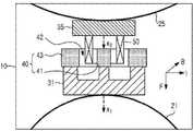
图1是示意地示出根据本发明第一实施例的振动马达的剖视图;1 is a sectional view schematically showing a vibration motor according to a first embodiment of the present invention;
图2是示出根据本发明第一实施例的第一振动器和第二振动器的自然共振频率的曲线图;2 is a graph showing natural resonance frequencies of a first vibrator and a second vibrator according to a first embodiment of the present invention;
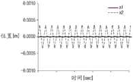
图3是示出根据本发明第一实施例的第一振动器和第二振动器在175hz的频带中的位移的曲线图;3 is a graph showing displacements of a first vibrator and a second vibrator in a frequency band of 175 Hz according to a first embodiment of the present invention;
图4是示出根据本发明第一实施例的第一振动器和第二振动器在300Hz的频带中的位移的曲线图;4 is a graph showing displacements of a first vibrator and a second vibrator in a frequency band of 300 Hz according to the first embodiment of the present invention;
图5是示意地示出根据本发明第二实施例的振动马达的剖视图;5 is a cross-sectional view schematically showing a vibration motor according to a second embodiment of the present invention;
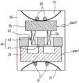
图6是示意地示出根据本发明第三实施例的振动马达的剖视图;6 is a cross-sectional view schematically showing a vibration motor according to a third embodiment of the present invention;
图7是示意地示出根据本发明第四实施例的振动马达的剖视图;7 is a cross-sectional view schematically showing a vibration motor according to a fourth embodiment of the present invention;
图8是示意地示出根据本发明第五实施例的振动马达的剖视图;8 is a sectional view schematically showing a vibration motor according to a fifth embodiment of the present invention;
图9是例示应用根据本发明的振动马达的移动式通信终端的结构的框图。FIG. 9 is a block diagram illustrating a structure of a mobile communication terminal to which a vibration motor according to the present invention is applied.
具体实施方式Detailed ways
以下,将参照附图描述本发明的优选实施例。在下面的说明中,描述诸如具体的部件之类的具体内容仅为提供本发明的全面理解,并且对本领域技术人员清楚的是可以进行不脱离本发明的范围的改变或修改。Hereinafter, preferred embodiments of the present invention will be described with reference to the accompanying drawings. In the following description, specific contents such as specific components are described only to provide a comprehensive understanding of the present invention, and it is clear to those skilled in the art that changes or modifications may be made without departing from the scope of the present invention.
图1是示意地示出根据本发明第一实施例的振动马达的剖视图。参照图1,根据本发明第一个实施例的振动马达包括外壳10、第一弹性构件21和第二弹性构件25、第一振动器31和第二振动器35、磁体40、以及线圈50。FIG. 1 is a sectional view schematically showing a vibration motor according to a first embodiment of the present invention. Referring to FIG. 1 , a vibration motor according to a first embodiment of the present invention includes a
外壳10提供容纳元件的空间。The
第一弹性构件21和第二弹性构件25可以是板弹簧,其末端被固定到外壳10上以使得以相反的方向施加弹力。例如,第一弹性构件21的末端被固定到外壳10的底部,并且第二弹性构件25的末端被固定到外壳的顶端。因此,第一弹性构件21向固定第二弹性构件25的外壳10的顶端施加弹力,而第二弹性件25向固定第一弹性构件21的外壳10的底部施加弹力。The first
优选地,第一弹性构件21和第二弹性构件25粘接或焊接到外壳10。Preferably, the first
第一振动器31和第二振动器35分别耦接到第一弹性构件21和第二弹性构件25的凸起部分。第一振动器31和第二振动器35以及第一弹性构件21和第二弹性构件25可以通过粘接构件彼此耦接,或者通过诸如铆钉之类的耦接构件彼此机械地耦接。The
磁体40附于第一振动器31的顶端以在第一振动器31所在的外围区域中产生磁场。优选地,磁体40向其中心均匀地分布磁通量。例如,磁体40可以包括第一圆柱形磁性构件41和第二环形磁性构件43,第二环形磁性构件43容纳第一磁性构件41并且与第一磁性构件41隔开预定距离。第一磁性构件41的顶端被磁化为N极,而第二磁性构件43的顶端被磁化为S极。A
在第二振动器35的一个表面(例如,底面)上设置线圈50并且线圈50位于由磁体40产生的磁场内。优选地,线圈50为环形并且被插入在第一磁性构件41和第二磁性构件43之间的环形空间中。The
此外,优选地,第一磁体41和第二磁体43以足够在其两者之间插入环形线圈50那么长的距离彼此间隔开。Furthermore, preferably, the
同时,如果将电流施加于处于由磁体40产生的磁场中的线圈50,并且磁场沿图1中示出的方向B,则电流将沿方向I流过线圈50。然后,沿方向F生成力,并且第一振动器31相应于生成的力沿方向F移动。此外,当交流电施加于线圈50时,第一振动器31由于基于以上所述机制的力以及由第一弹性构件21提供的弹力而向上和向下振动。此外,第二振动器35由于基于以上所述机制的力以及由第二弹性构件25提供的弹力而向上和向下振动。Meanwhile, if a current is applied to the
另外,第一振动器31和第二振动器35具有自然共振频率。第一振动器31和第二振动器35的响应仅在它们的自然谐振频率处是最大的,而在其余频率处很小。因此,根据本发明的第一个实施例的振动马达仅在两个共振频率处接收响应。In addition, the
第一振动器31的振动将相应于以下的数学式(1),并且第二振动器35的振动将相应于以下的数学式(2)。可以基于以下的数学式(3)和(4)不同地设置第一振动器31和第二振动器35的自然共振频率。The vibration of the
【数学式1】【Mathematical formula 1】
F0 sin w1t=M1x1″+c1x1′+k1x1F0 sin w1 t=M1 x1 ″+c1 x1 ′+k1 x1
【数学式2】【Mathematical formula 2】
F0 sin w2t=M2x2″+c2x2′+k2x2F0 sin w2 t=M2 x2 ″+c2 x2 ′+k2 x2
【数学式3】【Mathematical formula 3】
【数学式4】【Mathematical formula 4】
在数学式(1)到(4)中,M1和M2是第一振动器31和第二振动器35的各自的质量,c1和c2是阻尼系数,k1和k2分别是第一弹性构件21和第二弹性构件25的弹性系数,x1和x2指示图1中示出的位移,F0是由施加于线圈50的电流造成的激振力,并且w1和w2分别指示第一振动器31和第二振动器35的自然谐振频率。In the mathematical formulas (1) to (4), M1 and M2 are the respective masses of the
优选地,第一振动器31的自然谐振频率是100Hz到250Hz,并且第二振动器35的自然谐振频率是200Hz到450Hz。Preferably, the natural resonance frequency of the
参照图2,将第一振动器31的共振频率设置为大约175Hz,并且将第二振动器35的共振频率设置为大约300Hz。参照图3,可以看出第一振动器31仅在175Hz的频带中振动。参照图4,可以看出第二振动器35仅在300Hz的频带中振动。即,第一振动器31和第二振动器35的响应分别仅在共振频率处最大,同时另一方仅以小于共振方振动的-15db的水平振动。结果,第一振动器31和第二振动器35可以同时使用单个线圈50而振动,并且第一振动器31和第二振动器35的响应在它们各自的自然共振频率处最大。Referring to FIG. 2 , the resonance frequency of the
图5是示意地示出根据本发明第二实施例的振动马达的剖视图。参照图5,除了第二振动器35具有装在线圈的一个表面上的导榫(guide)37以外,根据本发明第二实施例的振动马达具有与根据本发明的第一实施例的振动马达相似的结构。导榫37为环形,并且导榫37的外径具有与线圈50的内径相应的尺寸。5 is a sectional view schematically showing a vibration motor according to a second embodiment of the present invention. Referring to Fig. 5, except that the
虽然在本发明的实施例中导榫37为环形,但是本发明不限于此。也就是说,当导榫37被固定到线圈50上时,导榫37充分地实现它的功能。例如,导榫37可以是附于线圈50的内表面的多个栅条。Although the
同时,如果在根据本发明实施例的振动马达中不同地设置阻尼特性,则有可能将响应特性控制在相同的共振频率。因此,本发明的振动马达通过振动马达的阻尼特性的调整提供不同的触觉反馈。本发明的第三实施例和第四实施例例示通过不同地设置阻尼特性而产生不同的触觉反馈的振动马达。Meanwhile, if the damping characteristics are set differently in the vibration motor according to the embodiment of the present invention, it is possible to control the response characteristics at the same resonance frequency. Therefore, the vibration motor of the present invention provides different tactile feedbacks through the adjustment of the damping characteristics of the vibration motor. The third and fourth embodiments of the present invention exemplify vibration motors that generate different haptic feedbacks by differently setting damping characteristics.
参照图6和图7,根据本发明第三实施例和第四实施例的振动马达具有与根据本发明第一实施例的振动马达相似的结构。然而,根据本发明第三实施例的振动马达通过不同地设置第一振动器31与外壳10的内壁之间的间隙以及第二振动器35与外壳10的内壁之间的间隙来调节第一振动器31和第二振动器35的阻尼特性。Referring to FIGS. 6 and 7 , vibration motors according to third and fourth embodiments of the present invention have a structure similar to that of the vibration motor according to the first embodiment of the present invention. However, the vibration motor according to the third embodiment of the present invention adjusts the first vibration by differently setting the gap between the
第一振动器31和外壳10的内壁之间的第一间隙(在图5A和图5B中标记为“gap1”)小于第二振动器35和外壳10的内壁之间的第二间隙(标记为“gap2”)。间隙gap1和gap2内部的空气妨碍第一振动器31和第二振动器35的移动,并且向第一振动器31和第二振动器35施加阻尼力。因此,相对强的阻尼力被施加于第一振动器31以提供给第一振动器31相对迅速的响应特性。The first gap between the
同时,根据本发明第四实施例的振动马达包括设置在第一弹性构件21和第二弹性构件上的各自具有不同的阻尼系数的磁流体61和磁流体65。磁流体61和磁流体65具有不同的阻尼系数,并且向第一振动器31和第二振动器35施加不同的阻尼力,从而实现不同的响应特性。例如,当设置在第一弹性构件21上的磁流体62具有比设置在第二弹性构件25上的磁流体65大的阻尼系数时,相对强的阻尼力被施加于第一振动器31,从而提供给第一振动器31相对迅速的响应特性。Meanwhile, the vibration motor according to the fourth embodiment of the present invention includes the
参照图8,根据本发明第五实施例的振动马达包括外壳10、第一弹性构件21和第二弹性构件25、第一振动器33和第二振动器39、磁体45、以及线圈50。第一弹性构件21和第二弹性构件25与根据本发明第一实施例的振动马达的第一弹性构件21和第二弹性构件25相同。Referring to FIG. 8 , a vibration motor according to a fifth embodiment of the present invention includes a
第一振动器33和第二振动器39与第一弹性构件21和第二弹性构件25的凸起部分耦接。优选地,第一振动器33和第二振动器39以及弹性构件21和弹性构件25通过粘接构件彼此耦接或者通过耦接构件机械地彼此耦接。The
磁体45附着于第一振动器33的顶端,并且在第一振动器33所处的外围区域中产生磁场。优选地,磁体45向其中心均匀地分布磁通量。优选地,磁体45为环形,并且第一磁性构件45的顶端被磁化为N极,而第一磁性构件45的底部被磁化为S极。The
线圈50为环形,其外径小于环形磁体45的内径。线圈50被固定到环形磁体45的内部形成的空间。外壳10包括线圈固定构件15,用于线圈50的附着。虽然图8中示出的实施例中线圈固定构件15为圆锥形,但是本发明不限于这样的形状。The
此外,调整第一振动器33的尺寸以允许向其耦接环形磁体45,并且第一振动器33优选地具有的形状是类板(plate-like)形状或具有环形凸起部的类板形状。In addition, the size of the
同时,第二振动器39具有小于线圈50的内径的外径,并且可以在线圈50内部的区域中自由地移动。特别地,第二振动器39作为铁心工作,并且当电流流过线圈50时,线圈50和第二振动器39作为电磁铁工作。不同于本发明的第一实施例,第一振动器35和第二振动器39不是由基于弗莱明定律的力驱动,而是由用作电磁铁的第二振动器39产生的磁场以及由磁体45产生的磁场的排斥力和吸引力驱动。Meanwhile, the
图9是例示应用根据本发明的振动马达的移动式通信终端的结构的框图。参照图9,该移动式通信终端包括显示模块133和外部输入接口135,显示模块133优选地使用液晶显示器或发光二极管(LED)显示器。FIG. 9 is a block diagram illustrating a structure of a mobile communication terminal to which a vibration motor according to the present invention is applied. Referring to FIG. 9, the mobile communication terminal includes a display module 133 and an
所述移动式通信终端还包括数字基带和应用处理器(DBAP)130。DBAP130处理输入,准备显示数据,并且运行软件程序(例如,操作系统程序和用户接口程序)。也就是说,由DBAP 130运行的软件程序基于移动式通信终端的功能通过显示模块133提供模式。DBAP 130使用从外部输入接口135输入的信号并且为用户提供逻辑以选择操作模式。例如,外部输入接口135可以是小键盘模块或触摸屏模块,用户通过该小键盘模块或触摸屏模块可以使用高频方面的变化、电阻或电压方面的变化、以及超声波方面的变化来检查接触位置以产生触摸区域的位置信息(例如,坐标)。The mobile communication terminal also includes a digital baseband and application processor (DBAP) 130 .
软件程序可以存储在DBAP 130内部的存储器中或者可以存储在与DBAP 130耦接的存储器141(例如,闪存)中。存储器141可以存储用户数据(例如,运动图像文件、声音文件、和电话号码)。DBAP 130还优选地连接到用于扩展模块(例如,智能数字卡)和外部接口(例如,USB接口)的端口。扩展模块143可以向系统添加附加功能(例如,通过将软件或数据存储在游戏、词典、或其他有用的特征模块中),并且外部接口145使得能够与另一系统交换程序和/或数据。The software programs may be stored in memory internal to DBAP 130 or may be stored in memory 141 (eg, flash memory) coupled to
DBAP 130连接到模拟基带控制器(ABC)110以与ABC 110交换数据或指令。ABC 110处理来自蜂窝式电话信号的数据或者用于蜂窝式电话信号的数据,产生用于驱动扬声器123的音频信号,并且对来自麦克风125的音频输入进行编码,以提供传统的便携电话功能。ABC 110优选地与基于蓝牙通信协议驱动的蓝牙模块113耦接,并且经由蓝牙模块113发送从DBAP 130发送的数据。
电池129与设备1354中的全部元件耦接以供给电源。电池129通常是可充电的,并且包括用于其充电操作的输入。The
ABC 110与RF收发器115耦接以双向地交换通过天线120接收的数据。RF收发器115、功率放大器117、开关119、和天线120是本领域技术人员了解的传统的蜂窝式电话机中包括的元件。
ABC 110还优选地与振动马达121耦接以基于从RF收发器115接收的信号或从DBAP 130接收的信号来控制振动马达121的操作。
例如,ABC 110通过天线120和RF收发器115接收呼叫请求信号或文本消息传输信号,并且控制振动马达121的操作以向用户通知信号的接收。具体地,ABC 110相应于移动式通信终端对呼叫请求信号的接收向振动马达121发送具有第一振动器可以振动的预置共振频率的交变电流,或者相应于文本消息传输信号的接收向振动马达121发送具有第二振动器可以振动的预置共振频率的电流。For example, the
如上所示,DBAP 130运行各种软件程序(例如,操作程序、用户界面程序和游戏程序),并且向用户提供不同的菜单或内容。用户选择并输入由移动式通信终端提供的菜单或内容。当用户接收菜单或内容中的一个时,DBAP 130向ABC 110发送相应于输入的信号。ABC 110优选地相应于从DBAP 130接收的信号来控制振动马达121的操作。例如,ABC 110可以向振动马达121发送具有第一振动器31或第二振动器35可以振动的预置共振频率的电流。此外,ABC 110可以重复地多次(例如,3次)向振动马达121发送具有第一振动器31或第二振动器35可以振动的预置共振频率的电流,或者可以以预定时段(例如,500ms)向振动马达121发送具有第一振动器31或第二振动器35可以振动的预置共振频率的电流。As shown above, the
在本发明的优选实施例中,虽然振动马达121由ABC 110控制,但是本发明不限于此,而是可以进行各种修改。In the preferred embodiment of the present invention, although the
在根据本发明的振动马达中,用户可以根据他或她的喜好来设置共振频率。此外,由于两个频率,可以通过振动的组合提供不同的触摸屏反馈。此外,因为两个共振频率是由一个致动器生成的,所以当振动马达被装在机体中时可以执行多种功能而不需任何额外的空间。In the vibration motor according to the present invention, the user can set the resonance frequency according to his or her preference. Also, thanks to the two frequencies, different touchscreen feedback can be provided through a combination of vibrations. In addition, since two resonance frequencies are generated by one actuator, the vibration motor can perform multiple functions without requiring any additional space when it is housed in the body.
虽然已经参照本发明的特定示范性实施例示出和描述本发明,但是本领域技术人员应该理解,可在形式和细节方面进行各种改变而不脱离由所附权利要求限定的本发明的精神和范围。While the invention has been shown and described with reference to certain exemplary embodiments thereof, it will be understood by those skilled in the art that various changes in form and details may be made without departing from the spirit and spirit of the invention as defined by the appended claims. scope.
Claims (10)
Applications Claiming Priority (3)
| Application Number | Priority Date | Filing Date | Title |
|---|---|---|---|
| KR1020080103494AKR101571562B1 (en) | 2008-10-22 | 2008-10-22 | Vibration motor |
| KR10-2008-0103494 | 2008-10-22 | ||
| PCT/KR2009/006093WO2010047529A2 (en) | 2008-10-22 | 2009-10-21 | Vibration motor |
Publications (2)
| Publication Number | Publication Date |
|---|---|
| CN102197571A CN102197571A (en) | 2011-09-21 |
| CN102197571Btrue CN102197571B (en) | 2014-06-11 |
Family
ID=42108092
Family Applications (1)
| Application Number | Title | Priority Date | Filing Date |
|---|---|---|---|
| CN200980141822.9AExpired - Fee RelatedCN102197571B (en) | 2008-10-22 | 2009-10-21 | Vibration motor |
Country Status (5)
| Country | Link |
|---|---|
| US (1) | US8242641B2 (en) |
| EP (1) | EP2338219B1 (en) |
| KR (1) | KR101571562B1 (en) |
| CN (1) | CN102197571B (en) |
| WO (1) | WO2010047529A2 (en) |
Families Citing this family (51)
| Publication number | Priority date | Publication date | Assignee | Title |
|---|---|---|---|---|
| EP1810185A4 (en)* | 2004-06-04 | 2010-01-06 | Therasense Inc | Diabetes care host-client architecture and data management system |
| US11203041B2 (en) | 2005-06-27 | 2021-12-21 | General Vibration Corporation | Haptic game controller with dual linear vibration actuators |
| WO2015006467A1 (en)* | 2013-07-09 | 2015-01-15 | Coactive Drive Corporation | Synchronized array of vibration actuators in an integrated module |
| US9459632B2 (en) | 2005-06-27 | 2016-10-04 | Coactive Drive Corporation | Synchronized array of vibration actuators in a network topology |
| US9764357B2 (en) | 2005-06-27 | 2017-09-19 | General Vibration Corporation | Synchronized array of vibration actuators in an integrated module |
| US8905624B1 (en) | 2009-08-20 | 2014-12-09 | Harold W. Howe | Control of vibratory/oscillatory mixers |
| US8487759B2 (en) | 2009-09-30 | 2013-07-16 | Apple Inc. | Self adapting haptic device |
| KR101122797B1 (en)* | 2010-04-26 | 2012-03-21 | 엘지이노텍 주식회사 | Linear vibrator having wideband |
| DE102010039981B4 (en)* | 2010-08-31 | 2023-02-02 | Robert Bosch Gmbh | Pressure supply unit for a fluid unit and fluid unit |
| JP5461381B2 (en)* | 2010-12-17 | 2014-04-02 | アルプス電気株式会社 | Vibration generator |
| KR20130015864A (en)* | 2011-08-05 | 2013-02-14 | 삼성전기주식회사 | Linear vibration device |
| CN102412695A (en)* | 2011-09-23 | 2012-04-11 | 北京航空航天大学 | Voice coil actuator based on linear elastic double-membrane spring structure |
| KR101869562B1 (en)* | 2011-12-27 | 2018-07-24 | 삼성전자주식회사 | Apparatus and method for gernerating vibration by using sound characteristics |
| KR20120068801A (en) | 2012-05-29 | 2012-06-27 | 나향옥 | Impactive vibration generator and applied apparatus thereof |
| US10967355B2 (en) | 2012-05-31 | 2021-04-06 | Resodyn Corporation | Continuous acoustic chemical microreactor |
| EP2864030B1 (en) | 2012-05-31 | 2019-11-13 | Resodyn Corporation | Mechanical system that fluidizes, mixes, coats, dries, combines, chemically reacts, and segregates materials |
| US9808778B2 (en) | 2012-05-31 | 2017-11-07 | Resodyn Corporation | Mechanical system that continuously processes a combination of materials |
| CN104350683B (en)* | 2012-06-08 | 2017-03-15 | 3M创新有限公司 | Modular communication device and system |
| JP2015070729A (en)* | 2013-09-30 | 2015-04-13 | 日本電産コパル株式会社 | Information terminal processing device and vibration generator system |
| CN105683865B (en) | 2013-09-30 | 2018-11-09 | 苹果公司 | Magnetic actuator for haptic response |
| US9317118B2 (en) | 2013-10-22 | 2016-04-19 | Apple Inc. | Touch surface for simulating materials |
| WO2015061448A2 (en)* | 2013-10-22 | 2015-04-30 | Resodyn Corporation | Mechanical resonant system |
| CN105814510B (en) | 2013-12-10 | 2019-06-07 | 苹果公司 | Band body attachment mechanism with haptic response |
| CN106489116B (en) | 2014-04-21 | 2019-08-16 | 苹果公司 | Distribution of forces for multi-touch input devices for electronic devices |
| WO2016036671A2 (en) | 2014-09-02 | 2016-03-10 | Apple Inc. | Haptic notifications |
| KR20170060114A (en) | 2014-09-24 | 2017-05-31 | 택션 테크놀로지 인코포레이티드 | Systems and methods for generating damped electromagnetically actuated planar motion for audio-frequency vibrations |
| US10353467B2 (en) | 2015-03-06 | 2019-07-16 | Apple Inc. | Calibration of haptic devices |
| AU2016100399B4 (en) | 2015-04-17 | 2017-02-02 | Apple Inc. | Contracting and elongating materials for providing input and output for an electronic device |
| WO2017044618A1 (en) | 2015-09-08 | 2017-03-16 | Apple Inc. | Linear actuators for use in electronic devices |
| US10573139B2 (en) | 2015-09-16 | 2020-02-25 | Taction Technology, Inc. | Tactile transducer with digital signal processing for improved fidelity |
| FR3042289B1 (en)* | 2015-10-13 | 2019-08-16 | Dav | TOUCH INTERFACE MODULE AND METHOD FOR GENERATING A HAPTIC RETURN |
| CN105305761B (en)* | 2015-10-27 | 2017-12-19 | 瑞声光电科技(常州)有限公司 | Vibrating motor |
| US10039080B2 (en) | 2016-03-04 | 2018-07-31 | Apple Inc. | Situationally-aware alerts |
| US10268272B2 (en)* | 2016-03-31 | 2019-04-23 | Apple Inc. | Dampening mechanical modes of a haptic actuator using a delay |
| JP6803685B2 (en)* | 2016-05-27 | 2020-12-23 | 日本電産コパル株式会社 | Vibration actuator |
| US10074469B2 (en) | 2016-06-06 | 2018-09-11 | Apple Inc. | Magnetic materials polarized at an oblique angle |
| CN106100277B (en)* | 2016-07-21 | 2018-10-16 | 瑞声科技(新加坡)有限公司 | Linear electric machine |
| CN106787589B (en)* | 2016-12-30 | 2020-07-21 | 脉创测控装备科技(苏州)有限公司 | Magnetic circuit structure based on magnetic fluid, vibration test equipment and vibration test method |
| CN110383216B (en)* | 2017-03-09 | 2023-09-08 | 贝洱海拉温控系统有限公司 | Electromagnetic actuator for a mechanical feedback unit |
| KR101972860B1 (en) | 2017-06-30 | 2019-04-26 | 주식회사 엠플러스 | Linear Vibrator. |
| US10622538B2 (en) | 2017-07-18 | 2020-04-14 | Apple Inc. | Techniques for providing a haptic output and sensing a haptic input using a piezoelectric body |
| US10835880B2 (en) | 2017-09-05 | 2020-11-17 | Resodyn Corporation | Continuous acoustic mixer |
| RU2672855C1 (en)* | 2018-02-19 | 2018-11-20 | Федеральное государственное бюджетное образовательное учреждение высшего образования "Петербургский государственный университет путей сообщения Императора Александра I" | Electric drive with vibrating motion |
| US10599223B1 (en) | 2018-09-28 | 2020-03-24 | Apple Inc. | Button providing force sensing and/or haptic output |
| US10691211B2 (en) | 2018-09-28 | 2020-06-23 | Apple Inc. | Button providing force sensing and/or haptic output |
| US20210067023A1 (en)* | 2019-08-30 | 2021-03-04 | Apple Inc. | Haptic actuator including shaft coupled field member and related methods |
| US11380470B2 (en) | 2019-09-24 | 2022-07-05 | Apple Inc. | Methods to control force in reluctance actuators based on flux related parameters |
| CN113411418B (en)* | 2020-03-16 | 2022-07-12 | 华为技术有限公司 | a mobile terminal |
| CN111817525B (en)* | 2020-07-31 | 2021-10-08 | 歌尔股份有限公司 | Excited vibration module and electronic terminal |
| US11977683B2 (en) | 2021-03-12 | 2024-05-07 | Apple Inc. | Modular systems configured to provide localized haptic feedback using inertial actuators |
| US11809631B2 (en) | 2021-09-21 | 2023-11-07 | Apple Inc. | Reluctance haptic engine for an electronic device |
Citations (3)
| Publication number | Priority date | Publication date | Assignee | Title |
|---|---|---|---|---|
| CN1227513A (en)* | 1996-06-21 | 1999-09-01 | 三洋电机株式会社 | Vibration generator for reporting and portable communication equipment using the same |
| US7038335B2 (en)* | 2004-06-23 | 2006-05-02 | Samsung Electro-Mechanics Co., Ltd. | Vertical vibrator |
| CN100998977A (en)* | 2006-01-10 | 2007-07-18 | 株式会社西铁城电子 | Vibrator |
Family Cites Families (7)
| Publication number | Priority date | Publication date | Assignee | Title |
|---|---|---|---|---|
| JP3748637B2 (en)* | 1996-10-14 | 2006-02-22 | 松下電器産業株式会社 | Vibration generator for portable devices |
| KR19980032013A (en) | 1995-12-15 | 1998-07-25 | 모리시타요오이찌 | Vibration generator |
| US6850138B1 (en)* | 1999-12-02 | 2005-02-01 | Nec Tokin Corporation | Vibration actuator having an elastic member between a suspension plate and a magnetic circuit device |
| JP2003009495A (en)* | 2001-06-20 | 2003-01-10 | Citizen Electronics Co Ltd | Oscillator and mounting structure thereof |
| JP2003033724A (en)* | 2001-07-23 | 2003-02-04 | Citizen Electronics Co Ltd | Electrical-mechanical oscillation converter and small- sized portable device with the same built-in |
| US7421088B2 (en) | 2003-08-28 | 2008-09-02 | Motorola, Inc. | Multifunction transducer |
| JP2006203709A (en)* | 2005-01-24 | 2006-08-03 | Citizen Electronics Co Ltd | Oscillator |
- 2008
- 2008-10-22KRKR1020080103494Apatent/KR101571562B1/ennot_activeExpired - Fee Related
- 2009
- 2009-10-21WOPCT/KR2009/006093patent/WO2010047529A2/ennot_activeCeased
- 2009-10-21CNCN200980141822.9Apatent/CN102197571B/ennot_activeExpired - Fee Related
- 2009-10-21EPEP09822205.2Apatent/EP2338219B1/ennot_activeNot-in-force
- 2009-10-22USUS12/603,885patent/US8242641B2/ennot_activeExpired - Fee Related
Patent Citations (3)
| Publication number | Priority date | Publication date | Assignee | Title |
|---|---|---|---|---|
| CN1227513A (en)* | 1996-06-21 | 1999-09-01 | 三洋电机株式会社 | Vibration generator for reporting and portable communication equipment using the same |
| US7038335B2 (en)* | 2004-06-23 | 2006-05-02 | Samsung Electro-Mechanics Co., Ltd. | Vertical vibrator |
| CN100998977A (en)* | 2006-01-10 | 2007-07-18 | 株式会社西铁城电子 | Vibrator |
Also Published As
| Publication number | Publication date |
|---|---|
| EP2338219B1 (en) | 2018-12-05 |
| KR20100044381A (en) | 2010-04-30 |
| KR101571562B1 (en) | 2015-11-25 |
| EP2338219A4 (en) | 2016-11-30 |
| EP2338219A2 (en) | 2011-06-29 |
| CN102197571A (en) | 2011-09-21 |
| US20100096936A1 (en) | 2010-04-22 |
| US8242641B2 (en) | 2012-08-14 |
| WO2010047529A3 (en) | 2010-07-29 |
| WO2010047529A2 (en) | 2010-04-29 |
Similar Documents
| Publication | Publication Date | Title |
|---|---|---|
| CN102197571B (en) | Vibration motor | |
| JP6978140B2 (en) | Vibration actuators and electronic devices | |
| JP7469688B2 (en) | Vibration actuator and electronic device | |
| CN106954147B (en) | Electronic device | |
| KR101250288B1 (en) | Haptic actuator | |
| JP2020036445A (en) | Vibration actuator and portable electronic device having the same | |
| CN104518632A (en) | Information terminal processing device and vibration generating device | |
| CN109905827B (en) | A vibration sounding device and mobile terminal | |
| CN104511416B (en) | Oscillation actuator | |
| CN113131707A (en) | Vibration actuator and electronic device | |
| CN106849593B (en) | More driving linear vibration motors and electronic equipment | |
| CN105340160A (en) | linear vibrator | |
| KR100804023B1 (en) | Vibration generator | |
| KR20130031528A (en) | Linear vibration motor | |
| KR200349093Y1 (en) | Multi-Function Device Type Micro Speaker To Generate vibration Using one fixed Coil and one Voice Coil | |
| WO2010029705A1 (en) | Mobile terminal device | |
| KR101198077B1 (en) | Linear vibration actuator | |
| KR20080043503A (en) | Vibration generator | |
| JP2006093774A (en) | Multi-function vibration actuator for stereo | |
| CN119278574A (en) | Vibration actuators and electronic devices | |
| CN110277891A (en) | a spring sounder |
Legal Events
| Date | Code | Title | Description |
|---|---|---|---|
| C06 | Publication | ||
| PB01 | Publication | ||
| C10 | Entry into substantive examination | ||
| SE01 | Entry into force of request for substantive examination | ||
| C14 | Grant of patent or utility model | ||
| GR01 | Patent grant | ||
| CF01 | Termination of patent right due to non-payment of annual fee | Granted publication date:20140611 Termination date:20191021 | |
| CF01 | Termination of patent right due to non-payment of annual fee |