CN102197294B - Conduit monitoring - Google Patents
Conduit monitoringDownload PDFInfo
- Publication number
- CN102197294B CN102197294BCN200980141853.4ACN200980141853ACN102197294BCN 102197294 BCN102197294 BCN 102197294BCN 200980141853 ACN200980141853 ACN 200980141853ACN 102197294 BCN102197294 BCN 102197294B
- Authority
- CN
- China
- Prior art keywords
- pipeline
- optical fiber
- sensing
- pipe
- aforementioned
- Prior art date
- Legal status (The legal status is an assumption and is not a legal conclusion. Google has not performed a legal analysis and makes no representation as to the accuracy of the status listed.)
- Active
Links
Images


Classifications
- G—PHYSICS
- G01—MEASURING; TESTING
- G01M—TESTING STATIC OR DYNAMIC BALANCE OF MACHINES OR STRUCTURES; TESTING OF STRUCTURES OR APPARATUS, NOT OTHERWISE PROVIDED FOR
- G01M3/00—Investigating fluid-tightness of structures
- G01M3/02—Investigating fluid-tightness of structures by using fluid or vacuum
- G01M3/04—Investigating fluid-tightness of structures by using fluid or vacuum by detecting the presence of fluid at the leakage point
- G01M3/24—Investigating fluid-tightness of structures by using fluid or vacuum by detecting the presence of fluid at the leakage point using infrasonic, sonic, or ultrasonic vibrations
- G01M3/243—Investigating fluid-tightness of structures by using fluid or vacuum by detecting the presence of fluid at the leakage point using infrasonic, sonic, or ultrasonic vibrations for pipes
- F—MECHANICAL ENGINEERING; LIGHTING; HEATING; WEAPONS; BLASTING
- F17—STORING OR DISTRIBUTING GASES OR LIQUIDS
- F17D—PIPE-LINE SYSTEMS; PIPE-LINES
- F17D5/00—Protection or supervision of installations
- F17D5/02—Preventing, monitoring, or locating loss
- F17D5/06—Preventing, monitoring, or locating loss using electric or acoustic means
- G—PHYSICS
- G01—MEASURING; TESTING
- G01D—MEASURING NOT SPECIALLY ADAPTED FOR A SPECIFIC VARIABLE; ARRANGEMENTS FOR MEASURING TWO OR MORE VARIABLES NOT COVERED IN A SINGLE OTHER SUBCLASS; TARIFF METERING APPARATUS; MEASURING OR TESTING NOT OTHERWISE PROVIDED FOR
- G01D5/00—Mechanical means for transferring the output of a sensing member; Means for converting the output of a sensing member to another variable where the form or nature of the sensing member does not constrain the means for converting; Transducers not specially adapted for a specific variable
- G01D5/48—Mechanical means for transferring the output of a sensing member; Means for converting the output of a sensing member to another variable where the form or nature of the sensing member does not constrain the means for converting; Transducers not specially adapted for a specific variable using wave or particle radiation means
- G—PHYSICS
- G01—MEASURING; TESTING
- G01H—MEASUREMENT OF MECHANICAL VIBRATIONS OR ULTRASONIC, SONIC OR INFRASONIC WAVES
- G01H9/00—Measuring mechanical vibrations or ultrasonic, sonic or infrasonic waves by using radiation-sensitive means, e.g. optical means
- G01H9/004—Measuring mechanical vibrations or ultrasonic, sonic or infrasonic waves by using radiation-sensitive means, e.g. optical means using fibre optic sensors
- G—PHYSICS
- G01—MEASURING; TESTING
- G01M—TESTING STATIC OR DYNAMIC BALANCE OF MACHINES OR STRUCTURES; TESTING OF STRUCTURES OR APPARATUS, NOT OTHERWISE PROVIDED FOR
- G01M3/00—Investigating fluid-tightness of structures
- G01M3/02—Investigating fluid-tightness of structures by using fluid or vacuum
- G01M3/04—Investigating fluid-tightness of structures by using fluid or vacuum by detecting the presence of fluid at the leakage point
- G01M3/042—Investigating fluid-tightness of structures by using fluid or vacuum by detecting the presence of fluid at the leakage point by using materials which expand, contract, disintegrate, or decompose in contact with a fluid
- G01M3/045—Investigating fluid-tightness of structures by using fluid or vacuum by detecting the presence of fluid at the leakage point by using materials which expand, contract, disintegrate, or decompose in contact with a fluid with electrical detection means
- G01M3/047—Investigating fluid-tightness of structures by using fluid or vacuum by detecting the presence of fluid at the leakage point by using materials which expand, contract, disintegrate, or decompose in contact with a fluid with electrical detection means with photo-electrical detection means, e.g. using optical fibres
- G—PHYSICS
- G01—MEASURING; TESTING
- G01P—MEASURING LINEAR OR ANGULAR SPEED, ACCELERATION, DECELERATION, OR SHOCK; INDICATING PRESENCE, ABSENCE, OR DIRECTION, OF MOVEMENT
- G01P3/00—Measuring linear or angular speed; Measuring differences of linear or angular speeds
- G01P3/02—Devices characterised by the use of mechanical means
- G01P3/14—Devices characterised by the use of mechanical means by exciting one or more mechanical resonance systems
Landscapes
- Physics & Mathematics (AREA)
- General Physics & Mathematics (AREA)
- Engineering & Computer Science (AREA)
- Acoustics & Sound (AREA)
- Mechanical Engineering (AREA)
- General Engineering & Computer Science (AREA)
- Investigating Or Analyzing Materials By The Use Of Ultrasonic Waves (AREA)
- Optical Transform (AREA)
- Examining Or Testing Airtightness (AREA)
- Pipeline Systems (AREA)
- Geophysics And Detection Of Objects (AREA)
- Testing Of Optical Devices Or Fibers (AREA)
- Cleaning In General (AREA)
- Measurement Of Mechanical Vibrations Or Ultrasonic Waves (AREA)
- Indicating Or Recording The Presence, Absence, Or Direction Of Movement (AREA)
- Measurement Of Velocity Or Position Using Acoustic Or Ultrasonic Waves (AREA)
Abstract
Description
Technical field
The present invention relates to pipe monitoring and inspection, and relate more specifically to underground utilities monitoring.
Background technology
Pipeline is the most economical feasible method of transporting fluid material (being oil and gas the most at large), but also has the pipeline of other types.Now, there are a large amount of pipeline basic facilities of being responsible for collection, transporting and send these natural resourcess, wherein only just have in the U.S. oil and the gas line that exceed 3/4ths gigameters.The continuous proper handling of these pipelines is vital, and fault is brought huge economic loss, environmental impact and also had potential calamitous physical damage.
Therefore, make sizable effort and monitored and checked pipeline.But the fact that the pipeline of a lot of pipeline networks of (sheer size) in large scale and a lot of kilometers is made up of underground or seabed installation (installation) makes effectively and monitoring efficiently becomes a difficult problem.
The most general pipeline inspection technology is to use intelligent pig (pig).Rabbit is advanced along pipeline, by the pressure-driven of the product betransporteding, and carries out the task such as clean pipeline walls, the profile of describing pipeline walls or inspection pipeline walls.Alternative monitoring technique comprises simply and advancing and satellite inspection along pipeline, and wherein pipe is addressable.Also use computing machine pipeline monitoring (CPM) system, the information such as pressure, temperature and flow velocity of on-site collection is for estimating the hydraulic pressure behavior of the product betransporteding thus.
Summary of the invention
The object of this invention is to provide improved pipe monitoring.
In first aspect, the invention provides a kind of method for monitoring fluid carrying pipeline, the method comprises: inquiry along the optical fiber (optic fibre) of the path orientation of described pipeline so that distributed acoustic sensing to be provided; Sound pulse is incorporated in pipeline; Each that measure in multiple discrete longitudinal sensing parts by distributed acoustic sensing is located the response to described sound pulse; And from described multiple measurements, derive pipeline situation profile (profile).
By this way, can the in the situation that causing minimum broken ring, stream obtain rapidly and easily situation profile pipeline basic facility and institute are comprised.By connecting suitable inquiry and treatment facility, can adopt the existing fiber moving along the path of pipe for sensing object.Quite the pipeline of vast scale will have along the optical fiber that is pre-existing in length of the path operation of pipeline.These typically the communications cable and/or for SCADA(supervisory control and data acquisition former for obvious logistics thereby pipeline that lay with pipeline simultaneously).In these cases, because existing cable can be made as a part that forms watch-dog, so only need the limited access of pipe just can monitor relatively long pipeline span.
In certain embodiments, sound pulse is incorporated in the fluid being included in pipe by Special pulse generator (impulser) or acoustic transducer.This typically may take the form of hydraulic top (hydraulic ram), but other equipment can be for inducing pressure wave in the fluid being carried by monitored pipeline.Pulse producer can for good and all be arranged in pipeline, or can be applied in existing valve station or contact place.Find, this pressure pulse can be with little decay by the pipeline very large distance of advancing, and therefore individual pulse source can be provided for monitoring 20,30 or enough inputs of 40km or longer pipeline.Pulse can be introduced in fluid in the normal operation period, and proper flow situation continues in pipeline simultaneously, causes for the little of policer operation or there is no the shut-down period.Introduce pulse with the interval of 10 seconds in one embodiment, and may adopt the interval between 5 seconds and 20 seconds.Typical monitoring period may be 10 minutes, but other cycles are also possible, and can adopt continuous monitoring.
Alternative as Special pulse generator, finds, the rabbit of advancing by pipeline can be arranged as and produce a series of pressure pulses.In the time that rabbit passes through the each circular weld in pipe, it runs into additional resistance and after rabbit, sets up overvoltage a little.In the time that rabbit passes through weld seam subsequently, discharge the pressure wave of advancing along pipe on both direction.The frequency of pulse depends on the spacing of weld seam and the speed of clearer.In this case, will understand, move gradually along pipe the position of impulse source, but this can not adversely affect method for supervising.In addition note, in pipe, form other constraint or unevenness when in time, for example, when hydrocarbon accumulation (build up) or mechanically deform, rabbit can generate higher acoustical signal.These can be identified by the part increase of searching in generated acoustical signal in the clearer process repeating in an embodiment.
The other of ducted sound or pressure pulse can the energy be unexpected cracking or leakage.The pressure pulse obtaining can be detected and for identify and/or locate this source and thus cracking or leak position.Therefore other aspect of the present invention provides a kind of method for monitoring fluid carrying pipeline, and the method comprises: inquiry along the optical fiber of the path orientation of described pipeline so that distributed acoustic sensing to be provided; Sound pulse is detected at each place in multiple discrete longitudinal sensing parts; And the source of definite described detection pulse.
The situation profile of pipe does not need to analyze clearly to determine corresponding physical characteristics (although this is possible).Can, by monitoring pipeline to obtain these profiles of one or more profiles and comparison to determine the variation in characteristic on a time cycle, derive more use.Thereby, can obtain two pipeline profiles on two dates of separating corresponding to thering is known time.Difference in profile can usage data analytical technology determine, to obtain having experienced information that physical change is relevant and the therefore position of these changes to which part of pipe.If accumulate in time the set of multiple profiles, can carry out the more complicated statistical study to profile, and will typically obtain at regular intervals profile for this purpose.In addition or alternatively, can before or after the maintenance of plan or maintenance job, obtain the known variant of profile with characterization pipeline.
Therefore can on the time interval, monitor the variation in pipe (and possibly the state of ground around pipe), and can provide to those and change relevant position and characterization information.This information can be pointed out other action, such as safeguarding, clean, physical examination or maintenance.
In certain embodiments, measure the amplitude response to sound pulse.This can carry out by the available bandwidth upper integral for each channel.But the other analysis of the data of returning from distributed sensing in certain embodiments allows to provide the spectral content of each channel, to realize the condition monitoring ability of enhancing.Distributed acoustic sensing sensing is in an embodiment of the present invention from the seismic signal in 0Hz-5kHz bandwidth (P pressure wave and S scissoring vibration ripple the two).But higher frequency is at large by strong attenuation, and monitor more at large the scope from 0Hz to 1kHz.
In various embodiment, can be positioned at pipe interior, be positioned at the outside surface of pipeline, be directly embedded in the place adjacent with pipeline or be positioned at the adjacent channel separating for the sensing optical fiber (fibre) of distributed sensing.For sensing optical fiber, there is not the position of regulation, as long as its position is to make it can detect the enough responses to sound pulse.Because possible high sensitivity in fiber optics (fibre optic) sensing, can measure with interfere measurement technique the phase differential of induction thus, for the potential scope of positioning optical waveguides or for selecting the scope of existing fiber very large.But generally speaking, preferably optical fiber is positioned at fluid bearings pipeline place or its about 3m, and is more preferably positioned at and treats the centerline of monitored pipeline or from its about 1.5m.
In a lot of embodiment, provide fiber optics distributed acoustic sensing by the light pulse inquiry optical fiber in order to different frequency.The optical fiber of single length single-mode fiber typically, and the preferably variation along its length without any catoptron, reverberator, grating or optical properties.This provides such advantage: can use the standard fiber of unmodified, basic continous length, require seldom or not amendment or preparation as for use.This embodiment typically determines that by detecting from Rayleigh (Rayleigh) back-scattered light of sensing optical fiber and with the frequency relation of interrogation pulse the acoustical signal inciding on optical fiber along fiber lengths operates.But, can adopt any suitable distributed sensing technology.For example, suitable DAS system is described in GB 2442745.
Because optical fiber does not have uncontinuity, so corresponding to the length of the fiber fragment of each channel with arrange and determine by the inquiry of optical fiber.These can be selected according to the physical layout of optical fiber, and also select according to the type of required monitoring.By this way, can be by the adjusting to the interrogator that changes input pulse width and input pulse dutycycle to optical fiber without any change, easily change along the distance of optical fiber and the length of each fiber fragment or channel resolution.In an embodiment, can provide the data from multiple channels substantially simultaneously.
The spatial resolution of distribution type fiber-optic optics sensing is less than or equal to 30m in a lot of embodiment, and is less than or equal in certain embodiments 20m or 10m.In certain embodiments, optical fiber is asked the data so that sensing to be provided in the distance that is more than or equal to 20km, and the distance that is more than or equal in other embodiments 30km or 40km is attainable.
Other aspect of the present invention provides pipeline watch-dog, and it comprises: optical fiber interrogator, is suitable for inquiring optical fiber and distributed fibre optic sensing is provided; Pulse producer, is suitable for producing pressure pulse in the fluid being included in pipeline; And processor, be suitable for receiving from described interrogator in response to described pressure pulse the data of sensing, and derive pipeline situation profile from the data of described sensing.
The present invention also provide a kind of for implement any method described herein and/or for embody the computer program of any apparatus characteristic described herein and computer program, with and on store for implementing any method described herein and/or for embodying the computer-readable medium of program of any apparatus characteristic described herein.
It is basic as herein with reference to the described method of accompanying drawing, equipment and/or purposes that the present invention extends to.
Any feature in one aspect of the invention can be with any suitable applied in any combination in other aspects of the present invention.Particularly, method aspect can be applied to equipment aspect, and vice versa.
And, generally can realize with software with hard-wired feature, and vice versa.Any quoting of software and hardware feature should correspondingly be explained herein.
Brief description of the drawings
With reference now to accompanying drawing,, will only preferred feature of the present invention be described by way of example, in the accompanying drawings:
Fig. 1 illustrates the basic element of character of distribution type fiber-optic optical sensor
Fig. 2 illustrates the Fibre Optical Sensor of arranging along the length of pipeline
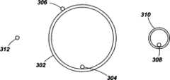
Fig. 3 is the xsect of pipeline and sensing optical fiber
Figure 4 and 5 illustrate the output of pipeline monitor data.
Embodiment
Fig. 1 illustrates the schematic diagram that distribution type fiber-optic optics sensing is arranged.The sensingoptical fiber 104 of one segment length is connected tointerrogator 106 at one end.Be sent to signalprocessor 108 and be sent to alternatively user interface from the output ofinterrogator 106, in fact this user interface can be realized by the PC suitably specifying.This sensing optical fiber can be a lot of kilometers in length, and it is long to be about in this example 40km.
Interrogator is launched the inquiry optical signalling that for example can comprise a series of pulses with selected frequency mode in sensing optical fiber.Certain a part of light that rayieigh backscatter phenomenon causes being input in optical fiber is reflected back to interrogator, and wherein it is detected so that the output signal that represents near acoustic jamming optical fiber to be provided.The form of optics input and the method for detection allow resolving into discrete sensing length on single jointed fiber space., can substantially be independent of at the sensing signal at adjacent lengths place and provide in the acoustical signal of one section of sensing length place sensing.Spatial resolution in this example is about 10m, causes the output of interrogator to take the form of 4000 independent data channels.
By this way, single sense optical fiber can provide the data of sensing, and this is similar to the multiplexed neighboring sensors array of arranging with linear path.
Fig. 2 illustrates and adopts the layout of the method according to this invention, sensing optical fiber 202(and the interrogator being associated and/orprocessor 204 thus) along the paths arrangement of pipeline 206.Pulseproducer 208 is arranged in some place along pipeline, and is suitable for introducing pressure pulse to the fluid inpipe.Pulse producer 208 can be taked various forms, but comprises in this example hydraulic top.The pressure pulse generating is advanced away from pulse producer on the both direction along pipe.Pipe is as waveguide, and found that this pulse can advance tens kilometers and exceedingly do not decayed.
In the time that the pipe of any length-specific is passed through in pulse, its produces can be distributed the acoustic jamming that formula FibreOptical Sensor 202 detects.Fig. 3 illustrates that the xsect ofpipe 302 and sensing optical fiber can detect the possible position of the impulse response in pipe.
Pipe in this example has the internal diameter of 1200mm and 50mm carbon steel wall, with about 80bar carrying rock gas.Pipe can be embedded in can be ground level or be about 1-2m under the surface of sea bed in some cases.Optical fiber 304 is positioned at the endoporus inside ofpipe 302, rests on the bottom of pipe.Optical fiber 306 joins the outside of pipe to, andoptical fiber 308 is arranged in thecable carrying pipeline 310 of separation, is positioned at the about 1.5m of center line from gas transmission line.Pipeline 310 is typically laid in the time that pipeline is installed with carrying communication and/or SCADA line.Optical fiber 312 is directly embedded in the ground on pipeline side, in from the about 1m of pipe center line.
To understand, place for each different optical fiber, the measurement response of the pressure pulse in pipe will be different and will depend on different factors.For example, the transmission characteristic on the ground betweenpipe 302 andpipeline 310 will be depended on by the signal ofoptical fiber 308 sensings, and sensingoptical fiber
Fig. 4 illustrates histogram and the waterfall figure being associated, and its explanation is in response to the distributed fiberoptic sensor output that is incorporated into a series of pressure pulses in adjacent lines.Data in Fig. 4 are produced by ducted sensing optical fiber.The x axle of histogram and waterfall figure is the length of sensing optical fiber, and this length is about 40km in this case.This histogram is illustrated in the amplitude of the sensing acoustical signal that the temporal a certain moment returns from sensing optical fiber.In order to check all 4000 channels, each representative in figure is from the peak amplitude of one group of 10m fragment.Can check if necessary each 10m.Figure below be contrast apart from discrete time illustrate sound intensity, renewal rate is the waterfall figure of 0.05 second, the time draws along the y axle of waterfall figure, nearest data are plotted in top.
Can find out two principal characters from waterfall figure.First be towards the constant zone of action of the sensing optical fiber corresponding to about 4000m length on this figure left side at 402 places.This is attributable to be positioned at commercial unit on this fiber fragment, that produce stable oscillation noise.Secondly, can in the region of the steady noise away fromcommercial unit 404, be clear that distinct V-arrangement (chevron) pattern.
The summit of each V-arrangement is positioned atpoint 406 places along optical fiber corresponding to the position of pulse producer.' V ' shape of this figure moves away from impulse source along pipe on both direction corresponding to pressure pulse, and the slope of ' V ' shape is corresponding to the acoustic velocity that is included in the pressurization gas in pipe, and it is about 400ms in this case-1.Can find out, a series of pressure pulses are introduced in gas, and form multiple tracks.On the histogram of top, in that moment, each pulse appears in its relevant position, separates along optical fiber.
But Fig. 5 illustrates the data to be rescaled similarly with the two axle of the similar form histogram of Fig. 4 and lower waterfall figure.In Fig. 5, the x axle of waterfall figure corresponding to the long sensing cable fragment of (relative with the 40km of Fig. 4) of about 4km and the renewal rate of Fig. 5 be set to 2 seconds (with 0.05 second of Fig. 4 relatively).
The data of Fig. 5 come from and pipe and fiber arrangement identical in Fig. 4, but obtain at pigging run duration, and in waterfall figure clearly the path of visible rabbit be diagonal line track 502.In the waterfall figure of Fig. 5, be also shown in a series of perpendicular line with various intensity.These lines are corresponding to the various positions of the length along pipe, and can be considered to fingerprint or the bar code of pipe, the pattern of line is corresponding to pipe and physical characteristics or the situation of its next-door neighbour's surrounding environment (being the ground that it is imbedded in this case) to a certain extent.
The situation profile being provided by this bar code effect is provided, will be understood, this V-arrangement effect corresponding to Fig. 4 is still checked with the time shaft of compression.The pressure pulse that passes through pipe can be considered to each part of the pipe of their processes of sound ' irradiation ', draw the response from pipe and environment thereof, and response is distributed the detection of formula sensing optical fiber thus.By averaging in time, can find out that some fragments of pipe have the impulse response different from other fragments.The possible cause of these differences is for example included in the variation near the ground composition weakness in local hydrocarbon accumulation, the tube wall on tube wall or the variation in wall profile or pipe.By this way, this figure provides the situation profile at the pipe on preset time or date.
Note, although the pressure pulse shown in Fig. 4 produced by Special pulse generator, as mentioned above, when rabbit during through each circular weld in pipe generation cause the pulse in Fig. 5 of situation profile of pipe.
Although not explanation, the spectral content of sense data can be extracted and provide.This will add extra dimension to the figure of Figure 4 and 5, and will realize the condition monitoring ability strengthening.Because upper frequency is by the altitude decay on ground, seismic signal is typically taking the frequency lower than 500Hz as main.
For example, by checking one or more selected frequency bands, can be filtered off from ' noise ' of the commercial plant (plant) in theregion 402 of Fig. 4.Pipe profile as above or bar code by frequency additional decomposition provide more details and allow more complicated analysis to user.For example, dissimilar physical phenomenon can be associated with special frequency band.For example, the variation in high frequency band may be indicated by the turbulent flow in the caused pipe of wax-like sedimental accumulation, and variation in lower band may be indicated the variation of the state of ground of laying therein pipe.Therefore the result of resolving can provide larger quantity and the information of good quality more to user.
To understand, only describe by way of example the present invention above, and can make within the scope of the invention the amendment of details.
In instructions and (depending on the circumstances) claim and accompanying drawing, disclosed each feature can be provided independently or with any appropriate combination.
Claims (10)
1. for monitoring a method for the fluid bearings pipeline that comprises pipeline, the method comprises:
Utilize optical signalling inquiry optical fiber, wherein said optical fiber is positioned to provide distributed acoustic sensing along the path of described pipeline;
Make rabbit through described pipeline, described rabbit produces sound pulse in the time that it moves through described pipeline in described pipeline;
The response of the described sound pulse that the rabbit by through described pipeline is produced is measured at each place in multiple discrete longitudinal sensing parts by distributed acoustic sensing; And
From described multiple measurements, derive pipeline situation profile.
2. method according to claim 1, comprises and derives one or more other conduit profile and described profile is compared to determine the variation in pipe characteristic.
3. method according to claim 2, comprises the lengthwise position of determining the variation in pipe characteristic.
4. according to the method described in aforementioned any one claim, wherein measure the amplitude of the response to described sound pulse.
5. according to the method described in aforementioned any one claim, wherein measure the spectral content of the response to described sound pulse.
6. according to the method described in aforementioned any one claim, wherein this distributed acoustic optical fiber is positioned at described pipe interior.
7. according to the method described in aforementioned any one claim, wherein this distributed acoustic optical fiber is adjacent with described pipeline.
8. according to the method described in aforementioned any one claim, the spatial resolution of wherein said distribution type fiber-optic optical sensor is less than or equal to 25m.
9. according to the method described in aforementioned any one claim, the length of wherein said distribution type fiber-optic optical sensor is more than or equal to 20km.
10. pipeline watch-dog, comprises:
Optical fiber interrogator, is suitable for utilizing optical signalling inquiry optical fiber and distributed acoustic sensing is provided; And
Processor, be suitable for receiving from described interrogator in response to the sound pulse of the rabbit generation by through pipeline the data of sensing, and derive pipeline situation profile from the data of described sensing, and described pipeline situation profile and the pipeline situation profile that had previously passed through at least one storage obtaining during pipeline at rabbit are compared to determine the variation of pipe characteristic.
Applications Claiming Priority (3)
| Application Number | Priority Date | Filing Date | Title |
|---|---|---|---|
| GB0815297.7 | 2008-08-21 | ||
| GBGB0815297.7AGB0815297D0 (en) | 2008-08-21 | 2008-08-21 | Conduit monitoring |
| PCT/GB2009/002058WO2010020796A1 (en) | 2008-08-21 | 2009-08-20 | Conduit monitoring |
Publications (2)
| Publication Number | Publication Date |
|---|---|
| CN102197294A CN102197294A (en) | 2011-09-21 |
| CN102197294Btrue CN102197294B (en) | 2014-06-11 |
Family
ID=39812396
Family Applications (3)
| Application Number | Title | Priority Date | Filing Date |
|---|---|---|---|
| CN200980141853.4AActiveCN102197294B (en) | 2008-08-21 | 2009-08-20 | Conduit monitoring |
| CN2009801418727AActiveCN102197287B (en) | 2008-08-21 | 2009-08-20 | Apparatus and method for tracking movement of objects in pipeline |
| CN200980141858.7AExpired - Fee RelatedCN102197284B (en) | 2008-08-21 | 2009-08-21 | fibre optic acoustic sensing |
Family Applications After (2)
| Application Number | Title | Priority Date | Filing Date |
|---|---|---|---|
| CN2009801418727AActiveCN102197287B (en) | 2008-08-21 | 2009-08-20 | Apparatus and method for tracking movement of objects in pipeline |
| CN200980141858.7AExpired - Fee RelatedCN102197284B (en) | 2008-08-21 | 2009-08-21 | fibre optic acoustic sensing |
Country Status (12)
| Country | Link |
|---|---|
| US (3) | US10900860B2 (en) |
| EP (3) | EP2326932B1 (en) |
| CN (3) | CN102197294B (en) |
| CA (3) | CA2734818C (en) |
| GB (1) | GB0815297D0 (en) |
| HU (1) | HUE043266T2 (en) |
| LT (1) | LT2326922T (en) |
| PL (1) | PL2326922T3 (en) |
| RU (3) | RU2511228C2 (en) |
| SI (1) | SI2326922T1 (en) |
| TR (1) | TR201903507T4 (en) |
| WO (3) | WO2010020796A1 (en) |
Families Citing this family (104)
| Publication number | Priority date | Publication date | Assignee | Title |
|---|---|---|---|---|
| GB2462096A (en)* | 2008-07-23 | 2010-01-27 | Schlumberger Holdings | Monitoring of a pipeline pig using external acoustic sensors |
| GB2478479B (en) | 2008-12-31 | 2013-06-19 | Shell Int Research | Method for monitoring deformation of well equipment |
| US20100200743A1 (en)* | 2009-02-09 | 2010-08-12 | Larry Dale Forster | Well collision avoidance using distributed acoustic sensing |
| CA2749540C (en) | 2009-02-09 | 2017-06-20 | Shell Internationale Research Maatschappij B.V. | Areal monitoring using distributed acoustic sensing |
| AU2010210332B2 (en) | 2009-02-09 | 2014-02-06 | Shell Internationale Research Maatschappij B.V. | Method of detecting fluid in-flows downhole |
| CN102597421B (en) | 2009-05-27 | 2016-03-30 | 光学感应器控股有限公司 | Fracturing monitoring |
| CA2763391C (en)* | 2009-05-27 | 2018-08-21 | Silixa Ltd | Method and apparatus for optical sensing |
| GB2476449B (en)* | 2009-09-18 | 2013-12-11 | Optasense Holdings Ltd | Wide area seismic detection |
| GB0919899D0 (en) | 2009-11-13 | 2009-12-30 | Qinetiq Ltd | Fibre optic distributed sensing |
| US8425683B2 (en)* | 2009-11-17 | 2013-04-23 | Acoustic Systems, Inc. | Method for tracking a scraper within a pipeline |
| US9109944B2 (en) | 2009-12-23 | 2015-08-18 | Shell Oil Company | Method and system for enhancing the spatial resolution of a fiber optical distributed acoustic sensing assembly |
| AU2010336498B2 (en) | 2009-12-23 | 2014-11-20 | Shell Internationale Research Maatschappij B.V. | Detecting broadside and directional acoustic signals with a fiber optical distributed acoustic sensing (DAS) assembly |
| US9388686B2 (en) | 2010-01-13 | 2016-07-12 | Halliburton Energy Services, Inc. | Maximizing hydrocarbon production while controlling phase behavior or precipitation of reservoir impairing liquids or solids |
| GB201008823D0 (en) | 2010-05-26 | 2010-07-14 | Fotech Solutions Ltd | Fluid flow monitor |
| US8605542B2 (en) | 2010-05-26 | 2013-12-10 | Schlumberger Technology Corporation | Detection of seismic signals using fiber optic distributed sensors |
| US8505625B2 (en) | 2010-06-16 | 2013-08-13 | Halliburton Energy Services, Inc. | Controlling well operations based on monitored parameters of cement health |
| WO2011163286A1 (en) | 2010-06-25 | 2011-12-29 | Shell Oil Company | Signal stacking in fiber optic distributed acoustic sensing |
| US8930143B2 (en) | 2010-07-14 | 2015-01-06 | Halliburton Energy Services, Inc. | Resolution enhancement for subterranean well distributed optical measurements |
| US8584519B2 (en) | 2010-07-19 | 2013-11-19 | Halliburton Energy Services, Inc. | Communication through an enclosure of a line |
| US20120020184A1 (en)* | 2010-07-26 | 2012-01-26 | Colin Wilson | Using a distributed optical acoustic sensor to position an object |
| GB201013712D0 (en)* | 2010-08-16 | 2010-09-29 | Qinetiq Ltd | Gunfire detection |
| GB201013704D0 (en) | 2010-08-16 | 2010-09-29 | Qinetiq Ltd | Border monitoring |
| EP2596387B1 (en) | 2010-09-01 | 2021-10-06 | Services Pétroliers Schlumberger | Distributed fiber optic sensor system with improved linearity |
| EP2656125A4 (en) | 2010-12-21 | 2018-01-03 | Shell Oil Company | System and method for making distributed measurements using fiber optic cable |
| EP2656112A2 (en) | 2010-12-21 | 2013-10-30 | Shell Internationale Research Maatschappij B.V. | Detecting the direction of acoustic signals with a fiber optical distributed acoustic sensing (das) assembly |
| GB201103479D0 (en) | 2011-03-01 | 2011-04-13 | Qinetiq Ltd | Conduit monitoring |
| CA2829092C (en) | 2011-03-09 | 2019-02-26 | Shell Internationale Research Maatschappij B.V. | Integrated fiber optic monitoring system for a wellsite and method of using same |
| GB201109372D0 (en)* | 2011-06-06 | 2011-07-20 | Silixa Ltd | Method for locating an acoustic source |
| US9347313B2 (en) | 2011-06-13 | 2016-05-24 | Shell Oil Company | Hydraulic fracture monitoring using active seismic sources with receivers in the treatment well |
| WO2012177547A1 (en) | 2011-06-20 | 2012-12-27 | Shell Oil Company | Fiber optic cable with increased directional sensitivity |
| GB201110403D0 (en)* | 2011-06-20 | 2011-08-03 | Qinetiq Ltd | Monitoring of conduits |
| GB201112154D0 (en) | 2011-07-15 | 2011-08-31 | Qinetiq Ltd | Seismic geophysical surveying |
| GB201112161D0 (en)* | 2011-07-15 | 2011-08-31 | Qinetiq Ltd | Portal monitoring |
| CN103733088B (en) | 2011-08-09 | 2016-07-06 | 国际壳牌研究有限公司 | Method and apparatus for measuring seismic parameters of a seismic vibrator |
| US9494461B2 (en) | 2011-12-15 | 2016-11-15 | Shell Oil Company | Detecting broadside acoustic signals with a fiber optical distrubuted acoustic sensing (DAS) assembly |
| GB201201727D0 (en)* | 2012-02-01 | 2012-03-14 | Qinetiq Ltd | Indicating locations |
| CN102588743B (en)* | 2012-03-08 | 2013-08-07 | 东北大学 | Device and method for real-time tracking and accurate positioning for internal detector in pipeline |
| GB2519009B (en) | 2012-08-01 | 2017-09-13 | Shell Int Research | Cable comprising twisted sinusoid for use in distributed sensing |
| US9823373B2 (en) | 2012-11-08 | 2017-11-21 | Halliburton Energy Services, Inc. | Acoustic telemetry with distributed acoustic sensing system |
| ITMI20122196A1 (en) | 2012-12-20 | 2014-06-21 | Eni Spa | METHOD AND SYSTEM FOR REMOTE DETECTION OF THE POSITION OF A PIG DEVICE INSIDE A PRESSURE CONDUCT |
| US10048395B2 (en)* | 2013-02-01 | 2018-08-14 | Westerngeco L.L.C. | Computing a gradient based on differences of plural pairs of particle motion sensors |
| US20140352442A1 (en)* | 2013-06-03 | 2014-12-04 | Macau University Of Science And Technology | Vibration Detection System Based on Biconical Tapered Fiber and the Method thereof |
| GB2515564A (en)* | 2013-06-28 | 2014-12-31 | Optasense Holdings Ltd | Improvements in fibre optic distributed sensing |
| WO2015109175A1 (en) | 2014-01-17 | 2015-07-23 | Westerngeco Llc | Seismic sensor coupling |
| US9535039B2 (en) | 2014-04-30 | 2017-01-03 | Control Devices, Inc. | Acoustic transmitter and method for underwater pipeline inspection gauges |
| EA028210B1 (en) | 2014-05-14 | 2017-10-31 | Эни С.П.А. | Method and system for the continuous remote monitoring of the position and advance speed of a pig device inside a pipeline |
| CA2947915A1 (en) | 2014-06-30 | 2016-01-07 | Exxonmobil Upstream Research Company | Pipeline constriction detection |
| BR112016029618A2 (en)* | 2014-07-18 | 2017-08-22 | Halliburton Energy Services Inc | Method and system for determining a location of an acoustic source outside a drillhole, and computer readable storage device. |
| US11988318B2 (en)* | 2015-07-07 | 2024-05-21 | Profound Positioning Inc. | Methods and systems to enhance pipeline trajectory reconstruction using pipeline junctions |
| AU2016297671B2 (en)* | 2015-07-17 | 2021-05-06 | The University Of Adelaide | Method and system for pipeline condition analysis |
| US10359302B2 (en) | 2015-12-18 | 2019-07-23 | Schlumberger Technology Corporation | Non-linear interactions with backscattered light |
| BR112018070565A2 (en) | 2016-04-07 | 2019-02-12 | Bp Exploration Operating Company Limited | downhole event detection using acoustic frequency domain characteristics |
| US11199084B2 (en) | 2016-04-07 | 2021-12-14 | Bp Exploration Operating Company Limited | Detecting downhole events using acoustic frequency domain features |
| CN106051379B (en)* | 2016-05-27 | 2018-01-16 | 沈阳鑫联石化设备有限公司 | A kind of wiper remote monitoring instrument and monitoring method |
| WO2018022012A1 (en)* | 2016-07-26 | 2018-02-01 | Halliburton Energy Services, Inc. | Electro acoustic technology (eat) for real time intelligent pigging |
| WO2018022063A1 (en)* | 2016-07-28 | 2018-02-01 | Halliburton Energy Services, Inc. | Real-time plug tracking with fiber optics |
| US10215341B2 (en)* | 2016-08-09 | 2019-02-26 | Baker Hughes, A Ge Company, Llc | Facilitating the transition between flooding and hydrotesting with the use of an intelligent pig |
| EP3608503B1 (en) | 2017-03-31 | 2022-05-04 | BP Exploration Operating Company Limited | Well and overburden monitoring using distributed acoustic sensors |
| CA3073623A1 (en) | 2017-08-23 | 2019-02-28 | Bp Exploration Operating Company Limited | Detecting downhole sand ingress locations |
| US11604127B2 (en)* | 2017-09-22 | 2023-03-14 | University Of Saskatchewan | Methods for detecting pipeline weakening |
| WO2019072899A2 (en) | 2017-10-11 | 2019-04-18 | Bp Exploration Operating Company Limited | Detecting events using acoustic frequency domain features |
| CN108053477B (en)* | 2017-12-20 | 2021-07-02 | 北京华航无线电测量研究所 | Numerical processing method for deformation in pipeline |
| WO2019126437A1 (en) | 2017-12-20 | 2019-06-27 | Kimberly-Clark Worldwide, Inc. | System for documenting product usage by recognizing an acoustic signature of a product |
| US11141327B2 (en) | 2017-12-20 | 2021-10-12 | Kimberly-Clark Worldwide, Inc. | System for intervening and improving the experience of the journey of an absorbent article change |
| EP3514564B1 (en)* | 2018-01-19 | 2023-05-31 | Centre National D'etudes Spatiales | Indoor positioning system |
| CN110107816A (en)* | 2018-02-01 | 2019-08-09 | 北京声创新技术发展有限责任公司 | Oil and gas pipeline pipe cleaner/detector infrasonic sound real-time tracking positioning system and method |
| US11181208B2 (en)* | 2018-05-24 | 2021-11-23 | Tdw Delaware, Inc. | Non-invasive pipeline pig signal using vibration sensors |
| US11132542B2 (en)* | 2018-06-28 | 2021-09-28 | Nec Corporation | Time-space de-noising for distributed sensors |
| CN109298080B (en)* | 2018-10-31 | 2023-12-15 | 江苏大学 | Time-sharing excitation system and method of special array sensor for weld defect detection based on characteristic guided wave |
| RU2726440C2 (en)* | 2018-11-26 | 2020-07-14 | Публичное акционерное общество "Транснефть" (ПАО "Транснефть") | Apparatus for determining location of cleaning device in pipeline |
| CN109306864A (en)* | 2018-11-27 | 2019-02-05 | 美钻深海能源科技研发(上海)有限公司 | Real-time monitoring device for underwater pig operation based on optical fiber detection |
| US11859488B2 (en) | 2018-11-29 | 2024-01-02 | Bp Exploration Operating Company Limited | DAS data processing to identify fluid inflow locations and fluid type |
| GB201820331D0 (en) | 2018-12-13 | 2019-01-30 | Bp Exploration Operating Co Ltd | Distributed acoustic sensing autocalibration |
| CN110375840A (en)* | 2019-06-25 | 2019-10-25 | 武汉理工光科股份有限公司 | Pig tracing localization method based on distributing optical fiber sensing |
| US12196074B2 (en) | 2019-09-20 | 2025-01-14 | Lytt Limited | Systems and methods for sand ingress prediction for subterranean wellbores |
| CA3154435C (en) | 2019-10-17 | 2023-03-28 | Lytt Limited | Inflow detection using dts features |
| EP4045766A1 (en) | 2019-10-17 | 2022-08-24 | Lytt Limited | Fluid inflow characterization using hybrid das/dts measurements |
| CN110822292A (en)* | 2019-10-29 | 2020-02-21 | 东莞新奥燃气有限公司 | System and method for monitoring running position of gas pipeline through ball |
| WO2021093974A1 (en) | 2019-11-15 | 2021-05-20 | Lytt Limited | Systems and methods for draw down improvements across wellbores |
| CN110987318B (en)* | 2019-12-11 | 2021-11-05 | 北京华展汇元信息技术有限公司 | Automatic detection device and detection method for gas leakage of high-pressure pipeline |
| WO2021118586A1 (en)* | 2019-12-13 | 2021-06-17 | Halliburton Energy Services, Inc. | Method and system to determine variations in a fluidic channel |
| US12188348B2 (en) | 2020-01-24 | 2025-01-07 | Lytt Limited | Detecting flow obstruction events within a flow line using acoustic frequency domain features |
| US11619542B2 (en)* | 2020-04-14 | 2023-04-04 | Nec Corporation | Distributed acoustic sensing based natural frequency measurement of civil infrastructures |
| US11543286B2 (en)* | 2020-04-14 | 2023-01-03 | Nec Corporation | Distributed acoustic sensing based acoustic wave speed scanning and mapping of civil infrastructures |
| WO2021249643A1 (en) | 2020-06-11 | 2021-12-16 | Lytt Limited | Systems and methods for subterranean fluid flow characterization |
| CA3182376A1 (en) | 2020-06-18 | 2021-12-23 | Cagri CERRAHOGLU | Event model training using in situ data |
| CA3204129A1 (en)* | 2020-08-10 | 2022-02-17 | Hifi Engineering Inc. | Methods and systems for tracking a pipeline inspection gauge |
| CN111965693B (en)* | 2020-08-21 | 2023-06-27 | 电子科技大学 | Pipeline trend tracing method and system based on optical cable |
| GB2611970B (en) | 2020-09-18 | 2025-04-09 | Halliburton Energy Services Inc | Non-intrusive tracking of objects and fluids in wellbores |
| US11674827B2 (en) | 2020-10-27 | 2023-06-13 | Nec Corporation | Saturation caused phase jump avoidance in DAS |
| EP3992600B1 (en) | 2020-11-02 | 2023-02-15 | Tata Consultancy Services Limited | Method and system for inspecting and detecting fluid in a pipeline |
| CN112504969B (en)* | 2021-02-03 | 2021-05-14 | 四川大学 | Device and method for pipeline flange weld health detection based on distributed acoustic sensing |
| RU2757682C1 (en)* | 2021-03-25 | 2021-10-20 | Федеральное государственное бюджетное образовательное учреждение высшего образования "Поволжский государственный университет телекоммуникаций и информатики" | Method for monitoring the condition of a viewing device on the route of a fiber-optic cable line |
| RU2758340C1 (en)* | 2021-04-13 | 2021-10-28 | Федеральное государственное бюджетное образовательное учреждение высшего образования "Поволжский государственный университет телекоммуникаций и информатики" | Method for non-destructive testing of optical fiber strength |
| CN113275341B (en)* | 2021-05-19 | 2022-04-08 | 精仪监测科技(苏州)有限公司 | Pipe cleaner tracking and positioning method based on distributed optical fiber vibration sensing |
| CN113447727B (en)* | 2021-06-30 | 2022-12-09 | 武汉理工光科股份有限公司 | Method and device for positioning lightning above oil and gas pipeline based on optical fiber vibration measurement system |
| US20230029221A1 (en)* | 2021-07-22 | 2023-01-26 | Nec Laboratories America, Inc | Galloping monitoring of overhead transmission lines using distributed fiber optic sensing |
| CN113933002B (en)* | 2021-08-12 | 2024-07-09 | 吉林大学 | Method for identifying leakage points of hydraulic test of long-distance large water delivery pressure pipeline |
| CN113883422B (en)* | 2021-09-10 | 2023-06-02 | 江苏禹治流域管理技术研究院有限公司 | Urban water supply network leakage on-line monitoring system |
| EP4202374A1 (en) | 2021-12-22 | 2023-06-28 | Universität Hamburg | Device for fibre-optical measurement and transport of measurement signals |
| CN114563074B (en)* | 2022-03-03 | 2024-06-18 | 西安热工研究院有限公司 | Vibration detecting system with high stability |
| US12359562B2 (en) | 2023-08-14 | 2025-07-15 | Saudi Arabian Oil Company | Traceable and disintegrable artificial intelligence powered sensing system and method for the detection of defects in pipelines |
| CN118731846B (en)* | 2024-06-13 | 2024-12-13 | 成都陆迪盛华科技有限公司 | Pipeline pig positioning method, system and medium based on distributed optical fiber |
| CN119406857A (en)* | 2024-11-12 | 2025-02-11 | 国家石油天然气管网集团有限公司 | A method and device for locating a pipe cleaner blockage |
Citations (1)
| Publication number | Priority date | Publication date | Assignee | Title |
|---|---|---|---|---|
| CN1942762A (en)* | 2004-04-15 | 2007-04-04 | Tdw特拉华有限公司 | ID-OD discrimination sensor concept for a magnetic flux leakage inspection tool |
Family Cites Families (45)
| Publication number | Priority date | Publication date | Assignee | Title |
|---|---|---|---|---|
| US3949353A (en)* | 1973-12-10 | 1976-04-06 | Continental Oil Company | Underground mine surveillance system |
| US4311391A (en)* | 1979-12-27 | 1982-01-19 | Westinghouse Electric Corp. | Passive fiber optic sonar system |
| US4313185A (en) | 1979-12-31 | 1982-01-26 | General Electric Company | Acoustic vibration sensor and sensing system |
| US4747309A (en)* | 1980-10-02 | 1988-05-31 | Imperial Chemical Industries Plc | Structures and methods of testing them with linear microphones |
| US4363114A (en) | 1981-01-21 | 1982-12-07 | The United States Of America As Represented By The Secretary Of The Navy | Low noise remote optical fiber sound detector |
| US4927232A (en)* | 1985-03-18 | 1990-05-22 | G2 Systems Corporation | Structural monitoring system using fiber optics |
| GB8307985D0 (en)* | 1983-03-23 | 1983-04-27 | British Gas Corp | Pipeline pig tracking |
| US4541278A (en)* | 1984-04-23 | 1985-09-17 | Union Oil Company Of California | Pipeline corrosion sensing device and method |
| EP0170736A1 (en)* | 1984-07-09 | 1986-02-12 | Amon, Glen C. | Pipeline fault status monitoring system |
| US4918303A (en)* | 1989-05-11 | 1990-04-17 | Conoco Inc. | Detecting disturbance with cross polarized fiber optic sensing |
| US5194847A (en)* | 1991-07-29 | 1993-03-16 | Texas A & M University System | Apparatus and method for fiber optic intrusion sensing |
| JP2833932B2 (en)* | 1992-06-18 | 1998-12-09 | 日本電気アイシーマイコンシステム株式会社 | Non-linear emphasis circuit |
| US5417112A (en)* | 1993-01-11 | 1995-05-23 | Tdw Delaware, Inc. | Apparatus for indicating the passage of a pig moving within an underground pipeline |
| GB9324333D0 (en)* | 1993-11-26 | 1994-01-12 | Sensor Dynamics Ltd | Measurement of one or more physical parameters |
| CN2212773Y (en)* | 1994-06-24 | 1995-11-15 | 刘达峰 | Pipeline obstacle detector device |
| US5549000A (en)* | 1994-06-27 | 1996-08-27 | Texaco, Inc. | Passive acoustic detection of pipeline pigs |
| JPH08233564A (en)* | 1995-02-28 | 1996-09-13 | Tokyo Gas Co Ltd | Pig running position detector |
| JPH08233932A (en)* | 1995-02-28 | 1996-09-13 | Tokyo Gas Co Ltd | Pig traveling position monitoring means |
| GB9520387D0 (en)* | 1995-10-06 | 1995-12-06 | R S T Projects Ltd | Debris monitoring system and apparatus |
| GB2362463B (en)* | 1997-05-02 | 2002-01-23 | Baker Hughes Inc | A system for determining an acoustic property of a subsurface formation |
| US6211964B1 (en)* | 1997-10-09 | 2001-04-03 | Geosensor Corporation | Method and structure for incorporating fiber optic acoustic sensors in a seismic array |
| GB9802688D0 (en)* | 1998-02-06 | 1998-07-29 | Marconi Gec Ltd | Improvements in or relating to sound detection |
| JP2000088561A (en)* | 1998-09-11 | 2000-03-31 | Tokyo Gas Co Ltd | Method for detecting running position of pig in conduit |
| AU2002246492A1 (en) | 2000-06-29 | 2002-07-30 | Paulo S. Tubel | Method and system for monitoring smart structures utilizing distributed optical sensors |
| CA2414385C (en)* | 2001-12-10 | 2007-03-13 | Moe Momayez | Remote structural material evaluation apparatus |
| US20040261547A1 (en)* | 2002-10-01 | 2004-12-30 | Russell David Alexander | Method of deriving data |
| CA2416171A1 (en) | 2003-01-13 | 2004-07-13 | Pure Technologies Ltd. | Pipeline monitoring system |
| US20050034917A1 (en)* | 2003-08-14 | 2005-02-17 | Baker Hughes Incorporated | Apparatus and method for acoustic position logging ahead-of-the-bit |
| GB0407982D0 (en) | 2004-04-08 | 2004-05-12 | Wood Group Logging Services In | "Methods of monitoring downhole conditions" |
| RU2271446C1 (en)* | 2004-07-27 | 2006-03-10 | Общество с ограниченной ответственностью "ПетроЛайт" | Vibroacoustic elongated object characteristics monitoring device |
| US7271884B2 (en)* | 2004-08-06 | 2007-09-18 | The United States Of America Represented By The Secretary Of The Navy | Natural fiber span reflectometer providing a virtual phase signal sensing array capability |
| CN2758749Y (en) | 2004-12-16 | 2006-02-15 | 何志强 | Alarm with signal sampling for natural gas pipeline cleaner |
| KR20060084256A (en) | 2005-01-19 | 2006-07-24 | 삼성전자주식회사 | Lens composition of light emitting diode device for liquid crystal display device, light emitting diode device, backlight unit and liquid crystal display device comprising the same |
| US7397976B2 (en)* | 2005-01-25 | 2008-07-08 | Vetco Gray Controls Limited | Fiber optic sensor and sensing system for hydrocarbon flow |
| RU2287131C1 (en)* | 2005-09-06 | 2006-11-10 | Общество с ограниченной ответственностью "ПетроЛайт" | Method for monitoring status of extensive objects, primarily, product lines, and device for realization of said method |
| GB2442745B (en)* | 2006-10-13 | 2011-04-06 | At & T Corp | Method and apparatus for acoustic sensing using multiple optical pulses |
| GB2442746B (en)* | 2006-10-13 | 2011-04-06 | At & T Corp | Method and apparatus for acoustic sensing using multiple optical pulses |
| DE102007004104A1 (en) | 2007-01-26 | 2008-07-31 | Ksb Aktiengesellschaft | Position detector for a part moved in a pipe |
| CN201034929Y (en)* | 2007-04-04 | 2008-03-12 | 南京旭飞光电有限公司 | Optical fiber gas sensors |
| RU68692U1 (en)* | 2007-07-05 | 2007-11-27 | Общество С Ограниченной Ответственностью "Проект-Ресурс" | PIPELINE MONITORING SYSTEM |
| CN101135577A (en)* | 2007-09-29 | 2008-03-05 | 中国科学院上海光学精密机械研究所 | Auto-tuning F-P fiber optic sensor |
| US7946341B2 (en)* | 2007-11-02 | 2011-05-24 | Schlumberger Technology Corporation | Systems and methods for distributed interferometric acoustic monitoring |
| CN101226078A (en)* | 2008-01-30 | 2008-07-23 | 广厦建设集团有限责任公司 | A detection method for abnormal vibration of long-distance linear structures based on distributed optical fiber sensors |
| GB2462096A (en)* | 2008-07-23 | 2010-01-27 | Schlumberger Holdings | Monitoring of a pipeline pig using external acoustic sensors |
| US8020616B2 (en)* | 2008-08-15 | 2011-09-20 | Schlumberger Technology Corporation | Determining a status in a wellbore based on acoustic events detected by an optical fiber mechanism |
- 2008
- 2008-08-21GBGBGB0815297.7Apatent/GB0815297D0/ennot_activeCeased
- 2009
- 2009-08-20HUHUE09784969Apatent/HUE043266T2/enunknown
- 2009-08-20RURU2011110518/28Apatent/RU2511228C2/enactive
- 2009-08-20LTLTEP09784969.9Tpatent/LT2326922T/enunknown
- 2009-08-20CNCN200980141853.4Apatent/CN102197294B/enactiveActive
- 2009-08-20USUS13/059,795patent/US10900860B2/enactiveActive
- 2009-08-20SISI200931949Tpatent/SI2326922T1/enunknown
- 2009-08-20PLPL09784969Tpatent/PL2326922T3/enunknown
- 2009-08-20WOPCT/GB2009/002058patent/WO2010020796A1/enactiveApplication Filing
- 2009-08-20TRTR2019/03507Tpatent/TR201903507T4/enunknown
- 2009-08-20WOPCT/GB2009/002032patent/WO2010020781A1/enactiveApplication Filing
- 2009-08-20CACA2734818Apatent/CA2734818C/enactiveActive
- 2009-08-20RURU2011110520/28Apatent/RU2515126C2/enactive
- 2009-08-20EPEP09784994.7Apatent/EP2326932B1/enactiveActive
- 2009-08-20CACA2734820Apatent/CA2734820C/enactiveActive
- 2009-08-20EPEP09784969.9Apatent/EP2326922B1/enactiveActive
- 2009-08-20CNCN2009801418727Apatent/CN102197287B/enactiveActive
- 2009-08-20USUS13/059,806patent/US8973444B2/enactiveActive
- 2009-08-21WOPCT/GB2009/002055patent/WO2010020795A1/enactiveApplication Filing
- 2009-08-21USUS13/059,810patent/US9625348B2/enactiveActive
- 2009-08-21CACA2734717Apatent/CA2734717C/enactiveActive
- 2009-08-21RURU2011110519/28Apatent/RU2518978C2/enactive
- 2009-08-21CNCN200980141858.7Apatent/CN102197284B/ennot_activeExpired - Fee Related
- 2009-08-21EPEP09784992.1Apatent/EP2318811B1/enactiveActive
Patent Citations (1)
| Publication number | Priority date | Publication date | Assignee | Title |
|---|---|---|---|---|
| CN1942762A (en)* | 2004-04-15 | 2007-04-04 | Tdw特拉华有限公司 | ID-OD discrimination sensor concept for a magnetic flux leakage inspection tool |
Also Published As
Similar Documents
| Publication | Publication Date | Title |
|---|---|---|
| CN102197294B (en) | Conduit monitoring | |
| EP2721387B1 (en) | Monitoring of conduits | |
| US12196635B2 (en) | Method and system for detecting dynamic strain | |
| US9594002B2 (en) | Conduit monitoring | |
| CN106662483A (en) | Detection of anomalies in rail wheelsets | |
| CN104246467A (en) | Monitoring transport network infrastructure | |
| CN108369118A (en) | Monitoring using fibre optical sensor to the fluid stream in open channel | |
| US12078528B2 (en) | Fiber sensing using supervisory path of submarine cables | |
| US20240302225A1 (en) | Automatic calibration for backscattering-based distributed temperature sensor | |
| Peng et al. | Method of precise sensing channel positioning forϕ-OTDR-based DAS | |
| JP2024521459A (en) | Identifying Internal Fibers in Deployed Fiber Cables Using Distributed Fiber Optic Sensing |
Legal Events
| Date | Code | Title | Description |
|---|---|---|---|
| C06 | Publication | ||
| PB01 | Publication | ||
| C10 | Entry into substantive examination | ||
| SE01 | Entry into force of request for substantive examination | ||
| ASS | Succession or assignment of patent right | Owner name:OPTICAL INDUCTOR HOLDINGS LTD. Free format text:FORMER OWNER: QINITIK CO., LTD. Effective date:20130216 | |
| C41 | Transfer of patent application or patent right or utility model | ||
| TA01 | Transfer of patent application right | Effective date of registration:20130216 Address after:England Hampshire Applicant after:OPTASENSE HOLDINGS LTD. Address before:London, England Applicant before:QINETIQ Ltd. | |
| C14 | Grant of patent or utility model | ||
| GR01 | Patent grant | ||
| CP03 | Change of name, title or address | ||
| CP03 | Change of name, title or address | Address after:surrey Patentee after:OPTASENSE HOLDINGS LTD. Country or region after:United Kingdom Address before:England Hampshire Patentee before:OPTASENSE HOLDINGS LTD. Country or region before:United Kingdom |