CN102190081B - Vision-based fixed point robust control method for airship - Google Patents
Vision-based fixed point robust control method for airshipDownload PDFInfo
- Publication number
- CN102190081B CN102190081BCN201010117161.0ACN201010117161ACN102190081BCN 102190081 BCN102190081 BCN 102190081BCN 201010117161 ACN201010117161 ACN 201010117161ACN 102190081 BCN102190081 BCN 102190081B
- Authority
- CN
- China
- Prior art keywords
- dirigible
- airship
- axle
- image
- point
- Prior art date
- Legal status (The legal status is an assumption and is not a legal conclusion. Google has not performed a legal analysis and makes no representation as to the accuracy of the status listed.)
- Expired - Fee Related
Links
Images


Landscapes
- Control Of Position, Course, Altitude, Or Attitude Of Moving Bodies (AREA)
Abstract
Translated fromChinese
Description
Translated fromChinese技术领域technical field
本发明属于飞艇飞行控制领域,特别是一种基于视觉的飞艇定点鲁棒控制方法。The invention belongs to the field of airship flight control, in particular to a vision-based fixed-point robust control method for an airship.
背景技术Background technique
目前,飞艇引起了人们的重视,并且被广泛应用于货运、广告、监测以及军事任务等各种不同的领域中。飞艇是一种可操纵的轻于空气的飞行器,依靠气囊封闭的轻质气体产生的浮力在空中浮起,并可以依靠发动机的动力在空中飞行。飞艇作为一种飞行器其最大的优势就是在于它具有无与伦比的滞空时间,其滞空时间可以天来计算。同时飞艇还可以悄无声息的在空中稳定飞行,这一特点在军事上也具有重要的应用。目前军用飞艇一般都使用氦气保持浮力,因此能安静并且平稳地完成升降和飞行,这对其携带现代化高科技监视与侦察设备来说至关重要。其次飞艇可以在其气囊中方便携带形状和尺寸几乎不受限制的大型雷达天线,对完成重要的军事侦察具有重要的作用。同时飞艇与飞机相比,军用飞艇可降低约30%左右的能耗和飞行费用,制造成本也很低,其雷达反射面积也要比现代飞机小许多。因而飞艇在现代军事发展中具有重要的地位。At present, airships have attracted people's attention and are widely used in various fields such as freight, advertising, surveillance, and military missions. An airship is a maneuverable aircraft that is lighter than air. It floats in the air by the buoyancy of the light gas enclosed by the air bag, and can fly in the air by the power of the engine. As a kind of aircraft, the biggest advantage of the airship is that it has an unparalleled time in the air, and its air time can be calculated in days. At the same time, the airship can also fly stably in the air quietly, which also has important military applications. At present, military airships generally use helium to maintain buoyancy, so they can complete lifting and flight quietly and smoothly, which is crucial for carrying modern high-tech surveillance and reconnaissance equipment. Secondly, the airship can conveniently carry a large radar antenna with almost unlimited shape and size in its airbag, which plays an important role in completing important military reconnaissance. Simultaneously, compared with airplanes, military airships can reduce energy consumption and flight costs by about 30%, and their manufacturing costs are also very low. Their radar reflection area is also much smaller than that of modern airplanes. Therefore, airships play an important role in modern military development.
另一方面,当今社会是一个人口密集、高度复杂的社会,人类的活动范围越来越大,面临的突发事件和异常事件越来越多,监控的重要性和难度也就越来越突出。飞艇作为一种新型监控手段,有其独特的优点,飞艇可以在一千多米高空,且其有效覆盖面积达20平方公里。同时可以利用其在目标地域上空悬停很长一段时间,使其上搭载的侦察仪器可以既精确又高效率的探测目标。结合我国的实际情况,我国有绵长的海岸线和陆地边境线,预警飞艇系统可用于为中空域内作战飞机提供情报和电子战支援,为地面防空系统提供早期预警。而在民用上,由于我国地广山多,许多地方自然灾害频繁发生,对人民的生命财产造成严重的威胁,因此在灾害发生前进行预测预防,在灾害发生后能第一时间掌握现场信息、开展迅速准确的救援十分必要。此时可以用无人飞艇低空遥感平台,一方面对环境信息进行监视采集为研究灾害的发生提供数据,另一方面能够及时监测灾害的发生,通过GPS定位系统,可准确探测出火源发生地,并且第一时间通知地面人员进行救援工作,而在城市中,无人飞艇可运用于城市交通监控、市政建设航拍、高空大气采样、城市火警监视等突发任务。特别的是,在国家开展重要性国际会议或展览时,若利用飞艇在空中监控,在其监控范围内,能及早预防突发事情的发生。因此,飞艇监控研究具有重大的意义。On the other hand, today's society is a densely populated and highly complex society. The scope of human activities is getting wider and wider, and there are more and more emergencies and abnormal events, so the importance and difficulty of monitoring are becoming more and more prominent. . As a new monitoring method, the airship has its unique advantages. The airship can be at an altitude of more than 1,000 meters, and its effective coverage area is up to 20 square kilometers. At the same time, it can be used to hover over the target area for a long time, so that the reconnaissance instruments on it can detect the target accurately and efficiently. Combined with the actual situation of our country, our country has a long coastline and land borders. The early warning airship system can be used to provide intelligence and electronic warfare support for combat aircraft in the medium airspace, and provide early warning for ground air defense systems. In terms of civilian use, due to the vast land and mountains in our country, natural disasters occur frequently in many places, which pose a serious threat to people's lives and property. It is necessary to carry out rapid and accurate rescue. At this time, the unmanned airship low-altitude remote sensing platform can be used. On the one hand, it can monitor and collect environmental information to provide data for the study of the occurrence of disasters. On the other hand, it can monitor the occurrence of disasters in time. Through the GPS positioning system, it can accurately detect the fire source. , and notify the ground personnel to carry out rescue work at the first time, and in the city, the unmanned airship can be used in urban traffic monitoring, municipal construction aerial photography, high-altitude atmospheric sampling, urban fire monitoring and other emergency tasks. In particular, if the airship is used to monitor in the air when the country is carrying out important international conferences or exhibitions, within the scope of its monitoring, emergencies can be prevented as early as possible. Therefore, research on airship monitoring is of great significance.
采用飞艇作为监控平台有很有优势。相比其他飞行器而言,飞艇的有效载荷更加大;能够垂直起降,对起飞跑道没有要求,能够在任何地方起飞;能够在空中悬停;起飞和回收容易;用户掌握和使用比较方便、可行。民用无人驾驶飞艇成本较低,易于推广应用。同时采用飞艇作为载体,在一定程度上能降低其飞行控制系统技术,能够降低成本。文献(飞行力学,26(5):28-31)采用变结构模型参考自适应控制方法设计了飞艇的定点控制器,但没有考虑到应用图像视觉实现智能自主定点控制。在飞艇监控过程中,飞艇的定点控制是一个关键问题,利用视觉图像设计高精度的飞艇定点控制技术具有重要的现实意义。摄像头可以用于现场监控,同时又可应用与控制,这就提出了基于视觉的飞艇定点控制问题。随着计算机视觉算法性能和可靠性的提高,非线性估计和识别技术的进步,计算机硬件技术的发展,以及完善的实时算法的应用,基于视觉的控制成为可能,并将成为研究的一个热点。Using an airship as a monitoring platform has great advantages. Compared with other aircraft, the payload of the airship is larger; it can take off and land vertically, there is no requirement for the take-off runway, and it can take off anywhere; it can hover in the air; it is easy to take off and recover; it is more convenient and feasible for users to grasp and use . The cost of civil unmanned airship is relatively low, and it is easy to popularize and apply. At the same time, using an airship as a carrier can reduce its flight control system technology and cost to a certain extent. Literature (Flight Mechanics, 26(5): 28-31) used the variable structure model reference adaptive control method to design the fixed-point controller of the airship, but did not consider the application of image vision to realize intelligent autonomous fixed-point control. In the airship monitoring process, the fixed-point control of the airship is a key issue, and it is of great practical significance to design a high-precision airship fixed-point control technology using visual images. The camera can be used for on-site monitoring, and can be applied and controlled at the same time, which raises the problem of fixed-point control of the airship based on vision. With the improvement of the performance and reliability of computer vision algorithms, the advancement of nonlinear estimation and recognition technology, the development of computer hardware technology, and the application of perfect real-time algorithms, vision-based control becomes possible and will become a research hotspot.
综上所述,基于视觉的飞艇定点控制技术是一个极其有价值的研究课题。其中需要解决的两个关键的问题是:一、飞艇位置和姿态的估计。二、控制器设计和图像和控制技术的结合。目前,国内外对位置和姿态的估计主要是针对无人机,我们可以参考无人机的位置和姿态估计算法来估计飞艇的位置和姿态。To sum up, vision-based airship fixed-point control technology is an extremely valuable research topic. The two key problems that need to be solved are: 1. Estimation of airship position and attitude. Second, the controller design and the combination of image and control technology. At present, the estimation of position and attitude at home and abroad is mainly for UAVs. We can refer to the position and attitude estimation algorithm of UAVs to estimate the position and attitude of airships.
(1)基于投影关系的方法(1) Method based on projection relationship
基于投影关系的方法通常要在飞艇定点视场内设置一个人工制作的监控图标,监控图标的尺寸以及在视场坐标系中的方向、位置参数一般都是已知的,从预先校准好的机载摄像机实时拍摄的图像中提取图标中某些特征元素的像面参数,利用投影前后的几何关系,首先求解出摄像机与监控图标的相对位置和姿态关系,然后经相应的坐标变换,将位姿关系转换到飞艇坐标系中,根据利用特征元素的不同,基于投影关系的方法又可以分为基于点信息的方法、基于平行线信息的方法、基于区域信息的方法和基于圆信息的方法。The method based on the projection relationship usually needs to set an artificial monitoring icon in the fixed-point field of view of the airship. The size of the monitoring icon and the direction and position parameters in the field of view coordinate system are generally known. Extract the image plane parameters of some characteristic elements in the icon from the real-time images captured by the camera, and use the geometric relationship before and after projection to first solve the relative position and attitude relationship between the camera and the monitoring icon, and then transform the pose The relationship is transformed into the airship coordinate system. According to the different feature elements used, the method based on the projection relationship can be divided into the method based on point information, the method based on parallel line information, the method based on area information and the method based on circle information.
(2)基于几何关系的方法(2) Method based on geometric relationship
基于几何关系的方法也使用定点图标,但并不通过图标上的特征元素的像面投影获取位姿参数,而是借助多种机载传感器的信息,通过简单的立体几何关系来求解。The method based on geometric relationship also uses fixed-point icons, but does not obtain the pose parameters through the image plane projection of the feature elements on the icons, but uses the information of various airborne sensors to solve them through simple three-dimensional geometric relationships.
(3)基于模式识别的方法(3) Method based on pattern recognition
飞艇位置和姿态的估计有时也可以理解为分类问题,从拍摄的场景图像中提取某些特征量,形成当前特定的一个模式,通过传统的模式识别方法或人工神经网络将此模式与某一预先定义好的标准模式对应起来,从而得出相应的位姿参数。而把图像加载入控制系统进行实时仿真,目前暂还没有相关研究。The estimation of the airship’s position and attitude can sometimes be understood as a classification problem. Some feature quantities are extracted from the captured scene images to form a current specific mode. This mode is compared with a certain pre-set pattern through traditional pattern recognition methods or artificial neural networks. The defined standard modes are matched to obtain the corresponding pose parameters. However, there is no relevant research on loading images into the control system for real-time simulation.
发明内容Contents of the invention
本发明的目的在于提供一种基于视觉的飞艇定点鲁棒控制方法,解决了基于视觉伺服的飞艇自主定点控制的两大难点:一是飞艇位置和姿态的估计算法的有效性和精确性;二是控制器设计以及图像和控制的结合。The object of the present invention is to provide a kind of robust control method of fixed-point airship based on vision, which solves two major difficulties of autonomous fixed-point control of airship based on visual servoing: one is the effectiveness and accuracy of the estimation algorithm of airship position and attitude; two is the combination of controller design and graphics and controls.
实现本发明目的的技术方案为:一种基于视觉的飞艇定点鲁棒控制方法,步骤如下:The technical scheme that realizes the object of the present invention is: a kind of airship fixed-point robust control method based on vision, the steps are as follows:
步骤一,定义地面坐标系、艇体坐标系、速度坐标系和图像坐标系,在此基础上确定机载摄像机安装方式;Step 1, define the ground coordinate system, hull coordinate system, speed coordinate system and image coordinate system, and determine the installation method of the airborne camera on this basis;
步骤二,根据射影几何学原理,提取飞艇的姿态角;Step 2, extract the attitude angle of the airship according to the principle of projective geometry;
步骤三,根据双目视觉视差原理,得到包含飞艇的姿态和位置的非线性方程组,把步骤二中得到的姿态角代入非线性方程组中,得到飞艇位置;
步骤四,采用Backstepping方法设计飞艇的鲁棒自适应定点控制方案,通过分析证明所提出的Backstepping控制方案能有效地保证闭环系统有界稳定,并把基于图像得到的姿态角和位置信息与控制相结合,实现闭环控制。
本发明与现有技术相比,其显著优点为:(1)给出了基于视觉的定点监控飞艇用的位置和姿态估计算法,同时基于Backstepping方法为飞艇设计定点飞行鲁棒控制,把通过位置和姿态估计算法提取的位置和姿态信息加载入飞艇定点控制技术中,实现了基于视觉的飞艇定点的控制。基于视觉的飞艇定点控制技术的原理是通过安装在飞艇上的摄像机,获取监控区域的图像,使用计算机视觉方法,估计出飞艇的飞行状态和相对位置,结合其他艇载传感器,实现飞艇的自主监视控制。(2)分析坐标系系统包括地面坐标系、艇体坐标系(摄像机坐标系)、速度坐标系和图像坐标系,在此基础上确定机载摄像机安装方式。为了确定是由俯仰角变化引起还是飞艇在(x,y,z)方向移动而引起的特征在图像中位置的变化,本发明采用双目CCD摄像机的特殊安装来解决此问题。(3)选用的H型作为监控图像特征,根据图像特征在图像中的位置和角度的变化来估算姿态角。基于图像估计出姿态角后,应用双目视觉视差原理得到飞艇的双目测量模型,飞艇的双目视差模型是关于飞艇位置和姿态的非线性模型,把姿态角代入非线性模型中,从而把非线性方程简化为线性方程,估计出位置。该方法提取出精确的俯仰角估计方案、得到了基于双目视觉视差原理的双目测量模型,把姿态和双目测量模型结合起来,把测量模型由非线性简化为线性,系统的计算量大大减少,且能提高系统的实时性。(4)图像和控制的结合采用Backstepping设计方法,该方法的优点在于:不要求非线性系统中的非线性必须满足增长性约束条件,仅要求系统的非线性能保证非线性系统转化为参数纯反馈的形式即可。同时反推设计方法使控制器设计过程系统化,结构化,且可以保证闭环系统的全局有界稳定性。所发展的基于视觉的飞艇定点控制技术可以指导基于视觉的直升机的定点飞行控制与基于视觉的自主机器人控制技术开发。Compared with the prior art, the present invention has the remarkable advantages as follows: (1) provides a position and attitude estimation algorithm based on the vision-based fixed-point monitoring airship, and simultaneously designs a robust control for the fixed-point flight of the airship based on the Backstepping method. The position and attitude information extracted by the algorithm and attitude estimation algorithm are loaded into the airship fixed-point control technology, and the vision-based airship fixed-point control is realized. The principle of vision-based airship fixed-point control technology is to obtain images of the monitoring area through the camera installed on the airship, use computer vision methods to estimate the flight status and relative position of the airship, and combine with other on-board sensors to realize autonomous monitoring of the airship control. (2) The analysis coordinate system includes the ground coordinate system, the hull coordinate system (camera coordinate system), the speed coordinate system and the image coordinate system, and on this basis, the installation method of the airborne camera is determined. In order to determine whether the change of the position of the feature in the image is caused by the change of the pitch angle or the movement of the airship in the (x, y, z) direction, the present invention uses a special installation of a binocular CCD camera to solve this problem. (3) The H type is selected as the monitoring image feature, and the attitude angle is estimated according to the position and angle change of the image feature in the image. After the attitude angle is estimated based on the image, the binocular measurement model of the airship is obtained by applying the principle of binocular visual parallax. The binocular parallax model of the airship is a nonlinear model about the position and attitude of the airship. The nonlinear equation reduces to a linear equation, which estimates the position. This method extracts an accurate pitch angle estimation scheme, and obtains a binocular measurement model based on the principle of binocular visual parallax. Combining the attitude and binocular measurement models, the measurement model is simplified from nonlinear to linear, and the calculation amount of the system is large. reduce and improve the real-time performance of the system. (4) The combination of image and control adopts the Backstepping design method. The advantage of this method is that it does not require that the nonlinearity in the nonlinear system must meet the growth constraints, and only requires the nonlinearity of the system to ensure that the nonlinear system can be transformed into a parameter-pure Feedback form is available. At the same time, the backstepping design method makes the controller design process systematic and structured, and can ensure the global bounded stability of the closed-loop system. The developed vision-based airship fixed-point control technology can guide the development of vision-based helicopter fixed-point flight control and vision-based autonomous robot control technology.
下面结合附图对本发明作进一步详细描述。The present invention will be described in further detail below in conjunction with the accompanying drawings.
附图说明Description of drawings
图1是飞艇控制总框图。Figure 1 is a general block diagram of the airship control.
图2是飞艇坐标系示意图。Figure 2 is a schematic diagram of the airship coordinate system.
图3(a)是安装双目摄像机的飞艇主视图;图3(b)是安装双目摄像机的飞艇右视图。Figure 3(a) is the front view of the airship with the binocular camera installed; Figure 3(b) is the right view of the airship with the binocular camera installed.
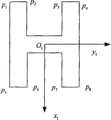
图4是本发明采用的特征图像。Fig. 4 is a feature image used in the present invention.
图5是飞艇俯仰角估计示意图。Fig. 5 is a schematic diagram of airship pitch angle estimation.
图6是飞艇偏航角估计示意图。Fig. 6 is a schematic diagram of airship yaw angle estimation.
图7是基于视觉的飞艇运动控制框图,其中(a)是偏航姿态控制系统图,(b)俯仰姿态控制系统图。Fig. 7 is a block diagram of vision-based airship motion control, in which (a) is a diagram of the yaw attitude control system, and (b) is a diagram of the pitch attitude control system.
图中的标号含义为:1、氦气囊,2、氦气囊闸阀,3、螺旋桨,4、升降舵,5、方向舵,6、位于飞艇Yc轴方向的摄像机,7、位于飞艇质心的摄像机,8、空气囊The meanings of the symbols in the figure are: 1, helium air bag, 2, gate valve of helium air bag, 3, propeller, 4, elevator, 5, rudder, 6, camera located in the direction of Yc axis of the airship, 7, camera located in the center of mass of the airship, 8 , air bag
具体实施方式Detailed ways
图1是飞艇的控制总框图,其系统分为艇载部分和地面控制站部分,具体的工作原理为:首先由艇载摄像机拍摄地面标志物的序列图像,通过艇载天线发射出去,由地面站接收设备接收,并传输到地面站控制计算机。地面计算机对其进行快速处理,获取标志物特征,通过这些特征完成飞艇姿态和位置的估计。然后由地面的发射天线将所得到的飞艇姿态和位置估计值发射出去,由飞艇上的接收设备接受,并传输到艇载计算机,由其完成估计值与艇载传感器所测得信号按比例组合的方式进行融合形成控制反馈信号,最后按Backstepping方法设计相应的控制器,达到对飞艇德鲁棒稳定控制。飞行控制系统是飞艇的核心部分,它在飞艇上的功能主要有两个:一是飞行控制,当飞艇在飞行的过程中受到外界环境的干扰时,能够做出实时的反应,保持飞艇的姿态和航迹不变,同时能够从地面站或艇载计算机中接受指令改变飞艇的飞行状态。二是飞行管理,能够进行导航计算和无线数据传输,在出现故障的情况下采取应急措施等等。Figure 1 is the overall control block diagram of the airship. Its system is divided into a ship-borne part and a ground control station part. The station receiving equipment receives and transmits to the ground station control computer. The ground computer quickly processes it to obtain the features of the markers, and completes the estimation of the attitude and position of the airship through these features. Then the airship's attitude and position estimates are transmitted by the transmitting antenna on the ground, received by the receiving equipment on the airship, and transmitted to the on-board computer, which completes the proportional combination of the estimated value and the signal measured by the on-board sensor The control feedback signal is formed by merging in the same way, and finally the corresponding controller is designed according to the Backstepping method to achieve the robust and stable control of the airship. The flight control system is the core part of the airship. It has two main functions on the airship: one is the flight control. When the airship is disturbed by the external environment during flight, it can respond in real time and maintain the attitude of the airship. The airship and track remain unchanged, and at the same time, it can accept instructions from the ground station or the on-board computer to change the flight status of the airship. The second is flight management, which can perform navigation calculations and wireless data transmission, and take emergency measures in the event of failures, etc.
本发明基于视觉的飞艇定点鲁棒控制方法实现第一个功能,利用视觉图像得到飞艇受干扰后的位姿信息,并设计控制器保持飞艇的姿态和位置不变,包括以下具体步骤:The vision-based airship fixed-point robust control method of the present invention realizes the first function, uses the visual image to obtain the pose information of the airship after being disturbed, and designs a controller to keep the attitude and position of the airship unchanged, including the following specific steps:
1、坐标系系统和机载摄像机安装方式的确定1. Determination of the coordinate system and the installation method of the airborne camera
图2是飞艇的坐标系系统,包括地面坐标系、艇体坐标系(摄像机坐标系)和速度坐标系。具体的坐标系定义如下:Fig. 2 is the coordinate system of the airship, including the ground coordinate system, the hull coordinate system (camera coordinate system) and the velocity coordinate system. The specific coordinate system is defined as follows:
(1)地面坐标系Sg-ogxgygzg(1) Ground coordinate system Sg -og xg yg zg
地面坐标系Sg-Ogxgygzg,在地面上选一点Og,使xg轴在水平面内并指向某一方向,zg轴垂直于地面并指向地心,yg轴也在水平面内并垂直于xg轴,其指向按照右手定则确定。本发明把地面坐标系设为惯性参考系简称惯性系。The ground coordinate system Sg -Og xg yg zg , select a point Og on the ground, make the xg axis in the horizontal plane and point to a certain direction, the zg axis is perpendicular to the ground and point to the center of the earth, and the yg axis Also in the horizontal plane and perpendicular to the xg axis, its pointing is determined by the right-hand rule. The present invention sets the ground coordinate system as the inertial reference system for short.
(2)艇体坐标系(摄像机坐标系)Sc-OcXcYcZc(2) Hull coordinate system (camera coordinate system) Sc -Oc Xc Yc Zc
原点O取在飞艇体积中心,坐标系与飞艇固连,Xc轴在飞艇对称平面内并平行于飞艇的设计轴线指向艇头,Yc轴垂直于飞艇的对称平面指向艇体右方,Zc轴在飞艇对称平面内,与Xc轴垂直并指向艇体下方。摄像机与飞艇固连,不另外取坐标系。The origin O is taken at the volume center of the airship, the coordinate system is fixedly connected with the airship, the Xc axis is in the symmetry plane of the airship and is parallel to the design axis of the airship and points to the bow, the Yc axis is perpendicular to the symmetry plane of the airship and points to the right of the hull, ZThe c- axis is in the plane of symmetry of the airship, perpendicular to the Xc- axis and pointing down the hull. The camera is fixedly connected to the airship and does not take another coordinate system.
(3)速度坐标系Sc-oxayaza(3) Velocity coordinate system Sc -oxa ya za
速度坐标系也称气流坐标系,原点o取在飞艇的体积中心,oxa轴与飞行速度向量V的方向一致,不一定在飞艇纵剖面内;oza轴在飞艇纵剖面内垂直于oxa轴指向艇腹部;oya轴垂直于xaoza平面指向右侧。The velocity coordinate system is also called the airflow coordinate system. The origin o is taken at the volume center of the airship, and the oxa axis is in the same direction as the flight velocity vector V, not necessarily in the airship longitudinal section; the oza axis is perpendicular to oxa in the airship longitudinal section The axis points to the midriff of the boat; the oya axis is perpendicular to the xa oza plane and points to the right.
(4)图像坐标系Oxy(4) Image coordinate system Oxy
图像坐标系(固联摄像头)位于图像平面内,原点O为光轴与图像平面的交点,x轴和y轴分别平行于Xc轴和Yc轴。The image coordinate system (fixed camera) is located in the image plane, the origin O is the intersection point of the optical axis and the image plane, and the x-axis and y-axis are parallel to the Xc- axis and Yc- axis respectively.
图3是飞艇的结构图,该飞艇包括氦气囊1,氦气囊闸阀2,螺旋桨3,升降舵4,方向舵5,空气囊8,位于飞艇y轴方向设置一个固连摄像机6,位于飞艇质心设置另一个悬挂摄像机7,该图包含双目摄像机的安装方案。双目视觉基本原理是从两个视点观察同一景物,以获取在不同视角下的感知图像,通过成像几何原理计算图像像素间的位置偏差,来获取景物的三维信息,这一过程与人类视觉的立体感知过程是类似的。本发明采用的双摄像机安装方案为:一个摄像头固定安装于飞艇的质心,其光心与艇体轴系z轴重合;另一个摄像头悬挂于飞艇的y轴上,其光心始终垂直地心,如图3所示。Fig. 3 is the structural diagram of airship, and this airship comprises helium air bag 1, helium air bag gate valve 2,
首先,在监控区域选取H型特征,假设其始终在成像平面。当飞艇在Xc轴位置或飞艇俯仰角发生改变时,特征在图像坐标系x方向位置也会改变,因此可以认为飞艇Xc轴位置和俯仰角与特征在图像坐标系x方向位置存在某种关系。因为只要飞艇的形状不发生改变,则飞艇的定点高度变化不大,所以由高度引起的特征位置变化忽略不计。而飞艇在机体坐标系Yc(即为艇体坐标系的y轴)方向的位置变化会只引起图像特征在图像坐标系y方向的位置变化,但是特征在图像坐标系x方向的位置变化,却有可能是由飞艇Xc轴位置变化或飞艇俯仰角变化而引起。为了区分出特征在图像坐标系x方向位置变化原因,本文采用悬挂式摄像机和固联式摄像机相结合的安装方案。假设悬挂式摄像头拍摄图片1,固联式摄像头拍摄图片2。首先将飞艇Xc轴位置变化和俯仰角变化引起的图像特征位置变化统一认为由俯仰引起,然后再解算由纯飞艇Xc轴位置变化引起的特征位置变化,结合二者就可以求得完全由俯仰运动引起的特征在图像位置的变化关系。其中飞艇运动变化对应的图像特征位置变化关系如表1所示。其中假设飞艇俯仰时头部指向+Xc方向。First, select the H-type feature in the monitoring area, assuming that it is always in the imaging plane. When the position of the airship on the Xc axis or the pitch angle of the airship changes, the position of the feature in the x direction of the image coordinate system will also change, so it can be considered that there is a certain relationship between the position of the Xc axis and the pitch angle of the airship and the position of the feature in the x direction of the image coordinate system relation. Because as long as the shape of the airship does not change, the height of the fixed point of the airship does not change much, so the change of the characteristic position caused by the height is negligible. However, the position change of the airship in the direction of the body coordinate system Yc (that is, the y-axis of the ship body coordinate system) will only cause the position change of the image feature in the y direction of the image coordinate system, but the position change of the feature in the image coordinate system x direction, However, it may be caused by the change of the position of the airship's Xc axis or the change of the pitch angle of the airship. In order to distinguish the reason for the position change of the feature in the x direction of the image coordinate system, this paper adopts the installation scheme of the combination of the suspended camera and the fixed camera. Assume that the hanging camera takes picture 1, and the fixed camera takes picture 2. Firstly, the change of the image feature position caused by the change of the position of the airship's Xc axis and the change of the pitch angle is considered to be caused by the pitch, and then the change of the feature position caused by the change of the pure airship's Xc axis position is solved. Combining the two, the complete Changes in image position of features caused by pitch motion. The relationship between the image feature position change corresponding to the airship motion change is shown in Table 1. It is assumed that the head of the airship points to the +Xc direction when pitching.
图4是研究本发明选取的H型图像特征,H型图像包含面积、矩、质心、主轴方向等各种丰富的信息,有利于飞艇的位姿估计。如图所示,在基准状态下,O1为特征中心,x1与y1分别平行于图像坐标系x轴与y轴,p1到p8为特征的边缘点。Fig. 4 is the H-type image feature selected for studying the present invention. The H-type image contains various rich information such as area, moment, center of mass, and main axis direction, which is beneficial to the pose estimation of the airship. As shown in the figure, in the reference state, O1 is the center of the feature, x1 and y1 are parallel to the x-axis and y-axis of the image coordinate system, respectively, and p1 to p8 are the edge points of the feature.
2、飞艇姿态估计2. Airship attitude estimation
图5是飞艇的俯仰角提取示意图,对于位于飞艇质心的摄像机(即固联式摄像机),假设基准状态即当飞艇平飞时,H特征中心水平线O1y1略低于像平面1的y轴,且距离为d,这是因为考虑了飞艇的平衡性,飞艇初始具有俯仰角α(一般说来,飞艇初始状态下α较小)。f是焦距,则有α=arctan(d/f)。当飞艇的俯仰角变为θ′时,像平面和O1y1的位置发生了改变,O1y1移动到O′1y′1,设O′1y′1与像平面2的y轴的距离为d′,则有Figure 5 is a schematic diagram of the pitch angle extraction of the airship. For the camera located at the center of mass of the airship (i.e., the fixed-mounted camera), it is assumed that the reference state is that when the airship is flying level, the horizontal line O1 y1 of the H feature center is slightly lower than the y of the image plane 1 axis, and the distance is d, this is because considering the balance of the airship, the airship initially has a pitch angle α (generally speaking, α is relatively small in the initial state of the airship). f is the focal length, then there is α=arctan(d/f). When the pitch angle of the airship changes to θ′, the positions of the image plane and O1 y1 have changed, O1 y1 moves to O′1 y′1 , let O′1 y′1 and the y of image plane 2 The distance of the axis is d′, then there is
θc=θ′-α=arctan(d′/f)-α (1)θc = θ'-α = arctan(d'/f)-α (1)
对于位于飞艇y轴方向的摄像机(即悬挂式摄像机),我们可以将飞艇Xc轴位置变化引起的特征位置的改变视为飞艇俯仰角所引起的特征位置的改变。设定飞艇平飞时的OcYc和O1y1重合。当飞艇Xc(即为艇体坐标系的x轴)轴位置变化时,图像中O1y1相距像平面的中心线的距离为d′l,则同理可到:For the camera located in the y-axis direction of the airship (that is, the suspended camera), we can regard the change of the characteristic position caused by the position change of the airship's Xc axis as the change of the characteristic position caused by the pitch angle of the airship. It is set that Oc Yc and O1 y1 coincide when the airship is in level flight. When the position of the airship Xc (that is, the x-axis of the hull coordinate system) changes, the distance between O1 y1 in the image and the center line of the image plane is d′l , and the same reason can be obtained:
θl=arctan(d′l/f) (2)θl = arctan(d′l /f) (2)
这里的θl是由于飞艇Xc轴位置的变化产生的等价俯仰角,θe是包含了飞艇Xc轴位置变化产生的等价俯仰角和飞艇本身的俯仰角。综上所述就可以得到飞艇的实际俯仰角Here, θl is the equivalent pitch angle due to the change of the position of the airship's Xc axis, and θe is the equivalent pitch angle generated by the change of the position of the airship's Xc axis and the pitch angle of the airship itself. In summary, the actual pitch angle of the airship can be obtained
θ=θe-θl (3)θ=θe -θl (3)
图6是飞艇的偏航角提取图。当飞艇发生偏航时,对应图像特征在图像坐标系中也会偏转一定角度。如图6所示,根据射影几何关系,H特征的左边缘线p1p5和图像坐标系x轴正方向的夹角即为偏航角,其中,O′p1与图像坐标系Oy平行,O′p1=d1,O′p5和图像坐标系Ox平行,O′p5=d2。这样就可以得到飞艇的偏航角Fig. 6 is an extraction diagram of the yaw angle of the airship. When the airship yaws, the corresponding image features will also deflect by a certain angle in the image coordinate system. As shown in Figure 6, according to the projective geometric relationship, the angle between the left edge line p1 p5 of the H feature and the positive direction of the x-axis of the image coordinate system is the yaw angle, where O′p1 is parallel to the image coordinate system Oy , O'p1 =d1 , O'p5 is parallel to the image coordinate system Ox, O'p5 =d2 . In this way, the yaw angle of the airship can be obtained
3、飞艇位置估计3. Airship position estimation
假设目标区域有已知点P,在地面坐标系中用坐标xg,yg,zg表示;它在两个图像平面(固连式摄像机图像平面为(Xc,Yc,Zc)称为c坐标,悬挂式摄像机图像平面为(XB,YB,ZB)称为b坐标)上的投影点分别为p1和p2,其图像坐标分别为(x1,y1)和(x2,y2)。P点在两个摄像机坐标系统的坐标分别为Xb,Yb,Zb和Xc,Yc,Zc。在两个摄像机坐标系统中,都采用小孔成像前投影模型,设两摄像机的焦距为f,光心距离为l,每个模型可得到两个透视投影公式:Assume that there is a knownpoint P in the target area, expressed by coordinates xg , yg , zg in the ground coordinate system; is called the c coordinate, and the projection points on the suspended camera image plane (XB , YB , ZB ) are called b coordinates) are p1 and p2 respectively, and their image coordinates are (x1 , y1 ) and (x2 , y2 ). The coordinates of point P in the two camera coordinate systems are Xb , Yb , Zb and Xc , Yc , Zc . In the two camera coordinate systems, the small hole imaging front projection model is used, the focal length of the two cameras is f, and the optical center distance is l, and two perspective projection formulas can be obtained for each model:
两个摄像机的空间变换关系为The spatial transformation relationship of the two cameras is

其中Rbc和Tbc分别为c坐标系到b坐标系的旋转矩阵和平移矩阵。Among them, Rbc and Tbc are the rotation matrix and translation matrix from the c coordinate system to the b coordinate system, respectively.
则两摄像机坐标系之间的关系是:Then the relationship between the two camera coordinate systems is:
令
则有then there is
联立(5)和(6)可得Combine (5) and (6) to get
从而得thus get
因为固联摄像机安装在飞艇的质心,所以P点相对于飞艇质心的坐标为(Xb,Yb,Zb),而P点在地面坐标系中的坐标为(xg,yg,zg)。假设Rib为飞艇质心b坐标空间到地面坐标空间的旋转变换矩阵,其可以表示Because the fixed camera is installed at the center of mass of the airship, the coordinates of point P relative to the center of mass of the airship are (Xb , Yb , Zb ), and the coordinates of point P in the ground coordinate system are (xg , yg , zg ). Suppose Rib is the rotation transformation matrix from the airship centroid b coordinate space to the ground coordinate space, which can be expressed as
则两向量之间存在如下关系:Then there is the following relationship between the two vectors:
上式ri(i=1,L,9)表示选择矩阵Rib中的各矩阵元素。取P点为地面坐标系的原点,则P坐标(xg,yg,zg)=(0,0,0)。如果在飞艇监控区域再选取已知点,每增加一个已知点,方程个数增加3个,但未知数并不增加,所以当监控区域上有4个已知点时,就可以解出飞艇的位置和姿态。根据双目视觉视差原理,得到飞艇的位姿模型,由于模型是非线性,求解困难。而把飞艇的姿态代入模型中,从而把非线性模型转换为线性方程,简化模型的求解。The above formula ri (i=1, L, 9) represents each matrix element in the selection matrix Rib . Taking point P as the origin of the ground coordinate system, then P coordinate (xg , yg , zg )=(0, 0, 0). If known points are selected in the airship monitoring area, the number of equations increases by 3 for each additional known point, but the number of unknowns does not increase, so when there are 4 known points in the monitoring area, the equation of the airship can be solved position and posture. According to the principle of binocular visual parallax, the pose model of the airship is obtained. Since the model is nonlinear, it is difficult to solve it. The attitude of the airship is substituted into the model, so that the nonlinear model is converted into a linear equation, and the solution of the model is simplified.
4、基于图像的鲁棒控制器设计4. Image-based robust controller design
图7是飞艇图像和控制结合的仿真框图,在Matlab仿真环境中把图像和控制器系统结合起来,真正做到基于视觉的飞艇定点控制。其中:在高度控制中,图像信息得到的高度和偏航角反馈回系统,水平面控制中,图像信息得到的位置信息x和y偏航角
本发明采用Backstepping(回归递推法)设计飞艇控制器。Backstepping设计方法的基本思想是将复杂的非线性系统分解成不超过系统阶数的子系统,然后为每个子系统分别设计Lyapunov函数和中间虚拟控制量,一直递推到得到整个系统的控制律,从而实现系统的全局调节或跟踪,使系统达到期望的性能指标。The present invention adopts Backstepping (regression recursion method) to design the airship controller. The basic idea of the Backstepping design method is to decompose the complex nonlinear system into subsystems that do not exceed the order of the system, and then design the Lyapunov function and the intermediate virtual control quantity for each subsystem, and deduce it until the control law of the entire system is obtained. In this way, the global adjustment or tracking of the system can be realized, so that the system can reach the desired performance index.
假设飞艇被控对象为Assuming that the controlled object of the airship is
其中x1为飞艇姿态角,x2为飞艇姿态角速度,x=[x1,x2]T,f(x)和b(x)代表飞艇的某一个通道的空气动力学动态,d(x,t)为时变的外部干扰,条件b(x)≠0可由飞艇的物理条件确定。外部干扰d(x,t)满足不等式|d(x,t)|≤ρ(x)υ,其中ρ(x)为光滑已知函数,υ为未知常数。Where x1 is the attitude angle of the airship, x2 is the angular velocity of the airship attitude, x=[x1 , x2 ]T , f(x) and b(x) represent the aerodynamic dynamics of a channel of the airship, d(x , t) is a time-varying external disturbance, and the condition b(x)≠0 can be determined by the physical conditions of the airship. The external disturbance d(x, t) satisfies the inequality |d(x, t)|≤ρ(x)υ, where ρ(x) is a smooth known function and υ is an unknown constant.
第1步:定义误差变量z1=x1-zd,其中zd为跟踪指令信号(定点监控中zd=0)且其2阶可导,则有:Step 1: Define the error variable z1 =x1 -zd , where zd is the tracking command signal (zd =0 in fixed-point monitoring) and its second-order derivability, then:
虚拟控制量设计为如下形式The virtual control quantity is designed as the following form
其中k1>0。where k1 >0.
定义另一个误差变量为Define another error variable as
z2=x2-α1 (13)z2 =x2 −α1 (13)
选取Lypunov函数为Choose the Lypunov function as
则but
将式(12)代入式(15)得Substitute formula (12) into formula (15) to get
第2步选取如下的Lyapunov函数Step 2 Select the following Lyapunov function
由于because
其中
考虑到(18),对V2*求导可得:Considering (18), deriving V2* gives:
设计如下形式的控制律:Design a control law of the form:
其中k2>0,
将控制律(20)代入到(19)可得:Substituting control law (20) into (19) can get:
令
选取参数自适应律为如下形式:The parameter adaptation law is selected as follows:
其中γ为大于零的设计常数。where γ is a design constant greater than zero.
为了分析参数估计误差的收敛性能,考虑如下形式的Lyapunov函数:In order to analyze the convergence performance of the parameter estimation error, consider the Lyapunov function of the following form:
考虑到(23),对V2求导可得:Considering (23), taking the derivative with respect to V2 gives:
考虑如下事实:Consider the following facts:
则(24)式可以变为Then (24) can be changed into
其中
通过控制律(20)的设计,使得闭环系统满足了条件(25),因此z1和z2渐近地收敛于初始条件的一个小的邻域内。Through the design of the control law (20), the closed-loop system satisfies the condition (25), so z1 and z2 asymptotically converge in a small neighborhood of the initial conditions.
本发明的关键之处在于图像和控制的结合,所发展的基于视觉的飞艇定点控制,由拍摄得到的序列图像,经常规的图像处理处理技术和所提出的位置与姿态估计算法,就可以得到控制所需要的反馈信息。利用函数软件实现Backstepping技术联合图像所得到的信息反馈形成闭环控制,其基于图像的水平面和纵向的飞行控制具体结构图如图7所示。偏航姿态控制系统作为飞行控制系统的一个子系统,其原理结构如图7(a)所示。其中T是螺旋桨推力,δr是方向舵偏向角。由双目视觉传感器和GPS等其它传感器相融合得到实际的偏航角,当实际输出的偏航角与给定值之间出现偏差时,控制器立即起作用,根据选用的控制律计算出输出的电信号的值,电信号作用于舵机和电动螺旋桨,舵机和电动螺旋桨来改变飞艇的飞行状态,修正这一偏差。当偏差趋于零后,控制器才停止作用。俯仰姿态控制系统作为整个飞行控制系统的一个子系统,其原理结构如图7(b)所示。其中δe是升降舵偏向角。其控制原理与偏航姿态控制系统相似,由双目视觉传感器和GPS等其它传感器相融合测得实际的俯仰角,当实际输出的俯仰角与给定值之间出现偏差时,控制器立即起作用,根据选用的控制律计算出输出的电信号的值,电信号作用于舵机,舵机的转动改变飞艇的飞行状态,修正这一偏差。当偏差趋于零后,控制器才停止作用。The key point of the present invention lies in the combination of image and control, the developed vision-based airship fixed-point control, the sequence images obtained by shooting, through the conventional image processing technology and the proposed position and attitude estimation algorithm, you can get Feedback required for control. The function software is used to realize the information feedback obtained by the Backstepping technology combined with the image to form a closed-loop control. The specific structure diagram of the image-based horizontal plane and vertical flight control is shown in Figure 7. The yaw attitude control system is a subsystem of the flight control system, and its principle structure is shown in Figure 7(a). where T is the propeller thrust andδr is the rudder deflection angle. The actual yaw angle is obtained by the fusion of the binocular vision sensor and other sensors such as GPS. When there is a deviation between the actual output yaw angle and the given value, the controller will take effect immediately and calculate the output according to the selected control law. The value of the electrical signal, the electrical signal acts on the steering gear and the electric propeller, and the steering gear and the electric propeller change the flight state of the airship to correct this deviation. When the deviation tends to zero, the controller stops functioning. The pitch attitude control system is a subsystem of the entire flight control system, and its principle structure is shown in Figure 7(b). where δe is the elevator deflection angle. Its control principle is similar to that of the yaw attitude control system. The actual pitch angle is measured by the fusion of binocular vision sensors and other sensors such as GPS. When there is a deviation between the actual output pitch angle and the given value, the controller immediately activates Function, calculate the value of the output electrical signal according to the selected control law, the electrical signal acts on the steering gear, the rotation of the steering gear changes the flight state of the airship, and corrects this deviation. When the deviation tends to zero, the controller stops functioning.
在基于图像的飞艇飞行控制中,首先将艇载摄像机所摄得的序列图像采用常规图像处理方法进行处理,并基于处理后的图像进行飞艇姿态和位置的估计。然后将所得到的飞艇姿态和位置估计值与艇载传感器所测得信号进行按线性比例组合的方式进行融合(如图像估计得到的俯仰角为θ1,而实际传感器测得的俯仰角为θ2,则通过线性比例组合的方式得到融合后的信号为θ=k1θ1+k2θ2,其中1≥k1≥0,1≥k2≥0,且有k1+k2=1),形成控制反馈信号,代入按Backstepping方法设计的鲁棒自适应定点控制方案(式(20)),进而达到鲁棒稳定控制。In image-based airship flight control, the sequence images captured by the on-board camera are processed by conventional image processing methods, and the attitude and position of the airship are estimated based on the processed images. Then, the airship attitude and position estimates obtained are fused with the signals measured by the on-board sensors in a linear proportional combination (for example, the pitch angle obtained by image estimation is θ1 , while the pitch angle measured by the actual sensor is θ2 , the fused signal obtained through linear proportional combination is θ=k1 θ1 +k2 θ2 , where 1≥k1 ≥0, 1≥k2 ≥0, and k1 +k2 = 1), form the control feedback signal, and substitute it into the robust adaptive fixed-point control scheme designed according to the Backstepping method (Formula (20)), and then achieve robust and stable control.
Claims (8)


Priority Applications (1)
| Application Number | Priority Date | Filing Date | Title |
|---|---|---|---|
| CN201010117161.0ACN102190081B (en) | 2010-03-04 | 2010-03-04 | Vision-based fixed point robust control method for airship |
Applications Claiming Priority (1)
| Application Number | Priority Date | Filing Date | Title |
|---|---|---|---|
| CN201010117161.0ACN102190081B (en) | 2010-03-04 | 2010-03-04 | Vision-based fixed point robust control method for airship |
Publications (2)
| Publication Number | Publication Date |
|---|---|
| CN102190081A CN102190081A (en) | 2011-09-21 |
| CN102190081Btrue CN102190081B (en) | 2013-09-04 |
Family
ID=44599165
Family Applications (1)
| Application Number | Title | Priority Date | Filing Date |
|---|---|---|---|
| CN201010117161.0AExpired - Fee RelatedCN102190081B (en) | 2010-03-04 | 2010-03-04 | Vision-based fixed point robust control method for airship |
Country Status (1)
| Country | Link |
|---|---|
| CN (1) | CN102190081B (en) |
Families Citing this family (12)
| Publication number | Priority date | Publication date | Assignee | Title |
|---|---|---|---|---|
| CN104006803B (en)* | 2014-06-20 | 2016-02-03 | 中国人民解放军国防科学技术大学 | The photographing measurement method of spin stabilization spacecraft rotational motion parameter |
| CN104168455B (en)* | 2014-08-08 | 2018-03-09 | 北京航天控制仪器研究所 | A kind of space base large scene camera system and method |
| CN104536448B (en)* | 2014-11-17 | 2017-02-22 | 哈尔滨工程大学 | Backstepping based control method for unmanned-plane attitude system |
| CN104656657B (en)* | 2014-12-30 | 2017-08-25 | 南京航空航天大学 | A kind of constant value air-dries and disturbs Stratospheric Airship in Position-Attitude control method |
| CN105180963B (en)* | 2015-07-22 | 2018-02-16 | 北京航空航天大学 | Unmanned plane telemetry parameter modification method based on online calibration |
| CN105957070B (en)* | 2016-04-26 | 2017-02-15 | 胡碧滢 | Small-sized unmanned plane camera orientation calibrating device and calibrating method |
| CN110673638B (en)* | 2019-10-15 | 2022-10-11 | 中国特种飞行器研究所 | Unmanned airship avoiding system and unmanned airship flight control system |
| CN110979669B (en)* | 2019-11-22 | 2021-06-01 | 武汉理工大学 | A variable saucer-shaped airship UAV |
| CN111308463B (en)* | 2020-01-20 | 2022-06-07 | 京东方科技集团股份有限公司 | Human body detection method and device, terminal equipment, storage medium and electronic equipment |
| CN113146174A (en)* | 2021-03-29 | 2021-07-23 | 湖南航天远望科技有限公司 | Rotary supporting module assembly, aerostat assembly tool and using method thereof |
| CN116700348B (en)* | 2023-07-12 | 2024-03-19 | 湖南文理学院 | Visual servo control method and system for four-rotor aircraft with limited vision |
| CN120009837B (en)* | 2025-01-10 | 2025-10-03 | 成都玖锦科技有限公司 | Target track simulation method, device and medium based on array antenna |
Citations (3)
| Publication number | Priority date | Publication date | Assignee | Title |
|---|---|---|---|---|
| CN1557676A (en)* | 2004-01-13 | 2004-12-29 | �Ϻ���ͨ��ѧ | Semi-autonomous flight control system and control method for unmanned airship |
| CN101441478A (en)* | 2008-12-26 | 2009-05-27 | 北京航空航天大学 | Small-sized unmanned aerial vehicle automatic landing leveling control method and apparatus |
| CN201364497Y (en)* | 2009-01-12 | 2009-12-16 | 甘灿新 | Remote-control far-distance monitoring and loading unmanned helicopter system |
Family Cites Families (2)
| Publication number | Priority date | Publication date | Assignee | Title |
|---|---|---|---|---|
| JPH10316095A (en)* | 1997-05-19 | 1998-12-02 | Dam Suigenchi Kankyo Seibi Center | Control system for unmanned remote navigation ship |
| US6811113B1 (en)* | 2000-03-10 | 2004-11-02 | Sky Calypso, Inc. | Internet linked environmental data collection system and method |
- 2010
- 2010-03-04CNCN201010117161.0Apatent/CN102190081B/ennot_activeExpired - Fee Related
Patent Citations (3)
| Publication number | Priority date | Publication date | Assignee | Title |
|---|---|---|---|---|
| CN1557676A (en)* | 2004-01-13 | 2004-12-29 | �Ϻ���ͨ��ѧ | Semi-autonomous flight control system and control method for unmanned airship |
| CN101441478A (en)* | 2008-12-26 | 2009-05-27 | 北京航空航天大学 | Small-sized unmanned aerial vehicle automatic landing leveling control method and apparatus |
| CN201364497Y (en)* | 2009-01-12 | 2009-12-16 | 甘灿新 | Remote-control far-distance monitoring and loading unmanned helicopter system |
Non-Patent Citations (2)
| Title |
|---|
| 王景峰,田立新.具有制动动力学的Mkdv-Burgers"方程的backstepping边界控制.《江苏大学学报》.2006,第27卷(第1期),87-90.* |
| 蒋鸿翔,徐锦法,高正.新型无人直升机的视觉导引控制与仿真.《信息与控制》.2009,第38卷(第3期),297-299.* |
Also Published As
| Publication number | Publication date |
|---|---|
| CN102190081A (en) | 2011-09-21 |
Similar Documents
| Publication | Publication Date | Title |
|---|---|---|
| CN102190081B (en) | Vision-based fixed point robust control method for airship | |
| CN107014380B (en) | Combined Navigation Method of Visual Navigation and Inertial Navigation Based on Aircraft | |
| CN105353772B (en) | A kind of Visual servoing control method in UAV Maneuver target locating | |
| CN103365297B (en) | Based on four rotor wing unmanned aerial vehicle flight control methods of light stream | |
| CN104062977B (en) | Full-autonomous flight control method for quadrotor unmanned aerial vehicle based on vision SLAM | |
| CN105022401B (en) | Vision-based collaborative SLAM method for multi-quadrotor UAVs | |
| CN108563242B (en) | A kind of air-sea, which independently cooperates with, searches and rescues M3U platform | |
| CN104102218B (en) | The perception of view-based access control model servo and bypassing method and system | |
| CN110333735B (en) | A system and method for realizing secondary positioning of unmanned aerial vehicle in water and land | |
| CN109901580A (en) | A cooperative path and obstacle avoidance system and method for unmanned aerial vehicle and unmanned ground robot | |
| CN110347186B (en) | An autonomous tracking system for ground moving targets based on bionic binocular linkage | |
| CN112789672A (en) | Control and navigation system, attitude optimization, mapping and positioning technology | |
| CN108062108A (en) | A kind of intelligent multi-rotor unmanned aerial vehicle and its implementation based on airborne computer | |
| CN106647790A (en) | Four-rotor unmanned aerial vehicle aircraft system oriented to complex environment and flying method | |
| CN104118555B (en) | A kind of unmanned control and the method for building up of flight control system thereof | |
| CN104932529A (en) | Unmanned plane autonomous flight cloud control system | |
| CN201217501Y (en) | Suspending type aviation camera shooting self-determination aircraft system | |
| CN105793792A (en) | Flight auxiliary method and system of unmanned aerial vehicle, unmanned aerial vehicle, and mobile terminal | |
| CN107144281A (en) | Unmanned plane indoor locating system and localization method based on cooperative target and monocular vision | |
| CN115933718B (en) | A UAV autonomous flight technology method integrating panoramic SLAM and target recognition | |
| CN113920186B (en) | Low-altitude unmanned-machine multi-source fusion positioning method | |
| CN113063401A (en) | Unmanned aerial vehicle aerial survey system | |
| US12397938B2 (en) | Aerial vehicle path determination | |
| CN114518107B (en) | A wireless synchronous control system based on UAV remote control source | |
| CN112859923B (en) | A UAV visual formation flight control system |
Legal Events
| Date | Code | Title | Description |
|---|---|---|---|
| C06 | Publication | ||
| PB01 | Publication | ||
| C10 | Entry into substantive examination | ||
| SE01 | Entry into force of request for substantive examination | ||
| C14 | Grant of patent or utility model | ||
| GR01 | Patent grant | ||
| CF01 | Termination of patent right due to non-payment of annual fee | Granted publication date:20130904 Termination date:20190304 | |
| CF01 | Termination of patent right due to non-payment of annual fee |