CN102178557B - Pelvic internal fixation unit and application thereof - Google Patents
Pelvic internal fixation unit and application thereofDownload PDFInfo
- Publication number
- CN102178557B CN102178557BCN 201110122458CN201110122458ACN102178557BCN 102178557 BCN102178557 BCN 102178557BCN 201110122458CN201110122458CN 201110122458CN 201110122458 ACN201110122458 ACN 201110122458ACN 102178557 BCN102178557 BCN 102178557B
- Authority
- CN
- China
- Prior art keywords
- pelvis
- internal
- pelvic
- screw
- fixator
- Prior art date
- Legal status (The legal status is an assumption and is not a legal conclusion. Google has not performed a legal analysis and makes no representation as to the accuracy of the status listed.)
- Expired - Fee Related
Links
- 210000004197pelvisAnatomy0.000claimsabstractdescription33
- 206010034246Pelvic fracturesDiseases0.000claimsabstractdescription16
- 208000014674injuryDiseases0.000abstractdescription8
- 208000010392Bone FracturesDiseases0.000abstractdescription7
- 206010017076FractureDiseases0.000abstractdescription7
- 238000000034methodMethods0.000abstractdescription5
- 238000001356surgical procedureMethods0.000abstractdescription5
- 230000000399orthopedic effectEffects0.000abstractdescription4
- 230000000694effectsEffects0.000abstractdescription3
- 238000011084recoveryMethods0.000abstractdescription3
- 230000008733traumaEffects0.000abstractdescription3
- 241001079814Symphyotrichum pilosumSpecies0.000abstractdescription2
- 235000004224Typha angustifoliaNutrition0.000abstractdescription2
- 230000000740bleeding effectEffects0.000abstractdescription2
- 230000036770blood supplyEffects0.000abstractdescription2
- 230000035876healingEffects0.000abstractdescription2
- 238000007920subcutaneous administrationMethods0.000abstractdescription2
- 210000000988bone and boneAnatomy0.000description10
- 210000000588acetabulumAnatomy0.000description9
- 208000027418Wounds and injuryDiseases0.000description6
- 230000006378damageEffects0.000description5
- 229910000831SteelInorganic materials0.000description4
- 238000005452bendingMethods0.000description4
- 239000010959steelSubstances0.000description4
- 206010039203Road traffic accidentDiseases0.000description3
- 230000001054cortical effectEffects0.000description3
- 238000010586diagramMethods0.000description3
- 210000000845cartilageAnatomy0.000description2
- 210000001624hipAnatomy0.000description2
- 239000013589supplementSubstances0.000description2
- 208000012260Accidental injuryDiseases0.000description1
- 208000006820ArthralgiaDiseases0.000description1
- 206010010356Congenital anomalyDiseases0.000description1
- 208000025962Crush injuryDiseases0.000description1
- 206010073767Developmental hip dysplasiaDiseases0.000description1
- 208000032843HemorrhageDiseases0.000description1
- 208000032456Hemorrhagic ShockDiseases0.000description1
- 208000007446Hip DislocationDiseases0.000description1
- 208000004221Multiple TraumaDiseases0.000description1
- 208000023637Multiple injuryDiseases0.000description1
- 208000002565Open FracturesDiseases0.000description1
- 206010049771Shock haemorrhagicDiseases0.000description1
- 206010061363Skeletal injuryDiseases0.000description1
- 208000020307Spinal diseaseDiseases0.000description1
- 208000002847Surgical WoundDiseases0.000description1
- 206010052428WoundDiseases0.000description1
- 230000006835compressionEffects0.000description1
- 238000007906compressionMethods0.000description1
- 230000007812deficiencyEffects0.000description1
- 230000007850degenerationEffects0.000description1
- 238000005516engineering processMethods0.000description1
- 210000004394hip jointAnatomy0.000description1
- 208000015181infectious diseaseDiseases0.000description1
- 239000002184metalSubstances0.000description1
- 210000003205muscleAnatomy0.000description1
- 210000000056organAnatomy0.000description1
- 206010033675panniculitisDiseases0.000description1
- 210000003491skinAnatomy0.000description1
- 239000007787solidSubstances0.000description1
- 210000004304subcutaneous tissueAnatomy0.000description1
- 230000000472traumatic effectEffects0.000description1
- 210000000689upper legAnatomy0.000description1
Images


Landscapes
- Surgical Instruments (AREA)
- Prostheses (AREA)
Abstract
Translated fromChineseDescription
Translated fromChinese技术领域technical field
本发明涉及一种医疗器械,具体地说,是一种骨盆内固定器及其应用。The invention relates to a medical device, in particular to a pelvic internal fixator and its application.
背景技术Background technique
骨盆骨折是一种严重外伤,多由直接暴力骨盆挤压所致。多见于交通事故和塌方。战时则为火器伤。骨盆骨折创伤半数以上伴有合并症或多发伤。最严重的是创伤性失血性休克,及盆腔脏器合并伤,救治不当有很高的死亡率。骨盆骨折占全部骨骼损伤的近3%。成年人骨盆骨折致伤原因主要包括:机动车碰撞、高处坠落和挤压伤等等。青少年患者骨盆骨折发生率较低,大约在0.5%-7%,其最多见的原因是机动车辆事故、行人被车辆撞伤以及高处坠落伤。随着社会发展,交通事故和工伤等意外伤害的增加,高能量损伤致骨盆骨折发生率显著增高,其中不稳定骨盆骨折约占7-20%,严重威胁患者生命。骨盆骨折患者死亡率在5-30%之间。骨盆骨折的治疗尤其是伴有血流动力学不稳定的骨盆骨折患者急诊救治一直是骨科医师关注的重点与难点。A pelvic fracture is a serious trauma, often caused by direct, violent pelvic compression. More common in traffic accidents and landslides. In wartime, it is a firearm wound. More than half of pelvic fractures are accompanied by complications or multiple injuries. The most serious ones are traumatic hemorrhagic shock and combined injuries of pelvic organs. Improper treatment has a high mortality rate. Pelvic fractures account for nearly 3% of all skeletal injuries. The main causes of pelvic fracture injuries in adults include: motor vehicle collisions, falls from heights, and crush injuries. The incidence of pelvic fractures in adolescent patients is low, about 0.5%-7%, and the most common causes are motor vehicle accidents, pedestrians being hit by vehicles, and injuries from falling from heights. With the development of society, accidental injuries such as traffic accidents and industrial injuries have increased, and the incidence of pelvic fractures caused by high-energy injuries has increased significantly. Among them, unstable pelvic fractures account for about 7-20%, which seriously threatens the lives of patients. Mortality in patients with pelvic fractures ranges from 5-30%. The treatment of pelvic fractures, especially the emergency treatment of patients with hemodynamically unstable pelvic fractures, has always been the focus and difficulty of orthopedic surgeons.
先天性髋关节脱位的患者先天有髋关节发育不良,即髋臼角度、深度的改变致使髋臼不能充分覆盖股骨头部,因此随其年龄增加,髋关节处出现应力集中产生关节疼痛,在病情发展早期可以将骨盆进行截断,并将髋臼翻转固定,使髋臼变深,使股骨头和髋臼接触面变大,并改变了髋臼软骨受力部位,减少髋关节软骨退变的速度。这种手术的优点是,不需要进行假体置换,因为假体置换有感染风险,而且大约使用周期为15年;还有大大减少医疗费用。Patients with congenital dislocation of the hip are born with hip dysplasia, that is, changes in the angle and depth of the acetabulum make the acetabulum unable to fully cover the head of the femur. Therefore, as they age, stress concentration occurs at the hip joint and joint pain occurs. In the early stage of development, the pelvis can be amputated, and the acetabulum can be turned and fixed to make the acetabulum deeper, the contact surface between the femoral head and the acetabulum larger, and change the force-bearing part of the acetabular cartilage, reducing the speed of hip cartilage degeneration . The advantage of this operation is that it does not require prosthetic replacement, because prosthetic replacement has the risk of infection, and the service life is about 15 years; it also greatly reduces medical expenses.
骨盆骨折内固定手术以及截骨矫形术中,通常采用钢板对骨盆进行固定,钢板的孔间距固定,不能根据患者需要自行调节,在固定时需反复预放置增加了固定准备时间,如放置位置不佳容易出现结构不稳定的缺点,对术者临床经验要求较高;而且固定时常常需要根据患者的骨盆结构对钢板进行预弯,如果预弯处正好位于螺孔处,则弯折后螺孔变形,不能将之作为固定孔使用,且多次折弯易发生后期断裂可能。同时普通钢板的固定需要很大的手术切口,且固定后紧贴固定部位,容易直接压迫骨盆,不利于患者恢复。上世纪80年代出现应用椎弓根钉技术治疗各种脊柱疾病,通常由带U型管套的固定螺钉、固定棒和紧固结构组成,并逐步形成整套的脊柱内固定系统,但鉴于脊柱与骨盆的结构和固定要求不同,现有脊柱内固定器的型号和结构并不适合用于骨盆的固定。In internal fixation of pelvic fractures and osteotomy orthopedics, steel plates are usually used to fix the pelvis. The hole spacing of the steel plate is fixed and cannot be adjusted according to the needs of the patient. Repeated pre-placement during fixation increases the preparation time for fixation. Jia is prone to structural instability and requires high clinical experience for the operator; and it is often necessary to pre-bend the steel plate according to the patient's pelvic structure during fixation. Deformation, it cannot be used as a fixing hole, and multiple bending is prone to late fracture. At the same time, the fixation of ordinary steel plates requires a large surgical incision, and after fixation, it is close to the fixation site, which is easy to directly compress the pelvis, which is not conducive to the recovery of the patient. In the 1980s, pedicle screw technology appeared to treat various spinal diseases, usually consisting of fixing screws with U-shaped sleeves, fixing rods and fastening structures, and gradually formed a complete set of spinal internal fixation systems. The structure and fixation requirements of the pelvis are different, and the type and structure of the existing spinal internal fixator are not suitable for the fixation of the pelvis.
中国专利文献CN:101601601A公开了一种动态脊柱内固定系统,该发明由连接棒、U型椎弓根钉、锁紧螺钉、球头椎弓根钉和限位螺钉组成,由两组动态脊柱椎弓根钉组组成整个动态脊柱内固定系统。中国专利文献CN:201143228Y公开了一种脊柱内固定钉棒,包含单轴螺钉或多轴螺钉、固定棒、U型尾槽、内螺栓和罩帽。中国专利文献CN:201356640Y公开了一种脊柱固定器,其结构包括主轴、万象螺钉和横联器,主轴上可设置1-50个万象螺钉,两个设置有万象螺钉的主轴通过横联器固定,横联器上的横联器轴为弓形结构。但是关于采用带U型管套的固定螺钉、固定棒和紧固结构组成的骨盆内固定器目前还未见报道。Chinese patent document CN: 101601601A discloses a dynamic spinal internal fixation system, which consists of connecting rods, U-shaped pedicle screws, locking screws, ball-headed pedicle screws and limit screws. The pedicle screw group constitutes the entire dynamic spinal internal fixation system. Chinese patent document CN: 201143228Y discloses a spinal column internal fixation rod, which includes a single-axis screw or a multi-axial screw, a fixing rod, a U-shaped tail groove, an inner bolt and a cover cap. Chinese patent document CN: 201356640Y discloses a spinal fixator, the structure of which includes a main shaft, Vientiane screws and cross-connectors, 1-50 Vientiane screws can be set on the main shaft, and two main shafts equipped with Vientiane screws are fixed by cross-connectors , the shaft of the cross-coupler on the cross-coupler is a bow-shaped structure. However, there is no report about the pelvic internal fixator that adopts the fixation screw with U-shaped sleeve, the fixation rod and the fastening structure to form.
发明内容Contents of the invention
本发明的目的是针对现有技术中的不足,提供一种骨盆内固定器。The object of the present invention is to provide a pelvic internal fixator aiming at the deficiencies in the prior art.
本发明的再一的目的是,提供一种骨盆内固定器的应用。Another object of the present invention is to provide an application of a pelvic internal fixator.
为实现上述目的,本发明采取的技术方案是:一种骨盆内固定器,所述的骨盆内固定器由至少两枚骨盆内固定钉、一根支撑棒和至少两个紧固螺母组成,所述的骨盆内固定钉由螺杆和U型管套组成,所述的螺杆上设有全螺纹。In order to achieve the above object, the technical solution adopted by the present invention is: a pelvic internal fixator, said pelvic internal fixator is composed of at least two pelvic internal fixation nails, a support rod and at least two fastening nuts. The internal fixation screw in the pelvis is composed of a screw rod and a U-shaped sleeve, and the screw rod is provided with full threads.
所述的螺杆长30-50mm,直径5.5-9.5mm。The screw rod is 30-50mm long and 5.5-9.5mm in diameter.
所述的紧固螺母与U型管套的内螺纹配合,将支撑棒固定在U型管套内。The fastening nut cooperates with the internal thread of the U-shaped pipe sleeve to fix the support rod in the U-shaped pipe sleeve.
所述的U型管套具有外螺纹。The U-shaped sleeve has external threads.
所述的U型管套上方设有U型管套加长段,所述的U型管套加长段为U型管套长度的1-5倍,两部分通过切断槽相连,可沿切断槽将U型管套加长段去除。The U-shaped pipe sleeve is provided with a U-shaped pipe sleeve extension section above the U-shaped pipe sleeve. The U-shaped pipe sleeve extension section is 1-5 times the length of the U-shaped pipe sleeve. The two parts are connected by a cutting groove. The U-shaped sleeve extension is removed.
所述的骨盆内固定器还包括连接器。The internal fixator for the pelvis also includes a connector.
所述的连接器由连接器一、连接器二、紧定螺钉和紧固螺钉组成,通过紧定螺钉固定连接器和支撑棒,通过紧固螺钉调节支撑棒间的距离并固定连接器一和连接器二。The connector is composed of connector one, connector two, set screws and fastening screws, the connector and the support rod are fixed by the set screw, the distance between the support rods is adjusted by the fastening screw and the connector one and the fastening screw are fixed. Connector two.
所述的紧固螺母、紧定螺钉和紧固螺钉的中心部位内孔可以是六角形、八角形、四角形、三角形、一字形、十字形、梅花形孔或凹槽。The fastening nut, the set screw and the inner hole at the central part of the fastening screw can be hexagonal, octagonal, quadrangular, triangular, inline, cross, quincunx-shaped hole or groove.
为实现上述第二个目的,本发明采取的技术方案是:所述的骨盆内固定器作为医疗器械在骨盆骨折内固定术和骨盆截骨术中的应用。In order to achieve the above-mentioned second purpose, the technical solution adopted by the present invention is: the application of the pelvic internal fixator as a medical instrument in pelvic fracture internal fixation and pelvic osteotomy.
本发明优点在于:The present invention has the advantage that:
1、改变了传统的骨盆骨折内固定术及截骨矫形术的操作流程,使该两项手术操作更为简单;使用钉-杆固定系统,且支撑棒可随意弯折,扩大应用范围;1. Changed the operation process of traditional pelvic fracture internal fixation and osteotomy orthopedics, making the two operations easier; using the nail-rod fixation system, and the support rod can be bent at will, expanding the scope of application;
2、支撑棒与骨盆不直接接触,不会干扰骨折处及内固定装置下方骨盆的血供,更利于骨折愈合;2. The support rod is not in direct contact with the pelvis, and will not interfere with the blood supply of the fracture and the pelvis below the internal fixation device, which is more conducive to fracture healing;
3、该系统为角固定,固定效果好,避免螺钉拔出松动等可能;3. The system is fixed at the corner, and the fixing effect is good, avoiding the possibility of screw pulling out and loosening;
4、手术可以通过皮下隧道实现微创,不仅创伤小,出血少,恢复快,而且还能大幅度减少并发症。4. The operation can be minimally invasive through the subcutaneous tunnel, which not only has less trauma, less bleeding, faster recovery, but also greatly reduces complications.
附图说明Description of drawings
附图1是本发明一种骨盆内固定器的结构示意图。Accompanying
附图2是本发明一种骨盆内固定器的结构分解示意图。Accompanying
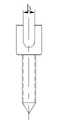
附图3是本发明一种骨盆内固定器的骨盆内固定钉的平面视图。Accompanying
附图4是带有连接器的骨盆内固定器套件的结构示意图。Accompanying
附图5是骨盆内固定器连接器的结构分解示意图。Accompanying drawing 5 is the exploded schematic view of the structure of the pelvic internal fixator connector.
附图6是骨盆内固定器连接器的组装示意图。Accompanying drawing 6 is the assembly diagram of connector of internal fixator in pelvis.
具体实施方式Detailed ways
下面结合附图对本发明提供的具体实施方式作详细说明。The specific embodiments provided by the present invention will be described in detail below in conjunction with the accompanying drawings.
附图中涉及的附图标记和组成部分如下所示:The reference signs and components involved in the accompanying drawings are as follows:
1.骨盆内固定钉 2.支撑棒1. Pelvic
3.紧固螺母 4.连接器3.
11.螺杆 12.U型管套11.
121.U型管套加长段 122.弧形槽121. U-shaped
123.外螺纹 124.内螺纹123.
125.切断槽 31.紧固螺母内孔125. Cutting
41.连接器一 42.连接器二41.
43.紧定螺钉 44.紧固螺钉43. Set
411.紧定螺钉螺孔 412.连接器连接螺孔411. Set
421.连接器连接孔道421. Connector connection channel
请参照附图1,附图1是本发明一种骨盆内固定器的结构示意图。所述的骨盆内固定器由骨盆内固定钉1、支撑棒2和紧固螺母3组成,手术使用时每组内固定器应至少包含两枚骨盆内固定钉1、一根支撑棒1和两个紧固螺母3。Please refer to accompanying drawing 1, accompanying drawing 1 is the structural representation of a kind of pelvic internal fixator of the present invention. The pelvic internal fixator is composed of pelvic
请参照附图2,附图2是本发明一种骨盆内固定器的结构分解示意图。所述的骨盆内固定钉1由螺杆11和U型管套12组成,所述的螺杆11长30-50mm,直径5.5-9.5mm,螺杆11外设有全螺纹,直通至螺杆11顶端,结构类似于全螺纹的皮质骨螺钉下端螺杆。骨盆内固定钉1结构与常用的椎弓根螺钉结构相似,但是使用椎弓根螺钉不能进行骨盆固定,因为椎弓根螺钉固定在椎体内,椎体内为松质骨,所以椎弓根螺钉下端螺杆类似于松质骨螺钉,而骨盆为皮质骨-松质骨-皮质骨结构,如要牢固固定,需要将这三层结构均穿透才有较好的把持力,因此需要类似皮质骨螺钉的本发明的螺杆11固定。Please refer to accompanying drawing 2, accompanying drawing 2 is the structural exploded view of a kind of pelvic internal fixator of the present invention. The
所述的U型管套12是一个顶端敞通的空心管套,底端封闭与螺杆11头部连成一体,设置有一横贯底部的弧形槽122,请参照附图3,附图3是本发明一种骨盆内固定器的骨盆内固定钉的平面视图,如图3所示,弧形槽的宽度b为5.5-6.5mm,与支撑棒2的直径相同。该弧形槽122将空心管套的管壁分割成相对应的具有内螺纹124的两个弧形壁,这两个弧形壁的外部也都设有外螺纹123。为了方便手术,所述的U型管套12上方可以设有U型管套加长段121,U型管套加长段121通常为U型管套12长度的1-5倍,两部分通过切断槽125相连,切断槽125是将管壁切薄或者通过点连接的方式连接加长段,手术结束前可沿切断槽125将U型管套加长段121去除。The
所述的支撑棒2是一根细长的实心圆柱形金属杆,长100-200mm,直径5.5-6.5mm,有一定的柔性,可以根据患者的骨盆形状进行预弯,同时预弯后可以保持固定的形状,达到支撑的作用。支撑棒2可以通过U型管套12的上端开口处放在弧形槽122上,或者直接通过弧形槽122穿进U型管套12中。所述的支撑棒2放置在U型管套12的弧形槽122中并确定好相对位置后,即可将紧固螺母3通过内螺纹124旋进U型管套12,通过紧固螺母3和支撑棒2以及弧形槽122的摩擦力实现支撑棒2和骨盆内固定钉1的固定。所述的紧固螺母3拧紧固定好支撑棒2后,其高度不会超过U型管套12的切断槽125处,使得去除U型管套加长段121 后,紧固螺母3上端不会突出在U型管套12外。所述的紧固螺母3中心部位为紧固螺母内孔31,图2中显示的紧固螺钉内孔31为六角形,还可以是八角形、四角形、三角形、一字形、十字形、梅花形孔或凹槽。The
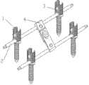
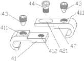
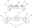
需要说明的是,手术使用时每组内固定器应至少包含两枚骨盆内固定钉1、一根支撑棒1和两个紧固螺母3,如图1所示,也可以在同一根支撑棒上增加多枚骨盆内固定钉1和紧固螺母3。当一根支撑棒2的结构不能起到很好的固定作用时,可以增加一根支撑棒2和相对应的骨盆内固定钉1。请参照附图4,附图4是带有连接器的骨盆内固定器套件的结构示意图。如图4所示,当两根支撑棒2为平行放置时,两根支撑棒2之间可以用连接器4来连接固定,使用后可提高整个固定系统的稳定性。请参照附图5,附图5是骨盆内固定器连接器的结构分解示意图。所述的连接器由连接器一41、连接器二42、紧定螺钉43和紧固螺钉44组成。所述的连接器一41和连接器二42都呈钩型,由平直段和弯曲段组成,弯曲段的曲面直径与支撑棒2直径相同,用于勾住支撑棒2。所述的连接器一41和连接器二42上靠近弯曲段上各设有一紧定螺钉螺孔411,连接器一41的平直段末端设有一连接器连接螺孔412,连接器二42的平直段末端设有一长圆形的连接器连接孔道421。请参照附图5,附图5是骨盆内固定器连接器的组装示意图。组装时,将连接器一41和连接器二42的弯曲段分别卡在两根支撑棒2上,拧紧两个紧定螺钉43,使紧定螺钉43的下端伸出连接器4的平面,紧定螺钉43的下端卡住支撑棒2,从而起到固定连接器4和支撑棒2的作用,请参照附图6下图,附图6下图是连接器固定状态剖视图。调整好连接器一41和连接器二42的相对位置,拧紧紧固螺钉44,从而固定好连接器4的两个部分。所述的紧定螺钉43和紧固螺钉44的中心部位可以是六角形、八角形、四角形、三角形、一字形、十字形、梅花形孔或凹槽。It should be noted that each set of internal fixators should contain at least two pelvic
需要说明的是,进行骨盆固定手术时,首先将骨盆内固定钉1分别固定在需要复位固定的骨骼上,安装配套的复位装置,复位装置与内固定器连接部位为一个带内螺纹的管套,将复位装置管套套在骨盆内固定钉1的U型管套12上,通过骨盆内固定钉1的外螺纹123旋紧固定(旋到U型管套12底部),通过扳动调整复位装置带动骨盆内固定钉1使骨骼复位,将外固定器固定在所需位置,根据患者的骨骼特点预弯支撑棒2,并将支撑棒2穿过U型管套12,使用工具穿过外固定器管套内部,在管套内部将紧固螺母3旋紧,即将支撑棒2与骨盆内固定钉1固定。如采用了多个支撑棒2,则可以在此时安装连接器4。内固定器固定好后,将复位装置拆除,通过折钉器沿切断槽125将U型管套加长段121去除,即可固定好整个骨骼内固定器。It should be noted that when performing pelvic fixation surgery, the pelvic
具体手术过程:Specific surgical procedure:
1) 首先,切开皮肤、皮下组织、肌肉等,将需要固定的骨盆显露。1) First, cut the skin, subcutaneous tissue, muscles, etc., and expose the pelvis that needs to be fixed.
2) 在骨折线两侧或预截骨处两侧的骨盆上,分别垂直各拧入合适长度1枚骨盆内固定钉1。在固定钉上U形套管外侧拧紧T形提拉复位装置(该专利中未加说明)。2) On the pelvis on both sides of the fracture line or on both sides of the pre-osteotomy, one pelvic
3) 当操作为截骨术时,需在髋臼上方将骨盆截断,并将同侧耻骨支和坐骨支截断,便于髋臼上部翻转矫正;当操作为骨折切开固定术时,只需暴露拟固定的部位即可。3) When the operation is osteotomy, the pelvis needs to be cut off above the acetabulum, and the pubic rami and ischial ramus on the same side should be cut off to facilitate the correction of the upper part of the acetabulum; when the operation is open fracture fixation, it is only necessary to expose the It is enough to fix the position.
4) 使用复位装置,通过提拉、旋转等方法,将骨盆骨折复位或将截断后的髋臼上部外旋等,使髋臼获得满意深度;并拧紧复位装置各部件,使骨盆临时固定。4) Use the reset device to reset the pelvic fracture or externally rotate the upper part of the truncated acetabulum by means of pulling and rotating to obtain a satisfactory depth of the acetabulum; and tighten the parts of the reset device to temporarily fix the pelvis.
5)在预先固定的两枚骨盆内固定钉1连线上,再在骨折或截骨线两侧各拧入0-3枚骨盆内固定钉1(可以避免后期支撑棒2过度折弯)。5) Screw in 0-3 pelvic
6)通过预弯装置将支撑棒2折弯成满意形状,放入所有的U形套管12内,观察支撑棒2与各U形套管12是否服帖。6) Use the pre-bending device to bend the
7) 通过中空的复位装置,将内置的紧固螺母3与支撑棒2锁紧。依次拧紧所有紧固螺母3和支撑棒2的接口。7) Lock the built-in
8) 将复位装置拆除,通过折钉器沿切断槽125将骨盆内固定钉1上多余的U型管套加长段121折断并去除。8) Remove the reset device, and use a nail breaker to break and remove the redundant
9) 如固定不满意,可依上述方法再行另一组固定装置。9) If the fixation is not satisfactory, another set of fixation devices can be performed according to the above method.
10)同时,可以通过连接器4将两组固定装置连接,增加其固定牢固度。10) At the same time, the two sets of fixing devices can be connected through the
11)逐层缝合。术毕。11) Sew layer by layer. Surgery completed.
以上所述仅是本发明的优选实施方式,应当指出,对于本技术领域的普通技术人员,在不脱离本发明方法的前提下,还可以做出若干改进和补充,这些改进和补充也应视为本发明的保护范围。The above is only a preferred embodiment of the present invention, it should be pointed out that for those of ordinary skill in the art, without departing from the method of the present invention, some improvements and supplements can also be made, and these improvements and supplements should also be considered Be the protection scope of the present invention.
Claims (7)
Priority Applications (1)
| Application Number | Priority Date | Filing Date | Title |
|---|---|---|---|
| CN 201110122458CN102178557B (en) | 2011-05-12 | 2011-05-12 | Pelvic internal fixation unit and application thereof |
Applications Claiming Priority (1)
| Application Number | Priority Date | Filing Date | Title |
|---|---|---|---|
| CN 201110122458CN102178557B (en) | 2011-05-12 | 2011-05-12 | Pelvic internal fixation unit and application thereof |
Publications (2)
| Publication Number | Publication Date |
|---|---|
| CN102178557A CN102178557A (en) | 2011-09-14 |
| CN102178557Btrue CN102178557B (en) | 2013-01-23 |
Family
ID=44564965
Family Applications (1)
| Application Number | Title | Priority Date | Filing Date |
|---|---|---|---|
| CN 201110122458Expired - Fee RelatedCN102178557B (en) | 2011-05-12 | 2011-05-12 | Pelvic internal fixation unit and application thereof |
Country Status (1)
| Country | Link |
|---|---|
| CN (1) | CN102178557B (en) |
Families Citing this family (4)
| Publication number | Priority date | Publication date | Assignee | Title |
|---|---|---|---|---|
| CN102697551A (en)* | 2012-05-24 | 2012-10-03 | 浙江科惠医疗器械有限公司 | Dynamic locking screw |
| CN106510822B (en)* | 2016-10-18 | 2023-08-01 | 熊鹰 | Combined pelvis drift minimally invasive internal fixing device |
| CN112137703B (en)* | 2020-09-27 | 2022-03-25 | 西安市红会医院 | Pelvis fracture reduction device and using method thereof |
| CN115886960A (en)* | 2022-12-29 | 2023-04-04 | 天津医科大学总医院 | Pelvic short-range closed-loop fixation device, system and method based on descending pubic branch intramedullary nail |
Citations (3)
| Publication number | Priority date | Publication date | Assignee | Title |
|---|---|---|---|---|
| CN1424000A (en)* | 2002-12-31 | 2003-06-18 | 中国人民解放军南京军区南京总医院 | Pier bridge style screw system for vertebral arch pedicle |
| CN201290757Y (en)* | 2008-11-18 | 2009-08-19 | 浙江科惠医疗器械有限公司 | Injectable pediculus arcus vertebrae screw |
| CN202078383U (en)* | 2011-05-12 | 2011-12-21 | 上海市第六人民医院 | Internal fixator for pelvis |
- 2011
- 2011-05-12CNCN 201110122458patent/CN102178557B/ennot_activeExpired - Fee Related
Patent Citations (3)
| Publication number | Priority date | Publication date | Assignee | Title |
|---|---|---|---|---|
| CN1424000A (en)* | 2002-12-31 | 2003-06-18 | 中国人民解放军南京军区南京总医院 | Pier bridge style screw system for vertebral arch pedicle |
| CN201290757Y (en)* | 2008-11-18 | 2009-08-19 | 浙江科惠医疗器械有限公司 | Injectable pediculus arcus vertebrae screw |
| CN202078383U (en)* | 2011-05-12 | 2011-12-21 | 上海市第六人民医院 | Internal fixator for pelvis |
Also Published As
| Publication number | Publication date |
|---|---|
| CN102178557A (en) | 2011-09-14 |
Similar Documents
| Publication | Publication Date | Title |
|---|---|---|
| JP3236938B2 (en) | Adhesion stabilization chamber | |
| AU2013295399B2 (en) | Elongated pin for an external modular fixation system for temporary and/or permanent fixation applications and external modular fixation system | |
| CN203089338U (en) | Atlantoaxial anterior approach restoration inner fixing device | |
| US20140031822A1 (en) | Method for Treating a Fracture of a Bone Having a Medullary Canal | |
| ES2400600T3 (en) | Device for stabilizing long bone fractures | |
| AU2004224580B2 (en) | Hybrid interlocking proximal femoral fracture fixation | |
| CN203089337U (en) | Minitype internal fixation and fusion device of atlantoaxial lateral mass joint | |
| CN108742810A (en) | A kind of anti-rotation intramedullary nail system of near end of thighbone | |
| CN102178557B (en) | Pelvic internal fixation unit and application thereof | |
| CN101856262A (en) | Proximal Tibial Plateau Medial Posterior Anatomical Supported Locking Plate | |
| CN113827330B (en) | Internal fixation system for anatomical reduction of vertebral body and bone grafting in vertebral body of spinal fracture | |
| CN203677225U (en) | External fixing device for emergency treatment recovery of limb long-pipe-bone | |
| CN202078383U (en) | Internal fixator for pelvis | |
| CN204484283U (en) | A kind ofly promote the bionical inner fixing device of the porous of union of fracture | |
| CN205251663U (en) | Excellent fixing system of ring nail before special percutaneous wicresoft of pelvis | |
| CN104146756B (en) | A kind of locking axially fusion internal fixation system of minimally invasive lumbosacral spine | |
| CN106725788A (en) | A kind of wing plate with curved surface internal fixation system for spondylolysis and spondylolithesis of the lumbar spine | |
| CN204410945U (en) | The anterior approach cranium neck fixture improved | |
| RU2240072C2 (en) | Device for carrying out anterior spondylodesis in the cases of unstable fractures and dislocation fracture of cervical vertebral column segment | |
| CN106236331B (en) | A kind of Invasive lumbar fusion device | |
| CN204016461U (en) | A kind of Wicresoft waist sacral locking axis is to merging internal fixation system | |
| CN208876724U (en) | A kind of os pelvicum fracture reset device assembly | |
| RU195374U1 (en) | Universal axial shaft for transpedicular fixation of the spine | |
| RU2364366C1 (en) | Method of traumatic kyphosis correction in burst spine fractures in children | |
| CN2311244Y (en) | Spondyloschisis fixer |
Legal Events
| Date | Code | Title | Description |
|---|---|---|---|
| C06 | Publication | ||
| PB01 | Publication | ||
| C10 | Entry into substantive examination | ||
| SE01 | Entry into force of request for substantive examination | ||
| C14 | Grant of patent or utility model | ||
| GR01 | Patent grant | ||
| CF01 | Termination of patent right due to non-payment of annual fee | ||
| CF01 | Termination of patent right due to non-payment of annual fee | Granted publication date:20130123 |