CN102178443B - Micro-pressure cooker - Google Patents
Micro-pressure cookerDownload PDFInfo
- Publication number
- CN102178443B CN102178443BCN 201110071153CN201110071153ACN102178443BCN 102178443 BCN102178443 BCN 102178443BCN 201110071153CN201110071153CN 201110071153CN 201110071153 ACN201110071153 ACN 201110071153ACN 102178443 BCN102178443 BCN 102178443B
- Authority
- CN
- China
- Prior art keywords
- pot
- valve core
- air release
- cover
- release valve
- Prior art date
- Legal status (The legal status is an assumption and is not a legal conclusion. Google has not performed a legal analysis and makes no representation as to the accuracy of the status listed.)
- Active
Links
Images


Landscapes
- Cookers (AREA)
Abstract
Description
Translated fromChinese技术领域technical field
本发明涉及电热锅具,特别涉及在微压工作状态下工作的电热锅具。The invention relates to an electric heating pot, in particular to an electric heating pot working under a micro-pressure working state.
背景技术Background technique
传统的电饭锅其盖体上设置有直通外面空气的通气孔,锅内基本上没有任何压力,锅内沸腾的水会带走大量的热量,使这种传统的电饭锅的能耗非常高;其次为了维持锅内水沸腾所需热量,必须将发热器的功率和体积适当做大。压力锅特别是最近几年开始发展起来的电压力锅,虽然在能耗方面大大降低,但锅内高压不仅对锅内食物形成破坏,而且要求锅体的结构强度高,否则非常容易发生爆炸,因此高压锅的制造成本高,始终存在安全隐患。The lid of the traditional electric rice cooker is provided with vent holes leading directly to the outside air. There is basically no pressure in the pot, and the boiling water in the pot will take away a large amount of heat, which makes the energy consumption of this traditional electric rice cooker very high. High; Secondly, in order to maintain the heat required for boiling the water in the pot, the power and volume of the heater must be appropriately enlarged. Pressure cookers, especially electric pressure cookers that have been developed in recent years, although the energy consumption has been greatly reduced, the high pressure in the pot not only damages the food in the pot, but also requires a high structural strength of the pot body, otherwise it is very easy to explode, so the pressure cooker The manufacturing cost is high, and there are always potential safety hazards.
对于微压锅具,其基本的原理在于始终维持锅内的水温接近沸腾的临界点但极少超过沸腾点,这样不仅可以使锅内的食物可以在接近沸腾点温度范围内煮沸,但又不会有大量的水被蒸发而损耗热量,使锅具的能耗不仅小于高压锅而且远远小于普通传统的电饭锅。我们知道从水变为蒸汽将消耗大量的能量,而这些能量消耗后全部排出到锅外,不仅消耗了能量而且使室内温度升高。为此就如何准确地控制锅内食物的温度是该种微压锅具的实施难点。如果全部采用电子式检测控制方法,制造成本不仅非常高,而且由于检测元件的参数漂移,极难控制准确。For the micro-pressure cooker, the basic principle is to always keep the water temperature in the pot close to the boiling point but seldom exceeds the boiling point, so that not only can the food in the pot be boiled in the temperature range close to the boiling point, but not A large amount of water will be evaporated to lose heat, so that the energy consumption of the cooker is not only less than that of a pressure cooker but also far less than that of a conventional electric rice cooker. We know that changing from water to steam will consume a lot of energy, and all of these energy are discharged out of the pot after consumption, which not only consumes energy but also raises the indoor temperature. How to accurately control the temperature of the food in the pot is the implementation difficulty of this kind of micro-pressure cooker for this reason. If all electronic detection and control methods are used, the manufacturing cost is not only very high, but also due to the parameter drift of the detection element, it is extremely difficult to control accurately.
现有技术方案中,比较典型的是中国专利申请号为200820005938.2,名称为“一种汽动电热蒸煮器具”的技术方案,其披露了一种汽动电热蒸煮器具,它属于厨房用电热蒸煮器具,是利用蒸汽动力控制温度在常压下工作的电饭锅产品技术。它包括锅盖、内锅、电热器;内锅设置在电热器上;它还包括一个动力控制装置,该装置包含固定结构件、开关、动力传递件,其中的开关与电热器串联接入电源。该发明虽然也提及了一种低压电饭锅的结构和原理,但该发明的实质性特点还是中国专利申请号为200620007791.1专利技术的一种翻版,其借用压力锅的原理,利用锅盖本身的变形或位移,或者利用内锅的位移来传递锅内压力,从而仍然必须使锅内的压力比较高。为此该技术方案的要点如其说明书所描述,必须重点考虑锅盖、密封圈等器件的重量与锅内压力的适配和平衡,过重或结构强度过高则使它变成了压力锅,过轻或结构轻度过低则使它不能适用于实际应用和安全要求。由于其利用锅盖、密封圈等器件的重量与锅内压力适配和平衡,为此不可避免地其内锅内的压力仍然比较高,相应其内锅内的温度也就比较高,很难将锅内水的温度基本控制在其沸点以下但又接近沸点。特别是当其设计为锅盖及其密封圈都可以移动或变形的结构时,其锅盖必须至少设置为动盖和非动盖两部分,即非动盖部分与锅体铰接或扣牙连接,而动盖部分可上下移动地连接在非动盖部分的内侧,为此该种设计的锅盖结构和控制结构仍然复杂,成本也比较高,与电饭锅追求结构简单成本低的基本目标不一致。Among the existing technical solutions, the typical Chinese patent application number is 200820005938.2, and the technical solution named "a steam-driven electric heating cooking appliance" discloses a steam-driven electric heating cooking appliance, which belongs to the kitchen electric heating cooking appliance , is a rice cooker product technology that uses steam power to control the temperature and work under normal pressure. It includes a pot cover, an inner pot, and an electric heater; the inner pot is set on the electric heater; it also includes a power control device, which includes a fixed structural part, a switch, and a power transmission part, and the switch and the electric heater are connected to the power supply in series . Although this invention also mentioned the structure and principle of a low-voltage electric rice cooker, the substantive feature of this invention is still a replica of the patented technology of Chinese Patent Application No. 200620007791.1. deformation or displacement, or use the displacement of the inner pot to transmit the pressure in the pot, so the pressure in the pot must still be relatively high. For this reason, the main points of this technical solution are as described in its instruction manual. It is necessary to focus on the adaptation and balance of the weight of devices such as pot lids and sealing rings and the pressure in the pot. If it is too heavy or the structural strength is too high, it becomes a pressure cooker. Lightweight or low structural lightness makes it unsuitable for practical applications and safety requirements. Because it utilizes the weight of devices such as pot cover and sealing ring to adapt and balance the pressure in the pot, the pressure in the inner pot is still relatively high for this reason, and the temperature in the corresponding inner pot is also relatively high, which is difficult The temperature of the water in the pot is basically controlled below its boiling point but close to the boiling point. Especially when it is designed as a structure in which both the pot cover and its sealing ring can be moved or deformed, the pot cover must be set at least in two parts: a moving cover and a non-moving cover, that is, the non-moving cover part is hinged or buckled to the pot body. , while the movable cover part can be moved up and down and connected to the inner side of the non-movable cover part. Therefore, the structure and control structure of the pot cover of this design are still complicated, and the cost is relatively high. Inconsistent.
其次,中国专利申请号为201010218284.3,名称为“一种动盖控制装置”的发明专利,披露了一种动盖控制装置,它属于厨房用电热烹饪器具领域,是采用压力控制方式,工作在常压范围的一种动盖控制装置。它包括锅盖部件、锅体部件、内锅、电热盘;在锅盖部件与锅体部件相接处的一侧设置一个控制机构,所述的控制机构包括传递件和开关,用于传递锅盖部件的位移力或重力的传递件与开关呈上下对应设置;在所述的锅盖部件与锅体部件相接处的另一侧设置一个支点机构,所述的支点机构,包括设置在锅盖部件和锅体部件上的固定件和扣插件,固定件和扣插件相互结合,锅盖部件以二者的结合点为支点作开合位移。根据该发明说明书的记载,其核心内容是利用铰接结构将锅盖和锅体铰接连接,由于锅内蒸汽动力的推动,锅盖可以在锅体上翻动而排汽。很明显该种结构的炊具,其锅内压力的大小控制也如中国专利申请号为200820005938.2的专利技术一样,不仅受制于锅盖、密封圈的重量和铰接结构的阻力,而且锅盖在翻动的过程中将锅内的蒸汽全部溢出,也损耗了能量,即能耗虽然远小于普通的电饭锅但远大于封闭式的压力锅。当锅内蒸汽积聚到一定压力时使锅盖在打开的瞬间排出蒸汽,此后锅盖又马上下移复位使控制开关接通电源向加热器供电,实际上是使锅内的水基本上处于沸腾状态,即始终超过沸腾临界状态。其次该种结构的炊具,由于其内锅是密封状态下工作,当水沸腾前就会存在冷空气溢出的问题,如此冷空气在锅内积聚也能使锅盖频繁地翻动,进而使加热器在水达到沸腾点前也频繁地启动或停止,这样大大延缓了煮饭的时间;还有该种结构的炊具也未考虑在未工作时的开盖负压和合盖正压问题。Secondly, the Chinese patent application number is 201010218284.3, and the invention patent titled "a movable cover control device" discloses a movable cover control device, which belongs to the field of kitchen electric heating cooking utensils. A dynamic cover control device for pressure range. It includes a pot cover part, a pot body part, an inner pot, and an electric heating plate; a control mechanism is provided on the side where the pot cover part and the pot body part meet, and the control mechanism includes a transmission part and a switch for transferring the pot The displacement force or gravity transmission part of the cover part and the switch are arranged correspondingly up and down; a fulcrum mechanism is arranged on the other side of the joint between the pot cover part and the pot body part, and the fulcrum mechanism includes a pot The fixing part and the buckle insert on the cover part and the pot body part are combined with each other, and the pot cover part takes the joint point of the two as the fulcrum for opening and closing displacement. According to the description of the invention, its core content is to use a hinged structure to hinge the pot cover and pot body. Due to the promotion of steam power in the pot, the pot cover can be turned on the pot body to exhaust steam. It is obvious that the cooker with this structure, the size control of the pressure in the pot is the same as the patented technology with the Chinese patent application number 200820005938.2, which is not only limited by the weight of the pot cover and the sealing ring and the resistance of the hinged structure, but also the pot cover is turned. During the process, all the steam in the pot is overflowed, which also consumes energy. Although the energy consumption is far less than that of a common electric cooker, it is far greater than that of a closed pressure cooker. When the steam in the pot accumulates to a certain pressure, the steam will be discharged at the moment the pot cover is opened, and then the pot cover will move down and reset immediately, so that the control switch is connected to the power supply to the heater, which actually makes the water in the pot basically boil. State, that is, always exceeds the boiling critical state. Secondly, the cooker of this kind of structure, because its inner pot works in a sealed state, there will be a problem of cold air overflowing before the water boils, so the accumulation of cold air in the pot can also cause the pot cover to turn frequently, and then the heater Also start or stop frequently before water reaches boiling point, have delayed the time of cooking like this; Also have the cooker of this kind of structure to also not consider uncapping negative pressure and closing positive pressure problem when not working.
发明内容Contents of the invention
根据现有技术的不足,本发明试图更加准确地将锅内的温度控制在沸腾的临界点并减少锅内蒸汽的散发,并且使炊具在未工作时容易开盖和合盖,有利于操作。为此,本发明提出一种微压锅具,包括锅体、内锅、锅盖和加热器,所述锅盖与所述内锅之间设置有内锅密封圈,在所述锅体或锅盖上设置有信号开关;其特征在于,在所述锅盖上设置有连通所述内锅的容腔和外部的第一盖孔,所述第一盖孔中设置可以上下活动的第一泄气阀芯,所述第一泄气阀芯与所述锅盖之间具有间隙,所述第一泄气阀芯的下部设置有第一密封圈,所述第一密封圈与所述锅盖之间具有间隙,所述信号开关与所述第一泄气阀芯之间设置传动臂;当所述第一泄气阀芯上移时,所述第一密封圈堵封所述第一盖孔,所述第一泄气阀芯通过所述传动臂驱动所述信号开关动作。According to the deficiencies of the prior art, the present invention attempts to more accurately control the temperature in the pot at the critical point of boiling and reduce the distribution of steam in the pot, and makes it easy to open and close the cover when the cooker is not working, which is beneficial to operation. For this reason, the present invention proposes a kind of micro-pressure cooker, comprises pot body, inner pot, pot cover and heater, and inner pot sealing ring is arranged between described pot cover and described inner pot, and described pot body or The pot cover is provided with a signal switch; it is characterized in that a first cover hole communicating with the cavity of the inner pot and the outside is provided on the pot cover, and a first cover hole that can move up and down is provided in the first cover hole. The air release valve core has a gap between the first air release valve core and the pot cover, the bottom of the first air release valve core is provided with a first sealing ring, and there is a gap between the first sealing ring and the pot cover. There is a gap, and a transmission arm is set between the signal switch and the first air release valve core; when the first air release valve core moves up, the first sealing ring blocks the first cover hole, and the The first air release valve core drives the signal switch to act through the transmission arm.
所述锅体是所述微压锅具的主要承载部,其内设置有内锅、加热器及所述微压锅具的电控系统;所述锅盖位于所述锅体的上面并与所述内锅之间设置内锅密封圈,从而通过所述内锅密封圈不仅可以积聚锅内的蒸汽压力而且可以使所述内锅内的食物在密封的情况下烹饪。所述信号开关是一种电器控制件,例如单稳态的微动开关、接近开关或光电传感开关等,它可以在所述传动臂或所述第一泄气阀芯的直接驱动下切断加热器的电源或通过所述微压锅具的控制系统切断加热器的电源。当所述传动臂或所述第一泄气阀芯失去驱动力时,所述信号开关复位使所述加热器又恢复工作。为了使所述微压锅具工作具有一定的智能功能,最好在所述微压锅具的控制系统中再设置自动计时功能,即在所述信号开关复位后所述控制系统可以根据锅内温度、压力等参数自动确定再次加热的时间节奏。The pot body is the main bearing part of the micro-pressure cooker, and an inner pot, a heater and an electric control system of the micro-pressure cooker are arranged in it; An inner pot sealing ring is arranged between the inner pots, so that the steam pressure in the pot can not only be accumulated by the inner pot sealing ring, but also the food in the inner pot can be cooked in a sealed condition. The signal switch is an electrical control component, such as a monostable micro switch, a proximity switch or a photoelectric sensor switch, etc., which can cut off the heating under the direct drive of the transmission arm or the first air release valve core. The power supply of the heater or cut off the power supply of the heater by the control system of the micro pressure cooker. When the driving force of the transmission arm or the first air release valve core is lost, the signal switch is reset to make the heater work again. In order to make the work of the micro-pressure cooker have certain intelligent functions, it is better to set an automatic timing function in the control system of the micro-pressure cooker, that is, after the signal switch is reset, the control system can Parameters such as temperature and pressure automatically determine the time rhythm of reheating.
所述锅盖可以是单层的结构,也可以是双层的结构,在所述锅盖是双层结构的情况下,所述第一盖孔可以仅仅只需穿通所述锅盖的内盖部,所述第一泄气阀芯释放的蒸汽或冷空气可以通过其他通道穿过所述锅盖的外壳体释放到外面。The pot cover can be a single-layer structure or a double-layer structure. In the case of a double-layer structure, the first cover hole only needs to pass through the inner cover of the pot cover part, the steam or cold air released by the first air release valve core can be released to the outside through other channels through the outer shell of the pot cover.
所述第一泄气阀芯至少具有杆体部,即所述第一泄气阀芯可以是呈“I”字形、“T”字形、“工”字形等形状。所述第一泄气阀芯可以自由活动地设置在所述第一盖孔内,并且所述第一泄气阀芯与所述锅盖之间具有间隙(即所述第一泄气阀芯的杆体部的外径小于所述第一盖孔的内径)从而让所述内锅内的蒸汽或冷空气可以穿过。所述第一泄气阀芯的定位方式也有多种设计方案,主要是根据所述第一泄气阀芯的具体结构进行选择。在第一泄气阀芯的杆体部的下部设置第一密封圈。为了恰当地设置所述第一泄气阀芯的重量大小,还可以在所述第一泄气阀芯的中心部位设置盲孔,根据不同的盲孔大小来适配所述第一泄气阀芯的重量。The first air release valve core has at least a rod body, that is, the first air release valve core may be in the shape of "I", "T", or "I". The first air release valve core can be freely and freely arranged in the first cover hole, and there is a gap between the first air release valve core and the pot cover (that is, the rod body of the first air release valve core The outer diameter is smaller than the inner diameter of the first cover hole) so that the steam or cold air in the inner pot can pass through. There are also various design schemes for the positioning of the first air release valve core, which are mainly selected according to the specific structure of the first air release valve core. A first sealing ring is arranged at the lower part of the rod body of the first air release valve core. In order to properly set the weight of the first air release valve core, a blind hole can also be set in the center of the first air release valve core, and the weight of the first air release valve core can be adapted according to different blind hole sizes .
所述第一密封圈与所述锅盖之间具有间隙,是指所述第一密封圈的上表面与所述锅盖的下表面之间具有一定的间隙,从而在所述第一泄气阀芯未上移时所述内锅内的冷空气或蒸汽可以通过该间隙、所述第一泄气阀芯与所述锅盖之间的间隙释放出去,而当所述第一泄气阀芯上移时,所述第一密封圈可以堵住上述间隙所组成的出气通道。其中所述第一密封圈的横截面可以呈O形或U形,从而使所述第一密封圈可以在所述第一泄气阀芯上移时形成一种缓冲。There is a gap between the first sealing ring and the pot cover, which means that there is a certain gap between the upper surface of the first sealing ring and the lower surface of the pot cover, so that the first air release valve When the core does not move up, the cold air or steam in the inner pot can be released through the gap, the gap between the first air release valve core and the pot cover, and when the first air release valve core moves up , the first sealing ring can block the air outlet channel formed by the gap. The cross-section of the first sealing ring can be O-shaped or U-shaped, so that the first sealing ring can form a buffer when the first air-discharging valve core moves upward.
为了使所述内锅内的冷空气或蒸汽溢出顺畅,在所述第一泄气阀芯呈“T”字形或“工”字形的情况下,最好是在所述锅盖与所述第一泄气阀的上部凸出边之间的接触面上设置有凸台或粗糙面,即可以在所述锅盖上表面设置凸台或粗糙面,也可以在所述第一泄气阀的上部凸出边的下表面设置凸台或粗糙面,从而便于冷空气或蒸汽可以穿过这些凸台或粗糙面所形成的空隙溢出。In order to make the cold air or steam in the inner pot overflow smoothly, when the first air release valve core is in the shape of "T" or "I", it is better to connect the pot cover with the first The contact surface between the upper protruding edges of the air release valve is provided with a boss or a rough surface, that is, a boss or a rough surface can be provided on the upper surface of the pot cover, or it can protrude on the upper part of the first air release valve. Bosses or rough surfaces are arranged on the lower surface of the side so that cold air or steam can escape through the gaps formed by these bosses or rough surfaces.
根据上述技术方案,当加热器工作使所述内锅的水温上升,在接近沸点前就会有大量的冷空气溢出,而冷空气在溢出时由于其可以从容地从所述第一盖孔中溢出而在所述内锅内不会迅速形成压力,所述第一泄气阀芯不会上移;当所述内锅的水温上升接近沸点时,少量的水分子汽化急剧膨胀(体积膨胀的比率大约为1600倍)而溢出水面,迅速在所述内锅的水面上形成一定的气压,该气压可以立即推动所述第一泄气阀芯上移,所述第一泄气阀芯上移时不仅封闭所述第一盖孔而且可以推动所述传动臂动作,所述传动臂再驱动所述信号开关动作,切断加热器的电源使其立即停止加热,阻止所述内锅内的水进一步汽化溢出。当所述内锅内的温度下降蒸汽压力降低时,所述第一泄气阀芯落下,所述信号开关也复位,加热器再次开始加热。According to the above technical solution, when the heater works to increase the temperature of the water in the inner pot, a large amount of cold air will overflow before approaching the boiling point, and when the cold air overflows, it can pass through the first cover hole calmly. Overflow and can not form pressure rapidly in described inner pot, and described first leak valve core can not move up; When the water temperature of described inner pot rises close to boiling point, a small amount of water molecule vaporizes and expands rapidly (the ratio of volume expansion about 1600 times) and overflow the water surface, quickly form a certain air pressure on the water surface of the inner pot. The first cover hole can also push the transmission arm to move, and the transmission arm drives the signal switch to cut off the power supply of the heater to immediately stop heating, preventing the water in the inner pot from further vaporizing and overflowing. When the temperature in the inner pot drops and the steam pressure drops, the first air release valve core falls, the signal switch also resets, and the heater starts heating again.
根据上述技术方案,所述内锅内的蒸汽压强在所述第一泄气阀芯的下表面形成的推力仅仅只需克服所述第一泄气阀芯及其密封圈的重量和所述传动臂的压力就可以将所述第一盖孔封闭并使所述加热器停止工作,与现有技术中蒸汽必须使整个锅盖移动或变形相比,适当选择所述第一密封圈的受力面积大小,可以使所述第一泄气阀芯在刚刚出现水蒸气时就可以快速动作,使其动作更加及时和灵敏,驱动气压更小,释放的蒸汽也少,实际上也即是对水温控制更加精确,浪费的能量少;其次该结构还可以排放沸腾前的水中冷空气,防止所述信号开关在水温达到沸点前误动作;另外,还可以使所述微压锅具未工作而需要合盖时顺利排出锅内的正压空气而顺利合盖,也可以在快速开启所述锅盖时消除所述内锅容腔内的负压,使开盖变得顺利。According to the above technical solution, the thrust formed by the steam pressure in the inner pot on the lower surface of the first air release valve core only needs to overcome the weight of the first air release valve core and its sealing ring and the weight of the transmission arm. The pressure can close the first cover hole and stop the heater. Compared with the steam in the prior art that must make the entire pot cover move or deform, the force-bearing area of the first sealing ring should be properly selected. , can make the first air-discharging spool move quickly when water vapor just appears, making its action more timely and sensitive, the driving air pressure is smaller, and the released steam is also less, in fact, it is more accurate to control the water temperature , less energy wasted; secondly, this structure can also discharge the cold air in the water before boiling to prevent the signal switch from malfunctioning before the water temperature reaches the boiling point; in addition, it can also make the micro pressure cooker not work and need to close The positive pressure air in the pot is smoothly discharged to close the cover smoothly, and the negative pressure in the inner pot cavity can also be eliminated when the pot cover is opened quickly, so that the cover can be opened smoothly.
其次为了使所述微压锅具在未工作但已经接通电源并且所述锅盖已经合盖的情况下防止所述加热器接通工作,可以在所述控制系统中设置专用的加热启动按钮和保温按钮,或设置其它专门的检测器件予以控制。Secondly, in order to prevent the heater from turning on and working when the micro-pressure cooker is not working but has been powered on and the lid is closed, a dedicated heating start button can be set in the control system and heat preservation button, or set other special detection devices to control.
根据上述技术方案可以发现,当所述内锅内的蒸汽压强下降,所述信号开关复位的时间点即所述第一泄气阀芯复位时间点对控制所述内锅内的水温下降幅度非常重要,即如果在水温明显降低而所述内锅内的气压而未明显降低时,如果所述第一泄气阀芯仍然未复位,则造成水温下降幅度过大,延缓了煮熟食物的时间。为此恰当地控制所述第一泄气阀芯复位时间点是必要的。为此,本发明作出了进一步作出如下改进方案:According to the above technical solution, it can be found that when the steam pressure in the inner pot drops, the time point at which the signal switch is reset, that is, the time point at which the first air release valve core is reset is very important for controlling the drop in water temperature in the inner pot That is, if the air pressure in the inner pot does not decrease significantly when the water temperature is significantly lowered, if the first air-discharging valve core is still not reset, the water temperature will drop too much, delaying the time for cooking food. Therefore, it is necessary to properly control the reset time point of the first bleed valve core. For this reason, the present invention has made further improvement scheme as follows:
(1)进一步的技术方案还可以是,还包括可以驱动所述传动臂复位的复位弹簧,所述复位弹簧连接在所述锅盖与所述传动臂之间。所述复位弹簧的一端连接在所述锅盖上,另一端连接在所述传动臂上,这样所述复位弹簧的弹力通过所述传动臂的传递,可以给所述第一泄气阀芯增加上升阻力,也可以施加复位的回弹力,提早打开所述第一泄气阀芯使其及早释放残余的蒸汽,也使所述信号开关及早复位;其次所述复位弹簧也可以对所述传动臂予以定位不至于在锅盖上晃动。(1) A further technical solution may also include a return spring capable of driving the transmission arm to reset, and the return spring is connected between the pot cover and the transmission arm. One end of the return spring is connected to the pot cover, and the other end is connected to the transmission arm, so that the elastic force of the return spring can increase the rise of the first air release valve core through the transmission of the transmission arm. The resistance can also apply the resilience of reset, open the first air release valve core early to release the residual steam early, and also make the signal switch reset early; secondly, the return spring can also position the transmission arm It won't shake on the pot lid.
(2)进一步的技术方案还可以是,还包括限压弹簧,所述限压弹簧压在所述第一泄气阀芯上。根据该方案,实际上就是在所述锅盖与所述第一泄气阀芯之间设置限压用的阻尼弹簧,即在所述第一泄气阀芯上升过程中增加所述第一泄气阀芯上升阻力,在所述第一泄气阀芯复位过程中增加所述第一泄气阀芯的复位弹力,这样可以提早打开所述第一泄气阀芯使其及早释放残余的蒸汽,也使所述信号开关及早复位。(2) A further technical solution may also include a pressure-limiting spring, and the pressure-limiting spring presses on the first air release valve core. According to this solution, in fact, a damping spring for pressure limiting is set between the pot cover and the first air release valve core, that is, the pressure of the first air release valve core is increased during the rising process of the first air release valve core. The rising resistance increases the reset elastic force of the first leaking valve core during the reset process of the first leaking valve core, so that the first leaking valve core can be opened early to release the residual steam early, and the signal The switch resets early.
上述方案可以分开使用也可以合并使用。The above solutions can be used separately or in combination.
根据上述技术方案,由于所述微压锅具的内锅的容腔是在基本密封的状态下工作,为此必须像压力锅一样设置类似安全阀的装置。设置方式可以是:According to the above technical solution, since the cavity of the inner pot of the micro-pressure cooker works in a substantially sealed state, a device similar to a safety valve must be provided like a pressure cooker. The setting method can be:
(3)进一步的技术方案还可以是,在所述第一泄气阀芯的中心设置有连通所述内锅的第一通孔,所述第一通孔中设置可以上下活动的第二泄气阀芯;所述第二泄气阀芯与所述第一泄气阀芯之间具有间隙,所述第二泄气阀芯的上部设置有第二密封圈;当所述第二泄气阀芯上移时,所述第二密封圈可以开启所述第一通孔;所述第一泄气阀芯比所述第二泄气阀芯耐压能力小。实际上,所述第二泄气阀芯的结构与所述第一泄气阀芯的结构基本相同,不同的是它们各自的密封圈设置的位置颠倒,并且它们可以承受的压强大小不一致,很显然所述第二泄气阀芯应当设计为承受锅内压强的能力大一些。根据该方案,所述第一泄气阀芯比所述第二泄气阀芯耐压能力小,是指在所述内锅压力上升过程中,所述第一泄气阀芯首先上移,只有当所述内锅内的压强继续上升到一个更大的压力值时,所述第二泄气阀芯才往上移,释放所述内锅内的高压蒸汽,防止过高的蒸汽损坏所述内锅和锅盖,此点功能类似于高压锅的安全阀;反之在所述内锅内的压强下降时,所述第二泄气阀芯首先下移保持所述内锅内的蒸汽具有一定的压力,只有当所述内锅内的蒸汽给予的推力不能抵消所述第一泄气阀芯的复位回弹力时,所述第一泄气阀芯才往下移。其次,所述第二泄气阀芯还可以释放由于快速合盖而导致的锅内出现的正压气体,从而可以实现快速合盖。(3) A further technical solution may also be that a first through hole communicating with the inner pot is provided at the center of the first air release valve core, and a second air release valve that can move up and down is arranged in the first through hole core; there is a gap between the second leaking valve core and the first leaking valve core, and a second sealing ring is arranged on the upper part of the second leaking valve core; when the second leaking valve core moves up, The second sealing ring can open the first through hole; the pressure resistance of the first air release valve core is smaller than that of the second air release valve core. In fact, the structure of the second bleed spool is basically the same as that of the first bleed spool, the difference is that the positions of their respective sealing rings are reversed, and the pressures they can withstand are inconsistent, obviously. The second air-discharging spool should be designed to have a larger ability to withstand the pressure in the pot. According to this solution, the pressure resistance of the first air release valve core is smaller than that of the second air release valve core. When the pressure in the inner pot continues to rise to a higher pressure value, the second air release valve core will move up to release the high-pressure steam in the inner pot to prevent the excessive steam from damaging the inner pot and the inner pot. The function of the pot cover is similar to the safety valve of a pressure cooker; on the contrary, when the pressure in the inner pot drops, the second air release valve core first moves down to keep the steam in the inner pot at a certain pressure. When the thrust given by the steam in the inner pot cannot offset the reset resilience of the first air release valve core, the first air release valve core will move down. Secondly, the second air release valve core can also release the positive pressure gas in the pot caused by the quick closing of the lid, so that the quick closing of the lid can be realized.
根据上述技术方案,还可以是将所述第一泄气阀芯与所述第二泄气阀芯的设置位置调反过来,即将所述第一泄气阀芯设置在所述第二泄气阀芯的中心孔中,而所述第二泄气阀芯设置在所述第一盖孔中。According to the above technical solution, it is also possible to reverse the setting positions of the first air release valve core and the second air release valve core, that is, set the first air release valve core at the center of the second air release valve core hole, and the second leak valve core is set in the first cover hole.
(4)进一步的技术方案还可以是,在所述锅盖上设置有连通所述内锅的第二盖孔,所述第二盖孔中设置可以上下活动的第二泄气阀芯;所述第二泄气阀芯与所述锅盖之间具有间隙,所述第二泄气阀芯的上部设置有第二密封圈,所述第一泄气阀芯比所述第二泄气阀芯耐压能力小;当所述第二泄气阀芯上移时,所述第二密封圈可以开启所述第二盖孔。该方案与上述第(3)方案对比,不同点在于所述第二泄气阀芯与所述第一泄气阀芯分开设置,但功能和效果基本一致。(4) A further technical solution may also be that a second cover hole communicating with the inner pot is provided on the pot cover, and a second vent valve core that can move up and down is set in the second cover hole; There is a gap between the second air release valve core and the pot cover, the upper part of the second air release valve core is provided with a second sealing ring, and the pressure resistance of the first air release valve core is smaller than that of the second air release valve core ; When the second air release valve core moves up, the second sealing ring can open the second cover hole. Compared with the above-mentioned solution (3), the difference lies in that the second air release valve core is set separately from the first air release valve core, but the functions and effects are basically the same.
进一步的技术方案还可以是,所述信号开关设置在所述锅体的上部,在所述信号开关与所述传动臂之间设置有避水罩;所述避水罩呈倒立的山字形,其中所述避水罩的两侧臂上设置有倒钩并可上下移动地卡接在所述锅体的外壁上,所述避水罩的中间臂体顶压在所述信号开关的按钮上;所述避水罩的两侧臂的外侧设置有环形壁,所述锅体上设置有与所述环形壁适配的竖立壁,所述竖立壁插入所述环形壁中。A further technical solution may also be that the signal switch is arranged on the upper part of the pot body, and a water-avoiding cover is arranged between the signal switch and the transmission arm; the water-avoiding cover is in the shape of an upside-down mountain, Wherein the two side arms of the water avoidance cover are provided with barbs and are snapped onto the outer wall of the pot body in a movable up and down manner, and the middle arms of the water avoidance cover press against the button of the signal switch ; The outer sides of the two side arms of the water shield are provided with annular walls, and the pot body is provided with an upright wall adapted to the annular wall, and the upright wall is inserted into the annular wall.
与现有技术对比,本发明技术方案不仅大大减少了能量的消耗,而且精确控制温度,又能使锅盖在开启和闭合操作中顺畅。由于本发明具有上述特点和优点,可以应用微压锅具如电饭锅、煲汤锅、慢炖锅等厨房用器具中。Compared with the prior art, the technical solution of the present invention not only greatly reduces energy consumption, but also precisely controls the temperature, and enables smooth opening and closing of the pot lid. Because the present invention has the above-mentioned characteristics and advantages, it can be used in micro-pressure cookers such as electric rice cookers, soup pots, slow cookers and other kitchen utensils.
附图说明Description of drawings
图1是应用本发明技术方案的第一种实施例的结构示意图;Fig. 1 is the structural representation of the first kind of embodiment that applies technical scheme of the present invention;
图2是第一种实施例中的所述第一盖孔15的结构改进示意图;Fig. 2 is a structural improvement schematic diagram of the
图3是应用本发明技术方案的第二种实施例的结构示意图;Fig. 3 is the structural representation of the second embodiment of the application of the technical solution of the present invention;
图4是应用本发明技术方案的第三种实施例的结构示意图;Fig. 4 is a schematic structural view of a third embodiment applying the technical solution of the present invention;
图5是图4中的A部放大图;Fig. 5 is an enlarged view of part A in Fig. 4;
图6是应用本发明技术方案的第四种实施例的结构示意图;Fig. 6 is a schematic structural view of a fourth embodiment applying the technical solution of the present invention;
图7是第四种实施例中所述第二盖孔16的结构示意图;FIG. 7 is a schematic structural view of the
图8是应用本发明技术方案的第五种实施例的结构示意图;Fig. 8 is a structural schematic diagram of a fifth embodiment applying the technical solution of the present invention;
图9是应用本发明技术方案的第六种实施例的结构示意图;Fig. 9 is a schematic structural view of a sixth embodiment applying the technical solution of the present invention;
图10是应用本发明技术方案的第七种实施例的结构示意图;Fig. 10 is a schematic structural diagram of a seventh embodiment applying the technical solution of the present invention;
图11是应用本发明技术方案的第八种实施例的结构示意图。Fig. 11 is a schematic structural diagram of an eighth embodiment applying the technical solution of the present invention.
具体实施方式Detailed ways
下面结合附图对具体应用本发明技术方案的实施方式做出说明。The following describes the specific application of the technical solutions of the present invention in conjunction with the accompanying drawings.
实施例一Embodiment one
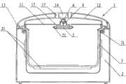
如图1所示,一种微压锅具,包括锅盖1、锅体2、内锅3和加热器21,其中所述锅体2是所述微压锅具的主要承载部,其内设置内锅2、加热器21及所述微压锅具的电控系统,所述锅盖1位于所述锅体2的上部并与所述内锅2之间设置有内锅密封圈31,在所述锅盖1上设置有信号开关4。As shown in Figure 1, a kind of micro-pressure cooker, comprises pot cover 1,
其中所述锅盖1包括外壳体12和内盖11,所述锅盖1通过其外壳体12与所述锅体2之间设置的铰接装置13铰接连接起来可以翻动。所述内锅3设置在所述锅体2内,所述内锅3的外围(侧部或/和底部)设置有加热器21,所述加热器21可以贴合在所述内锅3的外表,也可以在所述锅体2内设置了外锅的情况下贴合在外锅的外表面上。所述加热器21与所述微压锅具的控制系统电连接。The pot cover 1 includes an
所述锅盖1的外壳体12的中央部位设置一个相对封闭的容腔14,所述容腔14内设置所述信号开关4,其中所述信号开关4为微动开关,其触头向下,所述信号开关4的电接点连接所述微压锅具的控制系统或直接电连接所述加热器21(图中未画出)。对应于所述信号开关4的下面的所述内盖11上设置第一盖孔15,在所述外壳体12上设置有出气孔17,在所述第一盖孔15中设置第一泄气阀芯5。所述第一盖孔15的内径大于所述第一泄气阀芯5的外径从而它们之间具有间隙。The central part of the
所述第一泄气阀芯5呈“I”字形的杆体状,其上部通过卡口悬挂在所述容腔14的外壁上并可以在其上上下自由滑动,在第一泄气阀芯5的内部固连有一根传动臂6,在所述第一泄气阀芯5上升时其所述传动臂6的顶端可以顶压所述信号开关4的触头。The first air
在所述第一泄气阀芯5的下部固定有第一密封圈51,所述第一密封圈51的横截面呈“U”字形,当然也可以为中空的或实心的O形。所述第一密封圈51的上表面与所述锅盖1之间也具有间隙。A
如图2所示,所述第一盖孔15的结构也可以改变为在所述第一盖孔15内设置导套16,所述导套16的上部通过与所述内盖11固连的螺母17连接在所述内盖11上。所述第一泄气阀芯5设置在所述导套16的中心孔160内并且所述第一泄气阀芯5的外径小于所述导套16的中心孔160的内径。As shown in Figure 2, the structure of the
根据上述技术方案,合理确定所述第一泄气阀芯5的重量、所述第一密封圈51的重量及其底面积,就可以确定所述第一泄气阀芯5在所述内锅3内压力的驱动下的推动力,所述内锅3内的蒸汽压强在所述第一泄气阀芯5的下表面形成的推力仅仅只需克服所述第一泄气阀芯5的重量及所述传动臂6的压力就可以将所述第一盖孔15封闭并使所述加热器21停止工作。在本装置未工作前需要所述锅盖1合盖时,所述第一密封圈51的上表面与所述锅盖1之间的间隙可以排出锅内的因合盖而形成的正压空气而顺利合盖,当然也可以在快速开启所述锅盖1时消除所述内锅3容腔内的负压,使开盖变得顺利;当所述加热器21将锅内的食物进行加热的过程中,食物及水中积聚的空气会首先溢出,这些溢出的冷空气也可以顺着所述第一泄气阀芯5、所述第一密封圈与所述锅盖1之间的间隙排出,而不会使所述第一泄气阀芯5上移,防止所述信号开关4在水温达到沸点前误动作。当所述加热器21将锅内的食物予以加热到接近水的沸点时,由于水在一个标准大气压环境下从液态变为汽态体积膨胀约1600倍,也即锅内首先达到沸点的少量水汽化后立即将锅内空间的压强提高并推动所述第一泄气阀芯5上移,随之所述第一密封圈51也封闭所述第一盖孔15。此时虽然仍然有部分水会汽化但所述第一泄气阀芯5上升后也立即触动所述信号开关4切断所述加热器21,使水的汽化过程停止下来,从而使锅内的温度不会明显地、整体地超过沸点。当锅内的水及汽体温度下降压力也会随之降低,所述第一泄气阀芯5下移复位,所述信号开关4接通所述加热器21再次开始加热,如此循环。由此可以看出,锅内的汽体排出量非常少,从而使热量散发也少;其次相对于驱动整个所述锅盖1或所述内盖11移动来说,所述第一泄气阀芯5的动作可以更加灵敏。According to the above technical solution, the weight of the first air
实施例二Embodiment two
如图3所示,与实施例一不同的是,所述第一泄气阀芯5呈T字形并悬挂在所述第一盖孔15内,所述信号开关4不是位于所述第一泄气阀芯5的上面而是偏移一定距离,所述传动臂6横向设置并在所述传动臂6的中间位置设置支点61,并且所述支点61与所述传动臂6之间设置密封器件,这样从锅内排出的蒸汽不会进入所述信号开关4所在的区域,保护所述信号开关4的使用安全性。其次在所述支点61的右侧设置复位弹簧63,所述复位弹簧63的一端固连在所述锅盖1上,另一端连接在所述传动臂6,从而所述复位弹簧63不仅可以增加传动臂6的转动力,而且又可以对所述传动臂6予以定位防止其晃动。As shown in Figure 3, different from Embodiment 1, the first air
实施例三Embodiment three
如图4所示,与实施例二不同的是,所述信号开关4设置在所述锅体2的上部,在所述信号开关4与所述传动臂6之间设置有避水罩7;如图5所示,所述避水罩7呈山字形,其中所述避水罩7的两侧臂72上设置有倒钩73并可上下移动地卡接在所述锅体2的外壁上,所述避水罩7的中间臂体71顶压在所述信号开关4的按钮上;所述避水罩7的两侧臂72的外侧设置有环形壁73,所述锅体2上设置有与所述环形壁73适配的竖立壁22,所述竖立壁22插入所述环形壁73中。这样所述避水罩7可以在所述竖立壁22上滑动但不会脱出,外部的污染物也不会进入到所述锅体2内;其次所述信号开关4的信号线也可以不用连接到所述锅盖1上。另外还可以在所述竖立壁22与所述避水罩7之间也设置复位用的弹簧(图中未画出),防止所述避水罩7的自重导致所述信号开关4误动作,又可以协助所述传动臂6复位。As shown in Figure 4, the difference from the second embodiment is that the
实施例四Embodiment four
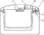
如图6所示,与实施例一不同的是,在所述内盖11上设置第二盖孔16,所述第二盖孔16中设置可以上下活动的第二泄气阀芯8;如图7所示,所述第二泄气阀芯8呈倒T字形,所述第二泄气阀芯8的杆体上部设置第二密封圈81,而所述第二盖孔16的周边卷曲起来形成卷边110,所述第二密封圈81的下表面压在所述卷边110上,这样不仅增强了所述第二盖孔16的结构强度,也能使所述第二密封圈81的下表面与所述卷边110之间形成良好的密封效果;作为一种等同的实施方案,所述第一盖孔15也可以做成与所述第二盖孔16同样的结构,不同的在于所述第一盖孔15的周边向下卷曲。其次所述第二泄气阀芯8的杆体下部设置凸出边82,在所述凸出边82的上表面设置小凸点83,这样当所述第二泄气阀芯8上移时,所述第二密封圈8可以开启所述第二盖孔16,当所述第二泄气阀芯8上移后,所述第二泄气阀芯8的下部凸出边82与所述内盖11之间仍然存在泄气的间隙。根据该结构,所述第二泄气阀芯8可以缓解快速盒盖而导致内锅3内的聚增正气压;其次在所述内锅3受热增压而使所述第一泄气阀芯5关闭后,所述内锅3内压力继续上升,则开启所述第二泄气阀芯8,确保所述微压锅具的使用安全。As shown in Figure 6, the difference from Embodiment 1 is that a
实际上,所述第二泄气阀芯8的结构与所述第一泄气阀芯5的结构基本相同,不同的是它们各自的密封圈设置的位置颠倒,并且它们可以承受的压强大小不一致,很显然将所述第二泄气阀芯8承受锅内压强的能力设置得大一些,即在所述内锅3压力上升过程中,所述第一泄气阀芯5首先上移,只有当所述内锅3内的压力继续上升到一个更大的压力值时,所述第二泄气阀芯8才往上移,释放所述内锅3内的高压蒸汽,防止过高的蒸汽损坏所述内锅3、内锅密封圈31或锅盖1。In fact, the structure of the
实施例五Embodiment five
如图8所示,与实施例一和实施例三不同的是,所述信号开关4设置所述内盖11的上部但位于所述第一泄气阀芯5的侧边位置,所述信号开关4的上面设置避水罩7,在所述内盖11上设置与所述避水罩7适配的竖立壁,所述避水罩7可滑动地插接在所述竖立壁上。所述第一泄气阀芯5呈T字形并悬挂在所述内盖11上,其中所述第一泄气阀芯5的上部凸出边53压在所述避水罩7上,因此所述凸出边53等同于上面实施例中的所述传动臂6。其次在所述第一泄气阀芯5的中心位置设置有通孔52,在所述通孔52中设置第二泄气阀芯8。而所述第二泄气阀芯8的结构和功能又与实施例四是相同的。As shown in Fig. 8, different from Embodiment 1 and
实施例六Embodiment six
如图9所示,与实施例五之间的主要不同点在于所述信号开关4设置在所述锅体2的上部,所述传动臂6的前端具有叉口62从而为所述第二泄气阀芯8提供避空的空间。As shown in Figure 9, the main difference from
实施例七Embodiment seven
如图10所示,与实施例六之间的主要不同点在于,所述第一泄气阀芯5与所述第二泄气阀芯8的位置调换过来,即将所述第二泄气阀芯8设置在所述第一盖孔15内,在所述第二泄气阀芯8的中心孔中设置所述第一泄气阀芯5。但锅内压力升高时,所述第一泄气阀芯5首先上移驱动所述传动臂6转动,如果锅内的气压继续上升,在再次开启所述第二泄气阀芯8,释放高压气体。As shown in Figure 10, the main difference from
实施例八Embodiment Eight
如图11所示,与实施例四之间的主要不同点在于,在所述第一泄气阀芯5与所述信号开关4的支撑臂之间设置复位弹簧63,在所述第二泄气阀芯8与所述外壳体12之间设置限压弹簧9。其中所述复位弹簧63不仅其复位作用,而且也起限压作用,等同与所述限压弹簧9的功能。所述复位弹簧63和调压弹簧9不仅可以调节所述第一泄气阀芯5和所述第二泄气阀芯8上移所需的压力,也可以帮助所述第一泄气阀芯5和所述第二泄气阀芯8及早下移从而使所述信号开关4及早复位,防止所述内锅3内的温度过低。As shown in Figure 11, the main difference from
Claims (7)
Translated fromChinesePriority Applications (1)
| Application Number | Priority Date | Filing Date | Title |
|---|---|---|---|
| CN 201110071153CN102178443B (en) | 2011-03-23 | 2011-03-23 | Micro-pressure cooker |
Applications Claiming Priority (1)
| Application Number | Priority Date | Filing Date | Title |
|---|---|---|---|
| CN 201110071153CN102178443B (en) | 2011-03-23 | 2011-03-23 | Micro-pressure cooker |
Related Child Applications (1)
| Application Number | Title | Priority Date | Filing Date |
|---|---|---|---|
| CN2011101534479ADivisionCN102240165A (en) | 2011-03-23 | 2011-03-23 | Micropressure boiler |
Publications (2)
| Publication Number | Publication Date |
|---|---|
| CN102178443A CN102178443A (en) | 2011-09-14 |
| CN102178443Btrue CN102178443B (en) | 2013-08-14 |
Family
ID=44564860
Family Applications (1)
| Application Number | Title | Priority Date | Filing Date |
|---|---|---|---|
| CN 201110071153ActiveCN102178443B (en) | 2011-03-23 | 2011-03-23 | Micro-pressure cooker |
Country Status (1)
| Country | Link |
|---|---|
| CN (1) | CN102178443B (en) |
Families Citing this family (12)
| Publication number | Priority date | Publication date | Assignee | Title |
|---|---|---|---|---|
| CN102987921B (en)* | 2012-12-14 | 2015-10-28 | 深圳市北鼎晶辉科技股份有限公司 | Tea machine |
| CN103211514B (en)* | 2013-05-13 | 2016-08-10 | 浙江苏泊尔家电制造有限公司 | Electric cooker |
| WO2019032876A1 (en) | 2017-08-09 | 2019-02-14 | Sharkninja Operating Llc | Cooking device and components thereof |
| CN109549501B (en)* | 2017-09-25 | 2023-10-24 | 佛山市顺德区美的电热电器制造有限公司 | Steam valve assembly and cooking utensil |
| WO2019114215A1 (en)* | 2017-12-12 | 2019-06-20 | 佛山市顺德区美的电热电器制造有限公司 | Steam valve, cover plate assembly, electric cooking appliance and power control method therefor |
| US11051654B2 (en) | 2019-02-25 | 2021-07-06 | Sharkninja Operating Llc | Cooking device and components thereof |
| WO2020176477A1 (en) | 2019-02-25 | 2020-09-03 | Sharkninja Operating Llc | Cooking system with guard |
| CN113116121B (en)* | 2019-12-31 | 2022-07-29 | 浙江苏泊尔家电制造有限公司 | Cooking appliance, cooking method, and computer storage medium |
| US11678765B2 (en) | 2020-03-30 | 2023-06-20 | Sharkninja Operating Llc | Cooking device and components thereof |
| CN112493868B (en)* | 2020-12-01 | 2024-09-27 | 珠海格力电器股份有限公司 | Steam valve, cooking utensil and control method |
| CN112586993A (en)* | 2020-12-23 | 2021-04-02 | 珠海格力电器股份有限公司 | Cooking utensil's lid structure and cooking utensil |
| CN115325209B (en)* | 2022-07-26 | 2025-04-01 | 湖南友风新材料科技有限公司 | Directional valve |
Citations (2)
| Publication number | Priority date | Publication date | Assignee | Title |
|---|---|---|---|---|
| CN2086562U (en)* | 1990-08-01 | 1991-10-16 | 王永光 | Full-sealed automatic pressure cooker |
| CN2317777Y (en)* | 1997-09-29 | 1999-05-12 | 王志强 | Explosion-proof device for pressure cooker |
Family Cites Families (3)
| Publication number | Priority date | Publication date | Assignee | Title |
|---|---|---|---|---|
| FR2827493B1 (en)* | 2001-07-20 | 2005-08-05 | Seb Sa | AUTOCUISEUR COMPRISING A CALIBER LEAKAGE MEANS |
| JP3403086B2 (en)* | 1998-08-27 | 2003-05-06 | 三洋電機株式会社 | Electric rice cooker |
| CN2781971Y (en)* | 2005-04-13 | 2006-05-24 | 杨达开 | Automatic electrical pressure cooker |
- 2011
- 2011-03-23CNCN 201110071153patent/CN102178443B/enactiveActive
Patent Citations (2)
| Publication number | Priority date | Publication date | Assignee | Title |
|---|---|---|---|---|
| CN2086562U (en)* | 1990-08-01 | 1991-10-16 | 王永光 | Full-sealed automatic pressure cooker |
| CN2317777Y (en)* | 1997-09-29 | 1999-05-12 | 王志强 | Explosion-proof device for pressure cooker |
Also Published As
| Publication number | Publication date |
|---|---|
| CN102178443A (en) | 2011-09-14 |
Similar Documents
| Publication | Publication Date | Title |
|---|---|---|
| CN102178443B (en) | Micro-pressure cooker | |
| CN102204782A (en) | Movable-cover-type micropressure cooker | |
| CN100401957C (en) | Electric pressure cooker with precise pressure control | |
| KR101220087B1 (en) | Eco green cookware | |
| JP6017493B2 (en) | Eco cookware | |
| CN105433779B (en) | A kind of pressure relief device and its pressure cooker | |
| CN105054772A (en) | Electric pressure cooker with air exhaust function and air exhaust control method | |
| CN203016735U (en) | Frying and roasting machine with frying and roasting cavity adjustable in height | |
| CN110742491B (en) | Anti-overflow and anti-scald electric cooker | |
| CN104887066B (en) | A kind of electric pressure cooking saucepan of band pumping | |
| RU2711944C2 (en) | Double reservoir for food preparation, having improved strength and improved thermal coefficient of efficiency | |
| CN204909047U (en) | An electric pressure cooker with suction | |
| CN102240165A (en) | Micropressure boiler | |
| CN205053829U (en) | Electrical heating cup | |
| CN202355232U (en) | Pot lid with bimetal pressure relief valve | |
| CN206166615U (en) | Wiper seal gai di of easy pressure release | |
| CN209463837U (en) | An intelligent pressure control pressure cooker | |
| CN201542414U (en) | Automatic air obstructer of pressure cooker | |
| CN202051512U (en) | Movable cover type micro-pressure cooker | |
| CN204427784U (en) | Steam valve and cooking apparatus | |
| CN204734332U (en) | Electric pressure cooker who bled in area | |
| CN203723875U (en) | Heater with air-pressure-type electric control switch | |
| CN204427668U (en) | A kind of kettle | |
| CN201356429Y (en) | Flour cover of cooking device | |
| CN1369247A (en) | pressure cooker |
Legal Events
| Date | Code | Title | Description |
|---|---|---|---|
| C06 | Publication | ||
| PB01 | Publication | ||
| C10 | Entry into substantive examination | ||
| SE01 | Entry into force of request for substantive examination | ||
| C14 | Grant of patent or utility model | ||
| GR01 | Patent grant | ||
| C56 | Change in the name or address of the patentee | ||
| CP03 | Change of name, title or address | Address after:528200 Foshan, China, Nanhai District, Songgang Industrial Park, Industrial Park Road West Patentee after:DEA GENERAL AVIATION HOLDING Co.,Ltd. Address before:528231 Industrial Avenue, Songgang Pine Industrial Park, Nanhai District, Guangdong, Foshan Patentee before:Guangdong Elecpro Electric Appliance Holding Co.,Ltd. | |
| CP01 | Change in the name or title of a patent holder | ||
| CP01 | Change in the name or title of a patent holder | Address after:528200 Industrial Avenue, Songgang Pine Industrial Park, Nanhai District, Guangdong, Foshan Patentee after:Yilipu Group Co.,Ltd. Address before:528200 Industrial Avenue, Songgang Pine Industrial Park, Nanhai District, Guangdong, Foshan Patentee before:DEA GENERAL AVIATION HOLDING Co.,Ltd. |