CN102177439B - Microfluidic device using centrifugal force and sample analysis method using the same - Google Patents
Microfluidic device using centrifugal force and sample analysis method using the sameDownload PDFInfo
- Publication number
- CN102177439B CN102177439BCN2009801401798ACN200980140179ACN102177439BCN 102177439 BCN102177439 BCN 102177439BCN 2009801401798 ACN2009801401798 ACN 2009801401798ACN 200980140179 ACN200980140179 ACN 200980140179ACN 102177439 BCN102177439 BCN 102177439B
- Authority
- CN
- China
- Prior art keywords
- sample
- chamber
- supernatant
- microfluidic device
- concentration
- Prior art date
- Legal status (The legal status is an assumption and is not a legal conclusion. Google has not performed a legal analysis and makes no representation as to the accuracy of the status listed.)
- Active
Links
Images


Classifications
- G—PHYSICS
- G01—MEASURING; TESTING
- G01N—INVESTIGATING OR ANALYSING MATERIALS BY DETERMINING THEIR CHEMICAL OR PHYSICAL PROPERTIES
- G01N35/00—Automatic analysis not limited to methods or materials provided for in any single one of groups G01N1/00 - G01N33/00; Handling materials therefor
- B—PERFORMING OPERATIONS; TRANSPORTING
- B32—LAYERED PRODUCTS
- B32B—LAYERED PRODUCTS, i.e. PRODUCTS BUILT-UP OF STRATA OF FLAT OR NON-FLAT, e.g. CELLULAR OR HONEYCOMB, FORM
- B32B37/00—Methods or apparatus for laminating, e.g. by curing or by ultrasonic bonding
- B32B37/12—Methods or apparatus for laminating, e.g. by curing or by ultrasonic bonding characterised by using adhesives
- B—PERFORMING OPERATIONS; TRANSPORTING
- B01—PHYSICAL OR CHEMICAL PROCESSES OR APPARATUS IN GENERAL
- B01L—CHEMICAL OR PHYSICAL LABORATORY APPARATUS FOR GENERAL USE
- B01L3/00—Containers or dishes for laboratory use, e.g. laboratory glassware; Droppers
- B01L3/50—Containers for the purpose of retaining a material to be analysed, e.g. test tubes
- B01L3/502—Containers for the purpose of retaining a material to be analysed, e.g. test tubes with fluid transport, e.g. in multi-compartment structures
- B01L3/5027—Containers for the purpose of retaining a material to be analysed, e.g. test tubes with fluid transport, e.g. in multi-compartment structures by integrated microfluidic structures, i.e. dimensions of channels and chambers are such that surface tension forces are important, e.g. lab-on-a-chip
- B—PERFORMING OPERATIONS; TRANSPORTING
- B07—SEPARATING SOLIDS FROM SOLIDS; SORTING
- B07C—POSTAL SORTING; SORTING INDIVIDUAL ARTICLES, OR BULK MATERIAL FIT TO BE SORTED PIECE-MEAL, e.g. BY PICKING
- B07C5/00—Sorting according to a characteristic or feature of the articles or material being sorted, e.g. by control effected by devices which detect or measure such characteristic or feature; Sorting by manually actuated devices, e.g. switches
- B07C5/34—Sorting according to other particular properties
- B07C5/3416—Sorting according to other particular properties according to radiation transmissivity, e.g. for light, x-rays, particle radiation
- G—PHYSICS
- G01—MEASURING; TESTING
- G01N—INVESTIGATING OR ANALYSING MATERIALS BY DETERMINING THEIR CHEMICAL OR PHYSICAL PROPERTIES
- G01N21/00—Investigating or analysing materials by the use of optical means, i.e. using sub-millimetre waves, infrared, visible or ultraviolet light
- G01N21/17—Systems in which incident light is modified in accordance with the properties of the material investigated
- G01N21/25—Colour; Spectral properties, i.e. comparison of effect of material on the light at two or more different wavelengths or wavelength bands
- B—PERFORMING OPERATIONS; TRANSPORTING
- B01—PHYSICAL OR CHEMICAL PROCESSES OR APPARATUS IN GENERAL
- B01L—CHEMICAL OR PHYSICAL LABORATORY APPARATUS FOR GENERAL USE
- B01L2200/00—Solutions for specific problems relating to chemical or physical laboratory apparatus
- B01L2200/06—Fluid handling related problems
- B01L2200/0605—Metering of fluids
- B—PERFORMING OPERATIONS; TRANSPORTING
- B01—PHYSICAL OR CHEMICAL PROCESSES OR APPARATUS IN GENERAL
- B01L—CHEMICAL OR PHYSICAL LABORATORY APPARATUS FOR GENERAL USE
- B01L2200/00—Solutions for specific problems relating to chemical or physical laboratory apparatus
- B01L2200/14—Process control and prevention of errors
- B01L2200/143—Quality control, feedback systems
- B—PERFORMING OPERATIONS; TRANSPORTING
- B01—PHYSICAL OR CHEMICAL PROCESSES OR APPARATUS IN GENERAL
- B01L—CHEMICAL OR PHYSICAL LABORATORY APPARATUS FOR GENERAL USE
- B01L2300/00—Additional constructional details
- B01L2300/06—Auxiliary integrated devices, integrated components
- B01L2300/0627—Sensor or part of a sensor is integrated
- B01L2300/0654—Lenses; Optical fibres
- B—PERFORMING OPERATIONS; TRANSPORTING
- B01—PHYSICAL OR CHEMICAL PROCESSES OR APPARATUS IN GENERAL
- B01L—CHEMICAL OR PHYSICAL LABORATORY APPARATUS FOR GENERAL USE
- B01L2300/00—Additional constructional details
- B01L2300/08—Geometry, shape and general structure
- B01L2300/0803—Disc shape
- B—PERFORMING OPERATIONS; TRANSPORTING
- B01—PHYSICAL OR CHEMICAL PROCESSES OR APPARATUS IN GENERAL
- B01L—CHEMICAL OR PHYSICAL LABORATORY APPARATUS FOR GENERAL USE
- B01L2300/00—Additional constructional details
- B01L2300/08—Geometry, shape and general structure
- B01L2300/0861—Configuration of multiple channels and/or chambers in a single devices
- B01L2300/0864—Configuration of multiple channels and/or chambers in a single devices comprising only one inlet and multiple receiving wells, e.g. for separation, splitting
- B—PERFORMING OPERATIONS; TRANSPORTING
- B01—PHYSICAL OR CHEMICAL PROCESSES OR APPARATUS IN GENERAL
- B01L—CHEMICAL OR PHYSICAL LABORATORY APPARATUS FOR GENERAL USE
- B01L2300/00—Additional constructional details
- B01L2300/08—Geometry, shape and general structure
- B01L2300/0861—Configuration of multiple channels and/or chambers in a single devices
- B01L2300/0867—Multiple inlets and one sample wells, e.g. mixing, dilution
- B—PERFORMING OPERATIONS; TRANSPORTING
- B01—PHYSICAL OR CHEMICAL PROCESSES OR APPARATUS IN GENERAL
- B01L—CHEMICAL OR PHYSICAL LABORATORY APPARATUS FOR GENERAL USE
- B01L2300/00—Additional constructional details
- B01L2300/08—Geometry, shape and general structure
- B01L2300/0861—Configuration of multiple channels and/or chambers in a single devices
- B01L2300/087—Multiple sequential chambers
- B—PERFORMING OPERATIONS; TRANSPORTING
- B01—PHYSICAL OR CHEMICAL PROCESSES OR APPARATUS IN GENERAL
- B01L—CHEMICAL OR PHYSICAL LABORATORY APPARATUS FOR GENERAL USE
- B01L2400/00—Moving or stopping fluids
- B01L2400/04—Moving fluids with specific forces or mechanical means
- B01L2400/0403—Moving fluids with specific forces or mechanical means specific forces
- B01L2400/0409—Moving fluids with specific forces or mechanical means specific forces centrifugal forces
- B—PERFORMING OPERATIONS; TRANSPORTING
- B01—PHYSICAL OR CHEMICAL PROCESSES OR APPARATUS IN GENERAL
- B01L—CHEMICAL OR PHYSICAL LABORATORY APPARATUS FOR GENERAL USE
- B01L2400/00—Moving or stopping fluids
- B01L2400/06—Valves, specific forms thereof
- B01L2400/0677—Valves, specific forms thereof phase change valves; Meltable, freezing, dissolvable plugs; Destructible barriers
- B—PERFORMING OPERATIONS; TRANSPORTING
- B32—LAYERED PRODUCTS
- B32B—LAYERED PRODUCTS, i.e. PRODUCTS BUILT-UP OF STRATA OF FLAT OR NON-FLAT, e.g. CELLULAR OR HONEYCOMB, FORM
- B32B37/00—Methods or apparatus for laminating, e.g. by curing or by ultrasonic bonding
- B32B37/12—Methods or apparatus for laminating, e.g. by curing or by ultrasonic bonding characterised by using adhesives
- B32B2037/1253—Methods or apparatus for laminating, e.g. by curing or by ultrasonic bonding characterised by using adhesives curable adhesive
- B—PERFORMING OPERATIONS; TRANSPORTING
- B32—LAYERED PRODUCTS
- B32B—LAYERED PRODUCTS, i.e. PRODUCTS BUILT-UP OF STRATA OF FLAT OR NON-FLAT, e.g. CELLULAR OR HONEYCOMB, FORM
- B32B2310/00—Treatment by energy or chemical effects
- B32B2310/08—Treatment by energy or chemical effects by wave energy or particle radiation
- B32B2310/0806—Treatment by energy or chemical effects by wave energy or particle radiation using electromagnetic radiation
- B—PERFORMING OPERATIONS; TRANSPORTING
- B32—LAYERED PRODUCTS
- B32B—LAYERED PRODUCTS, i.e. PRODUCTS BUILT-UP OF STRATA OF FLAT OR NON-FLAT, e.g. CELLULAR OR HONEYCOMB, FORM
- B32B2535/00—Medical equipment, e.g. bandage, prostheses or catheter
- G—PHYSICS
- G01—MEASURING; TESTING
- G01N—INVESTIGATING OR ANALYSING MATERIALS BY DETERMINING THEIR CHEMICAL OR PHYSICAL PROPERTIES
- G01N21/00—Investigating or analysing materials by the use of optical means, i.e. using sub-millimetre waves, infrared, visible or ultraviolet light
- G01N21/01—Arrangements or apparatus for facilitating the optical investigation
- G01N21/03—Cuvette constructions
- G01N2021/0325—Cells for testing reactions, e.g. containing reagents
- G—PHYSICS
- G01—MEASURING; TESTING
- G01N—INVESTIGATING OR ANALYSING MATERIALS BY DETERMINING THEIR CHEMICAL OR PHYSICAL PROPERTIES
- G01N21/00—Investigating or analysing materials by the use of optical means, i.e. using sub-millimetre waves, infrared, visible or ultraviolet light
- G01N21/01—Arrangements or apparatus for facilitating the optical investigation
- G01N21/03—Cuvette constructions
- G01N21/07—Centrifugal type cuvettes
- G—PHYSICS
- G01—MEASURING; TESTING
- G01N—INVESTIGATING OR ANALYSING MATERIALS BY DETERMINING THEIR CHEMICAL OR PHYSICAL PROPERTIES
- G01N21/00—Investigating or analysing materials by the use of optical means, i.e. using sub-millimetre waves, infrared, visible or ultraviolet light
- G01N21/75—Systems in which material is subjected to a chemical reaction, the progress or the result of the reaction being investigated
- G01N21/77—Systems in which material is subjected to a chemical reaction, the progress or the result of the reaction being investigated by observing the effect on a chemical indicator
- G01N21/78—Systems in which material is subjected to a chemical reaction, the progress or the result of the reaction being investigated by observing the effect on a chemical indicator producing a change of colour
- G01N21/81—Indicating humidity
- Y—GENERAL TAGGING OF NEW TECHNOLOGICAL DEVELOPMENTS; GENERAL TAGGING OF CROSS-SECTIONAL TECHNOLOGIES SPANNING OVER SEVERAL SECTIONS OF THE IPC; TECHNICAL SUBJECTS COVERED BY FORMER USPC CROSS-REFERENCE ART COLLECTIONS [XRACs] AND DIGESTS
- Y10—TECHNICAL SUBJECTS COVERED BY FORMER USPC
- Y10T—TECHNICAL SUBJECTS COVERED BY FORMER US CLASSIFICATION
- Y10T156/00—Adhesive bonding and miscellaneous chemical manufacture
- Y10T156/10—Methods of surface bonding and/or assembly therefor
- Y—GENERAL TAGGING OF NEW TECHNOLOGICAL DEVELOPMENTS; GENERAL TAGGING OF CROSS-SECTIONAL TECHNOLOGIES SPANNING OVER SEVERAL SECTIONS OF THE IPC; TECHNICAL SUBJECTS COVERED BY FORMER USPC CROSS-REFERENCE ART COLLECTIONS [XRACs] AND DIGESTS
- Y10—TECHNICAL SUBJECTS COVERED BY FORMER USPC
- Y10T—TECHNICAL SUBJECTS COVERED BY FORMER US CLASSIFICATION
- Y10T436/00—Chemistry: analytical and immunological testing
- Y10T436/21—Hydrocarbon
- Y10T436/214—Acyclic [e.g., methane, octane, isoparaffin, etc.]
- Y—GENERAL TAGGING OF NEW TECHNOLOGICAL DEVELOPMENTS; GENERAL TAGGING OF CROSS-SECTIONAL TECHNOLOGIES SPANNING OVER SEVERAL SECTIONS OF THE IPC; TECHNICAL SUBJECTS COVERED BY FORMER USPC CROSS-REFERENCE ART COLLECTIONS [XRACs] AND DIGESTS
- Y10—TECHNICAL SUBJECTS COVERED BY FORMER USPC
- Y10T—TECHNICAL SUBJECTS COVERED BY FORMER US CLASSIFICATION
- Y10T436/00—Chemistry: analytical and immunological testing
- Y10T436/25—Chemistry: analytical and immunological testing including sample preparation
- Y10T436/2575—Volumetric liquid transfer
Landscapes
- Health & Medical Sciences (AREA)
- Chemical & Material Sciences (AREA)
- General Health & Medical Sciences (AREA)
- Analytical Chemistry (AREA)
- Physics & Mathematics (AREA)
- Life Sciences & Earth Sciences (AREA)
- General Physics & Mathematics (AREA)
- Clinical Laboratory Science (AREA)
- Chemical Kinetics & Catalysis (AREA)
- Dispersion Chemistry (AREA)
- Toxicology (AREA)
- Biochemistry (AREA)
- Hematology (AREA)
- Immunology (AREA)
- Pathology (AREA)
- Spectroscopy & Molecular Physics (AREA)
- Automatic Analysis And Handling Materials Therefor (AREA)
- Investigating Or Analysing Materials By Optical Means (AREA)
- Optical Measuring Cells (AREA)
- Investigating Or Analyzing Non-Biological Materials By The Use Of Chemical Means (AREA)
Abstract
Translated fromChinese
Description
Translated fromChinese技术领域technical field
一个或多个实施例涉及一种利用离心力的微流体装置以及一种使用所述微流装置分析样品的方法。One or more embodiments relate to a microfluidic device using centrifugal force and a method of analyzing a sample using the microfluidic device.
背景技术Background technique
微流体装置的微流体结构的示例包括可容纳少量流体的室、流体可流过的通道、可调节流体流动的阀、可容纳流体并执行预定功能的各种功能单元。将微流体装置的微流体结构安装在其上以执行包括生化反应的各种测试的小芯片被称为生物芯片,更具体地说,形成为在一个芯片上执行各种操作的装置被称为实验室芯片(lab-on-a-chip)。Examples of microfluidic structures of microfluidic devices include chambers that can hold a small amount of fluid, channels through which fluid can flow, valves that can regulate fluid flow, various functional units that can hold fluid and perform predetermined functions. Small chips on which microfluidic structures of microfluidic devices are mounted to perform various tests including biochemical reactions are called biochips, and more specifically, devices formed to perform various operations on one chip are called Lab-on-a-chip.
需要驱动压力以在微流体装置的微流体结构内传送流体,毛细管压力或者由泵提供的压力被用作驱动压力。近来,已提出通过将微流体结构安装在盘形平台中而使用离心力的微流体装置。这些装置被称为实验室盘或实验室CD。Driving pressure is required to transfer fluids within the microfluidic structures of the microfluidic device, and capillary pressure or pressure provided by a pump is used as the driving pressure. Recently, microfluidic devices using centrifugal force by mounting microfluidic structures in disc-shaped platforms have been proposed. These devices are known as lab disks or lab CDs.
发明内容Contents of the invention
技术问题technical problem
一个或多个实施例包括一种利用离心力的微流体装置,所述微流体装置测量试剂与样品的反应物材料的吸光率,以分析样品的成分。One or more embodiments include a microfluidic device utilizing centrifugal force that measures the absorbance of reactant materials of a reagent and a sample to analyze components of the sample.
一个或多个实施例包括一种方法,所述方法通过使用粘合剂将多个层结合来制造利用离心力的微流体装置。One or more embodiments include a method of fabricating a microfluidic device utilizing centrifugal force by bonding multiple layers using an adhesive.
一个或多个实施例包括一种方法,所述方法通过使用利用离心力的微流体装置使样品与试剂反应来分析样品,所述方法测量反应物材料的吸光率并检测样品的成分。One or more embodiments include a method of analyzing a sample by reacting the sample with a reagent using a microfluidic device utilizing centrifugal force, the method measuring absorbance of a reactant material and detecting components of the sample.
其他方面和/或优点一部分将在下面的描述中进行阐述,部分将通过描述而清楚或可通过本发明的实践而了解。Other aspects and/or advantages will be set forth in part in the description which follows, and part will be apparent from the description, or can be learned by practice of the invention.
技术方案Technical solutions
为了获得以上和/或其他方面和优点,一个或多个实施例可包括一种微流体装置,该微流体装置包括:样品室;至少一个分析单元,容纳来自样品室的样品,并根据样品和试剂之间的反应检测包含在样品中的成分;变性检测室,确定微流体装置的储藏状态,其中,变性检测室容纳有吸光率根据变性检测室的温度和/或含水量而变化的材料。To achieve the above and/or other aspects and advantages, one or more embodiments may include a microfluidic device comprising: a sample chamber; at least one analysis unit containing a sample from the sample chamber, and A reaction between the reagents detects components contained in the sample; a denaturation detection chamber to determine the storage state of the microfluidic device, wherein the denaturation detection chamber contains a material whose absorbance changes according to the temperature and/or water content of the denaturation detection chamber.
所述至少一个分析单元可包括:样品分配单元,连接到样品室,并从样品分离出上清液;上清液计量室,具有用于计量从样品分配单元供应的上清液的容积;稀释液室,连接到上清液计量室,其中,稀释液室容纳用于稀释上清液的稀释液;多个反应室,通过分配通道连接到稀释液室,以容纳样品稀释液,其中,所述多个反应室容纳有试剂。The at least one analysis unit may include: a sample distribution unit connected to the sample chamber and separating a supernatant from the sample; a supernatant metering chamber having a volume for metering the supernatant supplied from the sample distribution unit; a liquid chamber connected to the supernatant metering chamber, wherein the diluent chamber contains a diluent for diluting the supernatant; a plurality of reaction chambers are connected to the diluent chamber through distribution channels to accommodate the sample diluent, wherein the The plurality of reaction chambers contain reagents.
微流体装置还可包括使用前检测室,以通过测量使用前检测室的吸光率来确定微流体装置以前是否使用过,其中,使用前检测室设置在样品分配单元的端部。The microfluidic device may further include a pre-use detection chamber to determine whether the microfluidic device has been used before by measuring an absorbance of the pre-use detection chamber, wherein the pre-use detection chamber is disposed at an end of the sample dispensing unit.
微流体装置还可包括过量样品室,以通过测量过量样品室的吸光率来确定样品的量,过量样品室容纳超过样品分配单元的容积的过量样品。The microfluidic device may also include an excess sample chamber to determine the amount of sample by measuring the absorbance of the excess sample chamber, the excess sample chamber containing excess sample exceeding the volume of the sample dispensing unit.
微流体装置还可包括上清液检测室,以通过测量上清液检测室的吸光率来确定上清液的状态。上清液检测室连接到将上清液计量室与样品分配单元连接的通道,以容纳上清液。The microfluidic device may further include a supernatant detection chamber to determine the state of the supernatant by measuring the absorbance of the supernatant detection chamber. The supernatant detection chamber is connected to the channel connecting the supernatant metering chamber with the sample dispensing unit to contain the supernatant.
微流体装置还可包括过量上清液室,过量上清液室连接到将上清液计量室和样品分配单元连接的通道,并容纳超过上清液计量室的容积的过量上清液。The microfluidic device may further include an excess supernatant chamber connected to the channel connecting the supernatant metering chamber and the sample dispensing unit and containing excess supernatant exceeding a volume of the supernatant metering chamber.
微流体装置还可包括至少一个第一浓度确定室,第一浓度确定室通过测量第一浓度确定室的吸光率来提供用于检测样品稀释液的浓度的参考值,并容纳来自样品分配单元的上清液。微流体装置可包括至少两个第一浓度确定室,其中,所述至少两个第一浓度确定室的深度不同。The microfluidic device may further include at least one first concentration determination chamber, which provides a reference value for detecting the concentration of the sample diluent by measuring the absorbance of the first concentration determination chamber, and accommodates supernatant. The microfluidic device may comprise at least two first concentration-determining chambers, wherein the at least two first concentration-determining chambers have different depths.
微流体装置还可包括第二浓度确定室,第二浓度确定室容纳来自稀释液室的样品稀释液并连接到分配通道,以先于所述多个反应室容纳样品稀释液,其中,第二浓度确定室是从稀释液室开始的第二个室,并用于通过测量第二浓度确定室的吸光率来检测样品稀释液的浓度。The microfluidic device may further include a second concentration determining chamber containing the sample diluent from the diluent chamber and connected to the distribution channel to accommodate the sample diluent prior to the plurality of reaction chambers, wherein the second The concentration determination chamber is the second chamber from the diluent chamber, and is used to detect the concentration of the sample diluent by measuring the absorbance of the second concentration determination chamber.
微流体装置还可包括样品稀释液检测室,样品稀释液检测室容纳样品稀释液并连接到分配通道,以在所有其他反应室都容纳样品稀释液之后最后容纳样品稀释液。The microfluidic device may also include a sample diluent detection chamber containing the sample diluent and connected to the distribution channel to contain the sample diluent last after all other reaction chambers contain the sample diluent.
微流体装置还可包括温度检测室,温度检测室容纳吸光率根据温度检测室的温度而变化的材料。The microfluidic device may further include a temperature detection chamber containing a material whose absorbance changes according to the temperature of the temperature detection chamber.
微流体装置还可包括多个试剂盒,所述多个试剂盒容纳有呈冻干状态的试剂并安装在多个反应室中。The microfluidic device may further include a plurality of reagent cartridges containing reagents in a lyophilized state and installed in a plurality of reaction chambers.
微流体装置还可包括:平台,包括被结合为彼此面对的第一层和第二层;粘合剂,设置在第一层和第二层之间,以使第一层和第二层彼此结合。样品室、所述至少一个分析单元以及变性检测室可在第一层中形成为凹槽。The microfluidic device may further include: a platform including a first layer and a second layer bonded to face each other; an adhesive disposed between the first layer and the second layer so that the first layer and the second layer combined with each other. The sample chamber, the at least one analysis unit, and the denaturation detection chamber may be formed as grooves in the first layer.
可通过照射具有长波长的电磁波使粘合剂固化。可通过吸收具有大约200nm至大约900nm的波长的光使粘合剂固化。可通过吸收具有大约250nm至大约600nm的波长的光使粘合剂固化。The adhesive can be cured by irradiating electromagnetic waves having a long wavelength. The adhesive may be cured by absorbing light having a wavelength of about 200 nm to about 900 nm. The adhesive may be cured by absorbing light having a wavelength of about 250 nm to about 600 nm.
粘合剂可包括固化树脂和光聚合引发剂。光聚合引发剂可从由苯偶姻醚、苯甲酮材料、氨化材料、苯乙酮材料、噻吨酮材料、路易斯酸材料、或者这些的组合组成的组中选择。光聚合引发剂还可从由樟脑奎宁、α-萘基或苯甲基、2,4-二乙基噻吨酮、三甲基苯甲酰基二苯基氢氧化硫、甲基噻吨酮、或者这些的组合组成的组中选择。The adhesive may include a curable resin and a photopolymerization initiator. The photopolymerization initiator may be selected from the group consisting of benzoin ethers, benzophenone materials, ammoniated materials, acetophenone materials, thioxanthone materials, Lewis acid materials, or combinations of these. The photopolymerization initiator can also be made from camphorquinine, α-naphthyl or benzyl, 2,4-diethylthioxanthone, trimethylbenzoyl diphenylsulfur hydroxide, methylthioxanthone , or a combination of these.
为了获得以上和/或其他方面和优点,一个或多个实施例可包括一种制造微流体装置的方法,所述方法包括:设置第一层,第一层包括分别对应于样品室、所述至少一个分析单元以及变性检测室的凹槽;设置第二层;将粘合剂施加在第一层和/或第二层上;将第一层和第二层彼此附着;通过将光照射到粘合剂而是使粘合剂固化。In order to obtain the above and/or other aspects and advantages, one or more embodiments may include a method of manufacturing a microfluidic device, the method comprising: providing a first layer, the first layer includes respectively corresponding to the sample chamber, the at least one analysis unit and a recess of a denaturation detection chamber; providing a second layer; applying an adhesive to the first layer and/or the second layer; attaching the first layer and the second layer to each other; Instead, the adhesive cures the adhesive.
为了获得以上和/或其他方面和优点,一个或多个实施例可包括一种使用微流体装置分析包含在样品中的成分的方法,所述微流体装置包括:样品室;至少一个分析单元,容纳来自样品室的样品,并使样品和试剂反应,且测量反应物材料的吸光率以检测包含在样品中的成分,所述方法包括:将样品供应到微流体装置的样品室;将微流体装置安装在旋转驱动单元上;通过测量微流体装置的变性检测室的吸光率来确定微流体装置的储藏条件是否适合于测试,其中,吸光率根据变性检测室的温度和含水量而变化的材料容纳在变性检测室中。To achieve the above and/or other aspects and advantages, one or more embodiments may include a method of analyzing components contained in a sample using a microfluidic device comprising: a sample chamber; at least one analysis unit, receiving a sample from a sample chamber, reacting the sample with a reagent, and measuring the absorbance of the reactant material to detect components contained in the sample, the method comprising: supplying the sample to the sample chamber of the microfluidic device; The device is mounted on a rotary drive unit; the storage conditions of the microfluidic device are determined to be suitable for testing by measuring the absorbance of the denaturation detection chamber of the microfluidic device, where the absorbance varies according to the temperature and moisture content of the material in the denaturation detection chamber Housed in the denaturation detection chamber.
所述方法可包括:通过使用旋转驱动单元使微流体装置旋转产生的离心力使样品从样品室运动到样品分配单元;通过测量设置在样品分配单元的端部的使用检测室的吸光率来确定微流体装置以前是否使用过。The method may include: moving the sample from the sample chamber to the sample dispensing unit by centrifugal force generated by rotating the microfluidic device using a rotary driving unit; Whether the fluidic device has been used before.
所述方法可包括:通过使用旋转驱动单元使微流体装置旋转产生的离心力使样品从样品室运动到样品分配单元;通过测量过量样品室的吸光率来确定样品的量是否足够,过量样品室容纳超过样品分配单元的容积的过量样品。The method may include: moving the sample from the sample chamber to the sample dispensing unit by centrifugal force generated by rotating the microfluidic device using the rotary drive unit; determining whether the amount of the sample is sufficient by measuring the absorbance of the excess sample chamber containing Excess sample exceeding the volume of the sample dispense unit.
当微流体装置包括容纳来自样品室的样品的多个串联的分析单元时,超过所述多个分析单元中的最后那个分析单元的样品分配单元的容积的样品可容纳在过量样品室中。When the microfluidic device comprises a plurality of analysis units in series containing samples from the sample chamber, sample exceeding the volume of the sample distribution unit of the last analysis unit of the plurality of analysis units may be accommodated in the excess sample chamber.
所述方法可包括:通过测量温度检测室的吸光率来确定微流体装置的温度是否适合于测试,温度检测室容纳有吸光率根据温度检测室的温度而变化的材料,其中,使用检测器执行对微流体装置的温度是否适合于测试的确定。The method may include determining whether the temperature of the microfluidic device is suitable for the test by measuring an absorbance of a temperature detection chamber containing a material whose absorbance varies according to a temperature of the temperature detection chamber, wherein the performing is performed using a detector. Determination of whether the temperature of the microfluidic device is suitable for testing.
所述方法可包括:通过使用旋转驱动单元使微流体装置旋转产生的离心力使样品从样品室运动到样品分配单元,并从容纳在样品分配单元中的样品离心分离出上清液;检测指示上清液的状态的至少一个指数,且通过测量上清液检测室的吸光率来检测设置在样品分配单元的出口的阀是否具有操作缺陷,上清液检测室容纳来自样品分配单元的上清液。The method may include: moving the sample from the sample chamber to the sample dispensing unit by centrifugal force generated by rotating the microfluidic device using the rotary drive unit, and centrifuging the supernatant from the sample contained in the sample dispensing unit; at least one index of the state of the supernatant, and detecting whether a valve provided at the outlet of the sample distribution unit has an operational defect by measuring the absorbance of a supernatant detection chamber containing the supernatant from the sample distribution unit .
所述方法可包括:通过使上清液从样品分配单元运动到上清液计量室来计量固定量的上清液;使超过上清液计量室的容积的上清液运动到过量上清液室;通过测量过量上清液室的吸光率来确定上清液的量是否足够。The method may comprise: metering a fixed amount of supernatant by moving the supernatant from the sample dispensing unit to the supernatant metering chamber; moving supernatant exceeding the volume of the supernatant metering chamber to the excess supernatant chamber; determine if the amount of supernatant is adequate by measuring the absorbance of the excess supernatant chamber.
所述方法可包括:通过离心力(即,通过使用旋转驱动单元使微流体装置旋转产生的离心力)使样品从样品室运动到样品分配单元,并从容纳在样品分配单元中的样品离心分离出上清液;测量至少一个第一浓度确定室的吸光率,第一浓度确定室容纳来自样品分配单元的上清液;通过使上清液与容纳在稀释液室中的稀释液混合而形成样品稀释液;通过分配通道将样品稀释液供应到第二浓度确定室,并测量第二浓度确定室的吸光率,第二浓度确定室至少位于通过分配通道连接到稀释液室的多个室中的从稀释液室开始的第二位置;根据第一浓度确定室的深度(长度)和吸光率以及第二浓度确定室的深度(长度)和吸光率确定样品稀释液的稀释比是否合适。The method may include moving the sample from the sample chamber to the sample dispensing unit by centrifugal force (i.e., centrifugal force generated by rotating the microfluidic device using the rotary drive unit), and centrifuging the upper fluid from the sample contained in the sample dispensing unit. supernatant; measuring the absorbance of at least one first concentration-determining chamber containing supernatant from the sample dispensing unit; forming a sample dilution by mixing the supernatant with a diluent contained in the diluent chamber liquid; the sample diluent is supplied to the second concentration determination chamber through the distribution channel, and the absorbance of the second concentration determination chamber is measured, the second concentration determination chamber is located at least from among the plurality of chambers connected to the diluent chamber through the distribution channel The second position where the diluent chamber starts; determine whether the dilution ratio of the sample diluent is appropriate according to the depth (length) and absorbance of the first concentration determination chamber and the depth (length) and absorbance of the second concentration determination chamber.
所述方法可包括:通过使用旋转驱动单元使微流体装置旋转产生的离心力使样品从样品室运动到样品分配单元,并从容纳在样品分配单元中的样品离心分离出上清液;通过使上清液与容纳在稀释液室中的稀释液混合而形成样品稀释液;通过分配通道将样品稀释液供应到顺序地设置的第二浓度确定室、容纳有试剂的多个反应室、样品稀释液检测室;通过测量第二浓度确定室的吸光率、样品稀释液检测室和反应室(所述反应室设置在所述多个反应室的端部)中的至少一个的吸光率来确定样品稀释液的稀释比的均匀性。The method may include: moving the sample from the sample chamber to the sample dispensing unit by centrifugal force generated by rotating the microfluidic device using a rotary drive unit, and centrifuging a supernatant from the sample contained in the sample dispensing unit; The supernatant is mixed with the diluent contained in the diluent chamber to form a sample diluent; the sample diluent is supplied through the distribution channel to the second concentration determining chamber, the plurality of reaction chambers containing the reagents, the sample diluent, which are sequentially arranged. a detection chamber; determining the sample dilution by measuring the absorbance of the second concentration determining chamber, the absorbance of at least one of the sample diluent detection chamber and the reaction chamber (the reaction chamber is disposed at the end of the plurality of reaction chambers) The uniformity of the dilution ratio of the liquid.
所述方法可包括:通过使用旋转驱动单元使微流体装置旋转产生的离心力使样品从样品室运动到样品分配单元,并从容纳在样品分配单元中的样品离心分离出上清液;通过使上清液与容纳在稀释液室中的稀释液混合而形成样品稀释液;通过分配通道将样品稀释液供应到容纳有试剂的多个反应室;通过测量所述多个反应室的吸光率来确定所述多个反应室中是否存在过量气泡。The method may include: moving the sample from the sample chamber to the sample dispensing unit by centrifugal force generated by rotating the microfluidic device using a rotary drive unit, and centrifuging a supernatant from the sample contained in the sample dispensing unit; The serum is mixed with the diluent contained in the diluent chamber to form a sample diluent; the sample diluent is supplied through a distribution channel to a plurality of reaction chambers containing reagents; determined by measuring the absorbance of the plurality of reaction chambers Excess air bubbles are present in the plurality of reaction chambers.
所述方法可包括:通过使用旋转驱动单元使微流体装置旋转产生的离心力使样品从样品室运动到样品分配单元,并从容纳在样品分配单元中的样品离心分离出上清液;通过使上清液与容纳在稀释液室中的稀释液混合而形成样品稀释液;通过分配通道将样品稀释液供应到容纳有试剂的多个反应室;通过测量反应室(所述反应室设置在所述多个反应室的端部)的吸光率来确定容纳在所述多个反应室中的流体是否是样品稀释液。The method may include: moving the sample from the sample chamber to the sample dispensing unit by centrifugal force generated by rotating the microfluidic device using a rotary drive unit, and centrifuging a supernatant from the sample contained in the sample dispensing unit; The supernatant is mixed with the diluent contained in the diluent chamber to form a sample diluent; the sample diluent is supplied to a plurality of reaction chambers containing reagents through distribution channels; ends of the plurality of reaction chambers) to determine whether the fluid contained in the plurality of reaction chambers is a sample diluent.
所述方法可包括:使用条形码读取器从附着到微流体装置的侧部的条形码获得微流体装置的制造日期、微流体装置的有效期、样品成分的检测的吸光率和浓度之间的关系中的至少一种。The method may include obtaining a relationship between a date of manufacture of the microfluidic device, an expiration date of the microfluidic device, a detected absorbance of a sample component, and a concentration from a barcode attached to a side of the microfluidic device using a barcode reader. at least one of .
为了获得以上和/或其他方面和优点,一个或多个实施例可包括一种使用微流体装置分析包含在样品中的成分的方法,所述微流体装置包括:样品室;至少一个分析单元,容纳来自样品室的样品,并使样品和试剂反应,且测量反应物材料的吸光率以检测包含在样品中的成分,所述方法包括:将样品载入到微流体装置的样品室中;通过离心力(即,通过使用旋转驱动单元使微流体装置旋转产生的离心力)使样品从样品室运动到样品分配单元,并从容纳在样品分配单元中的样品离心分离出上清液;通过使上清液与容纳在稀释液室中的稀释液混合而形成样品稀释液;通过分配通道将样品稀释液分配到多个室(包括容纳有试剂的多个反应室);通过测量相对于连接到稀释液室的多个室设置在从分配通道开始的第二位置且不包含试剂的室的吸光率以及设置在分配通道的端部的两个反应室中的至少一个反应室的吸光率来确定样品稀释液的稀释比的均匀性。To achieve the above and/or other aspects and advantages, one or more embodiments may include a method of analyzing components contained in a sample using a microfluidic device comprising: a sample chamber; at least one analysis unit, receiving a sample from a sample chamber, reacting the sample with a reagent, and measuring the absorbance of the reactant material to detect components contained in the sample, the method comprising: loading the sample into the sample chamber of the microfluidic device; by Centrifugal force (i.e., centrifugal force generated by rotating the microfluidic device using the rotary drive unit) moves the sample from the sample chamber to the sample distribution unit, and centrifuges the supernatant from the sample contained in the sample distribution unit; by making the supernatant The sample diluent is mixed with the diluent contained in the diluent chamber to form a sample diluent; the sample diluent is distributed to multiple chambers (including multiple reaction chambers containing reagents) through the distribution channel; The absorbance of a chamber of a plurality of chambers arranged at a second position from the distribution channel and containing no reagent and the absorbance of at least one of the two reaction chambers arranged at the end of the distribution channel to determine the sample dilution The uniformity of the dilution ratio of the liquid.
附图说明Description of drawings
通过下面结合附图对实施例进行的描述,这些和/或其他方面和优点将会变得清楚且更加易于理解,其中:These and/or other aspects and advantages will become clear and easier to understand through the following description of the embodiments in conjunction with the accompanying drawings, wherein:
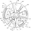
图1是根据实施例的微流体装置的俯视图;1 is a top view of a microfluidic device according to an embodiment;
图2是根据实施例的双层式微流体装置的结构视图;2 is a structural view of a double-layer microfluidic device according to an embodiment;
图3是根据实施例的三层式微流体装置的结构视图;3 is a structural view of a three-layer microfluidic device according to an embodiment;
图4是根据实施例的样品室和样品分配单元的详细视图;Figure 4 is a detailed view of a sample chamber and sample distribution unit according to an embodiment;
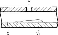
图5是示出根据实施例的常闭阀的截面图;5 is a cross-sectional view illustrating a normally closed valve according to an embodiment;
图6是用于解释打开图5的常闭阀的过程的截面图;6 is a sectional view for explaining the process of opening the normally closed valve of FIG. 5;
图7是示出根据实施例的反应剂盒的立体图;7 is a perspective view illustrating a reagent cartridge according to an embodiment;
图8是示出图1的微流体装置的立体图;8 is a perspective view showing the microfluidic device of FIG. 1;
图9示出了根据实施例的样品分析系统。Fig. 9 shows a sample analysis system according to an embodiment.
具体实施方式Detailed ways
现在,将详细描述实施例,其示例在附图中示出,其中,相同的标号始终指示相同的元件。注意的是,本实施例可具有不同的形式且不应该被解释为限于在此阐述的描述。因此,下面仅通过参照附图描述实施例,以解释本描述的各方面。Embodiments will now be described in detail, examples of which are illustrated in the accompanying drawings, wherein like reference numerals refer to like elements throughout. Note that the present embodiments may have different forms and should not be construed as being limited to the descriptions set forth herein. Accordingly, the embodiments are merely described below, by referring to the figures, to explain aspects of the present description.
图1示出了根据实施例的微流体装置。参照图1,根据本实施例的微流体装置包括可旋转的平台100(例如,盘形平台)以及微流体结构,所述微流体结构提供容纳流体的空间以及通道,流体可通过所述通道在平台100中流动。平台100可绕中心C旋转。即,微流体装置可安装在分析器的旋转驱动单元(图9中的510)上并被旋转。在这种情况下,在布置在平台100中的微流体结构中,可根据因平台100的旋转而产生的离心操作使样品运动、混合等。Fig. 1 shows a microfluidic device according to an embodiment. Referring to FIG. 1 , the microfluidic device according to the present embodiment includes a rotatable platform 100 (for example, a disk-shaped platform) and a microfluidic structure, and the microfluidic structure provides a space for containing a fluid and a channel through which the fluid can pass through the channel.
平台100可由诸如丙烯酸树脂、聚二甲基硅氧烷(PDMS)等的塑性材料形成,所述塑性材料可容易地成型且具有生物学上的惰性表面。然而,用于形成平台100的材料不限于此,且用于形成平台100的材料可以是具有化学和生物学稳定性、透光性、机械可加工性的任何材料。平台100可由多个层形成,当将所述多个层层叠或结合在一起时所述多个层可形成微流体结构。具有深度的压下或凹陷的结构(例如,室或通道)形成在所述多个层中的至少一个层的一个表面,且可通过将所述多个层结合而使空间和通道设置在平台100内部。例如,如图2所示,平台100可以是包括下层和上层的双层式结构。此外,如图3所示,平台100可以是包括分隔板的结构,所述分隔板用于限定用于容纳流体的空间和流体可流过的流动通道。平台100还可以以各种其他方式形成。
当平台100由多个层形成时,可使用粘合剂将所述多个层结合。例如,当平台100是包括下层和上层的双层结构时,可使用设置在下层和上层之间的粘合剂将下层和上层结合。粘合剂可以是施加在下层和/或上层上的液体材料。粘合剂可以是被UV(紫外线)射线照射而固化的UV固化粘合剂。粘合剂还可以是被可见光射线照射而固化的可见光固化粘合剂。When
粘合剂可包括固化树脂和光聚合引发剂。固化树脂可包括丙烯酸材料(例如,环氧丙烯酸酯、氨酯丙烯酸酯、聚酯丙烯酸酯或者硅酮丙烯酸酯)。固化树脂可包括诸如异氰脲酸三芳基酯或马来酸二芳基酯的多烯材料或者诸如三硫代丙酸三羟甲基丙烷酯的多硫羟酸材料。固化树脂可包括环氧树脂或乙烯基醚。固化树脂还可包括以上材料的组合。The adhesive may include a curable resin and a photopolymerization initiator. The curing resin may include an acrylic material (eg, epoxy acrylate, urethane acrylate, polyester acrylate, or silicone acrylate). The curing resin may include a polyene material such as triaryl isocyanurate or diaryl maleate or a polythiol acid material such as trimethylolpropane trithiopropionate. Curing resins may include epoxy resins or vinyl ethers. The cured resin may also include combinations of the above materials.
UV固化粘合剂中的光聚合引发剂可包括苯偶姻醚、苯甲酮材料、氨化材料、苯乙酮材料、噻吨酮材料、路易斯酸材料(例如,路易斯酸重氮盐、路易斯酸锍或者路易斯酸碘鎓)、或者这些的组合。Photopolymerization initiators in UV-curable adhesives can include benzoin ethers, benzophenone materials, ammoniated materials, acetophenone materials, thioxanthone materials, Lewis acid materials (e.g., Lewis acid diazonium salts, Lewis sulfonium acid or iodonium lewisate), or a combination of these.
可见光固化粘合剂中的光聚合引发剂可包括α-二酮材料(例如,樟脑奎宁、α-萘基或苯甲基、2,4-二乙基噻吨酮、三甲基苯甲酰基二苯基氢氧化硫、甲基噻吨酮、或者这些的组合)。Photopolymerization initiators in visible light-curable adhesives may include α-diketone materials (e.g., camphorquinine, α-naphthyl or benzyl, 2,4-diethylthioxanthone, trimethylbenzyl acyldiphenylsulfhydroxide, methylthioxanthone, or a combination of these).
光聚合引发剂的吸收光谱可在大约200nm至大约900nm的波长内具有最大值。此外,光聚合引发剂的吸收光谱还可在大约250nm至大约600nm的波长内具有最大值。The absorption spectrum of the photopolymerization initiator may have a maximum value within a wavelength of about 200 nm to about 900 nm. In addition, the absorption spectrum of the photopolymerization initiator may also have a maximum value within a wavelength of about 250 nm to about 600 nm.
除了固化树脂和光聚合引发剂之外,粘合剂还可包括光敏剂。光敏剂可消耗氧并给光聚合引发剂提供氢,从而促进固化反应。例如,光敏剂可包括甲基丙烯酸二甲胺乙酯、正丁胺、三乙胺、4-二甲胺基苯甲酸、异戊基、氢硅烷材料、磺酰肼衍生物、或者这些的组合。粘合剂还可包括其他稳定剂、填充剂、染料、颜料等。The adhesive may include a photosensitizer in addition to the curing resin and the photopolymerization initiator. The photosensitizer can consume oxygen and donate hydrogen to the photopolymerization initiator, thereby promoting the curing reaction. For example, photosensitizers may include dimethylaminoethyl methacrylate, n-butylamine, triethylamine, 4-dimethylaminobenzoic acid, isoamyl, hydrosilane materials, sulfonyl hydrazide derivatives, or combinations of these . The binder may also include other stabilizers, fillers, dyes, pigments, and the like.
将描述使用粘合剂将下层和上层结合来制造平台100的示例性方法。粘合剂可施加在下层和/或上层上。可根据粘合剂的粘度使用各种方法施加粘合剂。可使用喷墨式方法施加低粘度的粘合剂,在喷墨式方法中使用具有至少一个喷嘴的喷墨式打印机,粘合剂通过所述至少一个喷嘴被喷射。通过喷墨式打印机的喷嘴一次喷射的粘合剂的量可在大约1pl(皮升)至100μl(微升)之间的范围内。然而,粘合剂的施加方法不限于喷墨式方法,且可使用其他不同的方法。即,可通过使用丝网(silk-screen)的方法来施加高粘度的粘合剂。An exemplary method of fabricating the
接下来,可使下层和上层彼此附着,因此粘合剂可设置在下层和上层之间。可将电磁波照射到粘合剂。为了将具有期望波长的光照射到粘合剂,可使用滤光器。粘合剂中的光聚合引发剂可吸收光并产生自由基(radical)。光聚合引发剂的自由基可使固化树脂附近的区域变成自由基。可通过聚合作用使固化树脂的自由基彼此结合,从而将下层和上层结合。Next, the lower and upper layers can be attached to each other, so an adhesive can be placed between the lower and upper layers. Electromagnetic waves may be irradiated to the adhesive. In order to irradiate light having a desired wavelength to the adhesive, an optical filter may be used. The photopolymerization initiator in the adhesive can absorb light and generate radicals. The radicals of the photopolymerization initiator can make the region near the cured resin into radicals. The radicals of the cured resin may be combined with each other through polymerization, thereby combining the lower layer and the upper layer.
平台100的多个层的结合不限于利用电磁波使粘合剂固化的示例。可根据粘合剂通过施加适当的热、压力、和/或电磁波使下层和上层彼此结合。The bonding of multiple layers of the
这里,将通过参照图1和其他相关附图描述布置在平台100中的示例性微流体结构。样品室10被设置为更靠近平台100的中心C。样品容纳在样品室10中。用于载入样品的开口11可形成在样品室10中。Here, an exemplary microfluidic structure disposed in the
可在平台100中设置至少两个样品室以及至少两个分析单元,所述分析单元容纳来自样品室的样品并分析所述样品。在本实施例中,平台包括容纳来自共同的样品室(样品室10)的样品的第一分析单元101和第二分析单元102。At least two sample chambers and at least two analysis units accommodating samples from the sample chambers and analyzing the samples may be provided in the
例如,第一分析单元101和第二分析单元102可测试要求不同稀释比的项目。例如,通常使血清与稀释液按大约1:100的稀释比来稀释用于血液的测试项目(例如,白蛋白(ALB)、淀粉酶(AMY)、血液尿素氮(BUN)、钙(Ca++)、总胆固醇(CHOL)、氯化物(Cl-)、肌氨酸(CRE)、葡萄糖(GLU)、γ谷氨转移酶(GGT)、高浓度脂蛋白胆固醇(HDL)、钾(K+)、乳酸脱氢酶(LD)、钠(Na+)、总蛋白(TP)、甘油三酯(TRIG)、尿酸(UA))。通常使血清与稀释液按大约1:20的稀释比来稀释丙氨酸转氨酶(ALT)、丙氨酸磷酸酶(ALP)、天冬氨酸转氨酶(AST)、肌酸激酶(CK)、直接胆红素(D-BIL)、总胆红素(T-BIL)。因此,第一分析单元101可测试血清与稀释液按大约1:100的稀释比来稀释的项目,第二分析单元102可测试血清与稀释液按大约1:20的稀释比来稀释的项目。For example, the
第一分析单元101和第二分析单元102还可用于测试具有相同稀释比的项目。此外,第一分析单元101可测试需要离心分离的项目,第二分析单元102可测试不需要离心分离的项目。第一分析单元101的结构和第二分析单元102的结构基本上相同,因此,在下文中将只详细描述第一分析单元101的结构。The
第一分析单元101的样品分配单元30容纳来自样品室10的样品,并且可具有用于计量测试所需要的一定量的样品的预定容积。由于通过平台100的旋转产生的离心力被用于将样品从样品室10传输到样品分配单元30,所以样品分配单元30被设置为比样品室10更远离平台的中心C。样品分配单元30可用作利用平台100的旋转将样品(例如,血液)分离成上清液和沉淀物(固体物质)的离心分离器。用于离心分离的样品分配单元30可以以各种方式形成,且样品分配单元30的示例在图1和图4中示出。参照图1和图4,样品分配单元30可包括:通道形上清液收集单元31,沿径向朝平台100的外周延伸;沉淀物收集单元32,设置在上清液收集单元31的端部,且能够收集具有大比重的沉淀物。The
第一分析单元101的样品分配单元30直接连接到样品室10,以容纳样品。通过样品传输单元20将第二分析单元102的样品分配单元30a连接到样品分配单元30。因此,样品从样品室10被供应到样品分配单元30以填充样品分配单元30,然后通过样品传输单元20填充样品分配单元30a。The
参照图4,样品传输单元20包括:第一连接部分21,连接到样品分配单元30;第二连接部分22,连接到样品分配单元30a。第一连接部分21和第二连接部分22可形成在样品传输单元20的外壁25上。沿径向从平台100的中心C到第二连接部分22的半径R2可大于从平台100的中心C到第一连接部分21的半径R1。对于在第一连接部分21和第二连接部分22之间的点,外壁25的曲率半径R可以是R1或更大,且外壁25的曲率半径R可从第一连接部分21朝第二连接部分22而逐渐增加。因此,通过由微流体装置的旋转产生的离心力将样品传输到样品分配单元30以填充样品分配单元30,然后将样品传输到样品传输单元20。然后,样品在样品传输单元20中流动,最初通过离心力使样品沿样品传输单元20的外壁25的内表面流动,然后通过第二连接部分22运动到样品分配单元30。当形成多个样品分配单元来容纳来自一个样品室的样品时,可避免不得不将样品载入到所述多个样品分配单元中的每个样品分配单元的不便。关于样品传输单元20的描述而使用的术语“外壁25”是指在构成样品传输单元20的外壁当中比其他壁更径向靠外的壁。Referring to FIG. 4 , the
样品分配通道34设置在上清液收集单元31的侧部,在血液用作样品的情况下,样品分配通道34将收集的上清液(例如,血清)分配给用于实施接下来的操作的结构。通过阀35将样品分配通道34连接到上清液收集单元31。The sample distribution channel 34 is provided on the side of the supernatant
阀35可以是可具有各种形状的微流体阀。阀35可以是毛细管阀,当预定的压力被施加时所述毛细管阀被动地打开,或者阀35可以是通过操作信号从外部接收电动力或能量而主动地操作的阀。阀35是常闭阀,从而在吸收电磁波能量之前没有流体可流过通道34。The
图5和图6是示出根据实施例的常闭阀的截面图。参照图5,根据本实施例的常闭阀可包括在室温下呈固态的阀材料V1。阀材料V1设置在通道C中并阻挡通道C(如图5所示)。阀材料V1在高温下熔化并运动到通道C内的空间中,且在通道C仍然打开的同时再次凝固(如图6所示)。从外部能量源照射的能量可以是电磁波能量,外部能量源可以是照射激光束的激光光源、照射可见光或红外射线的氙气灯或者发光二极管。当使用激光光源时,可包括至少一个激光二极管。可根据电磁波的波长选择外部能量源,所述电磁波可被包括在阀材料V1中的发热颗粒吸收。阀材料V1可以是热塑性树脂(例如,环烯烃共聚物(COC)、聚甲基丙烯酸甲酯(PMMA)、聚碳酸酯(PC)、聚苯乙烯(PS)、聚甲醛(POM)、全氟烷(PFA)、聚氯乙烯(PVC)、聚丙烯(PP)、聚对苯二甲酸乙二醇酯(PET)、聚醚醚酮(PEEK)、聚酰胺(PA)、聚砜(PSU)、或者聚偏氟乙烯(PVDF))。此外,阀材料V1可以是在室温下呈固态的相变材料。就这点而言,相变材料可以是蜡。当蜡被加热时,蜡被熔化、液化并膨胀。蜡的示例可包括石蜡、微晶蜡、合成蜡、天然蜡等。相变材料可以是凝胶或者热塑性树脂。凝胶的示例可包括聚丙烯酰胺、聚丙烯酸酯、聚甲基丙烯酸酯、聚乙烯胺等。可将吸收电磁波能量并产生热量的多个细小发热颗粒分散在阀材料V1中。细小发热颗粒可具有大约1nm至大约100μm的直径,以容易地通过具有大约0.1mm深度和大约1mm宽度的微小通道C。例如,当将电磁波能量(例如,通过激光灯)照射到细小发热颗粒时,细小发热颗粒的温度快速地增加,因此细小发热颗粒产生热量且均匀地分散在蜡中。细小发热颗粒可具有包括金属成分和疏水表面结构的芯以具有这些特性。例如,细小发热颗粒可包括Fe芯和周围的层。所述周围的层可由表面活性剂组成。表面活性剂分子可结合到Fe芯。细小发热颗粒可分散在载体油中。载体油也可以是疏水性的,以使具有疏水表面结构的细小发热颗粒可被均匀地分散。熔化的相变材料可与分散有细小发热颗粒的载体油混合,然后混合材料被载入到通道C中并凝固,从而阻挡通道C。细小发热颗粒不限于上述的聚合物颗粒,但可以是量子点或磁珠。此外,细小发热颗粒可以是金属氧化物(例如,Al2O3、TiO2、Ta2O3、Fe3O4、或者HfO2)。同时,阀可仅由相变材料形成,而没有细小发热颗粒。5 and 6 are cross-sectional views illustrating a normally closed valve according to an embodiment. Referring to FIG. 5 , the normally closed valve according to the present embodiment may include a valve material V1 that is solid at room temperature. Valve material V1 is disposed in channel C and blocks channel C (as shown in FIG. 5 ). Valve material V1 melts at high temperature and moves into the space within channel C, and solidifies again while channel C remains open (as shown in FIG. 6 ). The energy irradiated from an external energy source may be electromagnetic wave energy, and the external energy source may be a laser light source for irradiating a laser beam, a xenon lamp for irradiating visible light or infrared rays, or a light emitting diode. When a laser light source is used, at least one laser diode may be included. The external energy source may be selected according to the wavelength of electromagnetic waves that may be absorbed by the heat-generating particles included in the valve material V1. The valve material V1 can be a thermoplastic resin (e.g., cycloolefin copolymer (COC), polymethylmethacrylate (PMMA), polycarbonate (PC), polystyrene (PS), polyoxymethylene (POM), perfluorinated Alkanes (PFA), polyvinyl chloride (PVC), polypropylene (PP), polyethylene terephthalate (PET), polyether ether ketone (PEEK), polyamide (PA), polysulfone (PSU) , or polyvinylidene fluoride (PVDF)). In addition, the valve material V1 may be a phase change material that is solid at room temperature. In this regard, the phase change material may be wax. When the wax is heated, the wax is melted, liquefied and expanded. Examples of waxes may include paraffin waxes, microcrystalline waxes, synthetic waxes, natural waxes, and the like. The phase change material can be a gel or a thermoplastic resin. Examples of gels may include polyacrylamide, polyacrylate, polymethacrylate, polyvinylamine, and the like. A plurality of fine heat-generating particles that absorb electromagnetic wave energy and generate heat can be dispersed in the valve material V1. The fine heat generating particles may have a diameter of about 1 nm to about 100 μm to easily pass through the minute channel C having a depth of about 0.1 mm and a width of about 1 mm. For example, when electromagnetic wave energy (for example, by laser light) is irradiated to the fine heat-generating particles, the temperature of the fine heat-generating particles rapidly increases so that the fine heat-generating particles generate heat and are uniformly dispersed in the wax. The fine heat-generating particles may have a core including a metal component and a hydrophobic surface structure to have these characteristics. For example, fine heat-generating particles may include Fe cores and surrounding layers. The surrounding layer may consist of surfactants. Surfactant molecules can bind to the Fe core. Fine heat-generating particles can be dispersed in carrier oil. The carrier oil may also be hydrophobic, so that fine heat-generating particles with a hydrophobic surface structure can be uniformly dispersed. The molten phase change material may be mixed with carrier oil dispersed with fine heat-generating particles, and then the mixed material is loaded into the channel C and solidified, thereby blocking the channel C. The fine heat-generating particles are not limited to the above-mentioned polymer particles, but may be quantum dots or magnetic beads. In addition, the fine heat-generating particles may be metal oxides (for example, Al2 O3 , TiO2 , Ta2 O3 , Fe3 O4 , or HfO2 ). Meanwhile, the valve can be formed only of the phase change material without fine heat generating particles.
样品分配通道34连接到上清液计量室50,上清液计量室50容纳从样品分离的上清液。通过阀51将上清液计量室50连接到稀释液室60。阀51可以是具有与上述阀35相同形状的微流体阀。The sample distribution channel 34 is connected to a
稀释液室60容纳样品稀释液,样品稀释液是上清液和稀释液按期望比例的混合物。因此,在应用中使用的术语“样品稀释液”意思是利用稀释液调节到期望浓度的样品。可预先确定期望的样品浓度,且生物样品分析领域的技术人员可容易地确定期望的样品浓度。考虑到上清液和稀释液的稀释比,预定量的稀释缓冲液容纳在稀释液室60中,稀释缓冲液通常用于样品的分析。考虑到稀释比,上清液计量室50被设计为具有能够容纳预定量的样品的容积。只要阀51保持在关闭状态,则任何样品都不会从上清液计量室50引入到稀释液室60中(即使上清液计量室被充满)。因此,任何期望的量的样品可被供应到稀释液室60。The
多个反应室70被设置为其与平台的中心C的距离比稀释液室60与平台的中心C的距离远。通过分配通道61将反应室70连接到稀释液室60。样品稀释液通过分配通道61的分配可受阀62控制。阀63提供通风路径,以使样品稀释液可容易地分配在反应室70中。阀62和阀63可以是具有与上述阀35的形状相同形状的微流体阀。The plurality of
适合于与样品成分进行不同反应的试剂可容纳在反应室70中。可在微流体装置的制造期间在将用于形成平台100的上层和下层结合之前载入试剂。此外,反应室70可具有通风孔和开口,而不是封闭式反应室。在这样的反应室的情况下,可在进行测试之前将试剂载入到反应室70中。试剂可以是液体或者呈冻干的固态。Reagents suitable for various reactions with sample components may be accommodated in the
例如,可在微流体装置的制造期间在将形成平台100的上层和下层结合之前将液体试剂载入到反应室70中,并且可同时通过冻干程序将液体试剂冻干。因此,通过将上层和下层结合而提供容纳冻干的试剂的微流体装置。可选地,冻干的试剂可容纳在可去除的壳或盒中(所述可去除的壳或盒可被载入到反应室70中)。可通过将填充剂和表面活性剂添加到液体试剂并使混合物冻干来提供冻干的试剂。填充剂确保冻干的试剂具有多孔渗水结构,以当样品稀释液被载入到反应室70中时可使冻干的试剂容易地溶解。例如,填充剂可以是牛血清白蛋白(BSA)、聚乙二醇(PEG)、葡聚糖、甘露醇、多元醇、肌醇、柠檬酸、乙二胺四乙酸二钠盐(EDTA2Na)、或者聚氧乙烯月桂醚(BRIJ-35)。可使用至少一种或两种填充剂。填充剂的类型可取决于试剂的类型。例如,表面活性剂可以是聚乙二醇、月桂醚、辛苯昔醇、聚乙烯烷基醇、壬基酚聚氧乙烯醚;环氧乙烷、乙氧化十三烷醇、聚氧乙烯壬基苯基醚磷酸钠盐以及十二烷基硫酸钠中的一种。可添加至少一种或两种表面活性剂。表面活性剂的类型可取决于试剂的类型。For example, liquid reagents may be loaded into the
此外,容纳呈冻干状态的试剂的试剂盒105(如图7所示)可设置在各个反应室70中(或者被插入到各个反应室70中)。在这种情况下,可通过将容纳液体试剂的试剂盒105经过冻干处理来提前制备容纳冻干的试剂的试剂盒105。In addition, a reagent cartridge 105 (as shown in FIG. 7 ) containing reagents in a lyophilized state may be provided in (or inserted into) each
参考单元103可设置在平台100中,参考单元103用于提供参考值且不容纳来自样品室10的样品。稀释液可储藏在稀释液室80中,以当检测反应时获得参考值。多个室90可被设置为其与平台100的中心C的距离比稀释液室80与平台100的中心C的距离远,多个室90为空或容纳稀释液以获得检测参考值。通过通道81将多个室90连接到稀释液室80。阀82可形成在通道81中。阀83用于提供通风路径。阀82和阀83可以与阀35相同。设置在通道81的端部的室91用于确定是否所有的室90都容纳有稀释液。A
虽然未详细描述,但是用于排放微流体装置内部的空气的多个通风路径可设置在微流体装置中。Although not described in detail, a plurality of ventilation paths for exhausting air inside the microfluidic device may be provided in the microfluidic device.
在下文中,将参照图1描述使用根据当前实施例的微流体装置获得可靠的分析结果的室(所述室可被总体称为质量控制(QC)室)。Hereinafter, a chamber for obtaining reliable analysis results using the microfluidic device according to the present embodiment (the chamber may be collectively referred to as a quality control (QC) chamber) will be described with reference to FIG. 1 .
使用前检测室41设置在样品分配单元30的端部,以检查微流体装置以前是否使用过。在将样品从样品室10供应到样品分配单元30之前,可通过使用检测器(图9中的520,稍后将描述)测量使用前检测室41的吸光率来检测样品是否存在于使用前检测室41中,从而确定微流体装置以前是否使用过。A
过量样品室42用于确定适合于测试的足够量的样品是否被供应到样品分配单元30。可通过通道将过量样品室连接到分析单元的样品分配单元的端部(通常是靠近旋转中心C的端部)。在图1中示出的示例性实施例中,通过通道42a将过量样品室42连接到第二分析单元102的样品分配单元30a的上端部。样品室10的样品填充样品分配单元30,然后流经样品传输单元20,以填充样品分配单元30a。然后,通过通道42a将剩余的样品传输到过量样品室42。在将样品从样品室10供应到样品分配单元30和30a之后,为了检查用于测试的期望量的样品是否被供应到样品分配单元30和30a,可在执行离心分离之前通过使用检测器(图9中的520,稍后将描述)测量过量样品室42的吸光率来确定样品是否存在于过量样品室42中。当包括至少两个分析单元用于容纳来自单个样品室10的样品时,过量样品室42连接到最后容纳样品的分析单元的样品分配单元。此外,当包括用于将样品供应到所述多个分析单元的多个样品室时,可设置连接到各个分析单元的样品分配单元的多个过量样品室。
上清液检测室43在样品分配单元30的上清液收集单元31和稀释液室60之间连接到样品分配通道34。在一个实施例中,通过通道36将上清液检测室43连接到样品分配通道34。在一个实施例中,上清液检测室43在样品分配单元30的上清液收集单元31和过量上清液室44之间连接到样品分配通道34。当阀35打开时,上清液填充上清液检测室43。使用检测器(图9中的520)测量上清液检测室43的吸光率。可通过测量上清液检测室43的吸光率来检查阀35的操作状态。例如,如果测量的吸光率指示上清液检测室43为空,则可意味着阀35没有适当地操作。The
上清液检测室43可用于检查上清液的功能状态。可基于上清液检测室43的测量的吸光率计算均裂指数、黄疸指数、脂血(lipemia)指数。The
过量上清液室44可在上清液收集单元31和稀释液室之间连接到样品分配通道34。可通过通道37将过量上清液室44连接到样品分配通道34。阀38可形成在通道37中。与阀35一样,阀38也是常闭阀。当阀38打开时,上清液填充上清液计量室50,并流入过量上清液室44中。可通过确定过量上清液室44的吸光率水平来检查上清液的量是否不足。The excess
上清液检测室43和过量上清液室44可用作第一浓度确定室,与第二浓度确定室45一起用于确定样品稀释液的稀释比是否合适。在这种情况下,上清液检测室43的深度和过量上清液室44的深度可以不同。根据比尔-朗伯定律(Beer–Lambert law),吸光率与样品的浓度和光路径的长度成比例。换句话说,当样品的浓度相同而光路径的长度不同时,吸光率与光路径的长度成比例地变化。此外,当光路径的长度相同而样品的浓度不同时,吸光率与样品的浓度成比例地变化。由于相同浓度的上清液容纳在上清液检测室43和过量上清液室44中,所以可通过测量上清液检测室43和过量上清液室44的吸光率来计算光路径的长度(即,两个室的深度)与吸光率之间的关系。The supernatant
第二浓度确定室45用于计算样品稀释液的吸光率。第二浓度确定室45设置在通过分配通道61连接到稀释液室60的多个室中的与稀释液室60第二最近的位置,且通过分配通道61容纳样品稀释液。至少一个流体室(dummychamber)45a可设置在第二浓度确定室45前面。The second
样品稀释液检测室46用于确定样品稀释液是否容纳在所有的反应室70中。在样品稀释液检测室46中没有容纳试剂。样品稀释液检测室46设置在分配通道61的端部(即,设置在所有其他反应室都容纳有样品稀释液之后最后分配样品稀释液的位置)。通过分配通道61供应的样品稀释液最后填充样品稀释液检测室46。因此,通过测量样品稀释液检测室46的吸光率,可确定是否所有的反应室70都容纳有样品稀释液。例如,如果样品稀释液检测室46的测量的吸光率水平指示样品稀释液检测室46为空,则可意味着阀62有操作缺陷。The sample
温度测量室47用于确定样品的温度是否适合于在样品上实施测试。为此,例如,可将其吸光率响应于其温度变化而变化的材料供应到温度测量室47。例如,丙烯酸树脂染料(thyon dye)可被供应到温度测量室47。通过使用检测器(图9中的520,稍后将描述)测量温度测量室47的吸光率,可确定微流体装置的温度适合于实施测试。温度测量室47可设置在微流体装置上的任何位置。The
变性检测室48用于确定微流体装置的储藏条件。为此,其吸光率根据其温度变化和/或含水量或水汽含量而变化的材料可容纳在变性检测室48中。在当前实施例中,参考单元103的多个室90中的一个室用作变性检测室48,但是本实施例不限于此,多个室90中的两个或者更多个室也可用作变性检测室。Denaturation detection chamber 48 is used to determine the storage condition of the microfluidic device. For this purpose, a material whose absorbance changes according to its temperature change and/or water content or water vapor content may be accommodated in the denaturation detection chamber 48 . In the current embodiment, one of the plurality of
第二浓度确定室45和样品稀释液检测室46可一起用作用于确定样品稀释液的稀释比是否恒定的室。The second
为了使检测器(图9的520)的运动最小,QC室41-48、反应室70、多个室90可设置在与平台100的中心C相同的径向距离处。To minimize detector (520 of FIG. 9 ) movement, QC chambers 41 - 48 ,
图8是根据实施例的微流体装置的立体图。参照图8,根据本实施例的微流体装置包括设置在平台100的侧部的条形码140。条形码140可附着到平台100的侧部。微流体装置的制造日期以及微流体装置的有效期可预先记录在条形码140中。此外,条形码140可包括与反应室70的吸光率水平和待检测/分析材料的浓度之间的关系相关的数据,从而允许测试结果的即时读取。此外,指示上清液检测室43的吸光率水平和上清液的状态之间的关系的数据(例如,均裂指数、黄疸指数、脂血指数)可预先记录在条形码140中。8 is a perspective view of a microfluidic device according to an embodiment. Referring to FIG. 8 , the microfluidic device according to the present embodiment includes a
图9示出了根据实施例的使用图1的微流体装置的样品分析系统。参照图9,根据实施例的使用微流体装置的样品分析系统包括旋转驱动单元510、检测器520以及电磁波发生器530。旋转驱动单元510使微流体装置旋转以提供用于样品的离心分离和流体运动的离心力。旋转驱动单元510使微流体装置在预定的位置停止,以使微流体装置的阀面对电磁波发生器530。电磁波发生器530照射用于打开阀的电磁波(例如,激光)。电磁波发生器530可沿微流体装置的径向移动。此外,旋转驱动单元510使微流体装置在预定的位置停止,以使室和检测器520对准。虽然未在图9中示出,但是旋转驱动单元510还可包括电机驱动单元,该电机驱动单元可控制微流体装置的角度位置。例如,电机驱动单元可使用步进电机或直流电机。检测器520检测待检测材料的光学特性(例如,荧光性质、发光性质、和/或吸光性质)。条形码读取器540检测形成在平台100的侧部的条形码。旋转驱动单元510、检测器520、电磁波发生器530、条形码读取器540设置在预定的测量室550中。加热器560将测量室550的温度保持在适合于测试的温度。控制样品分析过程的控制单元570设置在测量室550的外部。FIG. 9 illustrates a sample analysis system using the microfluidic device of FIG. 1 according to an embodiment. Referring to FIG. 9 , a sample analysis system using a microfluidic device according to an embodiment includes a
在下文中,将描述使用微流体装置分析样品的方法。在当前实施例中,作为示例将描述分析血液的方法。Hereinafter, a method of analyzing a sample using a microfluidic device will be described. In the present embodiment, a method of analyzing blood will be described as an example.
<供应样品><Supply samples>
微流体装置的稀释液室60和80可预先容纳稀释液。如果稀释液室60和80没有预先容纳稀释液,则可通过开口(未示出)将稀释液供应到稀释液室60和80。从病人身上获得的全血样品被供应到样品室10,微流体装置安装在旋转驱动单元510上。The
<获得条形码数据><Get barcode data>
使用条形码读取器540读取位于平台100的侧部的条形码140的数据。可从预先记录在条形码140中的数据检查微流体装置的制造日期和有效期,并且可通过检查有效期来确定微流体装置是否处于能够实施有效测试的状态。如果微流体装置未处于能够实施有效测试的状态,则控制单元570可产生需要替换微流体装置的警报。此外,预先记录在条形码140中的数据可包括与待分析材料的吸光率水平和浓度之间的关系有关的数据,从而允许操作者将所述关系应用到测量的吸光率水平。控制单元570可执行这样的比较,并且以期望的格式或指示符产生测试结果。The data of the
<确定微流体装置是否已使用过><Determination of whether the microfluidic device has been used>
使用检测器520测量设置在样品分配单元30的端部的使用前检测室41的吸光率。结果,如果测量的吸光率指示使用前检测室41包含血液或血液成分,则可意味着微流体装置已使用过。在这种情况下,控制单元570产生需要替换微流体装置的警报。The absorbance of the
<确定微流体装置的储藏条件><Determination of storage conditions for microfluidic devices>
使用检测器520测量变性检测室48的吸光率。由于材料(所述材料根据水汽含量和/或温度的变化而变性,且所述材料的吸光率相应地变化)容纳在变性检测室48中,所以可通过检测变性检测室48的吸光率来确定微流体装置的储藏状态。容纳在反应室70中的用于样品分析的试剂通常保持在大约4℃的温度,以保持试剂的活性。如果试剂没有以合适的条件储藏(即,如果试剂在不合适的条件下储藏一定的时间段),则容纳在反应室70中的试剂可丧失其活性。如果微流体装置的储藏条件差,则控制单元570可产生需要替换微流体装置的警报。The absorbance of denaturation detection chamber 48 is measured using
<测量温度><measurement temperature>
通过使用检测器520来测量温度测量室47的吸光率。由于其吸光率根据温度而变化的丙烯酸树脂染料(thyon dye)被供应到温度测量室47,所以可从温度测量室47的吸光率检测微流体装置的温度。微流体装置可保持低温,以保持稀释液和试剂的活性。由于在低温下保持了一定的时间段的微流体装置不能立即用于测试,所以当微流体装置的温度不在适合于开始测试的温度(例如,20℃)之上时,控制单元570产生指示低温和/或有必要使装置变暖的消息。在这种情况下,装置可被设定为等待(例如)1分钟。可通过驱动加热器560来升高测量室550的温度。然后,重复通过测量温度测量室47的吸光率来测量微流体装置的温度的操作,以使微流体装置达到适合于开始测试的温度,然后可实施测试。可预先适当地设定重复的次数,如果在开始测试之前仍未达到期望的温度,则控制单元570可产生错误或警告消息。The absorbance of the
<确定样品的量是否合适><Determination of whether the amount of the sample is appropriate>
通过使微流体装置以低速旋转而将血液样品从样品室10传输到样品分配单元30。就这点而言,低速是指产生合适的离心力以使流体运动的旋转速度。例如,微流体装置可以以1800rpm/10秒的加速度旋转11秒。可通过离心力使样品从样品室10运动到样品分配单元30。在填充样品分配单元30之后,通过样品传输单元20使样品运动到样品分配单元30a。在填充样品分配单元30a之后,通过通道42a使血液样品运动到过量样品室42。检测器520测量过量样品室42的吸光率。吸光率根据过量样品室42中的血液样品的量而变化。如果基于过量样品室42的测量的吸光率确定血液样品的量不足,则控制单元570可停止分析并产生警报,以将更多的血液样品供应到样品室10。The blood sample is transferred from the
<样品的离心分离><Centrifugal separation of samples>
如果基于过量样品室42的测量的吸光率确定血液样品的量足够,则离心分离血液。旋转驱动单元510使微流体装置高速旋转。就这点而言,高速是指可将血液分成上清液(例如,血清或血浆)和沉淀物(例如,血细胞)的旋转速度。例如,微流体装置可以以3600rpm/10秒的加速度旋转大约160秒。然后,重的血细胞被传输到沉淀物收集单元32,而上清液仍留在上清液收集单元31中。If the amount of blood sample is determined to be sufficient based on the measured absorbance of the
<计量上清液><Measurement supernatant>
使用电磁波发生器530将电磁波照射到常闭阀35。然后,如图6所示,阀材料V熔化,因此打开阀35。旋转驱动单元510使微流体装置旋转以产生离心力。然后,通过样品分配通道34将上清液从上清液收集单元31传输到上清液计量室50和上清液检测室43。由于位于上清液计量室50的出口的阀51是常闭阀,所以上清液填充上清液计量室50。Electromagnetic waves are irradiated to the normally closed
<确定阀35的故障><Determination of failure of
使用检测器520测量上清液检测室43的吸光率。当上清液检测室43的吸光率指示上清液检测室43为空时,可指示阀35没有适当地操作,且上清液没有运动到上清液计量室50和上清液检测室43。在这种情况下,使用电磁波发生器530再次执行打开阀35的操作,并且可再次测量上清液检测室43的吸光率。可适当地设定测量的次数。例如,一旦在重复操作多次后测量的吸光率仍指示上清液检测室43为空时,控制单元570可显示阀35的操作错误或警报,并产生需要替换微流体装置的警报。The absorbance of the
<确定上清液的状态><Determining the status of the supernatant>
当测量的吸光率指示上清液检测室43未充满或者未容纳足够量的上清液时,可使用上清液检测室43的测量的吸光率检查上清液的状态。例如,通过使用预先记录在条形码140中的数据,可计算装置中上清液的均裂指数、黄疸指数、脂血指数。这些指数可用于将可靠的结果与不可靠的结果分类。When the measured absorbance indicates that the
<确定上清液的量><Determining the amount of supernatant>
使用电磁波发生器530打开设置在通道37的入口的阀38。当微流体装置旋转时,通过离心力使上清液收集单元31和样品分配通道34中的上清液流入过量上清液室44中。使用检测器520测量过量上清液室44的吸光率。当测量的吸光率指示过量上清液室44包含足够的或适量的上清液(这可被预先确定)时,可意味着足够量的上清液容纳在上清液计量室50中。当测量的吸光率指示过量上清液室44未被充满且具有比预定水平大的空的空间时,可意味着上清液的量不足。在这种情况下,容纳在上清液计量室50中的上清液的量可能不足。此外,阀38可能未被适当地操作,因此可再次执行打开阀38的操作,并且可再次测量过量上清液室44的吸光率。测量操作只可重复一次。当吸光率的重复测量指示上清液的量仍然不足时,控制单元570可产生需要替换微流体装置的警报,且再次实施测试。The
<测量用于确定样品稀释液浓度的参考值><Measure the reference value for determining the concentration of the sample diluent>
当上清液检测室43的吸光率和过量上清液室44的吸光率处于期望的范围(“正常”)内时,吸光率可用于计算用于检测样品稀释液浓度的参考值。吸光率取决于室43或44中上清液的量以及上清液检测室43的深度(长度)和过量上清液室44的深度(长度)。假设上清液检测室43的深度和过量上清液室44的深度不同,则可计算上清液检测室43的深度和上清液检测室43的吸光率之间的关系以及过量上清液室44的深度和过量上清液室44的吸光率之间的关系。When the absorbance of the
<样品稀释液的形成><Formation of sample diluent>
使用电磁波发生器530打开阀51。当微流体装置旋转时,上清液从上清液计量室50运动到稀释液室60。还可打开阀63并形成通风路径。旋转驱动单元510可使微流体装置作数次往复运动,以使稀释液和上清液混合。因此,样品稀释液形成在稀释液室60中。The
<温度的再测量><Remeasurement of temperature>
可再次测量微流体装置的温度。例如,可在大约37℃±1℃的温度下实施对活体样品(例如,血液)的分析。用于血液分析的试剂通常被处理在上述温度下显示预定的吸光率。因此,检测器520检测温度测量室47的吸光率,以测量温度。当温度未达到大约37℃±1℃时,控制单元570产生用于变暖或加热的消息并待机等待。这里,通过驱动加热器560使测量室550的温度升高。然后,重复检测温度测量室47的吸光率,以测量微流体装置的温度。当微流体装置的温度达到大约37℃±1℃时,可继续实施测试。可适当地设定再测量温度的次数(例如,一次)。如果微流体装置的温度未达到大约37℃±1℃,则尽管重复测量,但是控制单元570仍可产生温度错误或警报消息,并结束或停止测试。此外,控制单元570可产生需要替换微流体装置的警报。The temperature of the microfluidic device can again be measured. For example, analysis of a living sample (eg, blood) can be performed at a temperature of about 37°C ± 1°C. Reagents for blood analysis are generally processed to exhibit a predetermined absorbance at the above-mentioned temperature. Therefore, the
<分配样品稀释液><Dispensing Sample Diluent>
使用电磁波发生器530打开阀62。当微流体装置旋转时,样品稀释液通过分配通道61填充过量上清液室44、反应室70以及样品稀释液检测室46。此外,使用电磁波发生器530打开阀82和阀83。当微流体装置旋转时,稀释液室80中的稀释液通过通道81填充室90。The
<确定样品稀释液的分配><Determining the distribution of the sample diluent>
使用检测器520测量设置在通道61的端部的样品稀释液检测室46的吸光率(来自分配通道61的样品稀释液最后分配在样品稀释液检测室46中)。当吸光率指示样品稀释液存在于样品稀释液检测室46中时,意味着样品稀释液已经完全填充反应室70。当测量的吸光率指示反应室70为空状态时,阀62可能未适当地操作。在这种情况下,再次执行打开阀62的操作,并且再次测量样品稀释液检测室46的吸光率。此外,当再次测量吸光率时,可再次执行打开阀51和阀62的操作。如果样品稀释液检测室46在第二次重复测量时或在第二次重复测量之后被确定为空,则控制单元570可产生需要替换微流体装置的警报。例如,可将再次再测量的次数设定为一次。The absorbance of the sample
使用检测器520测量参考单元103中的设置在通道81的端部的室91的吸光率(稀释液在所述端部被最后分配在室91中)。当吸光率指示室91包含稀释液时,可意味着稀释液已经填充室91。当测量的吸光率指示室91为空时,阀62可能没有适当地操作。在这种情况下,再次执行打开阀82的操作,并且再次测量室91的吸光率。如果室91仍被确定为空,则控制单元570可产生需要替换微流体装置的警报。例如,可将再测量的频率设定为一次。The absorbance of the
<检测阀51的故障><Failure of
使用检测器520测量设置在反应室70的端部的反应室71的吸光率(样品稀释液最后分配在反应室71中)。当测量的吸光率指示反应室71仅容纳稀释液时,意味着因阀51的故障导致上清液未与稀释液混合。由于只有稀释液容纳在参考单元103的室91中,所以当反应室71的吸光率和室91的吸光率相同时,意味着也只有稀释液存在于反应室71中。在这种情况下,控制单元570可产生错误或警报消息,并结束或停止分析。The absorbance of the
<测量用于分析的吸光率><Measurement of absorbance for analysis>
旋转驱动单元510可使微流体装置作往复运动,以使样品稀释液与试剂混合。然后,测量反应室70的吸光率和第二浓度确定室45的吸光率,必要时测量参考单元103的室90的吸光率。可通过测量吸光率(以一定的时间间隔重复测量吸光率),以检查所述各个室的吸光率直到反应结束,从而确定各个室中反应的终点。使用预先记录在条形码140中的吸光率和待检测成分的浓度之间的关系来计算关于多个分析项目中的每个分析项目的待检测成分的浓度。The
<确定稀释比><Determination of dilution ratio>
通过使用第二浓度确定室45的吸光率、上清液检测室43的吸光率、和/或过量上清液室44的吸光率来确定样品稀释液的稀释比是否合适。例如,当具有浓度C的样品被放入具有深度L1的室中时,样品的吸光率值为A1;当具有浓度C的同一样品被放入具有深度L2的室中时,样品的吸光率值A2为(L2/L1)A1。例如,当L1为6mm且L2为1.2mm时,A2为(1/5)A1。此外,当L1为6mm且L2为0.6mm时,A2为(1/10)A1。然后,通过使用具有浓度C的样品,样品稀释液被形成为样品与稀释液具有1:B的稀释比。然后,样品稀释液容纳在具有深度L3的室中,这里,样品稀释液的吸光率值被称为A3。样品稀释液中样品的浓度为C/B,由于吸光率值与光路径的长度成比例,所以A3为(1/B)(L3/L1)A1。例如,当L1=L3=6mm且B=100时,A3为(1/100)A1。此外,当L1=6mm、L3=1.2mm且B=100时,A3为(1/100)(1/5)A1=(1/500)A1。此外,当L1=L3=6mm且B=20时,A3为(1/20)A1。此外,当L1=6mm、L3=1.2mm且B=20时,A3为(1/20)(1/5)A1=(1/100)A1。因此,当第二浓度确定室45的吸光率、上清液检测室43的吸光率、和/或过量上清液室44的吸光率已知时,即使当上清液本身的浓度未知时,也可计算样品稀释液的吸光率值。Whether or not the dilution ratio of the sample diluent is appropriate is determined by using the absorbance of the second
当在微流体装置的制造期间上清液检测室43的深度(或长度)、过量上清液室44的深度(或长度)、第二浓度确定室45的深度(或长度)被确定并因此为已知时,可通过测量上清液检测室43和过量上清液室44中上清液的吸光率值来计算具有已知稀释比的样品稀释液的吸光率值。因此,当第二浓度确定室45中测量的吸光率值与吸光率值可允许的误差范围相同或者在吸光率值可允许的误差范围内(所述吸光率值的误差范围从上清液检测室43和过量上清液室44中测量的吸光率值估计而来)时,样品稀释液的稀释比可被确定为是合适的,且测试的结果也是可靠的。此外,可从第二浓度确定室45中测量的吸光率值以及在上清液检测室43和过量上清液室44中测量的吸光率值来计算样品稀释液的稀释比,并且当样品稀释液计算的稀释比与期望的稀释比的可允许的误差范围相同或者在期望的稀释比的可允许的误差范围内时,测试结果可被认为是可靠的。根据上述方法,即使当样品(上清液)的浓度未知时,也可仅从吸光率值和光路径的长度来测量样品稀释液的稀释比,并且可确定测试的可靠性。此外,可通过从上清液检测室43的吸光率和过量上清液室44的吸光率计算上清液的浓度和深度之间的关系并且使用第二浓度确定室45的吸光率和深度来确定样品稀释液的稀释比。When the depth (or length) of the supernatant
<确定稀释均匀度><Determination of dilution uniformity>
将第二浓度确定室45的吸光率与样品稀释液检测室46的吸光率或者设置在反应室70的端部的反应室71的吸光率比较。如果第二浓度确定室45的吸光率与样品稀释液检测室46的吸光率或者反应室71的吸光率相同,则可意味着容纳在所有反应室70中的样品稀释液的稀释比几乎相同,在这种情况下,分析的结果可被认为是准确的。当上清液和稀释液在稀释液室60中未均匀地混合时,第二浓度确定室45的吸光率与样品稀释液检测室46的吸光率或者反应室71的吸光率会彼此不同。The absorbance of the second
<检查反应室的气泡><Check for air bubbles in the reaction chamber>
当反应室70的吸光率以及参考单元103的多个室的吸光率指示其中存在过量气泡时,产生与有气泡产生的测试项目有关的错误消息。室或样品的吸光率的大幅波动可表明存在过量气泡。因此,可使用所述多个室的吸光率测量来确定是否存在过量气泡。When the absorbance of the
应该理解,在此描述的示例性实施例应该被认为仅仅是描述性说明而不是为了限制的目的。对各个实施例中的特征或方面的描述通常也被认为可用于其他实施例中的其他相似特征或方面。It should be understood that the exemplary embodiments described therein should be considered in a descriptive sense only and not for purposes of limitation. Descriptions of features or aspects within each embodiment should typically be considered as available for other similar features or aspects in other embodiments.
Claims (28)
Applications Claiming Priority (5)
| Application Number | Priority Date | Filing Date | Title |
|---|---|---|---|
| KR10-2008-0100763 | 2008-10-14 | ||
| KR20080100763 | 2008-10-14 | ||
| KR1020090063456AKR101099495B1 (en) | 2008-10-14 | 2009-07-13 | Centrifugal force-based microfluidic device, its manufacturing method and sample analysis method using the same |
| KR10-2009-0063456 | 2009-07-13 | ||
| PCT/KR2009/005893WO2010044598A2 (en) | 2008-10-14 | 2009-10-14 | Microfluidic device using centrifugal force and sample analyzing method using the microfluidic device |
Publications (2)
| Publication Number | Publication Date |
|---|---|
| CN102177439A CN102177439A (en) | 2011-09-07 |
| CN102177439Btrue CN102177439B (en) | 2013-12-25 |
Family
ID=42217352
Family Applications (1)
| Application Number | Title | Priority Date | Filing Date |
|---|---|---|---|
| CN2009801401798AActiveCN102177439B (en) | 2008-10-14 | 2009-10-14 | Microfluidic device using centrifugal force and sample analysis method using the same |
Country Status (8)
| Country | Link |
|---|---|
| US (1) | US8222045B2 (en) |
| EP (1) | EP2338061A4 (en) |
| JP (1) | JP2012506027A (en) |
| KR (1) | KR101099495B1 (en) |
| CN (1) | CN102177439B (en) |
| AR (1) | AR073847A1 (en) |
| TW (1) | TWI393874B (en) |
| WO (1) | WO2010044598A2 (en) |
Cited By (1)
| Publication number | Priority date | Publication date | Assignee | Title |
|---|---|---|---|---|
| TWI685651B (en) | 2017-12-12 | 2020-02-21 | 國立成功大學 | Micro fluid chip |
Families Citing this family (50)
| Publication number | Priority date | Publication date | Assignee | Title |
|---|---|---|---|---|
| US7925449B2 (en)* | 2006-09-18 | 2011-04-12 | Cfph, Llc | Products and processes for analyzing octane content |
| US20110014094A1 (en)* | 2009-07-20 | 2011-01-20 | Samsung Electronics Co., Ltd. | Disk type microfluidic device and blood testing apparatus using the same |
| KR20110031729A (en)* | 2009-09-21 | 2011-03-29 | 삼성전자주식회사 | Blood test disk, blood test apparatus having same and control method thereof |
| CA2795211C (en) | 2010-04-16 | 2018-11-06 | Opko Diagnostics, Llc | Feedback control in microfluidic systems |
| SI3270141T1 (en) | 2011-03-08 | 2021-03-31 | Universite Laval | Fluidic centripetal device |
| US9823221B2 (en)* | 2012-02-17 | 2017-11-21 | STRATEC CONSUMABLES GmbH | Microstructured polymer devices |
| KR101325725B1 (en)* | 2012-03-21 | 2013-11-08 | 국립대학법인 울산과학기술대학교 산학협력단 | Water analysing appratus and water analysing method using thereof |
| EP2856178B1 (en) | 2012-05-31 | 2020-07-15 | The University of North Carolina at Chapel Hill | Dissolution guided wetting of structured surfaces |
| US20140017806A1 (en)* | 2012-07-11 | 2014-01-16 | Samsung Electronics Co., Ltd. | Microfluidic structure, microfluidic device having the same and method of controlling the microfluidic device |
| KR20140009607A (en)* | 2012-07-11 | 2014-01-23 | 삼성전자주식회사 | Test device and control method thereof |
| CA2886470C (en) | 2012-10-08 | 2022-03-15 | General Electric Company | Sensitive and rapid method for detection of low levels of lal-reactive substances |
| KR101375752B1 (en) | 2013-01-16 | 2014-03-18 | 포항공과대학교 산학협력단 | Microfluidic unit, microfluidic disc, microfluidic disc system, and method for biochemical assays |
| CN105228749B (en)* | 2013-03-13 | 2018-03-27 | 塔霍农村卫生研究所有限公司 | Portable blood cell count monitor |
| KR102205650B1 (en)* | 2013-06-05 | 2021-01-21 | 넥서스 디엑스, 아이엔씨. | Microfluidic device, test apparatus, test system having the same and control method for the test apparatus |
| TWI499779B (en) | 2013-07-04 | 2015-09-11 | Ind Tech Res Inst | Detection chip and using method thereof |
| CN103513045B (en)* | 2013-08-23 | 2015-09-02 | 宁波美康保生生物医学工程有限公司 | Reagent detects integrated chip |
| WO2016002728A1 (en) | 2014-06-30 | 2016-01-07 | パナソニックヘルスケアホールディングス株式会社 | Substrate for sample analysis, sample analysis device, sample analysis system, and method for removing liquid from liquid that contains magnetic particles |
| JP6588908B2 (en) | 2014-06-30 | 2019-10-09 | Phcホールディングス株式会社 | Sample analysis substrate, sample analysis apparatus, sample analysis system, and program for sample analysis system |
| US10520521B2 (en) | 2014-06-30 | 2019-12-31 | Phc Holdings Corporation | Substrate for sample analysis, sample analysis device, sample analysis system, and program for sample analysis system |
| US10539560B2 (en) | 2014-06-30 | 2020-01-21 | Phc Holdings Corporation | Substrate for sample analysis, and sample analysis apparatus |
| WO2016024808A1 (en)* | 2014-08-12 | 2016-02-18 | Samsung Electronics Co., Ltd. | In-vitro diagnostic apparatus and in-vitro diagnostic method performed by in-vitro diagnostic apparatus |
| US10539583B2 (en) | 2014-12-12 | 2020-01-21 | Phc Holdings Corporation | Substrate for sample analysis, sample analysis device, sample analysis system, and program for sample analysis system |
| CN104502594B (en)* | 2014-12-22 | 2016-08-24 | 厦门大学 | A kind of blood hepatitis B, hepatitis C and syphilis examine centrifugal chip and detection method soon |
| KR20160081022A (en)* | 2014-12-30 | 2016-07-08 | 삼성전자주식회사 | Microfluidic device and method of detecting sample supplied to the same |
| TWI562829B (en)* | 2015-06-17 | 2016-12-21 | Delta Electronics Inc | Centrifugal channel device and centrifugal channel main body |
| USD841186S1 (en)* | 2015-12-23 | 2019-02-19 | Tunghai University | Biochip |
| WO2017111128A1 (en)* | 2015-12-24 | 2017-06-29 | パナソニックヘルスケアホールディングス株式会社 | Sample analysis substrate, sample analysis device, sample analysis system, and program for sample analysis |
| JP2017198623A (en)* | 2016-04-28 | 2017-11-02 | シャープライフサイエンス株式会社 | Measuring apparatus and measuring method |
| CN107561299B (en) | 2016-06-30 | 2021-08-31 | 希森美康株式会社 | Detection device and detection method |
| JP6457451B2 (en)* | 2016-06-30 | 2019-01-23 | シスメックス株式会社 | Detection apparatus and detection method |
| JP6740768B2 (en)* | 2016-07-20 | 2020-08-19 | 東ソー株式会社 | Lyophilized sample dilution reagent |
| CN106311107B (en)* | 2016-08-31 | 2018-10-23 | 东北大学 | A kind of method of centrifugal type microfludic chip and continuous synthesis Janus particles |
| WO2018134387A1 (en)* | 2017-01-20 | 2018-07-26 | Université Libre de Bruxelles | Immunoassay methods and devices |
| KR101965963B1 (en)* | 2017-08-24 | 2019-08-13 | 경희대학교 산학협력단 | Chip for Sample Analysis and Device for Sample Analysis containing the same, and Catridge Mounted on chip for Sample Analysis |
| JP6434114B1 (en)* | 2017-11-30 | 2018-12-05 | シスメックス株式会社 | Measuring method and measuring device |
| KR102056216B1 (en) | 2018-02-09 | 2019-12-16 | 광운대학교 산학협력단 | Sheet for Separating Sample Stacking Paper based using Centrifugal Force and Method using the same |
| WO2019187294A1 (en)* | 2018-03-30 | 2019-10-03 | 富士フイルム株式会社 | Tip, mixing device, and mixing method |
| KR102063865B1 (en)* | 2018-06-20 | 2020-01-08 | 울산과학기술원 | Centrifugal force based platelet isolation and testing system |
| KR102301178B1 (en)* | 2018-06-25 | 2021-09-09 | 주식회사 엘지화학 | A device for detecting Aldehyde/Ketone |
| KR101986464B1 (en)* | 2018-11-26 | 2019-06-05 | 경희대학교 산학협력단 | Chip for Sample Analysis and Device for Sample Analysis containing the same, and Catridge Mounted on chip for Sample Analysis |
| CN109884328A (en)* | 2019-03-01 | 2019-06-14 | 清华大学 | Lateral flow immunoassay system based on centrifugal microfluidic system |
| EP3972729A4 (en) | 2019-05-22 | 2022-12-21 | Citrogene Inc. | DEVICE AND METHOD FOR RAPID IDENTIFICATION OF MICROORGANISMS |
| CN110568202B (en)* | 2019-09-12 | 2022-05-24 | 重庆科技学院 | A microfluidic chip for automatic quantitative immunofluorescence quantitative rapid detection |
| CN110992784B (en)* | 2019-11-20 | 2021-11-09 | 万有造诣(深圳)教育科技有限公司 | Scientific test device for education and science and technology |
| CN111693432A (en)* | 2020-06-04 | 2020-09-22 | 山东大学 | Automatic monitoring system and method for water leakage on surface of structure |
| JP2023541822A (en)* | 2020-09-17 | 2023-10-04 | シトロジーン インコーポレイテッド | Microfluidic devices and methods for rapid high-throughput identification of microorganisms |
| CN114849797A (en)* | 2021-01-20 | 2022-08-05 | 南京岚煜生物科技有限公司 | Micro-fluidic chip based on phase-change material seals reagent |
| KR20230119302A (en) | 2022-02-07 | 2023-08-16 | 한라분석연구원 주식회사 | Multi-componet simultaneous analysis method utilizing GC-MS/MS and LC-MS/MS |
| KR20230119301A (en) | 2022-02-07 | 2023-08-16 | 한라분석연구원 주식회사 | Multi-componet simultaneous analysis method utilizing GC and LC |
| US12337335B2 (en)* | 2022-02-24 | 2025-06-24 | Hanguang Micro-Nano Technology (Taicang) Co., Ltd. | Biochemical item detection disc |
Citations (3)
| Publication number | Priority date | Publication date | Assignee | Title |
|---|---|---|---|---|
| US6527432B2 (en)* | 2000-05-15 | 2003-03-04 | Tecan Trading Ag | Bidirectional flow centrifugal microfluidic devices |
| US20080108120A1 (en)* | 2006-09-05 | 2008-05-08 | Samsung Electronics Co., Ltd. | Centrifugal force-based microfluidic device for nucleic acid extraction and microfluidic system including the microfluidic device |
| CN101194155A (en)* | 2005-04-09 | 2008-06-04 | 贝林格尔英格海姆米克罗帕茨有限责任公司 | Device and method for analyzing a sample liquid |
Family Cites Families (18)
| Publication number | Priority date | Publication date | Assignee | Title |
|---|---|---|---|---|
| EP0764266A4 (en)* | 1994-06-06 | 1998-08-05 | Abay Sa | Modified siphons for improved metering precision |
| AU4424299A (en)* | 1999-02-01 | 2000-08-18 | 3M Innovative Properties Company | Poly(alpha-olefin) adhesive cover tapes for analytical receptacles |
| AU5494900A (en)* | 1999-06-18 | 2001-01-09 | Gamera Bioscience Corporation | Devices and methods for the performance of miniaturized homogeneous assays |
| TW517154B (en)* | 1999-08-11 | 2003-01-11 | Asahi Chemical Ind | Analyzing cartridge and liquid feed control device |
| KR100739515B1 (en)* | 2000-06-20 | 2007-07-13 | 자이단호진 가와무라 리카가쿠 겐큐쇼 | Microdevice with laminated structure and manufacturing method thereof |
| JP2002122488A (en)* | 2000-10-17 | 2002-04-26 | Kawamura Inst Of Chem Res | Micro chemical device with temperature display mechanism |
| SE0201738D0 (en)* | 2002-06-07 | 2002-06-07 | Aamic Ab | Micro-fluid structures |
| WO2004058406A2 (en)* | 2002-12-24 | 2004-07-15 | Tecan Trading Ag | Microfluidics devices and methods for diluting samples and reagents |
| US7347617B2 (en)* | 2003-08-19 | 2008-03-25 | Siemens Healthcare Diagnostics Inc. | Mixing in microfluidic devices |
| RU2006110931A (en) | 2003-09-05 | 2007-10-20 | Кайлипер Лайф Сайенсиз, Инк. (Us) | ANALYZED SUBSTANCE INJECTION SYSTEM |
| JP2006003196A (en)* | 2004-06-17 | 2006-01-05 | Canon Inc | Evaluation method and apparatus for chemical state change of resin |
| KR100579831B1 (en)* | 2004-09-07 | 2006-05-15 | 삼성전자주식회사 | Assemble Microfluidic Biosample Processing System |
| WO2007052648A1 (en)* | 2005-11-02 | 2007-05-10 | Matsushita Electric Industrial Co., Ltd. | Disc for analyzing sample |
| KR100763907B1 (en) | 2005-12-26 | 2007-10-05 | 삼성전자주식회사 | Manufacturing method of microfluidic device and microfluidic device manufactured thereby |
| JP2007225555A (en)* | 2006-02-27 | 2007-09-06 | Konica Minolta Medical & Graphic Inc | Microchip, examination device using microchip, and examination system using microchip |
| JP4721958B2 (en)* | 2006-06-09 | 2011-07-13 | 株式会社日立ソリューションズ | Bead chip plate |
| JP2008128706A (en)* | 2006-11-17 | 2008-06-05 | Konica Minolta Medical & Graphic Inc | Microchip inspection system and program used for the microchip inspection system |
| JP2008164434A (en)* | 2006-12-28 | 2008-07-17 | Matsushita Electric Ind Co Ltd | Biological sample discrimination device |
- 2009
- 2009-07-13KRKR1020090063456Apatent/KR101099495B1/enactiveActive
- 2009-09-30USUS12/570,414patent/US8222045B2/enactiveActive
- 2009-10-13TWTW098134633Apatent/TWI393874B/enactive
- 2009-10-13ARARP090103932Apatent/AR073847A1/enactiveIP Right Grant
- 2009-10-14EPEP09820748.3Apatent/EP2338061A4/ennot_activeWithdrawn
- 2009-10-14WOPCT/KR2009/005893patent/WO2010044598A2/ennot_activeCeased
- 2009-10-14JPJP2011530962Apatent/JP2012506027A/ennot_activeCeased
- 2009-10-14CNCN2009801401798Apatent/CN102177439B/enactiveActive
Patent Citations (3)
| Publication number | Priority date | Publication date | Assignee | Title |
|---|---|---|---|---|
| US6527432B2 (en)* | 2000-05-15 | 2003-03-04 | Tecan Trading Ag | Bidirectional flow centrifugal microfluidic devices |
| CN101194155A (en)* | 2005-04-09 | 2008-06-04 | 贝林格尔英格海姆米克罗帕茨有限责任公司 | Device and method for analyzing a sample liquid |
| US20080108120A1 (en)* | 2006-09-05 | 2008-05-08 | Samsung Electronics Co., Ltd. | Centrifugal force-based microfluidic device for nucleic acid extraction and microfluidic system including the microfluidic device |
Cited By (1)
| Publication number | Priority date | Publication date | Assignee | Title |
|---|---|---|---|---|
| TWI685651B (en) | 2017-12-12 | 2020-02-21 | 國立成功大學 | Micro fluid chip |
Also Published As
| Publication number | Publication date |
|---|---|
| JP2012506027A (en) | 2012-03-08 |
| KR20100041664A (en) | 2010-04-22 |
| EP2338061A4 (en) | 2013-12-25 |
| TWI393874B (en) | 2013-04-21 |
| US20100093105A1 (en) | 2010-04-15 |
| WO2010044598A3 (en) | 2010-07-22 |
| CN102177439A (en) | 2011-09-07 |
| US8222045B2 (en) | 2012-07-17 |
| AR073847A1 (en) | 2010-12-09 |
| KR101099495B1 (en) | 2011-12-28 |
| WO2010044598A2 (en) | 2010-04-22 |
| TW201015059A (en) | 2010-04-16 |
| EP2338061A2 (en) | 2011-06-29 |
Similar Documents
| Publication | Publication Date | Title |
|---|---|---|
| CN102177439B (en) | Microfluidic device using centrifugal force and sample analysis method using the same | |
| US8539823B2 (en) | Microfluidic device and method of loading sample into the microfluidic device | |
| US9616424B2 (en) | Centrifugal-based microfluidic apparatus, method of fabricating the same, and method of testing samples using the microfluidic apparatus | |
| KR100997144B1 (en) | Microfluidic Device | |
| US8491840B2 (en) | Microfluidic device, sample analyzing method using the same, and dilution ratio measuring method | |
| US9289765B2 (en) | Micro-fluidic device and sample testing apparatus using the same | |
| JP5492886B2 (en) | Reagent cartridge, microfluidic device including the cartridge, manufacturing method of the microfluidic device, and biochemical sample analysis method using the microfluidic device | |
| KR101257700B1 (en) | Microfluidic device and microfluidic system including thereof | |
| KR101306338B1 (en) | Microfluidic device and microfluidic system including thereof | |
| KR101635075B1 (en) | Method and apparatus for measuring light absorbance | |
| US20090286327A1 (en) | Microfluidic device containing lyophilized reagent therein and analyzing method using the same | |
| KR20120091631A (en) | Microfluidic device | |
| EP3040126A1 (en) | Microfluidic device and method of detecting sample supplied to the same |
Legal Events
| Date | Code | Title | Description |
|---|---|---|---|
| C06 | Publication | ||
| PB01 | Publication | ||
| C10 | Entry into substantive examination | ||
| SE01 | Entry into force of request for substantive examination | ||
| C14 | Grant of patent or utility model | ||
| GR01 | Patent grant | ||
| TR01 | Transfer of patent right | Effective date of registration:20220901 Address after:Daejeon Patentee after:Prischen biosensor Co.,Ltd. Address before:Gyeonggi Do, South Korea Patentee before:SAMSUNG ELECTRONICS Co.,Ltd. | |
| TR01 | Transfer of patent right |