CN102176938A - Universal syringe with retractable needle - Google Patents
Universal syringe with retractable needleDownload PDFInfo
- Publication number
- CN102176938A CN102176938ACN200980140259.3ACN200980140259ACN102176938ACN 102176938 ACN102176938 ACN 102176938ACN 200980140259 ACN200980140259 ACN 200980140259ACN 102176938 ACN102176938 ACN 102176938A
- Authority
- CN
- China
- Prior art keywords
- needle
- syringe
- connector
- assembly
- retraction
- Prior art date
- Legal status (The legal status is an assumption and is not a legal conclusion. Google has not performed a legal analysis and makes no representation as to the accuracy of the status listed.)
- Pending
Links
- 230000001681protective effectEffects0.000claims1
- 238000001802infusionMethods0.000abstractdescription3
- 238000002560therapeutic procedureMethods0.000abstractdescription2
- UQMRAFJOBWOFNS-UHFFFAOYSA-Nbutyl 2-(2,4-dichlorophenoxy)acetateChemical compoundCCCCOC(=O)COC1=CC=C(Cl)C=C1ClUQMRAFJOBWOFNS-UHFFFAOYSA-N0.000description12
- 239000012530fluidSubstances0.000description9
- 230000014759maintenance of locationEffects0.000description9
- 230000000712assemblyEffects0.000description7
- 238000000429assemblyMethods0.000description7
- 230000003321amplificationEffects0.000description5
- 238000003199nucleic acid amplification methodMethods0.000description5
- 239000003814drugSubstances0.000description4
- 230000006835compressionEffects0.000description3
- 238000007906compressionMethods0.000description3
- 238000002347injectionMethods0.000description3
- 239000007924injectionSubstances0.000description3
- 238000006073displacement reactionMethods0.000description2
- 238000004519manufacturing processMethods0.000description2
- 238000007789sealingMethods0.000description2
- 206010063045EffusionDiseases0.000description1
- 206010069803Injury associated with deviceDiseases0.000description1
- 229920000297RayonPolymers0.000description1
- 230000003213activating effectEffects0.000description1
- 238000004026adhesive bondingMethods0.000description1
- 230000008878couplingEffects0.000description1
- 238000010168coupling processMethods0.000description1
- 238000005859coupling reactionMethods0.000description1
- 238000007598dipping methodMethods0.000description1
- 238000005516engineering processMethods0.000description1
- 239000003292glueSubstances0.000description1
- 239000000463materialSubstances0.000description1
- 238000000034methodMethods0.000description1
- 239000000203mixtureSubstances0.000description1
- 230000004048modificationEffects0.000description1
- 238000012986modificationMethods0.000description1
- 230000002093peripheral effectEffects0.000description1
- 230000001954sterilising effectEffects0.000description1
- 238000004659sterilization and disinfectionMethods0.000description1
Images


Classifications
- A—HUMAN NECESSITIES
- A61—MEDICAL OR VETERINARY SCIENCE; HYGIENE
- A61M—DEVICES FOR INTRODUCING MEDIA INTO, OR ONTO, THE BODY; DEVICES FOR TRANSDUCING BODY MEDIA OR FOR TAKING MEDIA FROM THE BODY; DEVICES FOR PRODUCING OR ENDING SLEEP OR STUPOR
- A61M5/00—Devices for bringing media into the body in a subcutaneous, intra-vascular or intramuscular way; Accessories therefor, e.g. filling or cleaning devices, arm-rests
- A61M5/178—Syringes
- A61M5/31—Details
- A61M5/32—Needles; Details of needles pertaining to their connection with syringe or hub; Accessories for bringing the needle into, or holding the needle on, the body; Devices for protection of needles
- A61M5/3205—Apparatus for removing or disposing of used needles or syringes, e.g. containers; Means for protection against accidental injuries from used needles
- A61M5/321—Means for protection against accidental injuries by used needles
- A61M5/322—Retractable needles, i.e. disconnected from and withdrawn into the syringe barrel by the piston
- A61M5/3234—Fully automatic needle retraction, i.e. in which triggering of the needle does not require a deliberate action by the user
- A—HUMAN NECESSITIES
- A61—MEDICAL OR VETERINARY SCIENCE; HYGIENE
- A61M—DEVICES FOR INTRODUCING MEDIA INTO, OR ONTO, THE BODY; DEVICES FOR TRANSDUCING BODY MEDIA OR FOR TAKING MEDIA FROM THE BODY; DEVICES FOR PRODUCING OR ENDING SLEEP OR STUPOR
- A61M5/00—Devices for bringing media into the body in a subcutaneous, intra-vascular or intramuscular way; Accessories therefor, e.g. filling or cleaning devices, arm-rests
- A61M5/178—Syringes
- A61M5/31—Details
- A61M2005/3117—Means preventing contamination of the medicament compartment of a syringe
- A61M2005/3118—Means preventing contamination of the medicament compartment of a syringe via the distal end of a syringe, i.e. syringe end for mounting a needle cannula
- A—HUMAN NECESSITIES
- A61—MEDICAL OR VETERINARY SCIENCE; HYGIENE
- A61M—DEVICES FOR INTRODUCING MEDIA INTO, OR ONTO, THE BODY; DEVICES FOR TRANSDUCING BODY MEDIA OR FOR TAKING MEDIA FROM THE BODY; DEVICES FOR PRODUCING OR ENDING SLEEP OR STUPOR
- A61M5/00—Devices for bringing media into the body in a subcutaneous, intra-vascular or intramuscular way; Accessories therefor, e.g. filling or cleaning devices, arm-rests
- A61M5/178—Syringes
- A61M5/31—Details
- A61M5/32—Needles; Details of needles pertaining to their connection with syringe or hub; Accessories for bringing the needle into, or holding the needle on, the body; Devices for protection of needles
- A61M5/3205—Apparatus for removing or disposing of used needles or syringes, e.g. containers; Means for protection against accidental injuries from used needles
- A61M5/321—Means for protection against accidental injuries by used needles
- A61M5/322—Retractable needles, i.e. disconnected from and withdrawn into the syringe barrel by the piston
- A61M5/3234—Fully automatic needle retraction, i.e. in which triggering of the needle does not require a deliberate action by the user
- A61M2005/3239—Fully automatic needle retraction, i.e. in which triggering of the needle does not require a deliberate action by the user triggered by dislodgement of outer part anchoring the needle portion to the inside of the syringe barrel wall, e.g. a ring-shaped portion
- A—HUMAN NECESSITIES
- A61—MEDICAL OR VETERINARY SCIENCE; HYGIENE
- A61M—DEVICES FOR INTRODUCING MEDIA INTO, OR ONTO, THE BODY; DEVICES FOR TRANSDUCING BODY MEDIA OR FOR TAKING MEDIA FROM THE BODY; DEVICES FOR PRODUCING OR ENDING SLEEP OR STUPOR
- A61M5/00—Devices for bringing media into the body in a subcutaneous, intra-vascular or intramuscular way; Accessories therefor, e.g. filling or cleaning devices, arm-rests
- A61M5/178—Syringes
- A61M5/31—Details
- A61M5/32—Needles; Details of needles pertaining to their connection with syringe or hub; Accessories for bringing the needle into, or holding the needle on, the body; Devices for protection of needles
- A61M5/34—Constructions for connecting the needle, e.g. to syringe nozzle or needle hub
- A61M5/347—Constructions for connecting the needle, e.g. to syringe nozzle or needle hub rotatable, e.g. bayonet or screw
- A—HUMAN NECESSITIES
- A61—MEDICAL OR VETERINARY SCIENCE; HYGIENE
- A61M—DEVICES FOR INTRODUCING MEDIA INTO, OR ONTO, THE BODY; DEVICES FOR TRANSDUCING BODY MEDIA OR FOR TAKING MEDIA FROM THE BODY; DEVICES FOR PRODUCING OR ENDING SLEEP OR STUPOR
- A61M5/00—Devices for bringing media into the body in a subcutaneous, intra-vascular or intramuscular way; Accessories therefor, e.g. filling or cleaning devices, arm-rests
- A61M5/50—Devices for bringing media into the body in a subcutaneous, intra-vascular or intramuscular way; Accessories therefor, e.g. filling or cleaning devices, arm-rests having means for preventing re-use, or for indicating if defective, used, tampered with or unsterile
- A61M5/508—Means for preventing re-use by disrupting the piston seal, e.g. by puncturing
Landscapes
- Health & Medical Sciences (AREA)
- Engineering & Computer Science (AREA)
- Heart & Thoracic Surgery (AREA)
- Vascular Medicine (AREA)
- Anesthesiology (AREA)
- Biomedical Technology (AREA)
- Environmental & Geological Engineering (AREA)
- Hematology (AREA)
- Life Sciences & Earth Sciences (AREA)
- Animal Behavior & Ethology (AREA)
- General Health & Medical Sciences (AREA)
- Public Health (AREA)
- Veterinary Medicine (AREA)
- Infusion, Injection, And Reservoir Apparatuses (AREA)
Abstract
Translated fromChinese
Description
The background technology of invention
The present invention relates to for infusion treatment (infusion therapy, injection for curing) useful medical treatment device, and more specifically, relate to a kind of syringe, this syringe optionally with the pin that can bounce back, be attached to standard Luer adapter (luer connector) or use with other anterior attachment arrangements (frontal attachment device) (such as plug (hub), valve (valve)) or other adapters that are applicable to needleless systems.
Summary of the invention
Equipment of the present invention is used more extensive than known devices, because it provides the function of can bounce back pin and Needleless connector on single syringe body for user.This theme equipment preferably includes cylindrical shell (barrel), be slidably disposed on the intravital plunger assembly of tube, be arranged near cylindrical shell anterior the pin retraction assemblies and optionally the protectiveness shield, be arranged on the retraction cavity of plunger assembly inside and the closure member (closure) of the front end of sealing retraction cavity before retraction.When being equipped with needle assembly, this equipment can be used for, for example, extract medicine from medicine bottle, carry out injection and the medicine injection is had the IV drug-supplying system that can pierce through port, wherein above-mentioned needle assembly can during manufacture or carry out attached as required at the use scene.When using under not having needle assembly, this equipment also can be attached to anterior attachment arrangement, such as valve (as,Adapter) or Luer insert, be used for medicine is introduced the IV drug-supplying system of sealing.When using with valve, before valve and syringe disengaging, valve is closed by activating cam mechanism ideally.This equipment also comprises the protectiveness safeguard structure that extends forward ideally, and this protectiveness safeguard structure help protection can be not contaminated because unexpected the contact with people or surface by the fluid path of syringe.This protectiveness safeguard structure preferably outwards opens, and is suitable for being attached in the position of syringe to promote needle assembly or other anterior attachment arrangements to move into.
Description of drawings
With reference to the following drawings, further describe and explain equipment of the present invention, in the accompanying drawings:
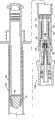
Fig. 1 is the rear view that has the preferred equipment of the present invention of attached pin and pin lid;
Fig. 2 is the exploded front perspective view of the equipment of Fig. 1;
Fig. 3 is the cross-sectional elevation view of the equipment of Fig. 1, wherein partial dismantling;
Fig. 4 is the cross-sectional elevation view of the equipment of Fig. 3, and wherein the pin lid is removed;
Fig. 5 is that the equipment of Fig. 1 is removing pin lid and the pin cross-sectional elevation view after being withdrawn in the syringe;
Fig. 6 is the cross-sectional side view of the plunger handle of Fig. 2;
Fig. 7 is that the plunger handle of Fig. 6 is extended most advanced and sophisticated amplification cross-sectional view forward;
Fig. 8 is the amplification view of the needle holder of Fig. 2;
Fig. 9 is the cross-sectional view of the needle holder cut open of the line 9-9 along Fig. 8;
Figure 10 is the amplification cross-sectional view of the injector cartridge of Fig. 2;
Figure 11 is the enlarged side view of the needle connector of Fig. 2;
Figure 12 is the left end view of the needle connector of Figure 11;
Figure 13 is the cross-sectional view of the needle connector cut open of the line 13-13 along Figure 12;
Figure 14 is the enlarged side view of the needle assembly of the needle connector that comprises Figure 12, pin and pin lid;
Figure 15 is the cross-sectional view of the needle assembly of Figure 14;
Figure 16 is the cross-section detail view of right end portion of the needle assembly of Figure 15;
Figure 17 is the cross-sectional view of the pin lid of Figure 15, and wherein needle connector and pin are removed;
Figure 18 decomposes side elevation view as the part of syringe among Fig. 1, but has anterior attachment (frontal attachment), and this front portion attachment is Luer insert but not needle assembly, for example, and in Fig. 2-4;
Figure 19 is the amplification cross-sectional view of the equipment of Figure 18, but shows the Luer insert that is connected to syringe;
Figure 20 is that the part of syringe among Fig. 1 is decomposed side elevation view, partial dismantling wherein, but have the anterior attachment that comprises valve; And
Figure 21 is the amplification cross-sectional view of the equipment of Figure 20, but shows the anterior attachment that is connected to syringe.
The specific embodiment
With reference to Fig. 1, disclosedpreferred equipment 20 of the present invention comprises and thebonded syringe 22 of anterior attachment that this front portion attachment is a needle assembly 24.With reference to Fig. 1 and in conjunction with the Fig. 2 as exploded view, thesyringe 22 ofequipment 20 preferably includes plunger assembly, and this plunger assembly further comprisesplunger handle 28, back connector 26, precedingconnector 30 and plunger seal 32.Plunger handle 28 inside betweenpro-connector 30 and the back connector 26 also are provided with a retraction cavity, and the partcylindrical shell 40 ofsyringe 22 also can be used as the part of this retraction cavity.Outlet (vent, passage) 23 is arranged near the rear portion of plunger handle ideally.
Syringe 22 also preferably includes retraction assemblies, and this retraction assemblies further comprisesneedle holder 36, retention means (retainer member) 34 and retraction spring 38.Retention means 34 preferably can be attached toneedle holder 36, andneedle holder 36 preferred parts can be inserted in the spring 38.During the manufacturing ofsyringe 22, retraction assemblies is preferably mounted in thecylindrical shell 40, and after this plunger assembly in the retraction assemblies back is installed tocylindrical shell 40.
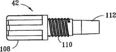
Needle assembly preferably includesneedle connector 42,pin 44 and pin lid 46.The preferred needle connector relatively ofpin 44 42 is fixed with fixed relationship, and the opposite end ofneedle connector 42 screws in the extension forward of band coupling screw thread of (thread into)needle holder 36 ideally, as following with reference to Fig. 3 and 4 descriptions.If desired,equipment 20 can be made with this form, and perhaps needle assembly can separately be packed and sell, and is attached tosyringe 22 at the use scene.
With reference to Fig. 3 and 4, the elastic component that retention means 34 is preferably independent, but also can be integrally moulded or form the part ofneedle holder 36, thereby between retention means,needle holder 36 andcylindrical shell 40, provide fluid-tight, and between pin retraction assemblies andplunger seal 32, set up fluid cavity thus, and also makespring 38 remain in compression by engaging with cylindrical shell 40.According to a particularly preferred embodiment of the present invention,needle holder 36 comprises slit or other structures that can engage with partcylindrical shell 40, thereby relatively rotating between opposing needle holder and the cylindrical shell, particularly needle assembly or other anterior attachments are attached to syringe with formingdevice 20 during.The outside ofpin lid 46 preferably slides within thefemale thread 54, to allowneedle connector 42 andneedle holder 36 bands to mate between the part of screw threads with threads engage, whereinpin 44 is attached on this needle connector with fixed relationship by viscose glue or other similar effective known methods.Thus, the endoporus ofpin 44 is placed as with theendoporus 48 ofneedle holder 36 and with the fluid cavity fluid ofneedle holder 36 back in thecylindrical shell 40 and is communicated with.Connector 30 is backward before the displacement before the precedingconnector 30 within the extension forward ofplunger handle 28 is when starting retraction when user, prevents that any fluid that is assigned in the syringe from entering in the retraction cavity part in the plunger handle.Cylindrical shell 40 is outward-dipping relatively ideally for the element ofprotectiveness safeguard structure 52; with before connecting anterior attachment or during reducepollute needle holder 36 extend most advanced and sophisticated probability forward; in this case, needle assembly comprisespin lid 46,pin 40 and needle connector 42.The inclined element ofprotectiveness safeguard structure 52 also helps to guide anterior attachment and aims at the front portion of needle holder 36.Afterneedle connector 42 is attached toneedle holder 36, and just before using,pin lid 46 ideally from the frictional engagement ofneedle connector 42 remove, as shown in Figure 4.
With reference to Fig. 5, inject fluid by aftersyringe 22,needle connector 42 and thepin 44, start the retraction ofpin 44 forward by forcing plunger handle 28 relativecylindrical shells 40, cause thus precedingconnector 30 anteriorcontact pin keeper 36 towards after part.When this takes place, precedingconnector 30 displacement backward, and the tip thatplunger handle 28 is extended forward contact and promotion retention means 34 move forward into ring-type recess 50, make retention means 34 break away from and allow thespring 38 of compression to forceneedle holder 36,needle connector 42 and pin 44 upwards to entersyringe 22 thus, no longer reach the position that can cause accidental needle sticks from the front portion ofcylindrical shell 40 at the front tip of thisposition pin 44 to such position from needle holder 36.When plunger handle 28 during in abutting connection withcylindrical shell 40 inboard, the hands of user is exerted pressure to back connector 26, the surface towards preceding to theflange part 64 that radially extends applies opposite finger strength simultaneously, can impel ideally to be forced into concave position in the back of the body opening of thecollar 62 around theperipheral element 66 at plunger handle 28 backs.Along withneedle holder 36 moves backward owing to the power ofspring 38, precedingconnector 30 also is forced upwardly in the chamber that enters in theplunger handle 28, and the intracavity air can be byoutlet 23 effusions.
Further illustrate, describe and explain other parts with reference to Fig. 6-17 with reference to the disclosed preferred equipment of Fig. 1-5.Fig. 6 discloses theretraction cavity 70 inplunger handle 28, theplunger handle 28 and the tip of extending forward ofplunger handle 28, this tip of extending forward further comprisesannular projection 42, this annular projection cooperates with shoulder 76 to limit arecess 74, and above-mentionedplunger seal 32 can be arranged in this recess provides fluid-tight with the inboard near injector cartridge.The open forward end ofarrow 78indication plunger handle 78, the precedingconnector 30 of Fig. 2 is positioned at wherein between erecting stage.With reference to Fig. 7, it illustrates the detail view of the step-like front end of having describedplunger handle 28 better, and wherein the surface 80 degree specific surfaces 82 that stretch out forward are big.The retraction force that such step is preferred for concentrating plunger handle the one side to be applied before to the opposite side application of force of retention means 34 helps retention means 34 is removed fromneedle holder 36 thus.
Fig. 8 further shows thecylindricality head 84 ofneedle holder 36, splittedannular shoulder 86,slit 90,slot wall Rule 58 of taper.The rear portion ofspring 38 discussed above is in abutting connection withshoulder 86, and the external diameter of the extension forward ofneedle holder 36 is slightly less than the internal diameter of thespring 38 of compression ideally, with the extension forward of the coil encircling needle holder that allows spring 38.With reference to Fig. 9, thefemale thread 92 within the part that comprises surface,Rule 58 forms fit dimension ideally and aims at, and engages with the corresponding external screw thread that receivesneedle connector 42, as mentioned above.Conical surface 100 is thesurface 112 ofjoint pin adapter 42 slidably ideally, and with reference to as described in Figure 11 and 12, andpassage needle holder 36 as following.
Figure 10 further disclose after-opening 60, the ring-type collar 62, thefinger flange 64 that can grip,female thread 54 andprotectiveness safeguard structure 52 forward with outwardly directed element.
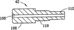
Figure 11-13 further discloses therib 108 that is provided with along circumference aroundneedle connector 42 front portions, thehole 106 of setting up the setting placed in the middle of the fluid path that passes through adapter,external screw thread 110 and taper guidingcomposition surface 112.
Figure 14-17 further discloses theblind end 115 ofrear end 116 and after-opening 122, the conicalouter wall part 114 of extending forward and pin lid 46.Beforeneedle connector 42 was attached tosyringe 22, as mentioned above, the rear end ofpin 44 was inserted in theelongate chamber 118 ofpin lid 46 ideally, and is attached to 106 inside, hole regularly by gluing or therelative needle connector 42 of othermodes.Needle connector 42 is the inwall of thepart 116 of frictionalengagement pin lid 46 ideally, its juncture is that the free end ofneedle connector 42 resides in thespace 120 of basic cylindricality, if more preferably provide as stand-alone assembly, then be packaged in the sterilization wrap material, up to screwing in the needle holder of syringe, as mentioned above whenneedle connector 42.
Figure 18-19 disclosesanterior attachment 126; this front portion attachment comprises Luerinsert 132,luer lock flange 134,pin 136 and finger grips 128,140; finger grips is used for the sealed engagement of Luer insert screw-in withfemale thread 54; wherein above-mentioned female thread in the front portion of thecylindrical shell 40 ofsyringe 122,protectiveness safeguard structure 52 back.Thesurface ridges 130 that can grip also is arranged on thesyringe 22 ideally, with the gripping during the connection that promotes attachment forwardly.The inner chamber 138 ofanterior attachment 126 provides the fluid between theinterior chamber 98 ofpin 136 andneedle connector 42 to be communicated with, as mentioned above.Still be held in place though comprise the retraction assemblies of retention means 34,needle holder 36 andspring 38,pin 136 can not retract in thesyringe 22 in this embodiment, and must reclaim or more preferably place sharp disposal container of permission.
Figure 20-21 discloses as theanterior attachment 142 with valve module of external screw-thread 144, and this external screw-thread also can be attached to thefemale thread 54 ofprotectiveness safeguard structure 52 back of cylindrical shell 40.In this embodiment, after use, do not need the pin of withdrawal.
For the person of ordinary skill of the art, when reading this description in conjunction with the accompanying drawings, other variations of the present invention and modification will become apparent equally, and purpose is that scope of the present invention disclosed herein is only limited by the broad interpretation of claims, and this what is claimed is the legal inventor's of giving.
Claims (16)
Translated fromChineseApplications Claiming Priority (3)
| Application Number | Priority Date | Filing Date | Title |
|---|---|---|---|
| US10757808P | 2008-10-22 | 2008-10-22 | |
| US61/107,578 | 2008-10-22 | ||
| PCT/US2009/059962WO2010047963A1 (en) | 2008-10-22 | 2009-10-08 | Universal syringe with retractable needle |
Publications (1)
| Publication Number | Publication Date |
|---|---|
| CN102176938Atrue CN102176938A (en) | 2011-09-07 |
Family
ID=42119608
Family Applications (1)
| Application Number | Title | Priority Date | Filing Date |
|---|---|---|---|
| CN200980140259.3APendingCN102176938A (en) | 2008-10-22 | 2009-10-08 | Universal syringe with retractable needle |
Country Status (7)
| Country | Link |
|---|---|
| US (2) | US8343094B2 (en) |
| EP (1) | EP2341962A1 (en) |
| JP (1) | JP5492902B2 (en) |
| CN (1) | CN102176938A (en) |
| AU (1) | AU2009307960A1 (en) |
| BR (1) | BRPI0920626A2 (en) |
| WO (1) | WO2010047963A1 (en) |
Families Citing this family (38)
| Publication number | Priority date | Publication date | Assignee | Title |
|---|---|---|---|---|
| BRPI0514909B8 (en) | 2004-09-03 | 2021-06-22 | L O M Laboratories Inc | safety-type syringe for use with a hypodermic needle |
| US9308353B2 (en) | 2010-07-29 | 2016-04-12 | Retractable Technologies, Inc. | Needle retraction apparatus |
| US9138545B2 (en)* | 2012-12-14 | 2015-09-22 | Retractable Technologies, Inc. | Needle retraction apparatus |
| US9381309B2 (en) | 2008-06-10 | 2016-07-05 | Retractable Technologies, Inc. | Frontal attachment device for syringe with pinch-activated retraction |
| JP5767208B2 (en) | 2010-03-29 | 2015-08-19 | テルモ株式会社 | Prefilled syringe |
| CN102525488B (en)* | 2011-12-01 | 2013-09-25 | 上海金塔医用器材有限公司 | Disposable sterile retraction safety blood sampling needle |
| US10272234B2 (en) | 2012-02-23 | 2019-04-30 | Unl Holdings Llc | Devices for targeted delivery of therapeutic implants |
| CN104582767B (en) | 2012-02-23 | 2018-11-06 | 尤尼特拉克特注射器控股有限公司 | Retracting Needle Safety Syringes |
| JP6109203B2 (en) | 2012-02-23 | 2017-04-12 | ユニトラクト シリンジ プロプライエタリイ リミテッドUnitract Syringe Pty Ltd | Instrument for targeted delivery of therapeutic implants |
| US9186466B2 (en) | 2012-03-14 | 2015-11-17 | Becton, Dickinson And Company | Passively activated safety needle assemblies and methods of use |
| BR112015010607A2 (en) | 2012-11-09 | 2017-12-05 | Iinjec Tech Inc | fluid delivery injector, retractable needle assembly, and method for injecting at least one dose of a transcutaneously fluid medication into the body. |
| US9956352B2 (en) | 2012-12-14 | 2018-05-01 | Retractable Technologies, Inc. | Combined medical device with sliding frontal attachment and retractable needle |
| USD823457S1 (en) | 2012-12-14 | 2018-07-17 | Retractable Technologies, Inc. | Blood collection tube holder with offset needle retraction chamber and frontal attachment |
| US9302055B2 (en) | 2012-12-14 | 2016-04-05 | Retractable Technologies, Inc. | Frontal attachment device for syringe with rotationally activated retractable needle |
| US9320469B2 (en) | 2012-12-14 | 2016-04-26 | Retractable Technologies, Inc. | Retractable needle for blood gas sampling |
| USD829891S1 (en) | 2012-12-14 | 2018-10-02 | Retractable Technologies, Inc. | Syringe with offset needle retraction chamber and frontal attachment |
| USD823463S1 (en) | 2012-12-14 | 2018-07-17 | Retractable Technologies, Inc. | Frontal attachment for medical device |
| US10568554B2 (en) | 2012-12-14 | 2020-02-25 | Retractable Technologies, Inc. | Blood collection tube holder with slide-activated needle retraction |
| USD823461S1 (en) | 2012-12-14 | 2018-07-17 | Retractable Technologies, Inc. | Slimline syringe with offset needle retraction chamber and frontal attachment |
| US9974941B2 (en)* | 2013-03-13 | 2018-05-22 | Joseph P. Schultz | Medical connector contamination prevention systems |
| USD1010114S1 (en) | 2013-03-13 | 2024-01-02 | Joseph P. Schultz | Medical connector contamination prevention device |
| EP4268866A3 (en) | 2013-09-06 | 2024-07-17 | Retractable Technologies, Inc. | Medical device with sliding frontal attachment and retractable needle |
| CN104688378A (en)* | 2015-01-22 | 2015-06-10 | 李丽容 | Universal needle device |
| CN104688377A (en)* | 2015-01-22 | 2015-06-10 | 李丽容 | Universally rotatable needle device |
| WO2017008850A1 (en) | 2015-07-15 | 2017-01-19 | Guangdong Intmed Medical Appliance Co., Ltd | Syringe with retractable needle |
| US10032949B2 (en)* | 2015-11-09 | 2018-07-24 | International Business Machines Corporation | Photovoltaic device based on Ag2ZnSn(S,Se)4 absorber |
| US11173253B2 (en) | 2016-12-12 | 2021-11-16 | Becton, Dickinson And Company | Packaging for safety needle |
| US11103651B2 (en) | 2016-12-13 | 2021-08-31 | Beckon, Dickinson and Company | Safety needle devices |
| US10814073B2 (en) | 2016-12-13 | 2020-10-27 | Becton, Dickinson And Company | Safety device with collapsible housing and trigger activation |
| US10918801B2 (en) | 2016-12-13 | 2021-02-16 | Becton, Dickinson And Company | Caps for integrated fill and inject of safety needle devices |
| US10661026B2 (en) | 2016-12-13 | 2020-05-26 | Becton, Dickinson And Company | Safety needle device |
| US10792439B2 (en) | 2016-12-13 | 2020-10-06 | Becton, Dickinson And Company | Safety needle devices |
| US10589036B2 (en) | 2016-12-13 | 2020-03-17 | Becton, Dickinson And Company | Safety needle device |
| US11083847B2 (en) | 2018-01-26 | 2021-08-10 | Becton, Dickinson And Company | Flush syringe with flip cap |
| CN109789270A (en) | 2018-08-30 | 2019-05-21 | 江苏采纳医疗科技有限公司 | Safety injector |
| US11298467B2 (en)* | 2019-02-27 | 2022-04-12 | Retractable Technologies, Inc. | Syringe with multifunctional needle holder and retainer ring assembly |
| US11975168B2 (en) | 2019-11-18 | 2024-05-07 | Becton, Dickinson And Company | Disinfectant cap |
| US12029828B2 (en) | 2020-03-05 | 2024-07-09 | Becton, Dickinson And Company | Disinfection cap |
Family Cites Families (46)
| Publication number | Priority date | Publication date | Assignee | Title |
|---|---|---|---|---|
| US1668315A (en) | 1926-06-21 | 1928-05-01 | George N Hein | Coupling and locking device for syringes |
| BE426856A (en) | 1937-04-14 | |||
| US4123091A (en) | 1977-11-21 | 1978-10-31 | Renal Systems, Inc. | Tube connector |
| US4326569A (en) | 1980-02-15 | 1982-04-27 | Critikon, Inc. | Stopcock seal |
| US4624393A (en) | 1981-07-02 | 1986-11-25 | Survival Technology, Inc. | Split hub assembly for a necked down cartridge tube |
| US4490142A (en) | 1983-08-22 | 1984-12-25 | Silvern Rubin D | Carpule syringe with rapidly acting mechanism for controllably _positively retaining the hub of a hypodermic needle |
| US4718463A (en) | 1985-12-20 | 1988-01-12 | Mallinckrodt, Inc. | Method of producing prefilled sterile plastic syringes |
| US4743233A (en) | 1986-01-23 | 1988-05-10 | Schneider Medical Technologies, Inc. | Safety cap syringe |
| US4747835A (en) | 1987-02-19 | 1988-05-31 | Jeffrey Sandhaus | Safety device for hypodermic needles |
| US4838869A (en)* | 1987-08-29 | 1989-06-13 | Allard Edward F | Retractable needle syringe |
| US5205833A (en) | 1988-02-22 | 1993-04-27 | Harsh Don J | Device for removing hypodermic needles from syringe barrels |
| US5694686A (en) | 1991-12-18 | 1997-12-09 | Icu Medical, Inc. | Method for assembling a medical valve |
| CA2124822C (en) | 1991-12-18 | 2007-07-03 | George A. Lopez | Medical valve |
| US5624414A (en) | 1992-02-18 | 1997-04-29 | St. Francis Research Institute | Needleless straight infusion port |
| JPH06181985A (en) | 1992-09-18 | 1994-07-05 | Takeda Chem Ind Ltd | Pre-filled syringe |
| AU5745494A (en) | 1992-12-14 | 1994-07-04 | Mallinckrodt Medical, Inc. | Pre-filled, sterilized syringe and method of making |
| US5322515A (en)* | 1993-03-15 | 1994-06-21 | Abbott Laboratories | Luer adapter assembly for emergency syringe |
| CA2135706C (en)* | 1993-11-15 | 1999-06-15 | Walter E. Cover | Retractable-needle cannula insertion set with refinements to better control leakage, retraction speed, and reuse |
| US5419775A (en) | 1994-01-18 | 1995-05-30 | Allergan, Inc. | Syringe flange adapter and method |
| US5531699A (en) | 1994-09-19 | 1996-07-02 | Abbott Laboratories | Spring-loaded reciprocable stylet holder |
| AUPM922394A0 (en) | 1994-11-03 | 1994-11-24 | Astra Pharmaceuticals Pty Ltd | Plastic syringe with overcap |
| US5616136A (en) | 1995-01-09 | 1997-04-01 | Med-Safe Systems, Inc. | Quick release needle removal apparatus |
| US6090077A (en)* | 1995-05-11 | 2000-07-18 | Shaw; Thomas J. | Syringe plunger assembly and barrel |
| US5573516A (en)* | 1995-09-18 | 1996-11-12 | Medical Connexions, Inc. | Needleless connector |
| US5807343A (en) | 1996-09-30 | 1998-09-15 | Becton Dickinson And Company | Protective sealing barrier for a syringe |
| US5782803A (en) | 1996-11-26 | 1998-07-21 | Jentzen; S. William | Low dead space, interchangeable needle syringe |
| DE19717033A1 (en) | 1997-04-23 | 1998-11-12 | Schott Glas | Needle cap for a prefillable disposable syringe |
| US5919169A (en) | 1997-06-23 | 1999-07-06 | Grams; Guenter | Cannula lock and seal mechanism |
| US6217550B1 (en) | 1998-07-29 | 2001-04-17 | Becton, Dickinson And Company | Single-use syringe |
| US7014622B1 (en)* | 1999-02-18 | 2006-03-21 | Medsafe Technologies, Llc | Interchangeable needle safety syringe |
| US6382204B1 (en) | 1999-10-14 | 2002-05-07 | Becton Dickinson And Company | Drug delivery system including holder and drug container |
| US6517516B1 (en)* | 1999-10-15 | 2003-02-11 | Becton Dickinson And Company | Method of making a retracting needle syringe |
| JP2001112867A (en) | 1999-10-18 | 2001-04-24 | Terumo Corp | Syringe containing drug |
| CA2382459C (en)* | 1999-11-29 | 2009-12-29 | Mdc Investment Holdings, Inc. | Combination safety needle assembly and medical apparatus |
| JP3591636B2 (en) | 2000-04-03 | 2004-11-24 | ニプロ株式会社 | Prefilled syringe |
| US6547764B2 (en) | 2000-05-31 | 2003-04-15 | Novo Nordisk A/S | Double pointed injection needle |
| JP2002263186A (en) | 2001-03-09 | 2002-09-17 | Takeda Chem Ind Ltd | Gasket for bypass type pre-filled syringe |
| US7867215B2 (en) | 2002-04-17 | 2011-01-11 | Carmel Pharma Ab | Method and device for fluid transfer in an infusion system |
| CN2628071Y (en) | 2003-05-08 | 2004-07-28 | 比特克生化科技股份有限公司 | Syringe reservoir |
| US7280618B2 (en) | 2003-06-25 | 2007-10-09 | Interdigital Technology Corporation | Digital baseband receiver including a high pass filter compensation module for suppressing group delay variation distortion incurred due to analog high pass filter deficiencies |
| HK1077154A2 (en) | 2003-12-30 | 2006-02-03 | Icu Medical, Inc. | Valve assembly |
| US7510545B2 (en)* | 2005-02-09 | 2009-03-31 | B. Braun Medical Inc. | Needleless access port valves |
| EA200600319A1 (en) | 2006-02-21 | 2007-06-29 | Чих-Куанг Хсу | SAFE SYRINGE |
| US9295790B2 (en) | 2006-05-05 | 2016-03-29 | Retractable Technologies, Inc. | Syringe with recessed nose and protective guard for use with frontal attachments |
| RO123580B1 (en) | 2006-05-05 | 2014-01-30 | Retractable Technologies, Inc. | Syringe with embedded nose to be used with frontal connecting attachments |
| US8128605B2 (en)* | 2007-12-24 | 2012-03-06 | Mentor Worldwide Llc | Syringe for use in medical applications |
- 2009
- 2009-10-08CNCN200980140259.3Apatent/CN102176938A/enactivePending
- 2009-10-08BRBRPI0920626Apatent/BRPI0920626A2/ennot_activeIP Right Cessation
- 2009-10-08JPJP2011533220Apatent/JP5492902B2/ennot_activeExpired - Fee Related
- 2009-10-08AUAU2009307960Apatent/AU2009307960A1/ennot_activeAbandoned
- 2009-10-08WOPCT/US2009/059962patent/WO2010047963A1/enactiveApplication Filing
- 2009-10-08EPEP09822415Apatent/EP2341962A1/ennot_activeWithdrawn
- 2010
- 2010-07-15USUS12/837,228patent/US8343094B2/enactiveActive
- 2012
- 2012-09-11USUS13/610,427patent/US8636688B2/enactiveActive
Also Published As
| Publication number | Publication date |
|---|---|
| US8343094B2 (en) | 2013-01-01 |
| WO2010047963A1 (en) | 2010-04-29 |
| EP2341962A1 (en) | 2011-07-13 |
| JP5492902B2 (en) | 2014-05-14 |
| AU2009307960A1 (en) | 2010-04-29 |
| JP2012506295A (en) | 2012-03-15 |
| BRPI0920626A2 (en) | 2015-12-22 |
| US8636688B2 (en) | 2014-01-28 |
| US20130006190A1 (en) | 2013-01-03 |
| US20100286604A1 (en) | 2010-11-11 |
Similar Documents
| Publication | Publication Date | Title |
|---|---|---|
| CN102176938A (en) | Universal syringe with retractable needle | |
| CN100400120C (en) | Fluid transfer adapters for use with syringe barrels | |
| US10426703B2 (en) | Vial adapters | |
| US8114050B2 (en) | Controlled retraction syringe and plunger therefor | |
| US4675005A (en) | Retractable disposable syringe | |
| US5180370A (en) | Safety hypodermic syringe with retractable needle | |
| US5024616A (en) | Disposable sheath for hypodermic cannula used with a syringe | |
| US4040421A (en) | Hypodermic syringe and attached needle assembly | |
| US7955300B2 (en) | Disposable safety syringe with retractable needle | |
| WO1991000750A1 (en) | Disposable hypodermic syringe with retractable needle | |
| MXPA06004718A (en) | Self-locking safety disposable syringe with needle protection after use. | |
| BRPI0407060B1 (en) | ACTIVABLE RETRACTABLE NEEDLE SET FOR USE WITH A SYRINGE CYLINDER SET | |
| JPH1080494A (en) | Assembly of catheter adapter | |
| US5968019A (en) | Safety syringe | |
| US10406295B2 (en) | Retainer for retractable needle assemblies and syringes | |
| US20140088513A1 (en) | Modular gas-actuated retractable needle assembly | |
| AU2003255605A1 (en) | Disposable injection device designed to be pre-filled | |
| JP2019536566A5 (en) | ||
| CA2409297C (en) | Retractable needle and syringe combination | |
| US20030093037A1 (en) | Hypodermic syringes | |
| CN100522271C (en) | single use syringe | |
| CN100515510C (en) | Disposable Safety Syringes | |
| WO2003072162A2 (en) | Probe-activated medicament injector device | |
| CN100394991C (en) | Retractable Safety Syringes | |
| US7074207B2 (en) | Safety syringe |
Legal Events
| Date | Code | Title | Description |
|---|---|---|---|
| C06 | Publication | ||
| PB01 | Publication | ||
| C10 | Entry into substantive examination | ||
| SE01 | Entry into force of request for substantive examination | ||
| REG | Reference to a national code | Ref country code:HK Ref legal event code:DE Ref document number:1159538 Country of ref document:HK | |
| AD01 | Patent right deemed abandoned | Effective date of abandoning:20110907 | |
| C20 | Patent right or utility model deemed to be abandoned or is abandoned | ||
| REG | Reference to a national code | Ref country code:HK Ref legal event code:WD Ref document number:1159538 Country of ref document:HK |