CN102164734B - Apparatus and methods for digital manufacturing - Google Patents
Apparatus and methods for digital manufacturingDownload PDFInfo
- Publication number
- CN102164734B CN102164734BCN200980137301.6ACN200980137301ACN102164734BCN 102164734 BCN102164734 BCN 102164734BCN 200980137301 ACN200980137301 ACN 200980137301ACN 102164734 BCN102164734 BCN 102164734B
- Authority
- CN
- China
- Prior art keywords
- predetermined
- subsystem
- constituent elements
- printhead
- selectively
- Prior art date
- Legal status (The legal status is an assumption and is not a legal conclusion. Google has not performed a legal analysis and makes no representation as to the accuracy of the status listed.)
- Expired - Fee Related
Links
Images


Classifications
- B—PERFORMING OPERATIONS; TRANSPORTING
- B29—WORKING OF PLASTICS; WORKING OF SUBSTANCES IN A PLASTIC STATE IN GENERAL
- B29C—SHAPING OR JOINING OF PLASTICS; SHAPING OF MATERIAL IN A PLASTIC STATE, NOT OTHERWISE PROVIDED FOR; AFTER-TREATMENT OF THE SHAPED PRODUCTS, e.g. REPAIRING
- B29C64/00—Additive manufacturing, i.e. manufacturing of three-dimensional [3D] objects by additive deposition, additive agglomeration or additive layering, e.g. by 3D printing, stereolithography or selective laser sintering
- B29C64/10—Processes of additive manufacturing
- B29C64/106—Processes of additive manufacturing using only liquids or viscous materials, e.g. depositing a continuous bead of viscous material
- B29C64/112—Processes of additive manufacturing using only liquids or viscous materials, e.g. depositing a continuous bead of viscous material using individual droplets, e.g. from jetting heads
- Y—GENERAL TAGGING OF NEW TECHNOLOGICAL DEVELOPMENTS; GENERAL TAGGING OF CROSS-SECTIONAL TECHNOLOGIES SPANNING OVER SEVERAL SECTIONS OF THE IPC; TECHNICAL SUBJECTS COVERED BY FORMER USPC CROSS-REFERENCE ART COLLECTIONS [XRACs] AND DIGESTS
- Y10—TECHNICAL SUBJECTS COVERED BY FORMER USPC
- Y10T—TECHNICAL SUBJECTS COVERED BY FORMER US CLASSIFICATION
- Y10T156/00—Adhesive bonding and miscellaneous chemical manufacture
- Y10T156/17—Surface bonding means and/or assemblymeans with work feeding or handling means
- Y—GENERAL TAGGING OF NEW TECHNOLOGICAL DEVELOPMENTS; GENERAL TAGGING OF CROSS-SECTIONAL TECHNOLOGIES SPANNING OVER SEVERAL SECTIONS OF THE IPC; TECHNICAL SUBJECTS COVERED BY FORMER USPC CROSS-REFERENCE ART COLLECTIONS [XRACs] AND DIGESTS
- Y10—TECHNICAL SUBJECTS COVERED BY FORMER USPC
- Y10T—TECHNICAL SUBJECTS COVERED BY FORMER US CLASSIFICATION
- Y10T29/00—Metal working
- Y10T29/49—Method of mechanical manufacture
- Y10T29/49826—Assembling or joining
- Y—GENERAL TAGGING OF NEW TECHNOLOGICAL DEVELOPMENTS; GENERAL TAGGING OF CROSS-SECTIONAL TECHNOLOGIES SPANNING OVER SEVERAL SECTIONS OF THE IPC; TECHNICAL SUBJECTS COVERED BY FORMER USPC CROSS-REFERENCE ART COLLECTIONS [XRACs] AND DIGESTS
- Y10—TECHNICAL SUBJECTS COVERED BY FORMER USPC
- Y10T—TECHNICAL SUBJECTS COVERED BY FORMER US CLASSIFICATION
- Y10T428/00—Stock material or miscellaneous articles
- Y10T428/249921—Web or sheet containing structurally defined element or component
Landscapes
- Chemical & Material Sciences (AREA)
- Engineering & Computer Science (AREA)
- Materials Engineering (AREA)
- Physics & Mathematics (AREA)
- Manufacturing & Machinery (AREA)
- Mechanical Engineering (AREA)
- Optics & Photonics (AREA)
- Automatic Assembly (AREA)
Abstract
Translated fromChineseDescription
Translated fromChinese背景技术Background technique
本发明总体上涉及制造物体/材料,更具体地,涉及数字化制造。The present invention relates generally to the fabrication of objects/materials, and more particularly to digital fabrication.
由于传统的制造技术实际上是连续的,所以大多数传统的制造技术可以算是模拟的,它们的基础结构不能任意指定并且每次测量和随后的应用精度都会损失。Since most traditional manufacturing techniques can be considered analog because they are virtually continuous, their underlying structure cannot be specified arbitrarily and precision is lost for each measurement and subsequent application.
传统的三维印刷工艺通常依赖于材料并且不可逆转。典型地,传统的三维数字打印机使用连续的材料,数字化规格由外部逻辑施加。传统的三维制造是加式或减式的。加式传统三维打印机是通过将无定形材料以产生三维结构的方式沉积和/或粘合在一起来工作的。减式三维制造,例如用车床或计算机数控铣床进行的三维制造,是通过从一块大体积材料上移除材料来工作的。这些技术使用复杂的控制系统以精确地定位作业的工具以准确地构建所需物体。基质确定成品的材料和表面特性,但不确定它的形状,对于加式工艺,基质通常是粉末和粘合剂,对于减式工艺,基质通常是原材料块。Traditional 3D printing processes are usually material dependent and irreversible. Typically, conventional 3D digital printers use a continuous stream of material, with digitization specifications imposed by external logic. Traditional 3D manufacturing is additive or subtractive. Additive conventional 3D printers work by depositing and/or bonding amorphous materials together in a way that creates a three-dimensional structure. Subtractive 3D manufacturing, such as that performed with a lathe or computer numerically controlled milling machine, works by removing material from a bulky piece of material. These techniques use complex control systems to precisely position the working tools to build exactly the desired object. The matrix determines the material and surface properties of the finished product, but not its shape. For additive processes, the matrix is usually powders and binders. For subtractive processes, the matrix is usually a block of raw materials.
现有的无模制造(Freeform Fabrication)主要是模拟的加式三维打印,因为大多数现有的装配器通过将少量的一种或两种不同的材料分为尺寸非常精确的微滴并且在非常精确的位置进行分配来构建结构。大多数现有的商业无模制造打印机通过将少量的数种昂贵材料合放在一起来构建。为了制造高分辨率的物体,它们需要非常精确,因此它们的花费在数万及数十万美元之间,并且必须由熟练的技术人员操作。Existing Freeform Fabrication is mainly simulated additive 3D printing, because most existing assemblers divide a small amount of one or two different Precise locations are assigned to build structures. Most existing commercial dieless manufacturing printers build by putting together small amounts of several expensive materials. To make high-resolution objects, they need to be very precise, so they cost between tens and hundreds of thousands of dollars and must be operated by skilled technicians.
本领域中的现有技术通常使用几种工艺中的其中一种。在一种方法中,通过沉积第一层流体多孔材料或多孔固体构造构成要素。接着,将粘合剂材料沉积至所选区域以生成材料层。第二种方法包括:装上有材料供应的可移动分配头,该材料在预定温度或暴露于光或紫外光时凝固。其他装置将细丝而不是分配的滴状物置于所需位置,然后加热细丝以使它的一部分变成可流动液体,该可流动液体在那个位置凝固。第三种方法包含由具有预定构造的各层制造材料制造三维物体。连续层以预定顺序堆叠并固定到一起以形成物体。改良包括从两种不同类别的材料生成部件,其中第一类材料形成由第一类材料和第二类材料的界面定义的三维形状。The prior art in this field generally uses one of several processes. In one method, the constituent elements are constructed by depositing a first layer of fluid porous material or porous solid. Next, an adhesive material is deposited onto the selected areas to create a layer of material. The second method involves mounting a movable dispensing head with a supply of material that solidifies at a predetermined temperature or upon exposure to light or ultraviolet light. Other devices place a filament rather than a dispensed drop at the desired location, then heat the filament to turn a portion of it into a flowable liquid that solidifies at that location. A third method involves fabricating a three-dimensional object from layers of fabrication material having a predetermined configuration. Successive layers are stacked and fastened together in a predetermined order to form the object. The refinement includes generating the part from two different classes of materials, where the first class of materials forms a three-dimensional shape defined by the interface of the first class of materials and the second class of materials.
最近的制造技术,例如自下而上(bottom-up)的自组装对它们由构成要素之间的相互作用所引导的自发组装材料的能力提供了数字化带来的一些好处;然而,自组装工艺可能难于控制并且一般仅限于规则、半周期或随机结构。自上而下确定的拾-放方法提供了对生产的精确控制并且在少量构成要素以特定方式组装时是有用的。然而,自上而下的组装方法受限于它们的产量和小规模并且通常限于两个维度。已经尝试协调不同的组装模式,例如按等级划分、定向的以及模板化的自组装。基于选择性固化的最新的快速原型制造技术使自上而下制造任意复杂的结构成为可能,但是其不能处理预制的构造块;所以,它们仅限于少量具有相互兼容的流变性质的均质材料。Recent fabrication techniques such as bottom-up self-assembly offer some of the benefits of digitalization in their ability to spontaneously assemble materials guided by interactions between constituent elements; however, self-assembly processes Can be difficult to control and generally limited to regular, semi-periodic or stochastic structures. A top-down determined pick-and-place approach provides precise control over production and is useful when a small number of components are assembled in a specific manner. However, top-down assembly methods are limited by their throughput and small scale and are generally limited to two dimensions. Attempts have been made to harmonize different modes of assembly, such as hierarchical, directed, and templated self-assembly. State-of-the-art rapid prototyping techniques based on selective solidification enable the top-down fabrication of arbitrarily complex structures, but they cannot handle prefabricated building blocks; therefore, they are limited to a small number of homogeneous materials with mutually compatible rheological properties .
已经描述了用于从数字化材料创造三维物体的数字化装配器,其中新的一行送入装配头并被添加到结构,但这种技术受限于其产量。需要一种能较快生产以及使规模增加,同时还获得精确输出的数字化制造系统。Digital assemblers have been described for creating three-dimensional objects from digitized materials, where a new row is fed into the assembly head and added to the structure, but this technique is limited in its throughput. There is a need for a digital manufacturing system that can produce faster and scale up while still obtaining accurate output.
发明内容Contents of the invention
在一个实施例中,本发明的用于制造物体/材料的方法包括(a)以预定排列将预定构成要素排列在预定区域,(b)选择性移除至少两个排列的预定构成要素,该选择性移除实质上同时并且依据预定的移除方案发生,以及(c)根据预定的放置方案,实质上同时将选择性移除的构成要素放置在预定位置。在一个示例中,重复步骤(a)-(c)直到制造出物体/材料。在一个实施例中,本发明的用于制造物体/材料的系统包括:接收多个构成要素并将接收的构成要素排列在进料器区域的构成要素排列子系统,一个排列中的位置对应一个构成要素的位置,包括打印头结构化子系统的装配头,打印头结构化子系统的一个表面具有多个可选择性激活的位置,每个可选择性激活的位置对应于排列中的一个位置;一旦激活,将打印头结构化子系统置于排列的构成要素上后,一个构成要素即可操作地附着于一个选择性激活的位置;将打印头结构子系统从供料器区域移开后,可操作地附着的构成要素从排列中移除;以及用于从多个可选择性激活的位置选择性地激活位置的激活子系统;在该实施例中,系统还包括控制打印头结构子系统运动的运动控制部件,运动包含将打印头结构子系统置于排列的构成要素上,将打印头结构子系统从供料器区域移开以及将打印头结构子系统置于构建整备区上的位置。In one embodiment, the method for manufacturing an object/material of the present invention comprises (a) arranging predetermined constituent elements in a predetermined arrangement in a predetermined area, (b) selectively removing at least two of the arranged predetermined constituent elements, the The selective removal occurs substantially simultaneously and according to a predetermined removal scheme, and (c) substantially simultaneously placing the selectively removed constituent elements in a predetermined location according to a predetermined placement scheme. In one example, steps (a)-(c) are repeated until an object/material is fabricated. In one embodiment, the system for fabricating objects/materials of the present invention includes: a component alignment subsystem that receives a plurality of components and arranges the received components in the feeder area, a position in an array corresponds to a The location of the constituent elements, including the assembly head of the printhead structuring subsystem, a surface of the printhead structuring subsystem has a plurality of selectively activatable locations, each selectively activatable location corresponding to a location in the arrangement ;once activated, a component is operatively attached to a selectively activated position after placing the printhead structuring subsystem on an arrayed component; after removing the printhead structuring subsystem from the feeder area , an operably attached constituent element is removed from the arrangement; and an activation subsystem for selectively activating a location from a plurality of selectively activatable locations; in this embodiment, the system also includes a control printhead structure sub-system The motion control component of the system movement that includes placing the printhead structure subsystem on the arrayed components, moving the printhead structure subsystem away from the feeder area, and placing the printhead structure subsystem on the build staging area Location.
在本发明的系统的一个实施例中,打印头包括打印头结构化部件;打印头结构化部件的表面具有多个可选择性激活的位置,每个可选择性激活的位置对应于排列中的一个位置;用于使用预定方案将可选择性激活的位置实质上均匀润湿的润湿部件,所选的预定方案是为了将表面置于排列的多个构成要素上后,将构成要素可操作地附着于实质上均匀润湿的可选择性激活的位置,以及用于选择性地干燥预定的可选择性激活的位置的可控的干燥部件,预定的可选择性激活的位置对应于预定的构成要素移除方案。为了更好地理解本发明以及本发明的其他和更多目的,请参考附图和详细的说明书,并且,本发明的范围将在权利要求中限定。In one embodiment of the system of the present invention, the printhead comprises a printhead structural part; the surface of the printhead structural part has a plurality of selectively activatable positions, each selectively activatable position corresponding to a A location; a wetted member for substantially uniformly wetting a selectively activatable location using a predetermined protocol selected to render the elements operable after placing a surface on an array of elements Attached to a substantially uniformly wetted selectively activatable location, and a controllable drying member for selectively drying a predetermined selectively activatable location corresponding to a predetermined Component removal options. For a better understanding of the present invention and other and further objects of the invention, reference is made to the drawings and detailed description, and the scope of the invention will be defined in the claims.
附图说明Description of drawings
图1a、1b是本发明的方法的实施例的流程示意图;Fig. 1a, 1b are the schematic flow charts of the embodiment of the method of the present invention;
图2a-2g描述了执行本发明的方法的实施例所获得的示例性结果;Figures 2a-2g depict exemplary results obtained by performing an embodiment of the method of the present invention;
图3a-3d是由本发明的方法的实施例制造的示例性物体;图4是本发明的系统的实施例的示意图;Figures 3a-3d are exemplary objects fabricated by an embodiment of the method of the present invention; Figure 4 is a schematic diagram of an embodiment of the system of the present invention;
图5a-5i是本发明的系统的实施例中使用的体素(voxels,三维像素构成要素的物理示例)的示例性实施例;Figures 5a-5i are exemplary embodiments of voxels (physical examples of three-dimensional pixel constituent elements) used in embodiments of the system of the present invention;
图5j-5k是使用本发明的方法制造的物体的示例性实施例;Figures 5j-5k are exemplary embodiments of objects fabricated using the methods of the present invention;
图6a-6d是本发明的印刷头的一个实施例的操作的示意图;Figures 6a-6d are schematic illustrations of the operation of one embodiment of the printhead of the present invention;
图7a-7e是本发明的印刷头的实施例的操作的示例性实施例的示意图;Figures 7a-7e are schematic illustrations of an exemplary embodiment of the operation of an embodiment of a printhead of the present invention;
图8是本发明的印刷头的另一个实施例的示意图;以及Figure 8 is a schematic diagram of another embodiment of the printhead of the present invention; and
图9是本发明的系统的另一个实施例的示意图。Figure 9 is a schematic diagram of another embodiment of the system of the present invention.
具体实施方式Detailed ways
以下公开了数字化制造系统和方法的实施例。这里所使用的体素或构成要素是指三维像素或基本数字化构造块的物理实例。Embodiments of digital manufacturing systems and methods are disclosed below. A voxel or constituent, as used herein, refers to a physical instance of a three-dimensional pixel or basic digital building block.
图1a示出了本发明的方法的一个实施例的流程图。参考图1a,给出了构成要素(体素)并且这些构成要素以预定的排列排列在预定区域(步骤10)。选择性地移除两种或更多的排列的构成要素,该移除实质上同时发生并且依据预定移除方案进行(步骤20)。根据预定的放置方案,将选择性移除的构成要素实质上同时置于预定位置(步骤30)。如果物体/材料尚未完成,那么重复步骤10到30。Figure 1a shows a flow chart of one embodiment of the method of the present invention. Referring to FIG. 1a, constituent elements (voxels) are given and arranged in a predetermined arrangement in a predetermined area (step 10). Two or more arrayed constituent elements are selectively removed substantially simultaneously and according to a predetermined removal scheme (step 20). According to a predetermined placement scheme, the selectively removed constituent elements are placed at predetermined locations substantially simultaneously (step 30). If the object/material is not complete, then repeat
当移除/放置方案仅需要仅移除/放置一个构成要素时,从排列中仅移除一个构成要素并且仅将一个构成要素放置在整备区中的位置。在一个示例中,通过自组装来完成构成要素(体素)的排列。在一个实施例中,通过使用重力和振动实现自组装。应当注意的是,其他自组装方法也在本发明的范围内。例如但不限于也可以使用依靠毛细管力的自组装方法(例如见Uthara Srinivasan,Dorian Liepmann和Roger T.Howe,Microstructure toSubstrate Self-Assembly Using Capillary Forces,Journal ofMicroelectromechanical Systems,Vol.10,No.1,March 2001;Smith,J.S,High density,low parasitic direct integration by fluidic self assembly(F SA),2000.IEDM Technical Digest.International Electron Devices Meeting,2000,Pages:201-204,公开号为20070092654的美国专利,将其全部内容作为参考引用于此),或依靠静电力的自组装方法(例如,见Joe Tien,AndreasTerfort和George M.Whitesides,Microfabrication through ElectrostaticSelf-Assembly,Langmuir 1997,13,5349-5355,将其全部内容作为参考引用于此)。When the removal/placement scenario requires only one component to be removed/placed, only one component is removed from the arrangement and only one component is placed in place in the staging area. In one example, the arrangement of the constituent elements (voxels) is accomplished by self-assembly. In one embodiment, self-assembly is achieved through the use of gravity and vibration. It should be noted that other methods of self-assembly are also within the scope of the present invention. For example, but not limited to, self-assembly methods relying on capillary forces can also be used (see for example Uthara Srinivasan, Dorian Liepmann and Roger T. Howe, Microstructure to Substrate Self-Assembly Using Capillary Forces, Journal of Microelectromechanical Systems, Vol.10, No.1, March 2001; Smith, J.S, High density, low parasitic direct integration by fluidic self assembly (F SA), 2000. IEDM Technical Digest. International Electron Devices Meeting, 2000, Pages: 201-204, U.S. Patent Publication No. 20070092654, will The entire contents of which are incorporated herein by reference), or self-assembly methods relying on electrostatic forces (for example, see Joe Tien, Andreas Terfort and George M.Whitesides, Microfabrication through Electrostatic Self-Assembly, Langmuir 1997, 13, 5349-5355, all of which The content is hereby incorporated by reference).
应当注意的是,其他排列构成要素的方法也在本发明的范围内,例如但不限于:手动放置、使用拾-放机器人放置、将构成要素安放入区域凹进、将构成要素浮动在毛细管吸引力点上,或料斗为传送带送料。It should be noted that other methods of arranging components are also within the scope of the present invention, such as but not limited to: manual placement, placement using a pick-and-place robot, placing components into area recesses, floating components on capillary tubes Attraction points, or hoppers, feed the conveyor belt.
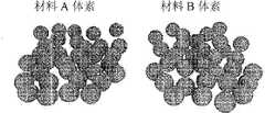
尽管在此处公开的示例性实施例中,构成要素是实质上球形的构成要素,但其他各种构成要素形状也在本发明的范围内。在一些实施例中,构成要素(体素)可以包括但不限于:具有选自等边三角形、矩形、菱形、六边形、不规则的二维和镶嵌形状,以及由上述形状的组合构成的连锁区域的横截面的圆柱形构成要素(2.5维构成要素),以及例如但不限于是矩形棱柱、截顶四面体或截顶正八面体的三维构成要素。Although in the exemplary embodiments disclosed herein, the constituent elements are substantially spherical constituent elements, various other constituent element shapes are also within the scope of the present invention. In some embodiments, constituent elements (voxels) may include, but are not limited to: a voxel having a shape selected from the group consisting of equilateral triangles, rectangles, rhombuses, hexagons, irregular two-dimensional and tessellated shapes, and combinations thereof. Cylindrical constituents (2.5-dimensional constituents) of the cross-section of the interlocking region, and three-dimensional constituents such as, but not limited to, rectangular prisms, truncated tetrahedrons, or truncated regular octahedrons.
在一些示例中,监控构成要素的排列和/或选择性移除两个或更多排列的构成要素和/或实质上同时放置选择性移除的构成要素,以确保正确执行。In some examples, the arrangement of constituent elements is monitored and/or selectively removed of two or more arranged constituent elements and/or the selectively removed constituent elements are placed substantially simultaneously to ensure proper performance.
在一些实施例中,也可以使用另一种类型的构成要素。在一组实施例中,其他类型的构成要素是牺牲性的构成要素。在那些实施例中,(在将一组将留在物体中的构成要素排列后或同时)获得了牺牲性构成要素的排列。获得了牺牲性构成要素的排列后,为牺牲性构成要素的排列执行图1a的步骤20和步骤30。当物体被完全组装后,移除牺牲性构成要素。本发明不仅限于这些实施例,例如,牺牲性元件的移除可以通过以下方式实现:选择融化温度比正常构成要素低的牺牲性构成要素以及将已完成物体的温度升高至大于牺牲性构成要素的融化温度,选择可以被特定溶剂溶解的牺牲性构成要素,而正常的构成要素不会被溶剂溶解,选择使用特定的粘合剂时不牢固附着至其他构成要素、而使用该特定的粘合剂时正常的构成要素将牢固地附着的牺牲性构成要素,并且提供振动力以松散和移除牺牲性构成要素。应当注意的是,移除牺牲性构成要素的其他方法也在本发明的范围内。In some embodiments, another type of component may also be used. In one set of embodiments, other types of constituents are sacrificial constituents. In those embodiments, an arrangement of sacrificial constituents is obtained (after or simultaneously with the arrangement of a set of constituents to remain in the object). Having obtained the arrangement of the sacrificial constituent elements, steps 20 and 30 of FIG. 1 a are performed for the arrangement of the sacrificial constituent elements. When the object is fully assembled, the sacrificial constituent elements are removed. The invention is not limited to these embodiments, for example, the removal of the sacrificial element can be achieved by selecting a sacrificial constituent with a lower melting temperature than the normal constituent and raising the temperature of the completed object to a temperature greater than that of the sacrificial constituent. The melting temperature of the selected sacrificial components can be dissolved by a specific solvent, while the normal components will not be dissolved by the solvent, the selection of a specific adhesive will not firmly adhere to other components, and the use of the specific adhesive The normal constituents will firmly adhere to the sacrificial constituents when dosed, and a vibratory force is provided to loosen and remove the sacrificial constituents. It should be noted that other methods of removing sacrificial constituents are also within the scope of the present invention.
图1b示出了本发明的方法的另一个实施例的流程图。参考图1b,要制造的物体或材料的设计图被转换成一系列的位图(图2a),其描述了每层中特定体素类型的存在与否(提供了放置/移除方案),(步骤B)。将预制的多种材料的体素(图2b)倒入供料器并且(步骤C)排列(在一实施例中,单一材料的体素利用托盘中的重力和振动自对齐)成每种材料的有序晶格(图2c)(步骤D)。选择性激活的沉积工具根据位图从整层体素、体素的有序晶格实质上同时拾起所选择的体素(图2d),并将它们堆叠在构建整备区上(图2e)(步骤E)。为每层的每种材料重复步骤C到E。如果使用牺牲性体素,一旦整个物体(图2f)装配完成(步骤F),那么将移除牺牲性支撑材料以创建无模结构(图2g)。Fig. 1b shows a flow chart of another embodiment of the method of the present invention. Referring to Fig. 1b, the blueprint of the object or material to be fabricated is converted into a series of bitmaps (Fig. 2a), which describe the presence or absence of specific voxel types in each layer (providing placement/removal schemes), ( Step B). Prefabricated voxels of multiple materials (Figure 2b) are poured into the feeder and (step C) aligned (in one embodiment, voxels of a single material self-align using gravity and vibration in the tray) into each material ordered lattice of (Fig. 2c) (step D). Selectively activated deposition tools pick up selected voxels substantially simultaneously from the entire layer of voxels, an ordered lattice of voxels according to the bitmap (Fig. 2d) and stack them on the build staging area (Fig. 2e) (step E). Repeat steps C through E for each material in each layer. If sacrificial voxels are used, once the entire object (Fig. 2f) is assembled (step F), the sacrificial support material is removed to create a model-free structure (Fig. 2g).
在该过程的各个步骤中,监控该过程以确定合适的执行。在一个示例中,监控预定的构成要素-一种材料类型的体素的排列。在另一个示例中,对从排列中实质上同时移除一种材料类型的至少两个体素进行监控。在又一个示例中,对实质上同时放置移除的一种材料类型的体素进行监控。At various steps in the process, the process is monitored to determine proper execution. In one example, a predetermined constituent - an arrangement of voxels of a material type - is monitored. In another example, substantially simultaneous removal of at least two voxels of a material type from the array is monitored. In yet another example, voxels of one material type are monitored for placement and removal at substantially the same time.
在一个示例中,放置(也称为沉积)所选的构成要素通过使允许拾起所选构成要素的机构无效来实现。激活后,所选构成要素沉积在构建整备区,将要沉积的第一组构成要素沉积在该区上,将下一组构成要素沉积在之前沉积的那一组上面。在一个示例中,通过在构建整备区上要沉积构成要素的位置分配粘合剂来实现该无效。将装配(拾起)头放置在构建整备区上并从构建整备区移开装配(拾起)头之后,可操作地附着于装配头的构成要素即被分离和沉积。In one example, placing (also referred to as depositing) the selected constituent is accomplished by deactivating the mechanism that allows the selected constituent to be picked up. When activated, the selected constituents are deposited on the build staging area, the first set of constituents to be deposited is deposited on this area, and the next set of constituents is deposited on top of the previously deposited set. In one example, this inactivation is achieved by dispensing adhesive on the build staging area where the constituent elements are to be deposited. After placing the assembly (pickup) head on the build staging area and removing the assembly (pickup) head from the build staging area, the constituent elements operatively attached to the assembly head are separated and deposited.
在一个实施例中,正在制造的物体/材料将由多层多种类型的构成要素组成。这里可以是任意数量的不同类型的构成要素,并且每层可以由多种类型的构成要素的一种或多种组成。正在制造的物体/材料将由预定数量的层组成,并且这里可以是任意数量的层。每层的构成可以是不同的。重复步骤10-30(图1)多次,重复的次数最多不超过构成要素的类型数量。每层完成后,将预定位置的位置调整为适合于制造物体/材料的下一层的位置。然后重复步骤10-30以及调整预定位置的位置的步骤多次,重复的次数等于正在制造的物体/材料中的层数。In one embodiment, the object/material being fabricated will consist of multiple layers of various types of building elements. There may be any number of different types of constituent elements, and each layer may be composed of one or more of the various types of constituent elements. The object/material being fabricated will consist of a predetermined number of layers, and here may be any number of layers. The composition of each layer can be different. Repeat steps 10-30 (FIG. 1) multiple times, and the number of repetitions does not exceed the number of types of constituent elements at most. After each layer is completed, the position of the predetermined location is adjusted to be suitable for the position of the next layer of the manufactured object/material. Steps 10-30 and adjusting the position of the predetermined position are then repeated a number of times equal to the number of layers in the object/material being fabricated.
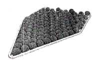
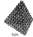
图3a-3d是由本发明的方法的实施例所制造的示例性物体。Figures 3a-3d are exemplary objects fabricated by embodiments of the method of the present invention.
在一个实施例中,本发明的系统包括:接收一种材料类型的多个构成要素以及将构成要素排列在供料区域的构成要素排列子系统,排列中的一个位置对应于来自构成要素排列的一个构成要素的位置,具有打印头结构化子系统的装配头,打印头结构化子系统的一个表面(该表面将被置于构成要素排列上)具有多个可选择性激活的位置,每个可选择性激活的位置对应于构成要素排列中的一个位置。一旦激活,将打印头结构化子系统置于构成要素排列上之后,即可将多个构成要素(体素)中的一个构成要素可操作地附着至一个可选择性激活的位置;一旦将印刷头结构化子系统从供料区域移开,可操作地附着的构成要素就从排列移除。装配头还包括用于从多个可选择性激活的位置中选择性地激活位置的激活子系统。本发明的系统的上述实施例还包括控制打印头结构化子系统的运动的运动控制子系统,其中运动包括将打印头结构化子系统置于构成要素上,将打印头结构化子系统从供料区域移开以及将打印头结构化子系统放置在构建整备区上的位置。在一个示例中,本发明的系统的实施例还包括无效子系统。在已经将打印头结构化子系统置于构建整备区上的位置之后,无效子系统将可操作地附着于打印头结构化子系统的构成要素分离并且将分离的构成要素沉积在构建整备区的位置上。In one embodiment, the system of the present invention includes: a component alignment subsystem that receives a plurality of constituents of a material type and arranges the constituents in a feed area, a position in the array corresponding to a component from the array of constituents The location of a constituent element, the assembly head with the printhead structuring subsystem, a surface of the printhead structuring subsystem that will be placed on the array of constituent elements, has a plurality of selectively activatable locations, each An optionally activatable position corresponds to a position in the arrangement of constituent elements. Once activated, one of a plurality of constituent elements (voxels) can be operably attached to a selectively activatable position after the printhead structuring subsystem is positioned over the array of constituent elements; As the head structuring subsystem moves away from the feed area, the operably attached components are removed from the array. The assembly head also includes an activation subsystem for selectively activating a location from a plurality of selectively activatable locations. The above-described embodiment of the system of the present invention also includes a motion control subsystem that controls movement of the printhead structuring subsystem, wherein the movement includes placing the printhead structuring subsystem on a constituent element, moving the printhead structuring subsystem from a supply The material area is removed and the printhead structuring subsystem is placed on the build staging area. In one example, an embodiment of the system of the present invention also includes an invalidation subsystem. After the printhead structuring subsystem has been placed in position on the build staging area, the deactivation subsystem detaches the constituent elements operably attached to the printhead structuring subsystem and deposits the detached constituent elements on the build staging area position.
在一个示例中,本发明并不限于该示例,无效子系统包括将粘合剂分配在构建整备区位置上的粘合剂分配部件;其中,将装配头置于构建整备区上的位置后,一旦将打印头结构化子系统从构建整备区移开,可操作地附着于打印头结构化子系统的构成要素即与打印头结构化子系统分离并且沉积在构建整备区的位置上。In one example, and the invention is not limited to this example, the invalidation subsystem includes an adhesive dispensing component that dispenses adhesive at a build staging location; wherein, after placing the assembly head at a location on the build staging area, Once the printhead structuring subsystem is removed from the build staging area, the constituent elements operably attached to the printhead structuring subsystem are detached from the printhead structuring subsystem and deposited in place on the build staging area.
在另一个示例中,本发明并不限于该示例,多个构成要素中的每一个是连锁构成要素。在将打印头结构化子系统放置在构建整备区上的位置后,可操作地附着于打印头结构化子系统的构成要素即与已经沉积在构建整备区上的构成要素连锁,该连锁将可操作地附着的构成要素分开。一旦将打印头结构化子系统从构建整备区移开,分开的构成要素将沉积在构建整备区上。In another example, the present invention is not limited to this example, each of a plurality of constituent elements is a chain constituent element. After the printhead structuring subsystem is placed in position on the build staging area, the components operably attached to the printhead structuring subsystem are interlocked with the components already deposited on the build staging area, the linkage will be The operatively attached constituent elements are detached. Once the printhead structuring subsystem is removed from the build staging area, the separate constituent elements will be deposited on the build staging area.
在一个实施例中,本发明并不限于该实施例,构成要素排列子系统包括接收构成要素(体素)的供料器容器和接收构成要素后使供料器容器振动的振动产生部件。在一个示例中,供料器容器是倾斜的以利用重力和振动用于排列的自组装。In one embodiment, the present invention is not limited to this embodiment, the component arrangement subsystem includes a feeder container receiving the component (voxel) and a vibration generating part that vibrates the feeder container after receiving the component. In one example, the feeder container is tilted to utilize gravity and vibration for self-assembly of the array.
应当注意的是,使用其他自组装方法的构成要素排列子系统也在本发明的范围内。例如,使用例如但不限于依靠毛细管力的自组装方法或依靠静电力的自组装方法的构成要素排列子系统也在本发明的范围内。It should be noted that component array subsystems using other self-assembly methods are also within the scope of the present invention. For example, it is also within the scope of the invention to use component alignment subsystems using methods such as, but not limited to, self-assembly by means of capillary forces or self-assembly by means of electrostatic forces.
还应当注意的是,使用其他排列构成要素的方法的构成要素排列子系统也在本发明的范围内,例如但不限于手动放置、通过使用拾-放机器人放置、将构成要素安放入区域凹进处、将构成要素浮动在毛细管吸引力点上,或料斗为传送带送料。It should also be noted that component arranging subsystems using other methods of arranging components are also within the scope of the invention, such as, but not limited to, manual placement, placement by use of a pick-and-place robot, placement of components into area recesses. Inlets, floating components over capillary points of attraction, or hoppers to feed conveyor belts.
在一个实施例中,装配头(也称为打印头)包括打印头结构化部件,打印头结构化部件的表面具有多个可选择性激活的位置,每个可选择性激活的位置都是对应于构成要素排列中的一个位置的区域。在该实施例中,装配头还包括润湿子系统和干燥子系统。润湿子系统使用预定液体将每个区域实质上均匀地润湿,选择该预定液体以使一旦将表面置于构成要素上,即可操作地将构成要素附着于实质上均匀润湿的区域。可控的干燥子系统选择性地干燥预定区域,该预定区域对应于预定的构成要素移除方案。在一个示例中,预定液体包含水和清洁剂。应当注意的是,这里使用的“液体”包括凝胶剂并且其他液体也在本发明的范围内。In one embodiment, the assembly head (also referred to as the printhead) comprises a printhead structural part, the surface of the printhead structural part has a plurality of selectively activatable locations, each selectively activatable location is a corresponding An area at a position in an array of constituent elements. In this embodiment, the assembly head also includes a wetting subsystem and a drying subsystem. The wetting subsystem wets each area substantially uniformly with a predetermined liquid selected to operatively attach the constituent to the substantially uniformly wetted area once the surface is placed on the constituent. A controllable drying subsystem selectively dries predetermined areas corresponding to predetermined constituent element removal protocols. In one example, the predetermined liquid includes water and detergent. It should be noted that "liquid" as used herein includes gels and other liquids are within the scope of the present invention.
在一个示例中,可控的干燥子系统包括光学系统,其将对应于预定的构成要素移除方案中不移除区域的图像投影至装配头的表面上。电磁辐射源为光学系统提供源,选择源的波长和强度以便实质上干燥与预定的构成要素移除方案对应的预定区域。应当注意的是,该可激活区域可以是凹进区域。In one example, the controllable drying subsystem includes an optical system that projects images onto a surface of the assembly head that correspond to areas not to be removed in a predetermined component removal scheme. A source of electromagnetic radiation provides a source for the optical system, the wavelength and intensity of the source being selected to substantially dry a predetermined area corresponding to a predetermined constituent removal protocol. It should be noted that the activatable area may be a recessed area.
在另一个实施例中,装配头(也称为打印头)包括打印头结构化部件,打印头结构化子系统的表面具有多个可选择性激活的位置,每个可选择性激活的位置对应于体素排列中的一个位置,以及实质上为可选择性激活的位置中的预定位置提供电荷的充电子系统。In another embodiment, an assembly head (also referred to as a printhead) includes a printhead structural component, the surface of the printhead structural subsystem has a plurality of selectively activatable locations, each selectively activatable location corresponding to A location in the voxel arrangement, and a charging subsystem that substantially provides charge to a predetermined one of the selectively activatable locations.
在一个示例中,充电子系统包括提供了离子流的电晕充电子系统,其中离子流提供了电荷,以及用于防止对预定的可选择性激活的位置充电的选择性阻断/放电子系统。在一个示例中,选择性阻断/放电子系统包括在预定的可选择性激活的位置和离子流之间提供物理屏障的遮蔽物,该物理屏障防止对预定的可选择性激活的位置充电。在另一个示例中,充电子系统包括提供导向预定的可选择性激活的位置的电磁辐射的光学子系统,该可选择性激活的位置由经预定波长/强度的电磁辐射照射后即放电的材料组成。In one example, the charging subsystem includes a corona charging subsystem that provides a flow of ions that provides the charge, and a selective blocking/discharging subsystem for preventing charging of predetermined selectively activatable sites . In one example, the selective blocking/discharging subsystem includes a shield that provides a physical barrier between the predetermined selectively activatable location and the flow of ions, the physical barrier preventing charging of the predetermined selectively activatable location. In another example, the charging subsystem includes an optical subsystem that provides electromagnetic radiation directed at a predetermined selectively activatable site consisting of a material that discharges when irradiated with electromagnetic radiation of a predetermined wavelength/intensity. composition.
在一个实施例中,每个构成要素(体素)包含实质上为球形的构成要素。在另一个实施例中,每个构成要素(体素)可以是圆柱形构成要素,其具有从等边三角形、矩形、菱形、六边形、不规则的二维和镶嵌形形状,以及包含上述形状的组合的连锁区域、矩形棱柱、截钉四面体或截顶正八面体中选择的截面区域。In one embodiment, each constituent element (voxel) comprises a substantially spherical constituent element. In another embodiment, each constituent element (voxel) may be a cylindrical constituent element having shapes ranging from equilateral triangles, rectangles, rhombuses, hexagons, irregular two-dimensional and tessellated shapes, and including the above A cross-sectional area selected from a combination of interlocking areas of shapes, rectangular prisms, truncated tetrahedra, or truncated octahedrons.
为了更好地说明本发明,以下公开了多个示例性实施例。图4示出了使用球形体素和使用了润湿子系统的打印头的实施例的示意图。打印头(50)在移动轴X(55)上来回移动。投影仪(60)通过聚焦光学器件(70)发光以选择性地烘干打印头。润湿台(75)允许在队列形供料器(80)排成一行时整个头被润湿并且为了拾起保持体素层。经过检查台(85)后,每层被放置在沿着移动轴Z移动的构建整备区(90)上。控制电子器件(95)指挥整个流程。In order to better illustrate the present invention, several exemplary embodiments are disclosed below. Figure 4 shows a schematic diagram of an embodiment of a printhead using spherical voxels and using a wetting subsystem. The print head (50) moves back and forth on the movement axis X (55). A projector (60) emits light through focusing optics (70) to selectively dry the printheads. The wetting station (75) allows the entire head to be wetted while the queue feeder (80) is lined up and holds the voxel layer for pick-up. After passing the inspection table ( 85 ), each layer is placed on a build staging area ( 90 ) moving along the axis of movement Z. Control electronics (95) direct the entire process.
沉积打印头50在X轴上以自由度55移动至一系列的台(B-E)。台A是暴露台,在此选择性干燥由投影仪60产生并通过一系列透镜65缩放的光图案而发生。下部的摄像头实时监控干燥过程。台B是润湿台70,在该示例性实施例中,选择性干燥发生之前,打印头的整个表面在此被浸没在水和清洁剂的溶液中。台C是材料供料器80。将原材料(球)倒入后面的供料器,并且这两个进料器都是倾斜的,在该示例性实施例中,约为3度(应当注意的是,为示例性实施例提供的特定数值和特性不是对本发明的限制)。将(产生机械振动的)呼叫器马达嵌入每个供料器并且振动以将球体放入能量最低的位置,其与靠近的晶格对应。在实质上同时进行的装配过程中,选择性拾起预对齐层中任意位置的体素的能力是有用的。在每个供料器下面安装摄像机,进料器具有透明基座以使摄像机可以使用机器视觉技术实时监控每个球体的位置。检查台85还包含下部的摄像机,其在将球体沉积于构建整备区90之前和之后检查沉积头。这可以对实际沉积的球体进行间接验证。构建整备区只保持住正在装配的部分,并且当随后的层被堆叠时,在Z轴上以自由角度(H)向下移动。在一个示例中,控制电子器件95提供USB接口(其他接口和实施例也在本发明的范围内)至主计算机,该主计算机控制负责运动系统和摄像头图像采集的微控制器。
尽管本发明的系统的上述示例性实施例和图2a-2f所示的实施例使用球形构成要素(体素),但所使用的特定构成要素并不是对本发明的限制。图5a-5i示出了可以使用的示例性的各种构成要素(体素)(但应当再次注意的是,这里示出的示例性的各种体素不是对本发明的限制)。Although the above-described exemplary embodiments of the system of the present invention and the embodiments shown in Figures 2a-2f use spherical building blocks (voxels), the specific building blocks used are not limiting of the invention. Figures 5a-5i show exemplary various building blocks (voxels) that may be used (but again it should be noted that the exemplary various voxels shown here are not limiting of the invention).
以下公开了图4所示的示例性实施例的操作。首先,在由多个二进制位图组成的蓝图中表达数字化物体,二进制位图对应于将要打印的物理材料的连续层。位图中的每一位发出信号表示目标物体(图2a)的特定层中特定物理体素类型存在与否。然后,预制的适当类型的体素被分配进入材料供料器托盘(图2b)。接着,单一材料的体素利用托盘中的重力和振动自动对齐(图2c)。直到达到完美的二维六边形排列,球体才固定下来。在一个不是限制本发明的示例中,直径为1.5mm的球形体素被放置在55-单元的三角形托盘中。在示例性实施例中,不同材料的两种球体被分开对齐。本发明的制造过程可以扩展到更大的层、更小的体素以及任意数量的材料。The operation of the exemplary embodiment shown in FIG. 4 is disclosed below. First, digitized objects are represented in blueprints composed of multiple binary bitmaps that correspond to successive layers of the physical material to be printed. Each bit in the bitmap signals the presence or absence of a particular physical voxel type in a particular layer of the target object (Fig. 2a). Then, prefabricated voxels of the appropriate type are dispensed into the material feeder tray (Fig. 2b). Next, the voxels of the single material are automatically aligned using gravity and vibration in the tray (Fig. 2c). The spheres are not fixed until a perfect two-dimensional hexagonal arrangement is achieved. In an example not limiting the invention, spherical voxels with a diameter of 1.5 mm were placed in a 55-unit triangular tray. In an exemplary embodiment, two spheres of different materials are aligned separately. The fabrication process of the present invention can be extended to larger layers, smaller voxels, and any number of materials.
然后,如下所示,按顺序打印并堆叠模型的每一层。在示例性实施例中,一旦单一材料的均匀层已经自对齐(图2c),就应用平行毛细管光电流体作用以通过选择性润湿过程选择性地拾取由电子位图指定的体素(图2d)。首先,平面打印头包含与晶格位置对应的可激活位置的图案(110,图6a)。在图6a-6d所示的实施例中,每个可激活位置都是凹进的区域并且通过将具有可激活位置图案110的表面浸没到润湿子系统120中而被均匀地润湿(图6a)。在一个示例中,使用混合有清洁剂的水溶液作为润湿液(应当注意的是,包括凝胶剂的其他液体也在本发明的范围内)。选择用于润湿的液体以便得到良好的润湿性能。然后,体素的位图被转换成黑白圆点图,每个圆点与打印头的单元格对应。然后,通过使用适当的光学器件,将该图像投影至吸收红外线的沉积头上,在该示例性实施例中,使用具有高红外线发光汞弧灯(电磁辐射源的一个示例性实施例)的DLP投影仪130(光学系统的一个示例性实施例)。应当注意的是,其他光学系统和电磁辐射源也在本发明的范围内。干燥期望的单元图案(在一个不是对本发明限制的示例性实施例中,大约为45秒),让剩下的单元格润湿,或激活。Then, print and stack each layer of the model in order as shown below. In an exemplary embodiment, once the homogeneous layer of a single material has self-aligned (Fig. 2c), parallel capillary photohydrodynamic action is applied to selectively pick up voxels specified by the electronic bitmap through a selective wetting process (Fig. 2d ). First, the planar printhead contains a pattern of activatable locations corresponding to lattice locations (110, Figure 6a). In the embodiment shown in Figures 6a-6d, each activatable site is a recessed area and is uniformly wetted by immersing the surface with the pattern of
为了沉积体素(图2d),选择性润湿的打印头向下压在对齐的球体上。激活的凹进中的水将其各自的球体周围润湿,通过表面张力将其保持在适当位置。然后提起沉积头并且仅将这些选择的球体搬移至构建整备区。在构建过程中,使用液体聚醋酸乙烯酯粘合剂暂时地将结构粘合在一起。将粘合剂层涂在现有的打印物体上,并且沉积当前层。每个球体落入其下面的三个球体的空隙区域,并且当沉积头移开时,由粘合剂的粘结特性保持。To deposit voxels (Fig. 2d), a selectively wetted printhead is pressed down on aligned spheres. Water in the activated recesses wets around their respective spheres, holding them in place by surface tension. The deposition head is then lifted and only these selected spheres are moved to the build staging area. During construction, a liquid polyvinyl acetate adhesive was used to temporarily hold the structure together. The adhesive layer is applied to the existing printed object and the current layer is deposited. Each sphere falls into the void area of the three spheres below it and is held by the cohesive properties of the adhesive as the deposition head moves away.
在图7a-7e所示的具体示例中,选择圆点图案(图7a),干燥打印头上的这些单元(图7b),让其它的润湿或激活(图7c)。提起体素(图7d)并放置在构建整备区上(图7e)。In the specific example shown in Figures 7a-7e, the pattern of dots is selected (Figure 7a), those cells on the printhead are dried (Figure 7b), and others are wetted or activated (Figure 7c). Lift the voxel (Figure 7d) and place on the build staging area (Figure 7e).
以下公开了本发明的打印头的另一个实施例。参考图8,打印头的结构化子系统的表面具有多个可选择性激活的位置140,每个可选择性激活的位置对应于体素排列中的一个位置。在图8所示的实施例中,该结构化子系统还包括可以隔离或对地线层充电的隔离层150,地线层160,以及用于将打印头安装到X-Z区域的刚性主体170。打印头系统还包括实质上为可选择性激活的位置中预定的位置提供电荷的充电子系统(180,图9)以及防止对预定的可选择性激活的位置充电的选择性阻断/放电子系统。Another embodiment of the print head of the present invention is disclosed below. Referring to Figure 8, the surface of the structured subsystem of the printhead has a plurality of selectively
在一个示例中,充电子系统180包括提供离子流的电晕充电子系统,以及防止对预定的可选择性激活的位置充电的选择性阻断/放电子系统,其中离子流提供了电荷。在一个示例中,使用电晕丝在打印头表面提供静电。为了获得选择性电荷,在期望的单元和电晕发射器之间放置物理屏障。In one example, charging subsystem 180 includes a corona charging subsystem that provides a flow of ions that provide the charge, and a selective blocking/discharging subsystem that prevents charging of predetermined selectively activatable locations. In one example, a corona wire is used to provide static electricity on the printhead surface. To obtain selective charge, a physical barrier is placed between the desired cell and the corona emitter.
在另一个示例中(未示出),选择性阻断/放电子系统包括提供导向预定的可选择性激活的位置的电磁辐射的光学子系统,可选择性激活的位置由经预定波长/强度的电磁辐射照射后即放电的材料(例如,但不限于硒)组成。In another example (not shown), the selective blocking/discharging subsystem includes an optical subsystem that provides electromagnetic radiation directed at predetermined selectively activatable sites by a predetermined wavelength/intensity Composition of materials (such as, but not limited to, selenium) that discharge upon exposure to electromagnetic radiation.
图9示出了本发明的系统的示例性实施例的示意图,其中打印头利用静电充电。参考图9,打印头结构化子系统175移动至静电台180,在所示的实施例中(其他实施例也在本发明的范围内),封装在下面的电晕丝发射离子流以将静电提供至打印头结构化子系统的体素阵列(140,图8)Figure 9 shows a schematic diagram of an exemplary embodiment of the system of the present invention in which the printhead is charged electrostatically. Referring to Figure 9, the printhead structuring subsystem 175 moves to the electrostatic station 180, in the embodiment shown (other embodiments are also within the scope of the invention), the underlying corona wire emits a stream of ions to dissipate the electrostatic Voxel array (140, Figure 8) provided to printhead structuring subsystem
在图4和图9所示的示例性实施例中,使用了监控子系统。使用监控子系统以用于,例如但不限于:监控构成要素(体素)的排列,监控可操作地附着的构成要素的移除,以及监控分离的构成要素的放置。在一个示例中,由利用传统的机器视觉系统的机器视觉闭环监控体素在供料器中的自排列。在一个示例中,在示例性实施例的自对齐过程中,对于确保每个球体已获得了晶格内的明确位置,机器视觉是重要的。错误被描述为特征,并且可以在软件或整个重试流程中解决。In the exemplary embodiment shown in Figures 4 and 9, a monitoring subsystem is used. The monitoring subsystem is used for, for example and without limitation, monitoring the arrangement of constituent elements (voxels), monitoring the removal of operably attached constituent elements, and monitoring the placement of detached constituent elements. In one example, the self-alignment of the voxels in the feeder is monitored by machine vision closed loop using conventional machine vision systems. In one example, during the self-alignment process of the exemplary embodiments, machine vision is important to ensure that each sphere has acquired a well-defined position within the lattice. Errors are characterized and can be resolved in software or in the overall retry flow.
在另一个示例中,在示例性实施例中,自对齐过程可以在闭环中执行。供料器是倾斜的和振动的,然后,获取一帧并分析。当所有球体处于理想晶格位置的特定阈值内时,算法退出。否则,该算法选择继续振动,或将所有球体清空回到供料器中重新设定供料器。在另一个监控子系统的示例性应用中,机器视觉子系统检查沉积头实际保持哪些球体。该步骤在沉积步骤之前和之后的拾起操作之后发生。通过差分化这两个步骤出现的球体,可以推断哪些被沉积。In another example, in the exemplary embodiment, the self-alignment process may be performed in a closed loop. The feeder is tilted and vibrated, then, a frame is acquired and analyzed. The algorithm exits when all spheres are within a certain threshold of ideal lattice positions. Otherwise, the algorithm chooses to continue vibrating, or empty all spheres back into the feeder to reset the feeder. In another exemplary application of the monitoring subsystem, the machine vision subsystem checks which spheres are actually held by the deposition head. This step occurs after the pick-up operation before and after the deposition step. By differentiating the spheres that emerge from these two steps, it is possible to infer which ones were deposited.
监控子系统还可以用于在使用润湿的打印头的实施例中监控对所选择的润湿区域的干燥。The monitoring subsystem may also be used to monitor drying of selected wetted areas in embodiments using wetted printheads.
应当注意的是,在与本发明同类型的实施例中,可以使用材料的不同组合,例如但不限于金属和非金属材料。可以获得无模结构。在一个不是对本发明限制的示例性实施例中,使用不锈钢和丙烯酸球形构成要素(体素),其中丙烯酸球形构成要素作为牺牲性支撑材料。一旦完成装配,结果就是烧结该结构,以烧掉丙烯酸构成要素并且使不锈钢体素结合。It should be noted that in embodiments of the same type as the present invention, different combinations of materials may be used, such as but not limited to metallic and non-metallic materials. A moldless structure can be obtained. In one exemplary embodiment, which is not limiting of the invention, stainless steel and acrylic spherical constituents (voxels) were used, with the acrylic spherical constituents as sacrificial support material. Once assembled, the result was sintering the structure to burn off the acrylic constituents and bond the stainless steel voxels.
本发明的方法和系统可以用于制造各种物体/材料。可以获得复杂结构的制造原型。以下公开了本发明的方法和系统制造的物体/材料的其他示例性实施例,但不是全部。The methods and systems of the present invention can be used to fabricate various objects/materials. Manufacturing prototypes of complex structures can be obtained. Other exemplary embodiments of objects/materials produced by the methods and systems of the present invention, but not all, are disclosed below.
电网。本发明的方法和系统可以用于制造非常紧凑的、集成的三维电网和微机器人。使用少量导电的、绝缘的、晶体管和其他电子元件体素,可以在利用流体冷却通道一步制造紧凑型定制的三维集成电路。通过包括用于检测和驱动的压电或形状记忆合金体素,用来制造任何形式的机器人的所有构成要素都处在适当的位置,除了电源。流体网络。可以开发一个具有微流控功能的小型体素库以使用于化学和生物应用的三维集成微流体电路成为可能。在一个示例中,创建任意的三维流体网络仅需要两种体素类型(例如,见使用如图5h和5i所示的体素的图5j)。兼容的阀系统和传感方案不仅能够快速地制造三维微流体,并且还消除了传统微制造实验室中对齐各个层的高花费和难度。power grid. The method and system of the present invention can be used to fabricate very compact, integrated three-dimensional electrical grids and microrobots. Using a small number of conductive, insulating, transistor, and other electronic component voxels, compact custom 3D integrated circuits can be fabricated in one step using fluid cooling channels. By including piezoelectric or shape memory alloy voxels for sensing and actuation, all the building blocks to make any form of robot are in place, except for the power source. fluid network. A library of small voxels with microfluidic capabilities could be developed to enable three-dimensional integrated microfluidic circuits for chemical and biological applications. In one example, only two voxel types are required to create an arbitrary three-dimensional fluid network (eg, see Figure 5j using voxels as shown in Figures 5h and 5i). Compatible valve systems and sensing schemes not only enable rapid fabrication of 3D microfluidics, but also eliminate the high expense and difficulty of aligning individual layers in conventional microfabrication laboratories.
光子学。本发明的方法和系统还可以有益于光子学研究的前沿。当前,存在许多将开创计算新纪元的三维光学电路模拟,但不存在容易制造它们的方法。通常,通过在较大的矩阵中任意规则地放置高和低的光学指数元件来制造光学电路。可以使用体素(等级:1,000mm)验证这些微波属性,并且当体素的尺寸接近可见光的波长(等级:0.5mm)时,本发明的方法和系统可以提供制造光学电路的能力(例如见图5k)。photonics. The methods and systems of the present invention can also benefit the frontiers of photonics research. Currently, there are many 3D optical circuit simulations that will usher in a new era of computing, but no easy way to fabricate them exists. Typically, optical circuits are fabricated by arbitrarily regular placement of high and low optical index elements in a larger matrix. These microwave properties can be verified using voxels (scale: 1,000mm), and when the size of the voxel is close to the wavelength of visible light (scale: 0.5mm), the method and system of the present invention can provide the ability to fabricate optical circuits (see, for example, Fig. 5k).
智能体素:体素无需由单一材料组成;体素可能是可以根据电子蓝图拾起和放下的任意微型瓦。体素作为制造构建块的灵活性使得本发明的制造方法和系统超过只是无源材料的制造。例如,可以将微处理器、传感器和致动器嵌入“智能体素”以允许制造三维集成有源装置,例如微型机器人和三维电路。塑造成适当体素的生物材料可以允许根据组织工程应用的需要制造异形组织。Smart voxels: A voxel need not consist of a single material; a voxel could be an arbitrary tiny tile that can be picked up and put down according to an electronic blueprint. The flexibility of the voxel as a manufacturing building block allows the fabrication methods and systems of the present invention to go beyond the fabrication of passive materials only. For example, microprocessors, sensors, and actuators can be embedded in "smart voxels" to allow the fabrication of three-dimensional integrated active devices such as microrobots and three-dimensional circuits. Biomaterials shaped into appropriate voxels could allow the fabrication of heteromorphic tissues as desired for tissue engineering applications.
并行生产不相容的材料:本发明的方法和系统允许使用单个打印头实质上同时操控多种体素类型。尽管这里示出的物体和体素的示例性实施例相对简单,但本发明的方法和系统可以用于获得可调整的材料特性。Parallel Production of Incompatible Materials: The methods and systems of the present invention allow the manipulation of multiple voxel types substantially simultaneously using a single printhead. Although the exemplary embodiments of objects and voxels shown here are relatively simple, the methods and systems of the present invention can be used to obtain adjustable material properties.
应当注意的是,分析指出由本发明的方法和系统制造的物体的尺寸误差增长慢于与它的尺寸成比例的增长。该亚线性误差等级是由于体素不精确往往相互抵消的事实。It should be noted that the analysis indicates that the dimensional error of an object manufactured by the method and system of the present invention grows slower than proportional to its size. This level of sub-linear error is due to the fact that voxel-wise inaccuracies tend to cancel each other out.
尽管已经就各种实施例对本发明进行了描述,但应当意识到本发明还能有各种各样在从属权利要求的精神和范围内的更进一步以及其他实施例。While the invention has been described in terms of various embodiments, it should be realized that the invention is capable of various further and other embodiments within the spirit and scope of the appended claims.
Claims (41)
Translated fromChineseApplications Claiming Priority (3)
| Application Number | Priority Date | Filing Date | Title |
|---|---|---|---|
| US13700808P | 2008-07-25 | 2008-07-25 | |
| US61/137,008 | 2008-07-25 | ||
| PCT/US2009/051671WO2010011911A2 (en) | 2008-07-25 | 2009-07-24 | Apparatus and methods for digital manufacturing |
Publications (2)
| Publication Number | Publication Date |
|---|---|
| CN102164734A CN102164734A (en) | 2011-08-24 |
| CN102164734Btrue CN102164734B (en) | 2014-06-11 |
Family
ID=41570880
Family Applications (1)
| Application Number | Title | Priority Date | Filing Date |
|---|---|---|---|
| CN200980137301.6AExpired - Fee RelatedCN102164734B (en) | 2008-07-25 | 2009-07-24 | Apparatus and methods for digital manufacturing |
Country Status (3)
| Country | Link |
|---|---|
| US (1) | US8996155B2 (en) |
| CN (1) | CN102164734B (en) |
| WO (1) | WO2010011911A2 (en) |
Families Citing this family (36)
| Publication number | Priority date | Publication date | Assignee | Title |
|---|---|---|---|---|
| EP1609206B1 (en) | 2003-03-04 | 2010-07-28 | Rohm and Haas Electronic Materials, L.L.C. | Coaxial waveguide microstructures and methods of formation thereof |
| US7656256B2 (en) | 2006-12-30 | 2010-02-02 | Nuvotronics, PLLC | Three-dimensional microstructures having an embedded support member with an aperture therein and method of formation thereof |
| US7755174B2 (en) | 2007-03-20 | 2010-07-13 | Nuvotonics, LLC | Integrated electronic components and methods of formation thereof |
| KR101472134B1 (en) | 2007-03-20 | 2014-12-15 | 누보트로닉스, 엘.엘.씨 | Coaxial transmission line microstructure and method of forming the same |
| US20110123783A1 (en)* | 2009-11-23 | 2011-05-26 | David Sherrer | Multilayer build processses and devices thereof |
| GB201003065D0 (en)* | 2010-02-23 | 2010-04-07 | Simpleware Ltd | Image processing method and method of three-dimensional printing incorporating the same |
| US9809001B2 (en) | 2010-10-19 | 2017-11-07 | Massachusetts Institute Of Technology | Flexural digital material construction and transduction |
| US9566758B2 (en) | 2010-10-19 | 2017-02-14 | Massachusetts Institute Of Technology | Digital flexural materials |
| US8866300B1 (en) | 2011-06-05 | 2014-10-21 | Nuvotronics, Llc | Devices and methods for solder flow control in three-dimensional microstructures |
| US8814601B1 (en) | 2011-06-06 | 2014-08-26 | Nuvotronics, Llc | Batch fabricated microconnectors |
| WO2013010108A1 (en) | 2011-07-13 | 2013-01-17 | Nuvotronics, Llc | Methods of fabricating electronic and mechanical structures |
| US9506485B2 (en) | 2011-11-04 | 2016-11-29 | Massachusetts Institute Of Technology | Hierarchical functional digital materials |
| WO2013192599A1 (en) | 2012-06-21 | 2013-12-27 | Massachusetts Institute Of Technology | Methods and apparatus for digital material skins |
| WO2014031793A2 (en)* | 2012-08-21 | 2014-02-27 | Massachusetts Institute Of Technology | Electromagnetic digital materials |
| US9325044B2 (en) | 2013-01-26 | 2016-04-26 | Nuvotronics, Inc. | Multi-layer digital elliptic filter and method |
| US9306254B1 (en) | 2013-03-15 | 2016-04-05 | Nuvotronics, Inc. | Substrate-free mechanical interconnection of electronic sub-systems using a spring configuration |
| US9306255B1 (en) | 2013-03-15 | 2016-04-05 | Nuvotronics, Inc. | Microstructure including microstructural waveguide elements and/or IC chips that are mechanically interconnected to each other |
| GB2515510B (en) | 2013-06-25 | 2019-12-25 | Synopsys Inc | Image processing method |
| US10751951B1 (en)* | 2013-11-11 | 2020-08-25 | Tai Dung Nguyen | 3-D printed materials, structures and processes |
| US10310009B2 (en) | 2014-01-17 | 2019-06-04 | Nuvotronics, Inc | Wafer scale test interface unit and contactors |
| WO2015138806A1 (en)* | 2014-03-12 | 2015-09-17 | Edo Segal | A system and method for constructing 3d objects |
| US9679085B2 (en) | 2014-04-14 | 2017-06-13 | Lenovo Enterprise Solutions (Singapore) Pte. Ltd. | Printing a three dimensional object about a preformed structure |
| US9483046B2 (en)* | 2014-04-14 | 2016-11-01 | Lenovo Enterprise Solutions (Singapore) Pte. Ltd. | Printing a three dimensional object about a voxel structure assembled from preformed blocks |
| WO2016007207A2 (en)* | 2014-04-21 | 2016-01-14 | Cornell University | System and methods for additive manufacturing of electromechanical assemblies |
| US10847469B2 (en) | 2016-04-26 | 2020-11-24 | Cubic Corporation | CTE compensation for wafer-level and chip-scale packages and assemblies |
| EP3224899A4 (en) | 2014-12-03 | 2018-08-22 | Nuvotronics, Inc. | Systems and methods for manufacturing stacked circuits and transmission lines |
| EP3251095B1 (en) | 2015-01-30 | 2022-05-04 | Hewlett-Packard Development Company, L.P. | Generating slice data from a voxel representation |
| US10161568B2 (en) | 2015-06-01 | 2018-12-25 | Ilumisys, Inc. | LED-based light with canted outer walls |
| WO2016198929A1 (en)* | 2015-06-12 | 2016-12-15 | Mathur Ashok Chand | Method and apparatus of very much faster 3d printer |
| US9660614B2 (en) | 2015-07-31 | 2017-05-23 | Nuvotronics, Inc. | Stacked, switched filter banks |
| US10413998B2 (en)* | 2015-10-02 | 2019-09-17 | Caterpillar Inc. | Laser sintering of intricate parts |
| US10722947B2 (en) | 2016-04-01 | 2020-07-28 | Board Of Regents, The University Of Texas System | Micro-selective sintering laser systems and methods thereof |
| US10319654B1 (en) | 2017-12-01 | 2019-06-11 | Cubic Corporation | Integrated chip scale packages |
| CN109435226B (en)* | 2018-12-27 | 2020-08-25 | 浙江大学 | A method for large-scale 3D printing |
| WO2021154601A1 (en) | 2020-01-28 | 2021-08-05 | Rn Technologies, Llc | Additive manufacturing of devices from assemblies of discretized component voxel elements |
| CN112622258B (en)* | 2020-12-28 | 2021-12-28 | 陇东学院 | A 3D printing system and printing method for fast makeup |
Citations (2)
| Publication number | Priority date | Publication date | Assignee | Title |
|---|---|---|---|---|
| US6175422B1 (en)* | 1991-01-31 | 2001-01-16 | Texas Instruments Incorporated | Method and apparatus for the computer-controlled manufacture of three-dimensional objects from computer data |
| CN1758256A (en)* | 2005-11-23 | 2006-04-12 | 中国航天科技集团公司第一研究院 | File-based digital model integrated design method for complex product |
Family Cites Families (39)
| Publication number | Priority date | Publication date | Assignee | Title |
|---|---|---|---|---|
| JPH02303100A (en)* | 1989-05-17 | 1990-12-17 | Matsushita Electric Ind Co Ltd | Mounting method for component |
| US5594652A (en)* | 1991-01-31 | 1997-01-14 | Texas Instruments Incorporated | Method and apparatus for the computer-controlled manufacture of three-dimensional objects from computer data |
| US5659477A (en)* | 1994-12-28 | 1997-08-19 | Collins; Charles Michael | Self reproducing fundamental fabricating machines (F-Units) |
| US7037382B2 (en)* | 1996-12-20 | 2006-05-02 | Z Corporation | Three-dimensional printer |
| US6821462B2 (en)* | 1998-07-10 | 2004-11-23 | Jeneric/Pentron, Inc. | Mass production of shells and models for dental restorations produced by solid free-form fabrication methods |
| US6552722B1 (en)* | 1998-07-17 | 2003-04-22 | Sensable Technologies, Inc. | Systems and methods for sculpting virtual objects in a haptic virtual reality environment |
| US6623687B1 (en)* | 1999-08-06 | 2003-09-23 | Milwaukee School Of Engineering | Process of making a three-dimensional object |
| US6623579B1 (en)* | 1999-11-02 | 2003-09-23 | Alien Technology Corporation | Methods and apparatus for fluidic self assembly |
| US20050104241A1 (en)* | 2000-01-18 | 2005-05-19 | Objet Geometried Ltd. | Apparatus and method for three dimensional model printing |
| US6471800B2 (en)* | 2000-11-29 | 2002-10-29 | Nanotek Instruments, Inc. | Layer-additive method and apparatus for freeform fabrication of 3-D objects |
| US6611237B2 (en) | 2000-11-30 | 2003-08-26 | The Regents Of The University Of California | Fluidic self-assembly of active antenna |
| US6417025B1 (en)* | 2001-04-02 | 2002-07-09 | Alien Technology Corporation | Integrated circuit packages assembled utilizing fluidic self-assembly |
| CA2442855A1 (en)* | 2001-04-12 | 2002-10-24 | Therics, Inc. | Method and apparatus for engineered regenerative biostructures |
| US6623007B2 (en)* | 2001-09-14 | 2003-09-23 | William M. Logue | Multi-piece 3-D structure of an image with releasable friction-interlock |
| US7300668B2 (en)* | 2001-10-29 | 2007-11-27 | Massachusetts Institute Of Technology | System for manufacturing controlled release dosage forms, such as a zero-order release profile dosage form manufactured by three-dimensional printing |
| KR100938451B1 (en)* | 2002-04-17 | 2010-01-25 | 스트래터시스,인코포레이티드 | Smoothing method for layered deposition modeling |
| US20050202660A1 (en)* | 2002-05-07 | 2005-09-15 | Microfabrica Inc. | Electrochemical fabrication process including process monitoring, making corrective action decisions, and taking appropriate actions |
| US6905645B2 (en)* | 2002-07-03 | 2005-06-14 | Therics, Inc. | Apparatus, systems and methods for use in three-dimensional printing |
| AU2003900180A0 (en)* | 2003-01-16 | 2003-01-30 | Silverbrook Research Pty Ltd | Method and apparatus (dam001) |
| US8429174B2 (en)* | 2003-01-25 | 2013-04-23 | Purdue Research Foundation | Methods, systems, and data structures for performing searches on three dimensional objects |
| EP2292413B1 (en)* | 2003-05-01 | 2016-09-07 | Stratasys Ltd. | Rapid prototyping apparatus |
| US7435072B2 (en)* | 2003-06-02 | 2008-10-14 | Hewlett-Packard Development Company, L.P. | Methods and systems for producing an object through solid freeform fabrication |
| US7625512B2 (en)* | 2003-07-15 | 2009-12-01 | Hewlett-Packard Development Company, L.P. | Method and a system for producing an object using solid freeform fabrication |
| US20050023719A1 (en)* | 2003-07-28 | 2005-02-03 | Nielsen Jeffrey Allen | Separate solidification of build material and support material in solid freeform fabrication system |
| US20050074511A1 (en)* | 2003-10-03 | 2005-04-07 | Christopher Oriakhi | Solid free-form fabrication of solid three-dimesional objects |
| US20050074596A1 (en)* | 2003-10-06 | 2005-04-07 | Nielsen Jeffrey A. | Method and system for using porous structures in solid freeform fabrication |
| US7149596B2 (en)* | 2004-01-13 | 2006-12-12 | Sensable Technologies, Inc. | Apparatus and methods for modifying a model of an object to enforce compliance with a manufacturing constraint |
| US8289274B2 (en)* | 2004-01-13 | 2012-10-16 | Sliwa John W | Microdroplet-based 3-D volumetric displays utilizing emitted and moving droplet projection screens |
| US7608672B2 (en)* | 2004-02-12 | 2009-10-27 | Illinois Tool Works Inc. | Infiltrant system for rapid prototyping process |
| EP1763703A4 (en)* | 2004-05-12 | 2010-12-08 | Massachusetts Inst Technology | FABRICATION PROCESS, FOR EXAMPLE THREE-DIMENSIONAL PRESSURE WITH SOLVENT VAPOR FILMING AND THE SAME |
| WO2006020685A2 (en)* | 2004-08-11 | 2006-02-23 | Cornell Research Foundation, Inc. | Modular fabrication systems and methods |
| US7762814B2 (en)* | 2004-09-14 | 2010-07-27 | Oratio B.V. | Method of manufacturing and installing a ceramic dental implant with an aesthetic implant abutment |
| US7389154B2 (en)* | 2004-09-29 | 2008-06-17 | Hewlett-Packard Development Company, L.P. | Fabricating a three-dimensional object |
| US7353598B2 (en) | 2004-11-08 | 2008-04-08 | Alien Technology Corporation | Assembly comprising functional devices and method of making same |
| CN100488754C (en)* | 2005-10-14 | 2009-05-20 | 鸿富锦精密工业(深圳)有限公司 | Hot pressing formation machine |
| US7296990B2 (en)* | 2005-10-14 | 2007-11-20 | Hewlett-Packard Development Company, L.P. | Systems and methods of solid freeform fabrication with translating powder bins |
| KR101537494B1 (en)* | 2006-05-26 | 2015-07-16 | 3디 시스템즈 인코오퍼레이티드 | Apparatus and methods for handling materials in a 3-d printer |
| WO2008097329A2 (en) | 2006-06-23 | 2008-08-14 | Massachusetts Institute Of Technology | Digital assembler for digital materials |
| US8040345B2 (en)* | 2006-11-30 | 2011-10-18 | Sensable Technologies, Inc. | Systems for hybrid geometric/volumetric representation of 3D objects |
- 2009
- 2009-07-24CNCN200980137301.6Apatent/CN102164734B/ennot_activeExpired - Fee Related
- 2009-07-24USUS13/055,614patent/US8996155B2/enactiveActive
- 2009-07-24WOPCT/US2009/051671patent/WO2010011911A2/enactiveApplication Filing
Patent Citations (2)
| Publication number | Priority date | Publication date | Assignee | Title |
|---|---|---|---|---|
| US6175422B1 (en)* | 1991-01-31 | 2001-01-16 | Texas Instruments Incorporated | Method and apparatus for the computer-controlled manufacture of three-dimensional objects from computer data |
| CN1758256A (en)* | 2005-11-23 | 2006-04-12 | 中国航天科技集团公司第一研究院 | File-based digital model integrated design method for complex product |
Also Published As
| Publication number | Publication date |
|---|---|
| WO2010011911A2 (en) | 2010-01-28 |
| CN102164734A (en) | 2011-08-24 |
| US20110123794A1 (en) | 2011-05-26 |
| WO2010011911A3 (en) | 2010-07-29 |
| US8996155B2 (en) | 2015-03-31 |
Similar Documents
| Publication | Publication Date | Title |
|---|---|---|
| CN102164734B (en) | Apparatus and methods for digital manufacturing | |
| US10828883B2 (en) | Thermally cross-linkable photo-hydrolyzable inkjet printable polymers for microfluidic channels | |
| US20120105534A1 (en) | Inkjet printing of microfluidic channels | |
| EP3085516A1 (en) | Shaping device and shaping method | |
| US9469070B2 (en) | Layerwise production method and illumination system for use therein | |
| EP0171069B1 (en) | Method and apparatus for production of three-dimensional objects by stereolithography | |
| US20220298459A1 (en) | Emulsion stereolithography and 3d printing of multimaterials and nanoscale material gradients | |
| WO2010101466A1 (en) | Illumination system for use in a stereolithography apparatus | |
| HK1001701B (en) | Method and apparatus for production of three-dimensional objects by stereolithography | |
| US20130122261A1 (en) | Spacer Wafer For Wafer-Level Camera And Method Of Manufacturing Same | |
| EP4116066B1 (en) | Additive manufacturing method for functionally graded material | |
| CN106104271A (en) | There is micro-fluid chip and the manufacture thereof in conical bead trapping chamber | |
| WO2019089344A1 (en) | Apparatus and methods for packaging semiconductor dies | |
| CN109476146B (en) | Layer orientation control for pixel-based additive manufacturing | |
| CN1671536A (en) | Method and device for forming a body having a three-dimensional structure | |
| JP7184403B2 (en) | Method and apparatus for manufacturing three-dimensional objects | |
| JP4180964B2 (en) | Bead array structure, manufacturing method thereof, and bead array method of capillary bead array | |
| CN220700401U (en) | Photo-curing type three-dimensional printing equipment and printing system | |
| US9343323B2 (en) | Method of producing aperture member | |
| Sengar et al. | Development of biochip arryer and imaging system for making biochip | |
| Pan et al. | A novel projection based electro-stereolithography (PES) process for composite printing | |
| EP3378574B1 (en) | Method and device for separating and handling of particles from a particle supply | |
| Chivate | Exploring Additive Micromanufacturing Techniques With In-Situ Monitoring and Mathematical Modeling for Functionalized Microstructure Fabrication | |
| Wallace et al. | Ink-jet printing as a tool in manufacturing | |
| JP2008209562A (en) | Lens array manufacturing method and manufacturing apparatus |
Legal Events
| Date | Code | Title | Description |
|---|---|---|---|
| C06 | Publication | ||
| PB01 | Publication | ||
| C10 | Entry into substantive examination | ||
| SE01 | Entry into force of request for substantive examination | ||
| C14 | Grant of patent or utility model | ||
| GR01 | Patent grant | ||
| CF01 | Termination of patent right due to non-payment of annual fee | ||
| CF01 | Termination of patent right due to non-payment of annual fee | Granted publication date:20140611 Termination date:20190724 |