CN102164548A - Suture device and suture system - Google Patents
Suture device and suture systemDownload PDFInfo
- Publication number
- CN102164548A CN102164548ACN2009801385437ACN200980138543ACN102164548ACN 102164548 ACN102164548 ACN 102164548ACN 2009801385437 ACN2009801385437 ACN 2009801385437ACN 200980138543 ACN200980138543 ACN 200980138543ACN 102164548 ACN102164548 ACN 102164548A
- Authority
- CN
- China
- Prior art keywords
- needle tube
- mentioned
- suturing
- stapler
- tissue
- Prior art date
- Legal status (The legal status is an assumption and is not a legal conclusion. Google has not performed a legal analysis and makes no representation as to the accuracy of the status listed.)
- Pending
Links
Images


Classifications
- A—HUMAN NECESSITIES
- A61—MEDICAL OR VETERINARY SCIENCE; HYGIENE
- A61B—DIAGNOSIS; SURGERY; IDENTIFICATION
- A61B17/00—Surgical instruments, devices or methods
- A61B17/04—Surgical instruments, devices or methods for suturing wounds; Holders or packages for needles or suture materials
- A61B17/0469—Suturing instruments for use in minimally invasive surgery, e.g. endoscopic surgery
- A—HUMAN NECESSITIES
- A61—MEDICAL OR VETERINARY SCIENCE; HYGIENE
- A61B—DIAGNOSIS; SURGERY; IDENTIFICATION
- A61B1/00—Instruments for performing medical examinations of the interior of cavities or tubes of the body by visual or photographical inspection, e.g. endoscopes; Illuminating arrangements therefor
- A61B1/00064—Constructional details of the endoscope body
- A61B1/00071—Insertion part of the endoscope body
- A61B1/0008—Insertion part of the endoscope body characterised by distal tip features
- A61B1/00096—Optical elements
- A—HUMAN NECESSITIES
- A61—MEDICAL OR VETERINARY SCIENCE; HYGIENE
- A61B—DIAGNOSIS; SURGERY; IDENTIFICATION
- A61B1/00—Instruments for performing medical examinations of the interior of cavities or tubes of the body by visual or photographical inspection, e.g. endoscopes; Illuminating arrangements therefor
- A61B1/00131—Accessories for endoscopes
- A61B1/0014—Fastening element for attaching accessories to the outside of an endoscope, e.g. clips, clamps or bands
- A—HUMAN NECESSITIES
- A61—MEDICAL OR VETERINARY SCIENCE; HYGIENE
- A61B—DIAGNOSIS; SURGERY; IDENTIFICATION
- A61B1/00—Instruments for performing medical examinations of the interior of cavities or tubes of the body by visual or photographical inspection, e.g. endoscopes; Illuminating arrangements therefor
- A61B1/00163—Optical arrangements
- A61B1/00174—Optical arrangements characterised by the viewing angles
- A61B1/00183—Optical arrangements characterised by the viewing angles for variable viewing angles
- A—HUMAN NECESSITIES
- A61—MEDICAL OR VETERINARY SCIENCE; HYGIENE
- A61B—DIAGNOSIS; SURGERY; IDENTIFICATION
- A61B1/00—Instruments for performing medical examinations of the interior of cavities or tubes of the body by visual or photographical inspection, e.g. endoscopes; Illuminating arrangements therefor
- A61B1/012—Instruments for performing medical examinations of the interior of cavities or tubes of the body by visual or photographical inspection, e.g. endoscopes; Illuminating arrangements therefor characterised by internal passages or accessories therefor
- A61B1/0125—Endoscope within endoscope
- A—HUMAN NECESSITIES
- A61—MEDICAL OR VETERINARY SCIENCE; HYGIENE
- A61B—DIAGNOSIS; SURGERY; IDENTIFICATION
- A61B17/00—Surgical instruments, devices or methods
- A61B17/00234—Surgical instruments, devices or methods for minimally invasive surgery
- A—HUMAN NECESSITIES
- A61—MEDICAL OR VETERINARY SCIENCE; HYGIENE
- A61B—DIAGNOSIS; SURGERY; IDENTIFICATION
- A61B17/00—Surgical instruments, devices or methods
- A61B17/04—Surgical instruments, devices or methods for suturing wounds; Holders or packages for needles or suture materials
- A61B17/0487—Suture clamps, clips or locks, e.g. for replacing suture knots; Instruments for applying or removing suture clamps, clips or locks
- A—HUMAN NECESSITIES
- A61—MEDICAL OR VETERINARY SCIENCE; HYGIENE
- A61B—DIAGNOSIS; SURGERY; IDENTIFICATION
- A61B17/00—Surgical instruments, devices or methods
- A61B17/00234—Surgical instruments, devices or methods for minimally invasive surgery
- A61B2017/00292—Surgical instruments, devices or methods for minimally invasive surgery mounted on or guided by flexible, e.g. catheter-like, means
- A61B2017/00296—Surgical instruments, devices or methods for minimally invasive surgery mounted on or guided by flexible, e.g. catheter-like, means mounted on an endoscope
- A—HUMAN NECESSITIES
- A61—MEDICAL OR VETERINARY SCIENCE; HYGIENE
- A61B—DIAGNOSIS; SURGERY; IDENTIFICATION
- A61B17/00—Surgical instruments, devices or methods
- A61B17/00234—Surgical instruments, devices or methods for minimally invasive surgery
- A61B2017/00292—Surgical instruments, devices or methods for minimally invasive surgery mounted on or guided by flexible, e.g. catheter-like, means
- A61B2017/0034—Surgical instruments, devices or methods for minimally invasive surgery mounted on or guided by flexible, e.g. catheter-like, means adapted to be inserted through a working channel of an endoscope
- A—HUMAN NECESSITIES
- A61—MEDICAL OR VETERINARY SCIENCE; HYGIENE
- A61B—DIAGNOSIS; SURGERY; IDENTIFICATION
- A61B17/00—Surgical instruments, devices or methods
- A61B17/04—Surgical instruments, devices or methods for suturing wounds; Holders or packages for needles or suture materials
- A61B17/0401—Suture anchors, buttons or pledgets, i.e. means for attaching sutures to bone, cartilage or soft tissue; Instruments for applying or removing suture anchors
- A61B2017/0409—Instruments for applying suture anchors
- A—HUMAN NECESSITIES
- A61—MEDICAL OR VETERINARY SCIENCE; HYGIENE
- A61B—DIAGNOSIS; SURGERY; IDENTIFICATION
- A61B17/00—Surgical instruments, devices or methods
- A61B17/04—Surgical instruments, devices or methods for suturing wounds; Holders or packages for needles or suture materials
- A61B17/0401—Suture anchors, buttons or pledgets, i.e. means for attaching sutures to bone, cartilage or soft tissue; Instruments for applying or removing suture anchors
- A61B2017/0417—T-fasteners
- A—HUMAN NECESSITIES
- A61—MEDICAL OR VETERINARY SCIENCE; HYGIENE
- A61B—DIAGNOSIS; SURGERY; IDENTIFICATION
- A61B17/00—Surgical instruments, devices or methods
- A61B17/04—Surgical instruments, devices or methods for suturing wounds; Holders or packages for needles or suture materials
- A61B17/0469—Suturing instruments for use in minimally invasive surgery, e.g. endoscopic surgery
- A61B2017/047—Suturing instruments for use in minimally invasive surgery, e.g. endoscopic surgery having at least one proximally pointing needle located at the distal end of the instrument, e.g. for suturing trocar puncture wounds starting from inside the body
- A—HUMAN NECESSITIES
- A61—MEDICAL OR VETERINARY SCIENCE; HYGIENE
- A61B—DIAGNOSIS; SURGERY; IDENTIFICATION
- A61B17/00—Surgical instruments, devices or methods
- A61B17/04—Surgical instruments, devices or methods for suturing wounds; Holders or packages for needles or suture materials
- A61B17/0469—Suturing instruments for use in minimally invasive surgery, e.g. endoscopic surgery
- A61B2017/0472—Multiple-needled, e.g. double-needled, instruments
- A—HUMAN NECESSITIES
- A61—MEDICAL OR VETERINARY SCIENCE; HYGIENE
- A61B—DIAGNOSIS; SURGERY; IDENTIFICATION
- A61B17/00—Surgical instruments, devices or methods
- A61B17/04—Surgical instruments, devices or methods for suturing wounds; Holders or packages for needles or suture materials
- A61B17/06—Needles ; Sutures; Needle-suture combinations; Holders or packages for needles or suture materials
- A61B17/06066—Needles, e.g. needle tip configurations
- A61B2017/06095—Needles, e.g. needle tip configurations pliable
- A—HUMAN NECESSITIES
- A61—MEDICAL OR VETERINARY SCIENCE; HYGIENE
- A61B—DIAGNOSIS; SURGERY; IDENTIFICATION
- A61B17/00—Surgical instruments, devices or methods
- A61B17/04—Surgical instruments, devices or methods for suturing wounds; Holders or packages for needles or suture materials
- A61B17/06—Needles ; Sutures; Needle-suture combinations; Holders or packages for needles or suture materials
- A61B17/06066—Needles, e.g. needle tip configurations
- A61B2017/06104—Needles, e.g. needle tip configurations interconnected at their distal ends, e.g. two hollow needles forming a loop for passing a suture
- A—HUMAN NECESSITIES
- A61—MEDICAL OR VETERINARY SCIENCE; HYGIENE
- A61B—DIAGNOSIS; SURGERY; IDENTIFICATION
- A61B17/00—Surgical instruments, devices or methods
- A61B17/28—Surgical forceps
- A61B17/29—Forceps for use in minimally invasive surgery
- A61B2017/2901—Details of shaft
- A61B2017/2908—Multiple segments connected by articulations
Landscapes
- Health & Medical Sciences (AREA)
- Life Sciences & Earth Sciences (AREA)
- Surgery (AREA)
- Nuclear Medicine, Radiotherapy & Molecular Imaging (AREA)
- Molecular Biology (AREA)
- Veterinary Medicine (AREA)
- Public Health (AREA)
- General Health & Medical Sciences (AREA)
- Animal Behavior & Ethology (AREA)
- Engineering & Computer Science (AREA)
- Biomedical Technology (AREA)
- Heart & Thoracic Surgery (AREA)
- Medical Informatics (AREA)
- Physics & Mathematics (AREA)
- Biophysics (AREA)
- Radiology & Medical Imaging (AREA)
- Pathology (AREA)
- Optics & Photonics (AREA)
- Surgical Instruments (AREA)
Abstract
Translated fromChineseDescription
Translated fromChinese技术领域technical field
本发明涉及插入体腔内使用的缝合器,更详细一点,本发明涉及使用端部安装有固定器的缝合线来缝合形成于胃或者肠等管腔器官上的穿孔等的时候所使用的缝合器、及含有该缝合器的缝合系统。The present invention relates to a stapler used for insertion into a body cavity. More specifically, the present invention relates to a stapler used for suturing a perforation formed in a luminal organ such as the stomach or the intestine by using a suture thread with a retainer attached to its end. , and a suturing system containing the stapler.
背景技术Background technique
以往,以缝合在胃或者肠等管腔器官上形成的穿孔或者裂伤等为目的,使用端部安装有固定器的缝合线的缝合器被人们所公知(例如,参照专利文献1)。在该缝合器中,使从针的前端射出的固定器在组织内或者组织外卡定于穿孔周围的组织,用止挡件等将缝合线勒紧,把卡定有固定器的组织拉近而进行缝合。Conventionally, for the purpose of suturing a perforation or a tear formed on a luminal organ such as the stomach or the intestine, a stapler using a suture thread with a fixer attached to its end is known (for example, refer to Patent Document 1). In this stapler, the fixer ejected from the front end of the needle is locked in the tissue or outside the tissue to the tissue around the perforation, and the suture thread is tightened with a stopper or the like, and the tissue with the fixer locked is drawn closer. And suture.
专利文献1:国际公开2007-37326号公报Patent Document 1: International Publication No. 2007-37326
但是,在现有的缝合器中,由于针管为直线状,所以用内窥镜装置不易观察刺入组织时候的针管的前端位置,就可靠地进行固定器的射出这一点而言,针管前端的可视性不能令人满意。However, in the existing stapler, since the needle tube is linear, it is difficult to observe the position of the front end of the needle tube when piercing the tissue with an endoscope device. Visibility is not satisfactory.
发明内容Contents of the invention
本发明是鉴于上述课题而作出的,其目的在于提供一种针管前端的可视性良好的缝合器及含有该缝合器的缝合系统。The present invention has been made in view of the above problems, and an object of the present invention is to provide a suturing device with good visibility at the tip of a needle tube and a suturing system including the same.
本发明的第1实施方式是一种缝合器,该缝合器使用缝合线的端部安装有固定器的缝合单元进行组织的缝合,该缝合器包括:能够通过开、合对上述组织进行把持地构成的一对的第1钳口及第2钳口,能够将上述固定器收容在内腔中的空心针管,以及能够进退地贯穿在上述针管中且能够将收容在上述针管内的上述固定器向上述针管的前端侧推挤的推压件,上述针管被配置为与上述第1钳口相交差且前端朝向上述第2钳口,用上述第1钳口及上述第2钳口把持上述组织时,上述针管刺入上述组织。The first embodiment of the present invention is a stapler for suturing tissue using a suturing unit with a fixer attached to the end of the suture, the stapler includes: A pair of first jaws and second jaws, the hollow needle tube that can accommodate the above-mentioned holder in the inner cavity, and the above-mentioned holder that can be inserted into the above-mentioned needle tube in a forward and backward manner and can be accommodated in the above-mentioned needle tube a pusher that pushes toward the front end side of the needle tube, the needle tube is disposed so as to intersect with the first jaw with the front end facing the second jaw, and the tissue is grasped by the first jaw and the second jaw , the above-mentioned needle tube pierces the above-mentioned tissue.
本发明的第2实施方式是一种缝合系统,该缝合系统具有:内窥镜装置、能保持体腔内组织的保持机构、使用缝合线的端部安装有固定器的缝合单元进行组织的缝合的缝合机构,上述缝合机构包括:能够将上述固定器收容在内腔中的空心针管,能够进退地贯穿在上述针管中且能够将收容于上述针管内的上述固定器向上述针管的前端侧推挤的推压件,上述保持机构包括:设在前端的保持部,其能够保持体腔内组织;设在上述保持部的通孔,其能够使上述针管贯通被保持的上述体腔内组织;设在上述保持部的导向面、其用于将上述针管的前端向上述通孔引导;弯曲部,其用于改变上述保持部的朝向,上述缝合机构及上述保持机构在上述导向面与上述缝合机构相对的状态下插入上述内窥镜装置的通道中进行使用。A second embodiment of the present invention is a suturing system comprising: an endoscope device, a holding mechanism capable of holding tissue in a body cavity, and a suturing unit for suturing the tissue using a suturing unit with a fixer attached to the end of the suture thread. A suturing mechanism, the above-mentioned suturing mechanism includes: a hollow needle tube capable of accommodating the above-mentioned anchor in the inner cavity, capable of advancing and retreating through the above-mentioned needle tube and pushing the above-mentioned anchor accommodated in the above-mentioned needle tube to the front end side of the above-mentioned needle tube The above-mentioned holding mechanism includes: a holding part arranged at the front end, which can hold the tissue in the body cavity; a through hole arranged in the above-mentioned holding part, which can make the above-mentioned needle tube pass through the held tissue in the body cavity; The guide surface of the holding part is used to guide the front end of the above-mentioned needle tube to the above-mentioned through hole; the bending part is used to change the orientation of the above-mentioned holding part. It is inserted into the channel of the above-mentioned endoscopic device in the state and used.
发明的效果The effect of the invention
根据本发明,在将针管刺入对象组织等时,以及在针管贯通了组织之后,能够用内窥镜装置对针管进行观察。能够用内窥镜装置确认针管的前端露出在对象组织等的外面的情况,并且能够一边用内窥镜装置进行观察,一边进行各固定器的射出。因此,能够使缝合单元更加可靠地卡定于处置对象组织并准确地进行缝合。According to the present invention, the needle tube can be observed with the endoscope device when the needle tube is inserted into the target tissue or after the needle tube penetrates the tissue. The exposure of the tip of the needle tube to the outside of the target tissue or the like can be confirmed with the endoscope device, and injection of each anchor can be performed while observing with the endoscope device. Therefore, the suturing unit can be locked on the tissue to be treated more reliably and sutured accurately.
附图说明Description of drawings
图1是表示本发明的第1实施方式的缝合器的图。Fig. 1 is a diagram showing a stapler according to a first embodiment of the present invention.
图2是表示该缝合器所使用的缝合单元的图。Fig. 2 is a diagram showing a suturing unit used in the stapler.
图3是用局部断面表示该缝合器的前端部的放大图。Fig. 3 is an enlarged view showing a front end portion of the stapler in partial section.
图4是表示该缝合器在使用时的动作的图。Fig. 4 is a diagram showing the operation of the stapler during use.
图5是表示该缝合器在使用时的动作的图。Fig. 5 is a diagram showing the operation of the stapler during use.
图6是表示该缝合器在使用时的动作的图。Fig. 6 is a diagram showing the operation of the stapler during use.
图7是表示本发明的第2实施方式的缝合器的构成的整体图。Fig. 7 is an overall view showing the configuration of a stapler according to a second embodiment of the present invention.
图8A是用局部断面表示该缝合器的缝合机构的前端侧的放大图。Fig. 8A is an enlarged view showing the front end side of the suturing mechanism of the stapler in partial section.
图8B是用局部断面表示该缝合机构的操作部的放大图。Fig. 8B is an enlarged view showing the operating portion of the suturing mechanism in partial section.
图9是表示该缝合器在使用时的动作的图。Fig. 9 is a diagram showing the operation of the stapler during use.
图10是表示该缝合器在使用时的动作的图。Fig. 10 is a diagram showing the operation of the stapler during use.
图11是表示该缝合器在使用时的动作的图。Fig. 11 is a diagram showing the operation of the stapler during use.
图12是表示该缝合器在使用时的动作的图。Fig. 12 is a diagram showing the operation of the stapler during use.
图13是表示该缝合器在使用时的动作的图。Fig. 13 is a diagram showing the operation of the stapler during use.
图14是表示该缝合器在使用时的动作的图。Fig. 14 is a diagram showing the operation of the stapler during use.
图15是表示该缝合器在使用时的动作的图。Fig. 15 is a diagram showing the operation of the stapler during use.
图16是表示本发明的第3实施方式的缝合器的前端部的图。Fig. 16 is a diagram showing a distal end portion of a stapler according to a third embodiment of the present invention.
图17是该前端部的放大剖视图。FIG. 17 is an enlarged sectional view of the front end portion.
图18是表示该缝合器的操作部的图。Fig. 18 is a diagram showing an operation unit of the stapler.
图19是该操作部的剖视图。Fig. 19 is a cross-sectional view of the operation unit.
图20是表示该缝合器在使用时的动作的图。Fig. 20 is a diagram showing the operation of the stapler during use.
图21是表示该缝合器在使用时的动作的图。Fig. 21 is a diagram showing the operation of the stapler during use.
图22是表示该缝合器在使用时的动作的图。Fig. 22 is a diagram showing the operation of the stapler during use.
图23是表示该缝合器在使用时的动作的图。Fig. 23 is a diagram showing the operation of the stapler during use.
图24是表示该缝合器在使用时的动作的图。Fig. 24 is a diagram showing the operation of the stapler during use.
图25是表示该缝合器在使用时的动作的图。Fig. 25 is a diagram showing the operation of the stapler during use.
图26是表示该缝合器在使用时的动作的图。Fig. 26 is a diagram showing the operation of the stapler during use.
图27是表示该缝合器在使用时的动作的图。Fig. 27 is a diagram showing the operation of the stapler during use.
图28是表示该缝合器在使用时的动作的图。Fig. 28 is a diagram showing the operation of the stapler during use.
图29是表示该缝合器在使用时的动作的图。Fig. 29 is a diagram showing the operation of the stapler during use.
图30是表示该缝合器在使用时的动作的图。Fig. 30 is a diagram showing the operation of the stapler during use.
图31是该实施方式的变形例的缝合器的前端部分的放大剖视图。Fig. 31 is an enlarged cross-sectional view of a front end portion of a stapler according to a modified example of the embodiment.
图32是表示该缝合器在使用时的动作的图。Fig. 32 is a diagram showing the operation of the stapler during use.
图33是表示该缝合器在使用时的动作的图。Fig. 33 is a diagram showing the operation of the stapler during use.
图34是表示该缝合器在使用时的动作的图。Fig. 34 is a diagram showing the operation of the stapler during use.
图35是表示该缝合器在使用时的动作的图。Fig. 35 is a diagram showing the operation of the stapler during use.
图36是表示该实施方式的其他变形例的缝合器的针管的图。Fig. 36 is a diagram showing a needle tube of a stapler according to another modified example of the embodiment.
图37是该针管的放大剖视图。Fig. 37 is an enlarged sectional view of the needle tube.
图38是表示该缝合器在使用时的动作的图。Fig. 38 is a diagram showing the operation of the stapler during use.
图39是表示该缝合器在使用时的动作的图。Fig. 39 is a diagram showing the operation of the stapler during use.
图40是表示该实施方式的其他变形例的缝合器的针管的图。Fig. 40 is a diagram showing a needle tube of a stapler according to another modified example of the embodiment.
图41A是沿图40的A-A线剖开的剖视图。Fig. 41A is a sectional view taken along line A-A of Fig. 40 .
图41B是沿图40的B-B线剖开的剖视图。Fig. 41B is a sectional view taken along line B-B of Fig. 40 .
图41C是沿图40的C-C线剖开的剖视图。Fig. 41C is a cross-sectional view taken along line C-C of Fig. 40 .
图42是表示本发明的第4实施方式的缝合系统的内窥镜用钳子之一例的图。Fig. 42 is a diagram showing an example of endoscopic forceps of a suturing system according to a fourth embodiment of the present invention.
图43是该内窥镜用钳子的前端部分的放大图。Fig. 43 is an enlarged view of the tip portion of the endoscopic forceps.
图44是该缝合系统的前端部分的放大图。Figure 44 is an enlarged view of the front end portion of the suturing system.
图45是表示该缝合系统在使用时的动作的图。Fig. 45 is a diagram showing the operation of the suturing system during use.
图46是表示该缝合系统在使用时的动作的图。Fig. 46 is a diagram showing the operation of the suturing system during use.
图47是表示该缝合系统在使用时的动作的图。Fig. 47 is a diagram showing the operation of the suturing system during use.
图48是表示该缝合系统在使用时的动作的图。Fig. 48 is a diagram showing the operation of the suturing system during use.
图49是表示本发明的第5实施方式的缝合系统的前端部分的图。Fig. 49 is a diagram showing a front end portion of a suturing system according to a fifth embodiment of the present invention.
图50是该缝合系统的前端部分的主视图。Figure 50 is a front view of the front end portion of the suturing system.
图51是表示该缝合系统在使用时的动作的图。Fig. 51 is a diagram showing the operation of the suturing system during use.
图52是表示该缝合系统在使用时的动作的图。Fig. 52 is a diagram showing the operation of the suturing system in use.
图53是表示该缝合系统在使用时的动作的图。Fig. 53 is a diagram showing the operation of the suturing system during use.
图54是表示该缝合系统在使用时的动作的图。Fig. 54 is a diagram showing the operation of the suturing system during use.
图55是表示本发明的第6实施方式的缝合系统的整体图。Fig. 55 is an overall view showing a suturing system according to a sixth embodiment of the present invention.
图56是表示该缝合系统在使用时的动作的图。Fig. 56 is a diagram showing the operation of the suturing system during use.
图57是表示该缝合系统在使用时的动作的图。Fig. 57 is a diagram showing the operation of the suturing system during use.
图58是表示该缝合系统在使用时的动作的图。Fig. 58 is a diagram showing the operation of the suturing system during use.
图59是表示本发明的第7实施方式的缝合系统的前端部分的图。Fig. 59 is a diagram showing a distal end portion of a suturing system according to a seventh embodiment of the present invention.
图60是该缝合系统的穿刺罩的轴线方向的剖视图。Fig. 60 is an axial sectional view of the puncture cover of the suturing system.
图61是表示该缝合系统在使用时的动作的图。Fig. 61 is a diagram showing the operation of the suturing system during use.
图62是表示该缝合系统在使用时的动作的图。Fig. 62 is a diagram showing the operation of the suturing system in use.
图63是表示该缝合系统在使用时的动作的图。Fig. 63 is a diagram showing the operation of the suturing system in use.
图64是表示该缝合系统在使用时的动作的图。Fig. 64 is a diagram showing the operation of the suturing system in use.
图65是表示本发明的第8实施方式的缝合系统的整体图。Fig. 65 is an overall view showing a suturing system according to an eighth embodiment of the present invention.
图66是表示该缝合系统在使用时的动作的图。Fig. 66 is a diagram showing the operation of the suturing system in use.
图67是表示该缝合系统在使用时的动作的图。Fig. 67 is a diagram showing the operation of the suturing system in use.
图68是表示该缝合系统在使用时的动作的图。Fig. 68 is a diagram showing the operation of the suturing system in use.
图69是表示本发明的第9实施方式的缝合系统的前端的图。Fig. 69 is a diagram showing the distal end of a suturing system according to a ninth embodiment of the present invention.
图70是表示该缝合系统在使用时的动作的图。Fig. 70 is a diagram showing the operation of the suturing system during use.
图71是表示该实施方式的变形例的缝合系统的前端的图。Fig. 71 is a diagram showing the distal end of a suturing system according to a modified example of the embodiment.
图72是表示该缝合系统在使用时的动作的图。Fig. 72 is a diagram showing the operation of the suturing system during use.
图73是表示本发明的第10实施方式的缝合器的针管的图。Fig. 73 is a diagram showing a needle tube of a stapler according to a tenth embodiment of the present invention.
图74是表示该针管收容在外鞘内的状态的图。Fig. 74 is a diagram showing a state in which the needle tube is accommodated in the sheath.
图75是表示该缝合器在使用时的动作的图。Fig. 75 is a diagram showing the operation of the stapler during use.
图76是表示该缝合器在使用时的动作的图。Fig. 76 is a diagram showing the operation of the stapler during use.
图77是表示该实施方式的变形例的缝合器的针管的图。Fig. 77 is a diagram showing a needle tube of a stapler according to a modified example of the embodiment.
图78A是表示该实施方式的变形例的缝合器的针管的图。Fig. 78A is a diagram showing a needle tube of a stapler according to a modified example of the embodiment.
图78B是表示固定器通过该针管的状态的图。Fig. 78B is a diagram showing a state where the anchor passes through the needle tube.
具体实施方式Detailed ways
以下,关于本发明的第1实施方式的缝合器,参照图1至图5进行说明。Hereinafter, a stapler according to a first embodiment of the present invention will be described with reference to FIGS. 1 to 5 .
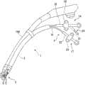
图1是表示本实施方式的缝合器1的图。缝合器1是由捆绑条(tape)等将其与内窥镜装置100束在一起、插入患者等的体腔内使用的器具。FIG. 1 is a diagram showing a
缝合器1包括:插入体内的插入部2;设在插入部2前端的前端部3,其用于进行缝合;设在插入部2的基端侧的操作部4,其用于操作前端部3。The
图2是表示安装并收容在缝合器1中的缝合单元103的图。缝合单元103包括缝合线104、缝合线104贯穿其中的止挡件105、安装在缝合线104的两端的呈棒状的第1固定器106和第2固定器107。各固定器106、107上,在外表面的一部分上分别沿整周设有卡合槽106A、107A。FIG. 2 is a diagram showing the
止挡件105通过使由金属或者生物可降解树脂等的树脂等材料构成的板状构件的左、右端部105A和105B相对地折弯,并使端部105A与105B彼此卡合而形成。The
止挡件105的左右方向中央附近设有孔105C,在中点104A处被折弯后的缝合线104配置为从与端部105A、105B相反一侧的面贯穿孔105C,并从彼此卡合的端部105A和端部105B之间穿过。关于止挡件105在使用时的动作将在后面说明。A hole 105C is provided near the center of the
插入部2为具有可挠性的管状构件,在其内部贯穿有用于操作前端部3的操作线和用于射出缝合单元103的固定器106、107的推压件等。The
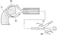
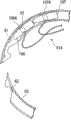
图3是用局部断面表示前端部3的放大图。前端部3包括用于把持处置对象部位的组织(以下称为“对象组织”。)的一对钳口10、用于刺入对象组织并射出固定器106、107的针管11、以及支承缝合单元103的止挡件105的止挡件支承部12。FIG. 3 is an enlarged view showing the
钳口10由图3中的上侧的第1钳口10A和下侧的第2钳口10B构成,通过使第1钳口10A和第2钳口10B的彼此相对的面(把持面)以接近的方式闭合来把持对象组织。用于操作钳口10开、合的未图示的操作线穿过插入部2连接于操作部4。The
针管11是前端锋利地形成的空心构件。如图3所示,针管11的前端侧勾画一条曲线而朝插入部2的前端侧折返,形成为钩状,并且针管11以穿过第1钳口10A的把持面的方式与第1钳口10A固定为一体。因此,针管11与钳口10的开合操作联动而以第1钳口10A的基端为中心旋转地移动。The
为了进行上述那样的移动,优选针管11的从插入部2伸出的起始部11A具有一定的柔软性。通过由镍钛合金等超弹性金属形成针管11整体,或者由树脂形成比起始部11A靠基端侧的区域,能够确保这样的柔软性。In order to perform the movement as described above, it is preferable that the starting
针管11的内腔中收容有缝合单元的各固定器106、107。各固定器的卡合槽106A、107A分别与朝针管11的内腔侧突出设置的未图示的卡合突起相卡合,从而防止各固定器106、107的误射出和自然脱落等。
缝合单元103的缝合线104自形成于针管11的钩状的内周侧的槽11B被引出到针管11的外面。用于射出固定器106、107的推压件13贯穿至固定器106、107的基端侧。推压件13穿过插入部2延伸至操作部4。The
由于各固定器106、107如图3所示地收容在弯曲的针管11的内腔中,因此优选形成为直径朝长度方向的两端逐渐收缩的锥状,这样该两端不易卡在针管11的内壁上。此外,优选各固定器106、107用上述超弹性金属或者生物可降解塑料等形成为具有可挠性,这样在针管11内的移动及射出可顺畅地进行。同样,推压件13由于也在弯曲的内腔中进退而形成为具有可挠性。Since each
止挡件支承部12包括贯穿插入部的外鞘14和贯穿外鞘14的卡止构件15。外鞘14是具有可挠性的管状构件,它能够相对于插入部2在轴线方向进、退。卡止构件15在前端具有钩15A,该卡止构件15延伸至操作部4。The
如图3所示,从针管11的槽11B引出的缝合线104被引入到外鞘14内。并且,缝合线104的被折弯的中点104A被卡止构件15的钩15A卡止,止挡件105抵接在外鞘14的前端而被支承。As shown in FIG. 3 , the
回到图1中,操作部4包括用于操作钳口10及推压件13的第1操作部16和用于操作止挡件支承部12的第2操作部17。Referring back to FIG. 1 , the operation part 4 includes a
第1操作部16包括主体18、在主体18的轴线方向可滑动地安装在主体18上的滑决19、以及一端安装在主体18上的推压件操作部20。滑块19上连接有与钳口10连接的操作线的端部,通过使滑块19相对于主体18滑动,能够进行钳口10的开合操作。The
推压件操作部20是筒状构件,其与主体18成一定的角度而向主体18的基端侧延伸。推压件操作部20内可进退地贯穿有穿过插入部2和主体18内部的推压件13的基端侧,在伸出的推压件13的端部上安装有捏手21。使用者利用捏手21使推压件13朝着推压件操作部20前进,从而能够使固定器106、107从针管11射出。The
第2操作部17包括主体22和在主体22的轴线方向可滑动地安装在主体22上的滑块23。主体22上连接有贯穿插入部2的外鞘14的基端,通过使主体22相对于插入部2进、退,能够改变外鞘14的从插入部2的前端伸出的长度。滑块23上连接有贯穿外鞘14的卡止构件15的基端,通过使滑块23相对于主体22滑动,能够改变外鞘14与卡止构件15的长度方向上的位置关系。The
关于上述那样构成的缝合器1在使用时的动作进行说明。The operation of the
首先,使用者将缝合器1插入患者等的体腔内,使前端部3移动到有穿孔或者裂伤等处置对象部位的胃壁等的附近。此时,首先将内窥镜装置100插入体腔内,使内窥镜装置100的基端贯穿公知的套管(未图示),以内窥镜装置100作为引导件将套管插入体腔内后暂且将内窥镜装置100拔出。然后,如图1所示将内窥镜装置100和缝合器1用捆绑条或者捆绑带等捆成一体后插入套管并插入体腔内,从而能够将形状复杂的前端部3顺畅地导入到对象组织附近。First, the user inserts the
使用者操作第1操作部16的滑块19将钳口10打开,使其接近处置对象部位的一方的对象组织T1,然后使钳口10闭合。于是,如图3所示,对象组织T1由钳口10把持,同时,针管11的穿过第1钳口10A的把持面的锋利的前端刺入对象组织T1。使用者进一步使钳口10闭合,则针管11的前端从分为二叉的第2钳口10B之间穿过并贯通对象组织T1。The user operates the
接着使用者操作推压件操作部20使推压件13前进,于是,如图4所示,推压件将固定器106、107向针管的前端侧推出,首先前端侧的第1固定器106被从针管11射出。使用者根据针管11内部的卡合突起越过第1固定器106的卡合槽106A的时候产生的感觉(咔嗒的感觉)能够认识到第1固定器106已被射出。Then, the user operates the push
使用者按照同样的顺序,如图5所示,在处置对象部位的另一方的对象组织T2处将第2固定器107射出,并使其卡止于该对象组织T2。从对象组织T2拔出针管11后,使用者在保持第2操作部17的主体22与滑块23的位置关系的同时将该主体22推入插入部2。于是,如图6所示,止挡件支承部12的外鞘14从插入部2伸出。Following the same procedure, the user injects the
外鞘14从插入部2伸出,则卡止在卡止构件15的钩15A上的缝合单元103的缝合线104被向外鞘14内收容,止挡件105与外鞘14的前端面保持相抵接的状态下,仅缝合线104被向外鞘14内收容,止挡件105与各固定器106、107的距离变短。When the
由于各固定器106、107分别卡止在组织T1及T2上,所以,如图6所示,随着止挡件105与各固定器106、107靠近,对象组织T1、T2与各固定器106、107一起被拉向缝合器1一侧而紧贴。如此,进行处置对象部位T的缝合。Since each
此时,虽然缝合线104向中点104A侧移动而被向外鞘14内收容时止挡件105的端部105A与端部105B的卡合变得松弛,但是即使缝合线104欲向各固定器106、107侧移动,但由于端部105A和端部105B会因作用在缝合线104上的力而更加牢固地卡合,因此缝合线104不能朝该方向移动。即,由于止挡件105仅朝各固定器106、107侧移动而不朝其相反侧移动,所以不会发生处置对象部位T的缝合变松或者被解除的情况。At this time, although the engagement between the
缝合结束后,使用者使外鞘14后退。然后,操作滑块23使卡止构件15相对于外鞘14前进而从外鞘14伸出。然后,在通过内窥镜装置100进行的观察下解除钩15A与缝合线104的卡合,使缝合单元103脱离缝合器1。如此,一系列的处置即告结束。After the suturing is completed, the user retracts the
根据本实施方式的缝合器1,射出各固定器106、107的针管11以穿过可开合的一对钳口10的一方的第1钳口10A的把持面的方式弯曲形成。因此,在将针管11刺入对象组织T1、T2等时,能够用内窥镜装置100进行观察,由于针管11贯通了组织之后针管11的前端也朝向插入部2一侧,所以能够用内窥镜装置100进行观察。According to the
在现有的缝合器中,由于针管为直线状,所以用内窥镜装置不易辨认刺入组织时候的针管的前端位置,就可靠地进行固定器的射出这一点而言,针管前端的辨认性不能令人满意。在本实施方式的缝合器1中,能够用内窥镜装置100确认针管11的前端露出到对象组织T1等的外面,并且能够一边用内窥镜装置100进行观察,一边进行各固定器106、107的射出。因此,能够使缝合单元103更加可靠地卡止在处置对象组织上而进行精确的缝合。In the existing stapler, since the needle tube is linear, it is difficult to recognize the position of the tip of the needle tube when piercing the tissue with an endoscope device. Unsatisfactory. In the
接下来,关于本发明的第2实施方式,参照图7至图15进行说明。本实施方式的缝合器31与上面说明的缝合器1的不同之处在于,针管穿过延伸设置到钳口的通道而被导入。Next, a second embodiment of the present invention will be described with reference to FIGS. 7 to 15 . The difference between the
另外,在以后的说明中,关于与已经说明过的实施方式中的构成要素共同的部分,分别赋予同一个符号而省略重复的说明。In addition, in the following description, the same code|symbol is attached|subjected to the part common to the component in the embodiment already demonstrated, and the overlapping description is abbreviate|omitted.
图7是表示缝合器31的构成的整体图。缝合器31包括具有一对钳口的把持机构32和贯穿把持机构32的缝合机构33。FIG. 7 is an overall view showing the configuration of the
把持机构32的基本结构记载在美国专利公开公报2006/0271073中,以下对其概要进行说明。The basic structure of the holding mechanism 32 is described in US Patent Publication No. 2006/0271073, and the outline thereof will be described below.
把持机构32包括与插入部2大体上相同的插入部34、安装在插入部34的前端的一对钳口35和用于操作钳口35进行开、合的手柄36。The holding mechanism 32 includes an
上侧的第1钳口35A比下侧的第2钳口35B短,第1钳口35A的基端旋转自如地支承在第2钳口35B的长度方向中间附近。第2钳口35B的基端旋转自如地支承在插入部34的前端附近。The upper
第1钳口35A上连接有具有可挠性的钳口开合外鞘37。钳口开合外鞘37可进退地贯穿在设于插入部34的通道中,其基端与手柄36连接。因此,使用者通过操作手柄36使钳口开合外鞘37相对于插入部34进、退,能够使第1钳口35A旋转从而进行钳口35的开、合。A flexible jaw opening and closing
在第1钳口35A的与第2钳口35B相对的把持面上设有通孔38(图10参照),钳口开合外鞘37的前端贯穿通孔38而被固定,因此,钳口开合外鞘37的内腔延伸到第1钳口35A的把持面。第2钳口35B上与通孔38相对应的位置上设有通孔或者狭缝等结构,在进行后面将要说明的操作时,缝合机构33的针管能够穿过第2钳口35B的把持面。A through hole 38 (refer to FIG. 10 ) is provided on the holding surface opposite to the
缝合机构33的构成大概与第1实施方式的缝合器1相同,因此以不同点为中心进行说明。The configuration of the
图8A、图8B分别是以局部断面表示缝合机构33的前端侧、缝合机构33的操作部41的放大图。如图8A所示,针管39形成为直线状。针管39可进退地贯穿外鞘40,缝合单元103的止挡件105也收容在外鞘40的内腔中。缝合线104的中点104A从形成在针管39上的通孔39A插入针管39的内腔,卷挂在推压件13上。8A and 8B are enlarged views showing the front end side of the
如图8B所示,外鞘40的基端连接在操作部41的主体18上,针管39的基端连接在滑块19上。推压件操作部20安装在滑块19上,其与滑块19一起相对于主体18滑动。As shown in FIG. 8B , the base end of the
根据上述构成,使用者通过使滑块19相对于主体18进、退而使针管39相对于外鞘40进行相对移动,从而能够使针管39的前端出没于外鞘40。此时,由于推压件操作部20与滑块19成一体滑动,所以针管39与推压件13的位置关系不变。According to the above configuration, the user can move the tip of the
如图7所示,缝合机构33从设在把持机构32的手柄36上的未图示的插入口可进退地插入在钳口开合外鞘37中。因此,使用者通过将主体18朝手柄36侧推挤,能够使外鞘40从第1钳口35A的把持面伸出。As shown in FIG. 7 , the
关于上述那样地构成的缝合器31在使用时的动作进行说明。The operation of the
首先,使用者将缝合器31与内窥镜装置100束在一起,将钳口35导入到处置对象部位的附近。将缝合器31插入通道中的时机,既可以在将内窥镜装置100插入体腔内之前,也可以在其之后。First, the user bundles the
接下来,使用者操作手柄36,如图9所示那样用钳口35夹住一方的对象组织T 1而将其把持。然后,使缝合机构33的主体18相对于插入部34前进,使外鞘40的前端移动到第1钳口35A附近,同时,使滑块19相对于主体18前进,如图10所示那样用针管39贯穿对象组织T1,由于推压件13的操作,如图11所示那样将第1固定器106从针管39射出并使其卡止在对象组织T1上。Next, the user operates the handle 36, and grasps one target tissue T1 with the
此时,由于针管39的前端朝向内窥镜装置100的前端侧,所以使用者利用内窥镜装置100能够容易地观察针管39的前端的位置和固定器射出的情景。第1固定器106射出后,使用者使针管39后退,解除对对象组织T1的把持。At this time, since the distal end of the
使用者按照同样的顺序,如图12所示那样使第2固定器107卡止在对象组织T2上。然后,如图13所示,将止挡件105送出到外鞘40的外部后,使主体18相对于钳口开合外鞘37前进,如图14所示,用外鞘40推挤止挡件105,从而使其向各固定器106、107例移动。如此,进行处置对象部位的紧束缝合。Following the same procedure, the user locks the
使用者操作推压件操作部20使推压件13相对于针管39充分后退,则缝合线104与推压件13的卡合脱开,如图15所示,缝合单元103脱离缝合器31。When the user operates the
在将把持机构32和现有的、使用缝合线的一端安装有固定器且没有止挡件的缝合单元的缝合机构组合起来进行缝合的场合,使用者需要在用把持机构32同时夹住并把持对象组织T1、T2的状态下将针管刺入。同时把持2个组织并非一件容易之事,该手艺的难易程度是不低的。When the holding mechanism 32 is combined with the existing sewing mechanism of the suturing unit with a fixer installed at one end of the suture thread and there is no stopper for suturing, the user needs to use the holding mechanism 32 to clamp and hold the suture at the same time. The needle tube is inserted in the state of the target tissues T1 and T2. It is not an easy task to control two organizations at the same time, and the difficulty of this skill is not low.
根据本发明的缝合器,由于使用具有2个固定器106、107及止挡件105的缝合单元103,所以仅分别把持对象组织T1、T2并将固定器卡止,即可一边确实地对针管39的前端进行观察一边进行处置对象组织的缝合。因此,能够更加容易且准确地实施缝合手艺。According to the suturing device of the present invention, since the
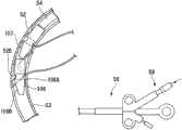
接下来,关于本发明的第3实施方式,参照图16至图41C进行说明。本实施方式的缝合器51与上面说明的各实施方式的缝合器的不同之处在于包括2根针管。Next, a third embodiment of the present invention will be described with reference to FIGS. 16 to 41C. The
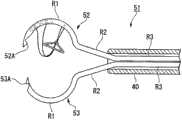
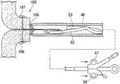
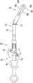
图16是表示缝合器51的前端部的图。外鞘40中贯穿有2根针管——第1针管52和第2针管53。各针管52、53包括:前端侧的、弯曲成大致圆弧状的第1区域R 1;与第1区域R1的基端相连接、随着逐渐接近前端而向离开外鞘40的轴线的方向延伸的第2区域R2;与第2区域R2的基端侧相连接并与后述的操作部相连接的第3区域R3。FIG. 16 is a diagram showing the front end portion of the
各针管52、53虽然整体由超弹性金属形成,但是刺入组织的第1区域R1由比第2区域R2的弹性率低的硬质超弹性金属形成,第2区域R2由比第1区域R 1的弹性率高的超弹性金属形成。然后,通过熔接等方法把由弹性率不同的超弹性金属形成的第1区域R1和第2区域R2制成一体,由此形成各针管52、53。第3区域R3由与第2区域R2相同的超弹性金属形成,并且通过在各区域R2、R3的分界部折弯而形成。另外,取代该方法,也可以由弹性率更高、具有可挠性的超弹性金属或者具有可挠性的树脂等形成第3区域R3,再将其与第2区域R2接合。采用树脂的场合,适合使用例如聚醚醚酮(PEEK)等。Although each
如图16所示,各针管52、53的第1区域R1以朝外鞘40的径向外侧突出的方式彼此相对地形成。此外各针管52、53的前端分别设有卡合突起52A和53A,卡合突起52A和53A能够以彼此可分离的方式卡合,通过使二者卡合,能够使各针管52、53的第1区域成为大致的环状。此外,用于解除卡合突起52A与53A的卡合的解除突起52B自卡合突起52A附近的内周面突出。解除突起52B的基端侧的斜面的角度形成为各固定器106、107的前端侧106B、107B的圆锥角以下大小的角度。各固定器106、107的基端侧106C、107C的圆锥角小于前端侧106B、107B的圆锥角,从而基端侧106C、107C的外径的收缩程度小于前端侧。As shown in FIG. 16 , the first regions R1 of the
各针管52、53内分别贯穿有与推压件13相同的第1推压件54及第2推压件55,它们朝操作部56延伸。A
图18是表示缝合器51的操作部56的图,图19是操作部56的剖视图。在主体18上,与第1针管52的基端相连接的第1滑块57和与第2针管53的基端相连接的第2滑块58这2个滑块分别可独立滑动地安装在主体18上。各滑块57、58上分别安装有第1推压件操作部59和第2推压件操作部60,第1推压件54及第2推压件55的基端侧分别贯穿在第1推压件操作部59及第2推压件操作部60中。FIG. 18 is a diagram showing the
关于上述那样地构成的缝合器51在使用时的动作,参照图20至图30进行说明。The operation of the
首先,使用者使各滑块57、58后退,如图20所示,将各针管52、53及止挡件105以收容在外鞘40内的状态插入内窥镜装置100的通道。然后,将内窥镜装置100插入患者等的体内,使内窥镜100的前端移动到处置对象部位附近。First, the user moves the
接下来,使用者使各滑块57、58前进,使各针管52、53及止挡件105从外鞘40伸出。于是,各针管52、53的第1区域R1及第2区域R2由于超弹性金属的弹性而恢复到图21所示的收容前的形状。Next, the user advances the
使用者将对象组织T1夹在第1针管52和第2针管53之间后使各滑块57、58后退。于是,各针管52、53向对象组织T 1刺入,如图22所示,在对象组织T1的内部卡合突起52A与53A相卡合,第1针管52及第2针管53形成大致的环状。After the user sandwiches the target tissue T1 between the
接着,为了进行固定器的射出,使用者使针管52、53的卡合部位向对象组织T1的外部移动。此时,使用者可以如图23所示,操作内窥镜装置100使环状的针管52、53旋转,也可以如图24所示,一边使一方的滑块(例如第1滑块57)前进,一边使另一方的滑块(例如第2滑块58)后退从而使针管52、53的卡合部位移动。Next, in order to inject the anchor, the user moves the engaged portion of the
在上述卡合部位移动到对象组织T1的外部之后,使用者如图25所示操作第1推压件操作部59使第1推压件54前进。被第1推压件54推挤的第1固定器106和第2固定器107在第1针管52内向前端侧移动而接近解除突起52B。After the engaging portion moves outside the target tissue T1, the user operates the first
由于解除突起52B的基端侧的斜面的角度在第1固定器106的前端侧106B的圆锥角以下,所以前端侧106B几乎不与解除突起52B接触,第1固定器106顺畅地向第2针管53侧移动。Since the angle of the inclined surface on the base end side of the
当槽106A向比解除突起52B靠第2针管53侧移动时,外径较大的基端侧106C与解除突起52B相接触。其结果,如图26所示,被基端侧106C推挤的解除突起52B以离开第2针管53的方式移动,由此,卡合突起52A与53A的卡合被解除,同时,如图27所示,第1固定器106被射出。此时,在第1固定器106留在第2针管53内的情况下,使第2推压件55前进,将第1固定器106射出即可。When the
使用者如图28所示将第1针管52从对象组织T1拔出之后,使缝合器51整体绕轴线翻转,按照同样的顺序如图29所示将第2固定器107卡止在对象组织T2上。然后,如图30所示,将各针管52、53拉入到外鞘40内,使止挡件105向各固定器106、107侧移动,对处置对象部位进行缝合。最后使第1推压件54充分后退,则缝合单元103与缝合器51脱离,手艺即告结束。After the user pulls out the
本实施方式的缝合器51中也由于固定器106、107从呈圆弧状弯曲的第1针管52的前端射出,所以能够一边在内窥镜装置100的视野中对针管的前端及固定器进行适宜的确认,一边进行精确的手艺。Also in the
本实施方式的缝合器51通过改变针管的内部形状,能够更加容易地将固定器卡止。以下关于该变形例进行说明。The
图31是缝合器51的变形例的缝合器51A中针管52、53的前端附近的放大剖视图。各针管52、53的前端附近的内表面上,分别沿周向设有用于进行固定器的交接的接受突起61、62。各接受突起61、62可与各固定器106、107的槽106A、107A卡合。各接受突起61、62的长度可根据以何种程度的强度保持固定器而适宜地确定。此外,在操作部56中,如图32所示,第1滑块57与第2滑块58是一体的。FIG. 31 is an enlarged cross-sectional view of the vicinity of the distal ends of the
关于上述那样地构成的缝合器51A在使用时的动作进行说明。The operation of the
与缝合器51同样,将针管52、53刺入对象组织T1,使滑块前进,使针管52、53在对象组织T1内卡合成环状。之后,使第1推压件54前进,如图32所示,使第1固定器106的槽106A与第2针管53的接受突起62卡合,第1固定器106被从第1针管52移交给第2针管53。Similar to the
使用者进一步推入第1推压件54,则如图33所示,第1固定器的基端侧106C冲上解除突起52B,针管52、53之间的卡合被解除。同时,第2固定器107的槽107A与第1针管52的接受突起61卡合。When the user further pushes in the
使用者使滑块57、58后退,则第1针管52及第2针管53如图34所示,分别以第2固定器107及第1固定器106收容在前端附近的状态被从对象组织T1中拔出。由此,从第1针管52侧刺入对象组织T1的第1固定器106穿过对象组织T1内,向第2针管53侧移动。然后,使用者使第2推压件55前进,将第1固定器106从第2针管53推出,则如图35所示,第1固定器106的射出完成。When the user moves the
使用者使缝合器51A绕轴线翻转,按照同样的顺序将第2固定器107移交给第2针管53,使该第2固定器107卡止在对象组织T2上。The user turns the
在缝合器51A中,由于在对象组织T1等的内部将收容在第1针管52中的第1固定器106移交给第2针管53,所以能够不使第1针管52贯通对象组织T1等,仅使固定器贯通对象组织T1等而向第2针管53侧移动并卡止。因此能够以更加简便的操作进行缝合。In the
另外,在上面说明的缝合器51A中,虽然对在第1针管52与第2针管53卡合的状态下进行固定器的交接的例子进行了说明,但是在确保各针管的前端相向的状态良好的情况下,可以不必使二者卡合就能进行固定器的移交。In addition, in the
此外,在缝合器51A中,没有必要像缝合器51那样使针管52、53的卡合部位露出到对象组织T1等的外边,所以如图32及图35所示,将第1滑块57与第2滑块58一体构成也是可以的。这样的话操作就变得更加简单,但是对于缝合器51A而言该结构并非必须,与缝合器51同样,各滑块57、58分别采用可滑动的结构也是可以的。In addition, in the
并且,在上面说明的缝合器51及51A中,各针管52、53的构造不被上述结构限制。例如,像图36及图37所示的变形例那样,各针管52、53也可以通过将多个针构件63可旋转地连接而构成。Furthermore, in the above-described
在这种情况下,如图37所示,在各针管52、53的最前端侧的针构件63A上固定用于将针构件63保持为各针管52、53的形状的张紧线64的一端。并且,一边使张紧线64的通过设于各针构件63的弯曲的外周侧的内表面上的引导件65,一边使其另一方的端部延伸到各推压件操作部59、60,并安装用于操作的把手66(参照图39)。In this case, as shown in FIG. 37 , one end of a
在使用该缝合器的时候,使各滑块57、58前进而如图38所示那样使针构件63从外鞘40伸出之后,操作把手66将连接在各针管52、53上的张紧线64向基端侧牵引,于是,如图39所示,各针构件63被保持为针管52、53的弯曲形状,成为可刺入对象组织T1等的状态。When using this stapler, after each
采用这样的构成,在牵引张紧线64时针管52、53的第1区域R1变成实质上的硬质,在松开张紧线64时第1区域R1变成实质上的软质。其结果,能够以更小的力容易地进行针管52、53相对于外鞘40内的出、入,并且在刺入组织的时候,能够赋予针管52、53充分的刚性进行更加可靠的穿刺。With such a configuration, the first region R1 of the
图40是表示缝合器51的其他变形例中的针管的图,图41A、图41B及图41C分别是沿图的A-A线、B-B线及C-C线的剖视图。如图41A所示,刺入组织时等时受到较大力的针管67的第1区域R1的前端侧仅由不锈钢等金属等构成的硬质构件68形成。第1区域R1的需要一定的弹性的剩余部分和第2区域R2的前端侧,如图41B所示,其一部分例如仅弯曲形状的外周侧由硬质构件68形成,剩余部分由具有弹性的树脂等的柔软构件69形成。并且,第2区域R2的基端侧及第3区域R3仅用柔软构件69形成。这样,针管67构成为随着接近基端侧硬质构件68的比例逐渐降低。其结果,作为材料,即使不用超弹性金属,也能构成既具有所期望的弹性而可被收容在外鞘40内,又能在从外鞘40伸出时恢复到所期望的弯曲形状的针管67。通过使用被加工成图40所示形状的硬质构件68并借助嵌入成形等方法,能够良好地制造出这样的针管67。另外,在上面的说明中的硬质材料的比例的变化位置仅为一例,可以根据针管67所要求的刚性及弹性进行适宜的变更。40 is a diagram showing a needle tube in another modified example of the
接下来,关于本发明的第4实施方式,参照图42至图48进行说明。本实施方式为包括内窥镜装置、缝合机构和内窥镜用钳子的缝合系统。本实施方式的缝合系统71中,作为内窥镜装置及缝合机构,虽然可以适宜地采用上面说明的内窥镜装置100及缝合机构33,但是并不局限于这些装置或者机构。Next, a fourth embodiment of the present invention will be described with reference to FIGS. 42 to 48 . This embodiment is a suturing system including an endoscope device, a suturing mechanism, and endoscope forceps. In the
图42是表示缝合系统71所用的内窥镜用钳子72的一例的图。内窥镜用钳子72包括被插入体腔内的插入部73、设在插入部73的前端的把持部74和设在插入部73的基端侧的操作部75。FIG. 42 is a diagram showing an example of
插入部73具有:具有可挠性的柔软部76;和可旋转地支承在柔软部76的前端的弯曲部77。弯曲部77的旋转面与把持部74的开合方向平行。操作线等传递构件连接在弯曲部77上,其穿过插入部73延伸到操作部75。The
把持部74具有一对钳口74A及74B。用于进行钳口74A、74B的开合操作的操作线等传递构件延伸到操作部75。在钳口74A及74B上,如图42及图43所示,分别设有沿钳口74A及74B的开合方向贯穿钳口74A及74B且彼此连通的通孔78A及78B,和分别与通孔78A及78B相连通且延伸至各钳口74A、74B的彼此相对的把持面的周缘的狭缝79A及79B。通孔78A、78B的内径设定为小于缝合机构33的外鞘40的外径,从而外鞘40不能进入。The
此外,钳口74A、74B中的至少一方上设有导向面80,该导向面80形成为与把持面相反一侧的通孔的开口周缘以随着逐渐接近该通孔而逐渐接近把持面的方式逐渐变深的斜面状。导向面80设在两方的钳口上也是可以的。In addition, at least one of the
操作部75包括与插入部73连接的主体81、用于操作把持部74的滑块82和用于操作弯曲部77的弯曲操作部83。滑块82上连接有从把持部74延伸出来的传递构件,通过使滑块82相对于主体81滑动,能够开、合把持部74。弯曲操作部83为棒状构件,其长度方向中心旋转自如地支承在主体81上。弯曲操作部83的长度方向两端上连接有从弯曲部77延伸出来的传递构件,通过使弯曲操作部83旋转,如图所示,能够使弯曲部77与柔软部76所成的角度发生改变,从而能够使把持部74的朝向发生改变。The
关于像上述那样地构成的缝合系统71在使用时的动作进行说明。在使用缝合系统71时,将缝合机构33及内窥镜用钳子72插入内窥镜装置100的通道里并使其如图44所示伸出。插入缝合机构33及内窥镜用钳子72的时机既可以在将内窥镜装置100插入体腔内之前,也可以在之后。The operation of the
使用者将内窥镜装置100导入到处置对象部位附近之后,如图45所示,用内窥镜用钳子72把持对象组织T1。此时,使导向面80朝向缝合机构33一侧。After the user introduces the
使用者一边把持着对象组织T1,一边操作弯曲操作部83,使把持部74朝向缝合机构33一侧。此时,优选将缝合机构33的针管39预先收容在外鞘40内,以免针管39被不经意地刺入对象组织T1。While holding the target tissue T1 , the user operates the bending
把持部74朝向缝合机构33一侧,导向面80即向缝合机构33的前方移动。使用者使外鞘40前进,则外鞘40的前端被向导向面80引导而接近通孔78B,外鞘40的内腔与通孔78B连通。使用者将外鞘40进一步向前方推入,则外鞘40的前端与把持部74一起以弯曲部77的基端为中心旋转,如图47所示,外鞘40的前端侧弯曲成与内窥镜装置100的轴线大致正交的状态。The gripping
在该状态下使用者使滑块19前进,则针管39如图48所示,穿过通孔78B而贯通对象组织T1,穿过通孔78A而伸出。如此能够将第一固定器106射出并使其卡止在对象组织T1上。固定器卡止后,解除把持部74的把持,则缝合单元103的缝合线104穿过狭缝79A、79B,脱离把持部74。In this state, the user moves the
根据本实施方式的缝合系统71,通过使用具有弯曲部77的内窥镜用钳子72把持对象组织,缝合机构33的外鞘40与把持部74一起旋转而弯曲成其前端侧与内窥镜装置100的轴线大致正交的状态。其结果,由于能够一边用内窥镜装置100确实地观察伸出的针管39的前端,一边进行固定器的射出,所以能够提高固定器射出的可靠性。According to the
此外,由于通孔处设有导向面80,所以即使通孔的位置略微离开缝合机构33的轴线,外鞘40的前端也会被良好地引入,从而将外鞘40的内腔与通孔连通。In addition, since the through hole is provided with a
进而,由于通孔的孔径设定的比外鞘40的外径小,所以防止了发生外鞘40进入通孔内并被卡住拔不出来的情况。因此,能够更加容易地实施手艺。Furthermore, since the aperture of the through hole is set smaller than the outer diameter of the
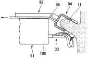
接下来,关于本发明的第5实施方式,参照图49至图54进行说明。本实施方式的缝合系统91与上面说明的第4实施方式的缝合系统71的不同之处在于:代替内窥镜用钳子而采用了吸引罩。Next, a fifth embodiment of the present invention will be described with reference to FIGS. 49 to 54 . The
图49是表示缝合系统91在使用时的前端的图。缝合系统91中,代替内窥镜用钳子72,采用了与内窥镜装置100束在一起插入体腔内的吸引罩92。Fig. 49 is a diagram showing the front end of the
吸引罩92包括插入体腔内的插入部93、安装在插入部93的前端的罩部94和与罩部94连接的吸引管95。The
插入部93具有弯曲部96,如图49所示,可将罩部94向缝合机构33侧弯曲操作。The
如图49及图50所示,罩部94为有底的圆筒状构件,在与上面说明的内窥镜用钳子72的把持部74相同的位置上设有通孔97A、97B及抽线用的狭缝98A、98B。与通孔78B相同地,在缝合机构33侧的通孔97B处形成有导向面99。As shown in FIGS. 49 and 50 , the
吸引管95的前端与罩部94的底面相连接并朝罩部94的内部开口,其基端与未图示的吸引机构相连接。并且,通过使该吸引机构工作,能够使罩部94的内部成为负压而将组织向罩部94内吸引。The distal end of the
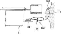
上述那样地构成的缝合系统91能够按照与缝合系统71大体上同样的顺序进行固定器的射出及卡止。即,如图51所示,在将对象组织T1吸引到罩部94内的状态下,操作弯曲部96使其向缝合机构33侧弯曲。然后,如图52所示,使外鞘40的前端抵接在导向面99上之后,如图53所示,用针管39贯通对象组织T1,射出第1固定器106,如图54所示,将第1固定器106卡止在对象组织T1上。The
在本实施方式的缝合系统91中,也与缝合系统71同样地,能够一边用内窥镜装置100观察贯通了对象组织T1后的针管39的前端,一边可靠地进行各固定器106、107的射出。In the
另外,虽然在上面说明的第4及第5实施方式中,对缝合机构插入内窥镜装置的通道的例子进行了说明,但是,也可以代替这种方式,使缝合机构以可在内窥镜装置的长度方向上相对移动的方式外置配置。In addition, in the fourth and fifth embodiments described above, the example in which the suturing mechanism is inserted into the channel of the endoscope device has been described, but instead of this mode, the suturing mechanism can be made to be endoscopic. The device is arranged externally in a relatively movable manner in the length direction.
接下来,关于本发明的6实施方式,参照图55至图58进行说明。本实施方式的缝合系统121与上面说明的各实施方式的缝合系统的不同之处在于,作为观察手段的内窥镜装置的前端构成为能够移动到可对贯通对象组织后的缝合机构的针管进行观察的位置。Next, six embodiments of the present invention will be described with reference to FIGS. 55 to 58 . The
图55是缝合系统121的整体图。缝合系统121包括内窥镜装置100和缝合机构33,缝合机构33不是插入内窥镜装置100的通道内,而是以彼此的插入部并行的方式与内窥镜装置100被捆束。FIG. 55 is an overall view of the
如图55所示,缝合机构33贯穿内窥镜保持架122,内窥镜装置100可进退地贯穿安装在内窥镜保持架122上的第1引导件123。并且,内窥镜装置100的插入部101与缝合机构33的外鞘40被辅助引导件124捆束。辅助引导件124的个数可以根据插入部101和外鞘40的长度等适宜地确定。此外,辅助引导件124可以固定在插入部101及外鞘40中的任意一方上。As shown in FIG. 55 , the
插入部101的前端侧安装有内窥镜固定带125,缝合机构33的前端侧且比内窥镜固定带125更靠前的前端侧安装有缝合机构固定带126。内窥镜固定带125与缝合机构固定带126用硬质的连杆127连接。连杆127的两端分别可旋转地轴支承在内窥镜固定带125及缝合机构固定带126上。连杆127的两端被轴支承为在同一平面上旋转。An
关于上述那样地构成的缝合系统121在使用时的动作进行说明。首先将缝合系统121导入体腔内,使针管39刺入对象组织T1。此时,如图56所示,在初始状态,即缝合机构固定带126位于比内窥镜固定带125更靠近前方(前端侧)的状态,由于内窥镜装置100的前端位于外鞘40的前端附近,所以能够对针管39的刺入情况进行良好的观察。The operation of the
在针管39处于对象组织T1内的状态下,使用者一边保持内窥镜保持架122,一边将内窥镜装置100向前方推入。于是,如图57所示,连杆127以缝合机构固定带126侧的端部为中心旋转,固定有内窥镜固定带125的处置内窥镜100的前端移动到比外鞘40的前端更靠近前方的位置。With the
在该状态下针管39贯通对象组织T1,则如图58所示,由于能够用处置内窥镜100对针管39的前端进行良好的观察,所以能够可靠地将第1固定器106等射出。In this state, the
在本实施方式的缝合系统121中,优选缝合机构33的外鞘40具有上面说明的处置内窥镜100的推动及旋转动作不易使其弯曲变形程度的刚性,因为这样的构成使内窥镜装置100的前端的移动得以顺畅地进行。除此之外,从保持被捆束起时的对于体腔内的良好的插入性的观点来看,作为内窥镜装置100,优选使用插入部101的直径在5毫米到8毫米程度,即所谓的细径内窥镜。In the
接下来,关于本发明的第7实施方式,参照图59至图64进行说明。本实施方式的缝合系统131与上述各实施方式的缝合系统的不同之处在于缝合机构的针管的伸出形态。Next, a seventh embodiment of the present invention will be described with reference to FIGS. 59 to 64 . The difference between the
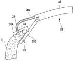
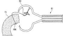
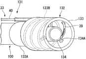
图59是表示缝合系统131的前端侧的立体图。缝合机构33的外鞘40的前端连接有用于向内窥镜装置100的前端进行安装的穿刺罩132。FIG. 59 is a perspective view showing the front end side of the
图60是穿刺罩132的沿轴线方向的剖视图。穿刺罩132包括外侧的筒体133和安装在筒体133的内部的吸引杯134。FIG. 60 is a cross-sectional view of the
筒体133为由树脂等制成的大致圆筒状的构件,通过使处置内窥镜100的前端嵌合在基端侧的嵌合部133A,能够将二者连接起来。此外,筒体133的壁面上呈螺线状地形成有供针管39贯穿用的针管通道133B。针管通道133B的前端在筒体133的内表面开口。The
本实施方式的针管39采用与上面说明的针管同样的超弹性金属形成,为了能顺畅地贯穿针管通道133B内,针管39被赋予了成螺线状环起来的特性。不过,使用时从针管通道133B的前端伸出的一定长度的区域被赋予了比该环的其他区域更强烈地弯曲的特性。The
吸引杯134借助支承部134A支承在筒体133的内壁上。吸引杯134的基端134B通过插入内窥镜装置100的通道,能够与该通道气密性地连接。因此,将吸引杯134与通道连接,通过将通道和未图示的吸引装置连接起来,能够用吸引杯134对组织进行吸引。The
为了用内窥镜装置对用吸引杯134吸引的组织进行良好的观察,优选筒体133及吸引杯134由具有透明性的树脂等形成。例如,可以适宜地采用高透明度的多氯联苯(PCB)等。In order to observe well the tissue sucked by the
关于上述那样地构成的缝合系统131在使用时的动作进行说明。首先,使用者将吸引杯134的基端134B与内窥镜装置100的通道连接从而将筒体133安装在内窥镜装置100的前端,然后将缝合系统131插入体腔内,使前端移动到对象组织T1的附近。The operation of the
接下来,使用者推动筒体133使其碰到对象组织T1,使吸引装置工作,如图61所示,用吸引杯134将对象组织T1的一部分吸引到筒体133的内部。然后,操作滑块19使针管39前进。Next, the user pushes the
针管39在筒体133的针管通道133B内前进,并从针管通道133B的前端的开口伸出到筒体133的内部。如上所述,针管39的前端侧被赋予了比其他区域更强烈地弯曲的特性,所以如图62所示,它朝着穿刺罩132的轴线伸出。即,针管39朝着容易刺入被吸引杯134吸引的对象组织T1的一部分的方向伸出。The
因此,使用者进一步使针管39前进,则如图63所示,针管39刺入并贯通对象组织T1。由于针管39在筒体133的内部刺入并贯通对象组织T1,所以使用者能够用内窥镜装置100确实地看到针管39的前端的一系列的举动。Therefore, when the user further advances the
之后,如图64所示,按照与上面说明的各实施方式大体上同样的顺序将第1固定器106从针管39射出。将针管36从对象组织T1拔出并使吸引杯134停止吸引,则第1固定器106向对象组织T1的卡止完成。Thereafter, as shown in FIG. 64 , the
在本实施方式的缝合系统131中,使用者用吸引杯134吸引对象组织T1,仅利用滑块19操作针管39就能够可靠地进行固定器的射出。因此,无需像上面说明的缝合系统91、121等那样把持对象组织、使其向缝合机构33一侧弯曲这样2个阶段的操作,能够更加简便且更加准确地进行包括固定器的射出在内的缝合作业。In the
虽然在上述实施方式中,对用吸引杯134吸引并保持对象组织T 1的例子进行了说明,但是也可以通过其他手段进行对象组织的保持。例如,可以用筒体133直接对组织进行吸引,也可以从内窥镜装置100的通道伸出钳子等装置把持对象组织。Although in the above-mentioned embodiment, the example in which the target tissue T1 is sucked and held by the
接下来,关于本发明的第8实施方式,参照图65至图68进行说明。本实施方式的缝合系统141与上面说明的各实施方式的缝合系统的不同之处在于缝合机构与内窥镜装置的连接形态。Next, an eighth embodiment of the present invention will be described with reference to FIGS. 65 to 68 . The difference between the
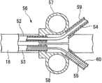
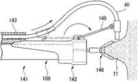
图65是表示缝合系统141的构成的整体图。缝合机构33贯穿罩外鞘143,该罩外鞘143的前端安装有提升罩142。提升罩142包括前端侧的筒体142A和基端侧的套筒142B。FIG. 65 is an overall view showing the configuration of the
筒体142A与穿刺罩132同样地,能够通过使内窥镜装置100的前端与其嵌合而固定在内窥镜装置100上。套筒142B用软性材料形成,它支承着罩外鞘143的前端,使该罩外鞘143的前端不与内窥镜装置100分离。The
从罩外鞘143伸出的外鞘40的前端上安装有连杆固定部144。连杆固定部144由与缝合系统121的连杆127大体上同样的硬质连杆145与筒体142A的外周面连结。连杆145能够相对于连杆固定部144及筒体142A进行移动。A
关于上述那样地构成的缝合系统141在使用时的动作进行说明。首先,使用者将提升罩142安装在内窥镜装置100的前端,从罩外鞘143的基端插入缝合机构33。缝合机构33的插入也可以在将内窥镜装置100及罩外鞘143插入体腔内之后进行。The operation of the
接下来,如图66所示,使用者利用贯穿在内窥镜装置100中的内窥镜用的钳子146把持对象组织T1。由于钳子146没有像内窥镜用钳子72所包括的那样的弯曲部77,所以其只是直线前进而把持对象组织T1。Next, as shown in FIG. 66 , the user grasps the target tissue T1 with
在钳子146把持着对象组织T1的状态下,使用者一边保持罩外鞘143,一边将缝合机构33向前端侧推入,使缝合机构33相对于罩外鞘143前进。若进一步使缝合机构33前进,则连杆145以提升罩142侧的端部为中心旋转,如图67所示,外鞘40的前端向内窥镜装置100的前方移动,且前端的开口与被钳子146把持的对象组织T1相对。在该状态下使用者操作滑块19,如图68所示,用针管39贯通对象组织T1,射出第1固定器106。With the
根据本实施方式的缝合系统141,若使缝合机构33前进,则在连杆145的作用下,外鞘40的前端向内窥镜装置100的前方移动,能够使针管39与内窥镜装置100的轴线大致正交那样地伸出。因此,能够一边用内窥镜装置100确实地观察贯通对象组织T1后的针管39的前端,一边进行固定器的射出。According to the
接下来,关于本发明的第9实施方式,参照图69至图72进行说明。本实施方式的缝合系统151与上面说明的各实施方式的缝合系统的不同之处在于,除了内窥镜装置还包括第2观察装置。Next, a ninth embodiment of the present invention will be described with reference to FIGS. 69 to 72 . The
图69是表示缝合系统151的前端的图。钳子146和缝合机构33贯穿在内窥镜装置100的通道中。在安装于内窥镜装置的前端的罩152上可进退地贯穿有轴构件154,该轴构件154在其前端安装有第2观察手段——镜子153。镜子153上安装有未图示的操作线等操作构件,通过操作该操作构件,能够调节镜子153与轴构件154所成的角度。FIG. 69 is a diagram showing the front end of the
在上述那样地构成的缝合系统151中,如图70所示,通过使贯通对象组织T1的针管39的前端映照在镜子153中,能够用内窥镜装置100进行观察。因此,能够一边辨认针管39的前端,一边将固定器可靠地射出。此时,可以适宜地调节镜子153与轴构件154所成的角度以获得良好的视野。In the
此外,第2观察手段不限于镜子153,例如图71所示的细径内窥镜155也是可以的。在这种情况下,如图72所示,通过用细径内窥镜155观察贯通了对象组织T1的针管39的前端,能够更加可靠地进行固定器的射出。In addition, the second observation means is not limited to the
接下来,关于本发明的第10实施方式,参照图73至图78进行说明。本实施方式的缝合器161与上面说明的各实施方式的缝合器或者缝合系统的不同之处在于,在针管从外鞘伸出的状态下,能够变形为后述的穿刺形态。Next, a tenth embodiment of the present invention will be described with reference to FIGS. 73 to 78 . The difference between the
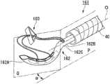
图73是表示缝合器161的前端的图。针管162中,收容有缝合单元103的前端部162A大致圆弧状地形成,其还在与大致呈直线状的基端侧部分162B的交界162C处倾斜地形成为与基端侧部分162B成角度α。FIG. 73 is a diagram showing the front end of the
如图73所示,角度α是包含弯曲的前端部162A的平面Q与包含基端侧部分162B的中心轴线O的平面P所成的角,通常被设定为大于0度并以90度为上限。针管162在从外鞘40伸出的状态下自然变形为如图73所示的适宜于刺入组织的形状(以下称为“穿刺形态”。)。As shown in FIG. 73 , the angle α is an angle formed by a plane Q including the curved
此外,针管162收容在外鞘40内时,如图74所示,其保持有以不使具有大致直线状的基本形状的外鞘40变形的程度变形成大致直线状,且收容有针管162的外鞘40能够插入内窥镜装置100的通道的程度的可挠性。为了使针管162具有这样的特性,在本实施方式中,针管162的前端部162A用超弹性合金形成。In addition, when the
此外,如后面将要说明的那样,为了使针管162在穿刺对象组织等的时候,使针管162整体绕基端侧部分162B的中心轴线旋转,基端侧部分162B用具有足以传递操作部所输入的旋转扭矩的扭转刚性的材料形成。In addition, as will be described later, in order to make the
作为具体的例子,有基端侧部分162B也使用超弹性合金管的方法、作为基端侧部分162B使用由密绕线圈形成的管状构件的方法等方法。密绕线圈若采用将多条单线以排列状态进行卷绕的多条绕线,或者同轴地配置多个线圈的多层绕线等技巧,则不仅能提高扭转刚性,而且十分有效。Specific examples include a method of using a superelastic alloy tube for the
在使针管162穿刺组织的时候,使用者对操作部(未图示)进行操作,如图75所示,使针管162绕基端侧部分162B的中心轴线旋转,使针尖抵接在对象组织T 1上。之后,如图76所示,通过使针管162旋转,用通常的外科手术中以持针器保持弯曲针进行缝合时的要领,针对对象组织T1进行刺入、刺出。通过将角度α设定在大于0度、小于等于90度的范围内,仅以针管162绕轴线的旋转操作,即可进行向对象组织的刺入、刺出。此外,由于针管162的前端部162A相对于基端侧部分162A的中心轴线O倾斜,所以能够在利用内窥镜装置100进行的观察下进行针管162的刺入及刺出。因此,与上面说明的各实施方式的缝合器及缝合系统同样,能够进行精确的缝合。When puncturing the tissue with the
图77是表示本实施方式的变形例的缝合器161A的图。图示中省略了所收容的缝合单元103。针管165由前端部165A、基端侧部分165B及前端部165A与基端侧部分165B之间的中间部165C构成,各区域分别由第1旋转销166及第2旋转销167旋转自如地连结。中间部165C能够以第1旋转销166为中心旋转,其与基端侧部分165B所成的角度在上述α的范围内。同样,前端部165A能够以第2旋转销167为中心旋转,其基端侧的轴线与中间部165C所成的角度在β的范围内。角度β的上限也可与α同样,设定为90度。FIG. 77 is a diagram showing a
针管165的内腔中与图36至图39所示的变形例同样,贯穿有张紧线64,另外还贯穿有推压件13。张紧线64的前端固定在前端部165A的内壁上。张紧线64与上面说明的第3实施方式的变形例同样,贯穿设在中间部165C的内壁上的引导件65并延伸到手边侧的未图示的操作部,固定在未图示的把手上。比引导件65更靠近前端侧的张紧线64能够从设在前端部165A的弯曲外侧的面上的未图示的缺口露出。Like the modified examples shown in FIGS. 36 to 39 , the inner cavity of the
将具有如上述那样构成的针管165的缝合器或者缝合机构插入内窥镜装置的通道的时候,在张紧线64上没有牵引力作用的状态下将针管165收容在外鞘40内。从内窥镜装置的前端使外鞘40伸出之后,使针管165从外鞘40伸出,牵引把手,则在张紧线64的牵动下,前端部165A绕第2旋转销167旋转,并在成角度β处抵在中间部165C的端面上而得以保持。同样,中间部165C绕第1旋转销166旋转并在成角度α之处抵在基端侧部分165B的端面上而得以保持。这样,针管165根据使用者的操作变形成穿刺形态。When a stapler or a suturing mechanism having the
在上面说明的变形例中,借助把手牵引张紧线64,从而能够将针管165保持为实质上的硬质的穿刺形态,能够以更强的力进行缝合。In the modified example described above, the
在述的变形例中,也可以如图78A所示,在针管165的前端部165A形成大致平行地形成的槽168,使其两端向内卷直到彼此接触。这样,针管的前端变得尖锐,且能够使外径变小,因此能够以较轻的气力容易地进行向对象组织等的穿刺。In the modification described above, as shown in FIG. 78A , grooves 168 formed substantially in parallel may be formed in the
如上面说明的那样,由于针管165由可弹性变形的材料形成,所以在射出固定器的时候,随着固定器的通过,如图78B所示,槽168的前端侧瞬间被扩宽,从而固定器106等的放出成为可能。固定器通过后,针管165由于弹性而恢复到固定器射出前的形状。As explained above, since the
以上,关于第1实施方式到第10实施方式进行了说明,但是本发明的诸多实施方式中共同的重要要素,是针管的材料兼具适度的弹性和刚性。在赋予针管以这样的弹性和刚性的情况中,除了上面所说明的那样的超弹性合金之外,还可以适宜地采用例如聚酰胺、聚醚醚酮(PEEK)、聚砜、液晶聚合物(LCP)等树脂材料,或者氧化铝、氮化硅等具有生物适应性的陶瓷材料等。As above, the first to tenth embodiments have been described, but the important element common to many embodiments of the present invention is that the material of the needle tube has both appropriate elasticity and rigidity. In the case of imparting such elasticity and rigidity to the needle tube, in addition to the above-described superelastic alloys, for example, polyamide, polyether ether ketone (PEEK), polysulfone, liquid crystal polymer ( LCP) and other resin materials, or biocompatible ceramic materials such as alumina and silicon nitride.
以上,对本发明的优选实施例做了说明,但是本发明并不局限于这些实施例。在不超出本发明的宗旨的范围内,可以进行构成的附加、省略、置换及其他变更。The preferred embodiments of the present invention have been described above, but the present invention is not limited to these embodiments. Additions, omissions, substitutions, and other changes can be made without departing from the gist of the present invention.
例如,在上面说明的各实施方式中,对使用了在缝合线的端部安装有第1固定器及第2固定器2个固定器的缝合单元的例子进行了说明,但是也可以取代这种缝合单元而使用在缝合线的一方的端部上仅安装有1个固定器的缝合单元。For example, in each embodiment described above, the example of using the suturing unit in which the first anchor and the second anchor are attached to the end of the suture thread has been described, but this may be substituted. Instead of the suture unit, a suture unit with only one anchor attached to one end of the suture thread was used.
在这种情况,将夹着处置对象部位相对的2个部位的对象组织同时贯通并使固定器卡止,将没有固定器的缝合线的端部向外拉出,之后,在该端部安装固定器。然后,顺着缝合线将固定器导入到处置对象部位,用2个固定器进行缝合即可。In this case, the target tissues of the two opposing parts of the treatment target part are penetrated at the same time, the anchor is locked, the end of the suture without the anchor is pulled out, and then the suture is attached to the end. Holder. Then, guide the anchor along the suture line to the part to be treated, and suture with two anchors.
本发明并不由前述的说明限定,其仅由所附的权利要求书的范围限定。The present invention is not limited by the foregoing description, but is only limited by the scope of the appended claims.
工业实用性Industrial Applicability
根据本发明,在针管刺入对象组织等时,以及针管贯穿组织之后,均能够用内窥镜装置对针管进行观察。能够用内窥镜装置确认针管的前端露出对象组织等的外面的情况,并且能够一边用内窥镜装置进行观察,一边进行各固定器的射出。因此,能够使缝合单元更加可靠地卡止在处置对象组织上而进行精确的缝合。According to the present invention, the needle tube can be observed with the endoscope device both when the needle tube penetrates into the target tissue and after the needle tube penetrates the tissue. It is possible to confirm with the endoscope device that the tip of the needle tube is exposed to the outside of the target tissue or the like, and it is possible to perform injection of each fixator while observing with the endoscope device. Therefore, the suturing unit can be locked more reliably on the tissue to be treated to perform precise suturing.
附图标记的说明Explanation of reference signs
1、31、51、51A、161 缝合器1, 31, 51, 51A, 161 Stapler
10、35、74 钳口10, 35, 74 Jaws
11、39、67、162、165 针管11, 39, 67, 162, 165 needle tube
13 推压件13 push parts
32 把持机构32 control mechanism
33 缝合机构33 Suture Mechanism
52 第1针管52 1st needle tube
53 第2针管53 2nd Needle Tube
54 第1推压件54 The first push piece
55 第2推压件55 2nd push piece
71、91、121、131、141、151 缝合系统71, 91, 121, 131, 141, 151 suture system
77、96 弯曲部77, 96 bending part
78A、78B、97A、97B 通孔78A, 78B, 97A, 97B Through-hole
80、99 导向面80, 99 guide surface
92 吸引罩92 suction cover
100 内窥镜装置100 endoscopic devices
103 缝合单元103 Suture unit
132 穿刺罩132 piercing cover
133 筒体133 barrel
133B 针管通道133B needle channel
142 提升罩142 Lift Hood
143 罩外鞘143 Cover sheath
145 连杆145 connecting rod
152 罩152 cover
155 细径内窥镜155 narrow diameter endoscope
Claims (16)
Translated fromChineseApplications Claiming Priority (3)
| Application Number | Priority Date | Filing Date | Title |
|---|---|---|---|
| US12/265,790 | 2008-11-06 | ||
| US12/265,790US20100113873A1 (en) | 2008-11-06 | 2008-11-06 | Suturing device and suturing system |
| PCT/JP2009/068896WO2010053118A1 (en) | 2008-11-06 | 2009-11-05 | Suture device and suture system |
Publications (1)
| Publication Number | Publication Date |
|---|---|
| CN102164548Atrue CN102164548A (en) | 2011-08-24 |
Family
ID=42132259
Family Applications (1)
| Application Number | Title | Priority Date | Filing Date |
|---|---|---|---|
| CN2009801385437APendingCN102164548A (en) | 2008-11-06 | 2009-11-05 | Suture device and suture system |
Country Status (5)
| Country | Link |
|---|---|
| US (1) | US20100113873A1 (en) |
| EP (1) | EP2316346B1 (en) |
| JP (1) | JP4624485B2 (en) |
| CN (1) | CN102164548A (en) |
| WO (1) | WO2010053118A1 (en) |
Cited By (23)
| Publication number | Priority date | Publication date | Assignee | Title |
|---|---|---|---|---|
| CN104955405A (en)* | 2012-09-02 | 2015-09-30 | 塞特里克斯有限公司 | Suturing device |
| CN105163678A (en)* | 2013-06-11 | 2015-12-16 | 奥林巴斯株式会社 | Treatment tool for endoscope |
| CN106214197A (en)* | 2016-07-14 | 2016-12-14 | 张强 | Scope aciculiform stiching instrument |
| CN106983533A (en)* | 2017-05-10 | 2017-07-28 | 陈永兵 | The puncture needle and first-aid system of the live hemostasis of abdominal cavity substantial viscera rupture |
| CN107582117A (en)* | 2017-10-10 | 2018-01-16 | 史惠忠 | A kind of stitching unstrument and its method of work |
| CN107693134A (en)* | 2017-10-18 | 2018-02-16 | 璁稿嘲 | Double needle hole neurosurgery fixing device |
| CN108601589A (en)* | 2016-02-05 | 2018-09-28 | 杜拉塔有限责任公司 | The device and method placed for suture |
| CN110099611A (en)* | 2017-01-31 | 2019-08-06 | 日本瑞翁株式会社 | Stitching devices |
| CN110301950A (en)* | 2019-07-19 | 2019-10-08 | 刘奇为 | Automatic suturing mechanism and its application method for Minimally Invasive Surgery |
| US10624631B1 (en) | 2017-11-13 | 2020-04-21 | Simon B. Rayhanabad | Surgical suture and method of suturing |
| CN111466972A (en)* | 2020-04-28 | 2020-07-31 | 张强 | Suture implantation device and suture |
| US10792036B2 (en) | 2017-11-15 | 2020-10-06 | Winter Innovations, Llc | Method and apparatus for double loop stitching |
| CN112040881A (en)* | 2018-05-01 | 2020-12-04 | 兄弟工业株式会社 | Suturing device |
| CN112512397A (en)* | 2018-07-31 | 2021-03-16 | 奥林巴斯株式会社 | Endoscope system and curved needle delivery method |
| CN112568954A (en)* | 2020-12-31 | 2021-03-30 | 河南科技大学第一附属医院 | Wound department skin fixing device |
| US11213290B2 (en) | 2017-11-15 | 2022-01-04 | Winter Innovations, Inc. | Methods and systems for double loop stitching |
| WO2022027231A1 (en)* | 2020-08-04 | 2022-02-10 | 丁海雁 | Heart valve wire placement device |
| CN114642464A (en)* | 2022-03-15 | 2022-06-21 | 青岛智兴医疗器械有限公司 | Saddle-bottom dura mater stitching instrument and using method thereof |
| CN115211916A (en)* | 2021-04-21 | 2022-10-21 | 杭州德晋医疗科技有限公司 | Threaded suture device |
| CN116370150A (en)* | 2021-12-31 | 2023-07-04 | 杭州德晋医疗科技有限公司 | Easy-to-clamp transcatheter artificial chord implantation device and system |
| WO2023124638A1 (en)* | 2021-12-31 | 2023-07-06 | 杭州德晋医疗科技有限公司 | Implantation device with clamping and guiding functions |
| CN119302693A (en)* | 2024-10-25 | 2025-01-14 | 中国人民解放军总医院第一医学中心 | Surgical instrument for treating digestive tract fistula |
| CN120241153A (en)* | 2025-06-04 | 2025-07-04 | 浙江省肿瘤医院 | Suturing device for endoscopic treatment of postoperative perforation in the duodenum |
Families Citing this family (60)
| Publication number | Priority date | Publication date | Assignee | Title |
|---|---|---|---|---|
| ATE514382T1 (en) | 2006-11-30 | 2011-07-15 | Wilson Cook Medical Inc | FABRIC ANCHOR FOR SEAM CLOSURE OF PERFORATIONS |
| JP5226792B2 (en)* | 2007-09-25 | 2013-07-03 | クック メディカル テクノロジーズ エルエルシー | Medical instruments, devices and methods for using tissue anchors |
| WO2009082596A1 (en)* | 2007-12-18 | 2009-07-02 | Wilson-Cook Medical, Inc. | Device and method for placement of tissue anchors |
| AU2009204417B2 (en)* | 2008-01-03 | 2013-05-09 | Cook Medical Technologies Llc | Medical systems and devices for endoscopically suturing perforations |
| US8863748B2 (en)* | 2008-07-31 | 2014-10-21 | Olympus Medical Systems Corp. | Endoscopic surgical operation method |
| WO2010022060A1 (en) | 2008-08-19 | 2010-02-25 | Wilson-Cook Medical Inc. | Apparatus for removing lymph nodes or anchoring into tissue during a translumenal procedure |
| US8192461B2 (en) | 2008-09-11 | 2012-06-05 | Cook Medical Technologies Llc | Methods for facilitating closure of a bodily opening using one or more tacking devices |
| WO2010048420A1 (en)* | 2008-10-22 | 2010-04-29 | Cayenne Medical, Inc. | Arthroscopic suture passing devices and methods |
| US8377095B2 (en)* | 2008-12-05 | 2013-02-19 | Cook Medical Technologies, LLC | Tissue anchors for purse-string closure of perforations |
| AU2009324819B2 (en) | 2008-12-09 | 2014-04-17 | Cook Medical Technologies Llc | Retractable tacking device |
| EP2389122B1 (en) | 2008-12-19 | 2015-03-04 | Cook Medical Technologies LLC | Clip devices |
| EP2413809B1 (en)* | 2009-04-03 | 2014-10-08 | Cook Medical Technologies LLC | Medical devices for rapid deployment and fixation of tissue anchors |
| CA2757554A1 (en) | 2009-04-03 | 2010-10-07 | Cook Medical Technologies Llc | Tissue anchors and medical devices for rapid deployment of tissue anchors |
| EP2429374B1 (en)* | 2009-05-01 | 2013-09-25 | Cook Medical Technologies LLC | Medical device for suturing perforations |
| JP2012527970A (en) | 2009-05-28 | 2012-11-12 | クック メディカル テクノロジーズ エルエルシー | Hail-fastening device and hail-fastening device deployment method |
| US20110178537A1 (en)* | 2010-01-20 | 2011-07-21 | Whitman Michael P | Tissue repair implant and delivery device and method |
| US10058314B2 (en) | 2010-01-20 | 2018-08-28 | Micro Interventional Devices, Inc. | Tissue closure device and method |
| US10743854B2 (en) | 2010-01-20 | 2020-08-18 | Micro Interventional Devices, Inc. | Tissue closure device and method |
| US10959840B2 (en) | 2010-01-20 | 2021-03-30 | Micro Interventional Devices, Inc. | Systems and methods for affixing a prosthesis to tissue |
| US9980708B2 (en) | 2010-01-20 | 2018-05-29 | Micro Interventional Devices, Inc. | Tissue closure device and method |
| EP2624779B1 (en) | 2010-10-08 | 2018-05-30 | Koninklijke Philips N.V. | Endoscopy-guided deployment of vessel punch |
| US20120108901A1 (en)* | 2010-11-03 | 2012-05-03 | Tyco Healthcare Group Lp | Mirrored arthroscope |
| ES2701781T3 (en)* | 2010-12-23 | 2019-02-25 | Surgimatix Inc | Cutaneous suture device that uses rotating needles |
| CN103209648B (en)* | 2011-06-02 | 2016-04-06 | 奥林巴斯株式会社 | Suture thread pressing device and suture thread pressing system |
| WO2013008817A1 (en)* | 2011-07-11 | 2013-01-17 | オリンパスメディカルシステムズ株式会社 | Treatment system and endoscopic system |
| US9192375B2 (en) | 2012-02-29 | 2015-11-24 | Marker Medical, Llc | Surgical apparatus and method |
| KR20140133918A (en) | 2012-03-13 | 2014-11-20 | 스미스 앤드 네퓨, 인크. | Surgical needle |
| US9301842B2 (en)* | 2013-01-31 | 2016-04-05 | St. Jude Medical, Inc. | Method and device for heart valve repair |
| WO2014123207A1 (en) | 2013-02-05 | 2014-08-14 | Olympus Corporation | Medical manipulator |
| EP2967645A1 (en) | 2013-03-15 | 2016-01-20 | Smith & Nephew, Inc. | Surgical needle |
| FR3008885B1 (en)* | 2013-07-26 | 2016-12-30 | Landanger | SURGICAL DEVICE, IN PARTICULAR FOR THE INSTALLATION OF MITRAL CORRING PROSTHESIS |
| GB2523159A (en)* | 2014-02-14 | 2015-08-19 | Neosurgical Ltd | Surgical device |
| US20170071591A1 (en)* | 2014-02-28 | 2017-03-16 | Saturix Ltd. | Devices and methods for closing openings in body tissue |
| US20150272558A1 (en)* | 2014-03-25 | 2015-10-01 | Boston Scientific Scimed, Inc. | Devices, methods and kits for tissue approximation |
| WO2016061044A1 (en) | 2014-10-15 | 2016-04-21 | Smith & Nephew, Inc. | Anchor/ implant deployment device and tissue repair methods relate thereto |
| WO2016061046A1 (en)* | 2014-10-15 | 2016-04-21 | Smith & Nephew, Inc. | Arthroscopic meniscal tear repair device |
| US9775710B2 (en) | 2015-01-27 | 2017-10-03 | Landanger | Surgical device |
| US10499904B2 (en) | 2015-02-17 | 2019-12-10 | Smith & Nephew, Inc. | Anchor insertion system and method of use thereof |
| US20160361051A1 (en)* | 2015-06-09 | 2016-12-15 | Boston Scientific Scimed, Inc. | System for the parallel delivery of an element into the esophageal mucosa |
| CN206390950U (en) | 2015-07-07 | 2017-08-11 | 莫尔研究应用有限公司 | Equipment for two organizing segments to be stitched together |
| EP3331452A4 (en)* | 2015-08-07 | 2019-08-28 | Mayo Foundation for Medical Education and Research | ENDOLUMINAL ANASTOMOSIS AND TISSUE CLOSURE DEVICES |
| US10342540B2 (en) | 2015-10-15 | 2019-07-09 | Boston Scientific Scimed, Inc. | Tissue retraction devices and related methods of use |
| USD785793S1 (en) | 2016-06-14 | 2017-05-02 | Landanger | Device for mitral prosthesis rope laying |
| WO2018087769A1 (en) | 2016-11-13 | 2018-05-17 | Anchora Medical Ltd. | Minimally-invasive tissue suturing device |
| US10925597B2 (en)* | 2016-12-29 | 2021-02-23 | Medtentia International Ltd Oy | Medical securing device for securing an object with a securing member |
| US11364025B2 (en)* | 2017-01-24 | 2022-06-21 | Elad Rash | Suture passer |
| EP3417832A1 (en)* | 2017-06-22 | 2018-12-26 | Medtentia International Ltd Oy | Medical securing device for securing an object with a securing member |
| WO2019036541A2 (en)* | 2017-08-17 | 2019-02-21 | Boston Scientific Scimed, Inc. | Anchor delivery system and methods for valve repair |
| US12213662B2 (en) | 2017-11-14 | 2025-02-04 | Intuitive Surgical Operations, Inc. | Electrically weldable suture material, and apparatus and method for forming welded suture loops and other welded structures |
| EP3709931B1 (en)* | 2017-11-14 | 2024-10-16 | Egan Design LLC | Electrically weldable suture material |
| CN109984778B (en)* | 2017-12-29 | 2022-02-22 | 先健科技(深圳)有限公司 | Medical suturing device and suturing system |
| US20210401428A1 (en)* | 2018-10-30 | 2021-12-30 | Health Research, Inc. | Devices and methods for automatic suture |
| JP7357083B2 (en)* | 2019-06-28 | 2023-10-05 | ボストン サイエンティフィック サイムド,インコーポレイテッド | Manual internal guidewire navigation for annuloplasty |
| CN114711859B (en)* | 2022-03-04 | 2025-03-25 | 上海市嘉定区安亭医院 | Suturing device for digestive endoscopic surgery |
| JP2023149923A (en)* | 2022-03-31 | 2023-10-16 | 日本ゼオン株式会社 | Endoscope treatment instrument |
| US20240225633A1 (en)* | 2023-01-06 | 2024-07-11 | Durastat Llc | Suturing device |
| CN116509477B (en)* | 2023-03-20 | 2025-08-08 | 浙江大学滨江研究院 | Take-up device for oval hole suture head |
| WO2024253670A1 (en)* | 2023-06-03 | 2024-12-12 | De La Cruz Munoz Nestor | Endoscopic tissue inversion and resection system and method of resecting tissue |
| US12303115B2 (en) | 2023-06-03 | 2025-05-20 | University Of Miami | Endoscopic tissue inversion and resection system and method of resecting tissue |
| WO2025038589A2 (en)* | 2023-08-14 | 2025-02-20 | Intuitive Surgical Operations, Inc. | Endoscopic suturing system utilizing a linear drive needle |
Citations (6)
| Publication number | Priority date | Publication date | Assignee | Title |
|---|---|---|---|---|
| US20050119671A1 (en)* | 2003-11-13 | 2005-06-02 | Usgi Medical Inc. | Apparatus and methods for endoscopic suturing |
| US20060271073A1 (en)* | 2005-05-26 | 2006-11-30 | Usgi Medical Inc. | Methods and apparatus for securing and deploying tissue anchors |
| WO2007037326A1 (en)* | 2005-09-28 | 2007-04-05 | Olympus Medical Systems Corp. | Suturing device |
| CN101043843A (en)* | 2004-06-30 | 2007-09-26 | 詹姆士·V·西茨曼 | Medical devices for minimally invasive surgery and other internal procedures |
| US20070293720A1 (en)* | 2005-01-05 | 2007-12-20 | Avantis Medical Systems, Inc. | Endoscope assembly and method of viewing an area inside a cavity |
| CN101137330A (en)* | 2005-03-17 | 2008-03-05 | 奥林巴斯株式会社 | Suture instrument |
Family Cites Families (14)
| Publication number | Priority date | Publication date | Assignee | Title |
|---|---|---|---|---|
| US5540704A (en)* | 1992-09-04 | 1996-07-30 | Laurus Medical Corporation | Endoscopic suture system |
| CA2133377C (en)* | 1993-10-08 | 2004-09-14 | H. Jonathan Tovey | Surgical suturing apparatus with loading mechanism |
| JP3406090B2 (en)* | 1994-10-19 | 2003-05-12 | オリンパス光学工業株式会社 | Endoscope device |
| US6821285B2 (en)* | 1999-06-22 | 2004-11-23 | Ndo Surgical, Inc. | Tissue reconfiguration |
| US6544271B1 (en)* | 2000-07-18 | 2003-04-08 | Scimed Life Systems, Inc. | Device for full-thickness resectioning of an organ |
| US6736773B2 (en)* | 2001-01-25 | 2004-05-18 | Scimed Life Systems, Inc. | Endoscopic vision system |
| JP4373146B2 (en)* | 2002-07-11 | 2009-11-25 | オリンパス株式会社 | Endoscopic suturing device |
| JP4533695B2 (en)* | 2003-09-23 | 2010-09-01 | オリンパス株式会社 | Treatment endoscope |
| US7029435B2 (en)* | 2003-10-16 | 2006-04-18 | Granit Medical Innovation, Llc | Endoscope having multiple working segments |
| WO2006033671A2 (en)* | 2004-04-15 | 2006-03-30 | Wilson-Cook Medical Inc. | Endoscopic surgical access devices and methods of articulating an external accessory channel |
| US8444657B2 (en)* | 2004-05-07 | 2013-05-21 | Usgi Medical, Inc. | Apparatus and methods for rapid deployment of tissue anchors |
| US8057511B2 (en)* | 2004-05-07 | 2011-11-15 | Usgi Medical, Inc. | Apparatus and methods for positioning and securing anchors |
| US20060020167A1 (en)* | 2004-06-30 | 2006-01-26 | James Sitzmann | Medical devices for minimally invasive surgeries and other internal procedures |
| US20070203395A1 (en)* | 2006-02-28 | 2007-08-30 | Takayasu Mikkaichi | Cap installable on distal end portion of endoscope |
- 2008
- 2008-11-06USUS12/265,790patent/US20100113873A1/ennot_activeAbandoned
- 2009
- 2009-11-05EPEP09824817.2Apatent/EP2316346B1/ennot_activeNot-in-force
- 2009-11-05JPJP2010517217Apatent/JP4624485B2/ennot_activeExpired - Fee Related
- 2009-11-05CNCN2009801385437Apatent/CN102164548A/enactivePending
- 2009-11-05WOPCT/JP2009/068896patent/WO2010053118A1/enactiveApplication Filing
Patent Citations (6)
| Publication number | Priority date | Publication date | Assignee | Title |
|---|---|---|---|---|
| US20050119671A1 (en)* | 2003-11-13 | 2005-06-02 | Usgi Medical Inc. | Apparatus and methods for endoscopic suturing |
| CN101043843A (en)* | 2004-06-30 | 2007-09-26 | 詹姆士·V·西茨曼 | Medical devices for minimally invasive surgery and other internal procedures |
| US20070293720A1 (en)* | 2005-01-05 | 2007-12-20 | Avantis Medical Systems, Inc. | Endoscope assembly and method of viewing an area inside a cavity |
| CN101137330A (en)* | 2005-03-17 | 2008-03-05 | 奥林巴斯株式会社 | Suture instrument |
| US20060271073A1 (en)* | 2005-05-26 | 2006-11-30 | Usgi Medical Inc. | Methods and apparatus for securing and deploying tissue anchors |
| WO2007037326A1 (en)* | 2005-09-28 | 2007-04-05 | Olympus Medical Systems Corp. | Suturing device |
Cited By (35)
| Publication number | Priority date | Publication date | Assignee | Title |
|---|---|---|---|---|
| CN104955405A (en)* | 2012-09-02 | 2015-09-30 | 塞特里克斯有限公司 | Suturing device |
| CN105163678A (en)* | 2013-06-11 | 2015-12-16 | 奥林巴斯株式会社 | Treatment tool for endoscope |
| CN108601589A (en)* | 2016-02-05 | 2018-09-28 | 杜拉塔有限责任公司 | The device and method placed for suture |
| CN106214197A (en)* | 2016-07-14 | 2016-12-14 | 张强 | Scope aciculiform stiching instrument |
| CN110099611A (en)* | 2017-01-31 | 2019-08-06 | 日本瑞翁株式会社 | Stitching devices |
| CN110099611B (en)* | 2017-01-31 | 2022-03-11 | 日本瑞翁株式会社 | suture device |
| CN106983533A (en)* | 2017-05-10 | 2017-07-28 | 陈永兵 | The puncture needle and first-aid system of the live hemostasis of abdominal cavity substantial viscera rupture |
| CN107582117A (en)* | 2017-10-10 | 2018-01-16 | 史惠忠 | A kind of stitching unstrument and its method of work |
| CN107693134A (en)* | 2017-10-18 | 2018-02-16 | 璁稿嘲 | Double needle hole neurosurgery fixing device |
| CN107693134B (en)* | 2017-10-18 | 2020-03-27 | 许峰 | Double-pinhole neurosurgery fixing device |
| US10624631B1 (en) | 2017-11-13 | 2020-04-21 | Simon B. Rayhanabad | Surgical suture and method of suturing |
| US10792036B2 (en) | 2017-11-15 | 2020-10-06 | Winter Innovations, Llc | Method and apparatus for double loop stitching |
| US11213290B2 (en) | 2017-11-15 | 2022-01-04 | Winter Innovations, Inc. | Methods and systems for double loop stitching |
| US12070207B2 (en) | 2018-05-01 | 2024-08-27 | Brother Kogyo Kabushiki Kaisha | Suturing device |
| CN112040881A (en)* | 2018-05-01 | 2020-12-04 | 兄弟工业株式会社 | Suturing device |
| CN112040881B (en)* | 2018-05-01 | 2024-05-14 | 兄弟工业株式会社 | Suture device |
| CN112512397A (en)* | 2018-07-31 | 2021-03-16 | 奥林巴斯株式会社 | Endoscope system and curved needle delivery method |
| US12053174B2 (en) | 2018-07-31 | 2024-08-06 | Olympus Corporation | Endoscope system, curved needle delivery system, and curved needle delivery method |
| CN112512397B (en)* | 2018-07-31 | 2024-07-26 | 奥林巴斯株式会社 | Endoscope system |
| CN110301950A (en)* | 2019-07-19 | 2019-10-08 | 刘奇为 | Automatic suturing mechanism and its application method for Minimally Invasive Surgery |
| CN110301950B (en)* | 2019-07-19 | 2024-03-15 | 刘奇为 | Automatic suturing mechanism for minimally invasive surgery and endoscope |
| CN111466972A (en)* | 2020-04-28 | 2020-07-31 | 张强 | Suture implantation device and suture |
| CN114052989B (en)* | 2020-08-04 | 2024-08-27 | 启维医疗技术(深圳)有限责任公司 | Heart valve wire-placing device |
| WO2022027231A1 (en)* | 2020-08-04 | 2022-02-10 | 丁海雁 | Heart valve wire placement device |
| CN114052989A (en)* | 2020-08-04 | 2022-02-18 | 丁海雁 | Heart valve thread placing device |
| CN112568954B (en)* | 2020-12-31 | 2023-02-07 | 河南科技大学第一附属医院 | Wound skin fixation device |
| CN112568954A (en)* | 2020-12-31 | 2021-03-30 | 河南科技大学第一附属医院 | Wound department skin fixing device |
| CN115211916A (en)* | 2021-04-21 | 2022-10-21 | 杭州德晋医疗科技有限公司 | Threaded suture device |
| WO2023124638A1 (en)* | 2021-12-31 | 2023-07-06 | 杭州德晋医疗科技有限公司 | Implantation device with clamping and guiding functions |
| CN116370150A (en)* | 2021-12-31 | 2023-07-04 | 杭州德晋医疗科技有限公司 | Easy-to-clamp transcatheter artificial chord implantation device and system |
| CN114642464A (en)* | 2022-03-15 | 2022-06-21 | 青岛智兴医疗器械有限公司 | Saddle-bottom dura mater stitching instrument and using method thereof |
| CN114642464B (en)* | 2022-03-15 | 2022-11-08 | 青岛智兴医疗器械有限公司 | Supinal dura mater stitching instrument and using method thereof |
| CN119302693A (en)* | 2024-10-25 | 2025-01-14 | 中国人民解放军总医院第一医学中心 | Surgical instrument for treating digestive tract fistula |
| CN119302693B (en)* | 2024-10-25 | 2025-05-27 | 中国人民解放军总医院第一医学中心 | Surgical instrument for treating digestive tract fistula |
| CN120241153A (en)* | 2025-06-04 | 2025-07-04 | 浙江省肿瘤医院 | Suturing device for endoscopic treatment of postoperative perforation in the duodenum |
Also Published As
| Publication number | Publication date |
|---|---|
| JPWO2010053118A1 (en) | 2012-04-05 |
| EP2316346A1 (en) | 2011-05-04 |
| JP4624485B2 (en) | 2011-02-02 |
| EP2316346B1 (en) | 2017-12-27 |
| US20100113873A1 (en) | 2010-05-06 |
| EP2316346A4 (en) | 2012-01-04 |
| WO2010053118A1 (en) | 2010-05-14 |
Similar Documents
| Publication | Publication Date | Title |
|---|---|---|
| CN102164548A (en) | Suture device and suture system | |
| US8353920B2 (en) | Suture instrument | |
| US20250160819A1 (en) | Endoscopic suturing system having external instrument channel | |
| JP3880907B2 (en) | Endoscopic suture device | |
| JP4584230B2 (en) | Clip device | |
| AU2003257977B2 (en) | Placing sutures | |
| EP2613712B1 (en) | Apparatus for passing suture through tissue | |
| US8142448B2 (en) | Endoscopic instruments for suturing tissues in a body cavity | |
| JP5393317B2 (en) | Suture device | |
| US20100198235A1 (en) | Surgical suture passer and method for passing suture | |
| EP1938761A1 (en) | Suturing device | |
| US20110118757A1 (en) | Surgical end effector apparatus and method | |
| US20040127915A1 (en) | Suture hoop system | |
| US20030004544A1 (en) | Endoscopic instruments | |
| JP5371610B2 (en) | Suture device | |
| US20150257751A1 (en) | Suturing device | |
| JP2003225241A (en) | Therapeutic manipulator for endoscope | |
| WO2019140166A1 (en) | Device and method for securing endoscope relative to suturing system | |
| WO2022193951A1 (en) | Positioner, conveyor, tunnel-type wire passing system, and operating method therefor | |
| JP2012024607A (en) | Suture device | |
| CN112512397A (en) | Endoscope system and curved needle delivery method | |
| JP4838946B2 (en) | Suture tool | |
| US20230200806A1 (en) | Traction tool, traction system, and traction method and suturing method for suture thread |
Legal Events
| Date | Code | Title | Description |
|---|---|---|---|
| C06 | Publication | ||
| PB01 | Publication | ||
| C10 | Entry into substantive examination | ||
| SE01 | Entry into force of request for substantive examination | ||
| C02 | Deemed withdrawal of patent application after publication (patent law 2001) | ||
| WD01 | Invention patent application deemed withdrawn after publication | Application publication date:20110824 |