CN102164263B - Device and method of audio/video signal transmission interface - Google Patents
Device and method of audio/video signal transmission interfaceDownload PDFInfo
- Publication number
- CN102164263B CN102164263BCN201110059165ACN201110059165ACN102164263BCN 102164263 BCN102164263 BCN 102164263BCN 201110059165 ACN201110059165 ACN 201110059165ACN 201110059165 ACN201110059165 ACN 201110059165ACN 102164263 BCN102164263 BCN 102164263B
- Authority
- CN
- China
- Prior art keywords
- interface
- audio
- resistor
- line
- video signal
- Prior art date
- Legal status (The legal status is an assumption and is not a legal conclusion. Google has not performed a legal analysis and makes no representation as to the accuracy of the status listed.)
- Active
Links
- 230000008054signal transmissionEffects0.000titleclaimsabstractdescription63
- 238000000034methodMethods0.000titleclaimsdescription25
- 238000001514detection methodMethods0.000claimsabstractdescription42
- 230000005540biological transmissionEffects0.000claimsabstractdescription22
- 238000003780insertionMethods0.000claimsdescription20
- 230000037431insertionEffects0.000claimsdescription20
- 238000010586diagramMethods0.000description31
- 230000001276controlling effectEffects0.000description7
- 230000005236sound signalEffects0.000description7
- 230000000875corresponding effectEffects0.000description2
- 238000003672processing methodMethods0.000description2
- 230000011664signalingEffects0.000description2
- 238000004458analytical methodMethods0.000description1
- 238000005516engineering processMethods0.000description1
- 230000004048modificationEffects0.000description1
- 238000012986modificationMethods0.000description1
- 230000003287optical effectEffects0.000description1
- 230000001960triggered effectEffects0.000description1
Images


Classifications
- H—ELECTRICITY
- H04—ELECTRIC COMMUNICATION TECHNIQUE
- H04R—LOUDSPEAKERS, MICROPHONES, GRAMOPHONE PICK-UPS OR LIKE ACOUSTIC ELECTROMECHANICAL TRANSDUCERS; DEAF-AID SETS; PUBLIC ADDRESS SYSTEMS
- H04R5/00—Stereophonic arrangements
- H04R5/04—Circuit arrangements, e.g. for selective connection of amplifier inputs/outputs to loudspeakers, for loudspeaker detection, or for adaptation of settings to personal preferences or hearing impairments
- H—ELECTRICITY
- H04—ELECTRIC COMMUNICATION TECHNIQUE
- H04N—PICTORIAL COMMUNICATION, e.g. TELEVISION
- H04N21/00—Selective content distribution, e.g. interactive television or video on demand [VOD]
- H04N21/40—Client devices specifically adapted for the reception of or interaction with content, e.g. set-top-box [STB]; Operations thereof
- H04N21/43—Processing of content or additional data, e.g. demultiplexing additional data from a digital video stream; Elementary client operations, e.g. monitoring of home network or synchronising decoder's clock; Client middleware
- H04N21/436—Interfacing a local distribution network, e.g. communicating with another STB or one or more peripheral devices inside the home
- H04N21/4363—Adapting the video stream to a specific local network, e.g. a Bluetooth® network
- H04N21/43632—Adapting the video stream to a specific local network, e.g. a Bluetooth® network involving a wired protocol, e.g. IEEE 1394
- H—ELECTRICITY
- H04—ELECTRIC COMMUNICATION TECHNIQUE
- H04N—PICTORIAL COMMUNICATION, e.g. TELEVISION
- H04N5/00—Details of television systems
- H04N5/76—Television signal recording
- H04N5/765—Interface circuits between an apparatus for recording and another apparatus
Landscapes
- Engineering & Computer Science (AREA)
- Signal Processing (AREA)
- Multimedia (AREA)
- Physics & Mathematics (AREA)
- Acoustics & Sound (AREA)
- Computer Networks & Wireless Communication (AREA)
- Telephone Function (AREA)
- Circuit For Audible Band Transducer (AREA)
- Details Of Connecting Devices For Male And Female Coupling (AREA)
- Two-Way Televisions, Distribution Of Moving Picture Or The Like (AREA)
Abstract
Description
Translated fromChinese技术领域technical field
本发明实施例涉及音频技术领域,尤其涉及一种音视频信号传输接口的装置及方法。The embodiments of the present invention relate to the field of audio technology, and in particular, to an audio and video signal transmission interface device and method.
背景技术Background technique
音视频信号传输线用来将电脑、智能移动终端等设备输出的音频信号或者音视频信号传输给用户或者其他设备。音视频信号传输线包括线式耳机、音视频数据线等。其中,线式耳机根据线序的不同又分为LRG耳机、LRMG耳机和LRGM耳机。LRG耳机包括左右两个声道;LRMG耳机和LRGM耳机均包括左、右声道及麦克。The audio and video signal transmission line is used to transmit audio signals or audio and video signals output by computers, smart mobile terminals and other devices to users or other devices. Audio and video signal transmission lines include wire earphones, audio and video data lines, etc. Among them, the line earphones are divided into LRG earphones, LRMG earphones and LRGM earphones according to the different line sequences. LRG earphones include left and right sound channels; both LRMG earphones and LRGM earphones include left and right sound channels and microphones.
发明人在实现本发明的过程中,发现现有技术中至少存在如下问题:In the process of realizing the present invention, the inventor found that at least the following problems existed in the prior art:
目前,与音视频信号传输线连接的设备仅支持与其接口线序匹配的音视频信号传输线,无法实现不同类型的设备与音视频信号传输线之间的兼容。At present, devices connected to audio and video signal transmission lines only support audio and video signal transmission lines that match the line sequence of their interfaces, and it is impossible to achieve compatibility between different types of equipment and audio and video signal transmission lines.
发明内容Contents of the invention
本发明的实施例提供了一种音视频信号传输接口装置及方法,从而解决不同类型的设备与音视频信号传输线之间的兼容问题。Embodiments of the present invention provide an audio and video signal transmission interface device and method, thereby solving the compatibility problem between different types of equipment and audio and video signal transmission lines.
本发明的目的是通过以下技术方案实现的:The purpose of the present invention is achieved through the following technical solutions:
一种音视频信号传输接口装置,包括左声道接口、右声道接口、多媒体端子接口和接地接口,在所述多媒体端子接口的电路中设置有电压检测点,第一电源通过第一电阻连接到所述电压检测点,所述装置还包括:电压检测模块、判断模块、控制模块,和一端与所述电压检测点连接、另一端与电源连接的第二电阻:An audio and video signal transmission interface device, including a left channel interface, a right channel interface, a multimedia terminal interface and a grounding interface, a voltage detection point is set in the circuit of the multimedia terminal interface, and the first power supply is connected through a first resistor To the voltage detection point, the device further includes: a voltage detection module, a judgment module, a control module, and a second resistor with one end connected to the voltage detection point and the other end connected to the power supply:
所述电压检测模块用于在所述电压检测点处检测插入的音视频信号传输线中多媒体端子的电压值,所述音视频信号传输线的多媒体端子包括音视频端子或麦克端子,所述第二电阻的阻值大于所述音视频端子的内阻值并小于所述麦克端子反接时的内阻值;The voltage detection module is used to detect the voltage value of the multimedia terminal in the inserted audio and video signal transmission line at the voltage detection point. The multimedia terminal of the audio and video signal transmission line includes an audio and video terminal or a microphone terminal. The second resistor The resistance value is greater than the internal resistance value of the audio and video terminal and less than the internal resistance value when the microphone terminal is reversed;
所述判断模块用于根据所述电压检测模块的检测结果判断所述音视频信号传输线的类型;The judging module is used to judge the type of the audio and video signal transmission line according to the detection result of the voltage detection module;
所述控制模块用于根据判断模块的判断结果进行处理。The control module is used for processing according to the judgment result of the judgment module.
一种权利要求1所述的接口装置对插入的音视频信号传输线的处理方法,包括:A method for processing the inserted audio-video signal transmission line by the interface device according to claim 1, comprising:
当有音视频信号传输线插入所述接口装置后,所述电压检测模块测量在所述第一电阻接通、且所述第二电阻断开时,所述音视频信号传输线中多媒体端子的第一电压值;When an audio and video signal transmission line is inserted into the interface device, the voltage detection module measures the first voltage of the multimedia terminal in the audio and video signal transmission line when the first resistor is turned on and the second resistor is turned off. Voltage value;
所述判断模块判断所述第一电压值是否大于第一阈值或小于第三阈值,如果是,则判断所述音视频信号传输线是与所述装置的接口线序匹配的耳机;否则,触发所述控制模块工作,所述第一阈值大于所述第三阈值;The judging module judges whether the first voltage value is greater than the first threshold or less than the third threshold, and if so, judges that the audio and video signal transmission line is an earphone that matches the line sequence of the interface of the device; otherwise, triggers the The control module works, the first threshold is greater than the third threshold;
所述控制模块切断所述第一电阻,接通所述第二电阻,并触发所述电压检测模块重新测量电压;所述电压检测模块还根据所述控制模块的触发,测量所述音视频信号传输线中多媒体端子的第二电压值;The control module cuts off the first resistor, turns on the second resistor, and triggers the voltage detection module to measure the voltage again; the voltage detection module also measures the audio and video signal according to the trigger of the control module a second voltage value of the multimedia terminal in the transmission line;
所述判断模块还比较所述第二电压值与第二阈值的大小关系,如果所述第二电压值小于或等于所述第二阈值,则判断所述音视频信号传输线为音视频数据线;否则,判断所述音视频信号传输线是与所述装置的接口线序不匹配的耳机;将判断结果发送给所述控制模块,所述第二阈值小于所述第一阈值且大于所述第三阈值;The judging module also compares the magnitude relationship between the second voltage value and a second threshold value, and if the second voltage value is less than or equal to the second threshold value, then judges that the audio-video signal transmission line is an audio-video data line; Otherwise, it is judged that the audio and video signal transmission line is an earphone that does not match the interface line sequence of the device; the judgment result is sent to the control module, and the second threshold is less than the first threshold and greater than the third threshold. threshold;
如果所述音视频信号传输线是音视频数据线,则所述控制模块还断开所述第二电阻、接通所述第一电阻,并上报音视频数据线插入消息;If the audio-video signal transmission line is an audio-video data line, the control module also disconnects the second resistor, connects the first resistor, and reports an audio-video data line insertion message;
如果所述音视频信号传输线是与所述装置的接口线序不匹配的耳机,则所述控制模块还断开所述第二电阻、接通所述第一电阻,并切换所述多媒体端子接口与所述接地接口的线序。If the audio and video signal transmission line is an earphone that does not match the interface line sequence of the device, the control module also disconnects the second resistor, connects the first resistor, and switches the multimedia terminal interface wiremap with the ground interface.
由上述本发明的实施例提供的技术方案可以看出,本发明实施例中,由于在设备侧增加了一个阻值介于音视频端子阻值以及麦克端子反接阻值之间的第二电阻,从而能够准确识别三段式耳机(如LRG(左声道-右声道-接地线)耳机)、LRMG(左声道-右声道-麦克-接地线)线序耳机、LRGM(左声道-右声道-接地线-麦克)线序耳机以及音视频数据线,并实现不同耳机的自适应,实现了不同类型的设备与音视频信号传输线之间的兼容。It can be seen from the technical solutions provided by the above-mentioned embodiments of the present invention that in the embodiments of the present invention, since a second resistor with a resistance value between the resistance value of the audio and video terminals and the reverse connection resistance value of the microphone terminal is added on the device side , so that it can accurately identify three-segment earphones (such as LRG (left channel-right channel-ground) earphones), LRMG (left channel-right channel-mic-ground wire) line sequence earphones, LRGM (left Channel-right channel-ground wire-Mike) line sequence earphones and audio and video data lines, and realize the self-adaptation of different earphones, and realize the compatibility between different types of equipment and audio and video signal transmission lines.
附图说明Description of drawings
为了更清楚地说明本发明实施例中的技术方案,下面将对实施例描述中所需要使用的附图作一简单地介绍,显而易见地,下面描述中的附图仅仅是本发明的一些实施例,对于本领域普通技术人员来讲,在不付出创造性劳动性的前提下,还可以根据这些附图获得其他的附图。In order to more clearly illustrate the technical solutions in the embodiments of the present invention, the following will briefly introduce the drawings that need to be used in the description of the embodiments. Obviously, the drawings in the following description are only some embodiments of the present invention , for those skilled in the art, other drawings can also be obtained according to these drawings without paying creative labor.
图1为本发明实施例提供的接口装置结构示意图;FIG. 1 is a schematic structural diagram of an interface device provided by an embodiment of the present invention;
图2为本发明实施例一提供的接口装置的电路示意图;FIG. 2 is a schematic circuit diagram of an interface device provided in Embodiment 1 of the present invention;
图3为本发明实施例一提供的LRMG线序耳机插入接口装置的电路示意图;3 is a schematic circuit diagram of the LRMG line sequence earphone insertion interface device provided by Embodiment 1 of the present invention;
图4为本发明实施例一提供的LRGM线序耳机插入接口装置的电路示意图;4 is a schematic circuit diagram of the LRGM line sequence earphone insertion interface device provided by Embodiment 1 of the present invention;
图5为本发明实施例一提供的三段式耳机插入接口装置的电路示意图;5 is a schematic circuit diagram of a three-segment earphone insertion interface device provided by Embodiment 1 of the present invention;
图6为本发明实施例一提供的音视频数据线插入接口装置的电路示意图;6 is a schematic circuit diagram of an audio-video data line insertion interface device provided by Embodiment 1 of the present invention;
图7为本发明实施例一提供的接口装置的工作流程图;Fig. 7 is a working flow chart of the interface device provided by Embodiment 1 of the present invention;
图8为本发明实施例一提供的LRGM线序耳机插入接口装置兼容处理后的电路示意图;8 is a schematic circuit diagram of the LRGM line sequence earphone plug-in interface device provided by Embodiment 1 of the present invention after compatible processing;
图9为本发明实施例二提供的接口装置的电路示意图;FIG. 9 is a schematic circuit diagram of an interface device provided in Embodiment 2 of the present invention;
图10为本发明实施例三提供的接口装置的电路示意图;FIG. 10 is a schematic circuit diagram of an interface device provided by Embodiment 3 of the present invention;
图11为本发明实施例三提供的LRGM线序耳机插入接口装置的电路示意图;11 is a schematic circuit diagram of the LRGM line sequence earphone insertion interface device provided by Embodiment 3 of the present invention;
图12为本发明实施例三提供的LRMG线序耳机插入接口装置的电路示意图;12 is a schematic circuit diagram of the LRMG line sequence earphone insertion interface device provided by Embodiment 3 of the present invention;
图13为本发明实施例三提供的三段式耳机插入接口装置的电路示意图;FIG. 13 is a schematic circuit diagram of a three-segment earphone insertion interface device provided by Embodiment 3 of the present invention;
图14为本发明实施例三提供的音视频数据线插入接口装置的电路示意图;14 is a schematic circuit diagram of an audio and video data line insertion interface device provided by Embodiment 3 of the present invention;
图15为本发明实施例三提供的接口装置的工作流程图;Fig. 15 is a working flow chart of the interface device provided by Embodiment 3 of the present invention;
图16为本发明实施例三提供的LRMG线序耳机插入接口装置兼容处理后的电路示意图;Fig. 16 is a schematic circuit diagram of the compatible processing of the LRMG line-sequence earphone plug-in interface device provided by Embodiment 3 of the present invention;
图17为本发明实施例四提供的接口装置的电路示意图。FIG. 17 is a schematic circuit diagram of an interface device provided by Embodiment 4 of the present invention.
具体实施方式Detailed ways
下面将结合本发明实施例中的附图,对本发明实施例中的技术方案进行清楚、完整地描述,显然,所描述的实施例仅仅是本发明一部分实施例,而不是全部的实施例。基于本发明中的实施例,本领域普通技术人员在没有作出创造性劳动前提下所获得的所有其他实施例,都属于本发明保护的范围。The following will clearly and completely describe the technical solutions in the embodiments of the present invention with reference to the accompanying drawings in the embodiments of the present invention. Obviously, the described embodiments are only some, not all, embodiments of the present invention. Based on the embodiments of the present invention, all other embodiments obtained by persons of ordinary skill in the art without creative efforts fall within the protection scope of the present invention.
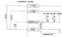
本发明实施例提供一种音视频信号传输接口装置,如图1所示,该装置包括:左声道接口101、右声道接口102、多媒体端子接口103和接地接口104,且在多媒体端子接口103的电路中设置有电压检测点,第一电源105通过第一电阻106连接到电压检测点。在现有技术中,接口装置的线序通常是:左声道接口-右声道接口-多媒体端子接口-接地接口;或者是:左声道接口-右声道接口-接地接口-多媒体端子接口。本发明实施例中的接口装置将以上述两种线序为例进行说明,但应当指出的是,本发明实施例提供的接口装置的线序不仅限于上述两种实现方式,由于工作原理类似,因此在本发明实施例中不再对其他线序类型的接口装置进行详细说明。The embodiment of the present invention provides an audio and video signal transmission interface device, as shown in Figure 1, the device includes: a left channel interface 101, a right channel interface 102, a multimedia terminal interface 103 and a grounding interface 104, and the multimedia terminal interface The circuit at 103 is provided with a voltage detection point, and the first power supply 105 is connected to the voltage detection point through a first resistor 106 . In the prior art, the line sequence of the interface device is usually: left channel interface-right channel interface-multimedia terminal interface-ground interface; or: left channel interface-right channel interface-ground interface-multimedia terminal interface . The interface device in the embodiment of the present invention will be described by taking the above two line sequences as examples, but it should be pointed out that the line sequence of the interface device provided in the embodiment of the present invention is not limited to the above two implementations, because the working principle is similar, Therefore, in the embodiment of the present invention, no detailed description will be given for interface devices of other line sequence types.
为了实现不同类型的设备与音视频信号传输线之间的兼容,本发明实施例提供的接口装置还包括电压检测模块108、判断模块109、控制模块110,以及一端与上述电压检测点连接、另一端与电源连接的第二电阻111。电压检测模块108用于在上述电压检测点处检测插入的音视频信号传输线中多媒体端子的电压值;判断模块109用于根据电压检测模块108的检测结果判断该音视频信号传输线的类型;控制模块110用于根据判断模块109的判断结果进行处理,处理操作可以但不仅限于:控制所述多媒体端子接口与接地接口之间的线序。其中,上述音视频信号传输线的多媒体端子包括音视频端子或麦克端子,音视频端子是音视频数据线中的多媒体端子,麦克端子是耳机中的多媒体端子。为了保证根据检测到的电压值对不同类型的音视频信号传输线进行识别,第二电阻111的阻值要大于音视频端子的内阻值,并小于麦克端子反接时的内阻值。In order to achieve compatibility between different types of equipment and audio and video signal transmission lines, the interface device provided by the embodiment of the present invention also includes a voltage detection module 108, a judgment module 109, a control module 110, and one end is connected to the above-mentioned voltage detection point, and the other end A second resistor 111 connected to the power supply. Voltage detection module 108 is used for detecting the voltage value of the multimedia terminal in the audio-video signal transmission line inserted at the above-mentioned voltage detection point place; Judgment module 109 is used for judging the type of this audio-video signal transmission line according to the detection result of voltage detection module 108; Control module 110 is configured to perform processing according to the judgment result of the judgment module 109, and the processing operation may be but not limited to: control the line sequence between the multimedia terminal interface and the ground interface. Wherein, the multimedia terminal of the audio-video signal transmission line includes an audio-video terminal or a microphone terminal, the audio-video terminal is a multimedia terminal in the audio-video data line, and the microphone terminal is a multimedia terminal in the earphone. In order to identify different types of audio and video signal transmission lines according to the detected voltage values, the resistance of the second resistor 111 should be greater than the internal resistance of the audio and video terminals, and smaller than the internal resistance of the microphone terminal when it is reversed.
本发明实施例提供的接口装置设置在设备侧,具体可以是设备侧的接口,也可以作为独立的装置与设备侧的接口连接,其中判断模块109和控制模块110具体可以由CPU来实现。The interface device provided by the embodiment of the present invention is set on the device side, specifically may be an interface on the device side, or may be connected to the interface on the device side as an independent device, wherein the judging module 109 and the control module 110 may be specifically implemented by a CPU.
本发明实施例中,音视频信号传输线包括三段式耳机、LRMG线序耳机、LRGM线序耳机以及音视频数据线(其线序为LRVG,V是音视频端子)等。通常,第一电阻的阻值范围是1500~3000欧姆;LRMG线序耳机和LRGM线序耳机中的多媒体端子是麦克端子,当麦克端子正接时的内阻值范围是2000~3500欧姆,麦克端子正接时的内阻值是反接时的2~3倍;音视频数据线中的多媒体端子是音视频端子,音视频端子的阻值大约为75欧姆。当音视频信号传输线插入接口装置后,如果由第一电源供电、第一电阻分压,则在第一电源-第一电阻-传输线侧的多媒体端子-接地接口的回路中:(一)由于LRMG线序耳机和LRGM线序耳机的麦克端子正接时的阻值与第一电阻的阻值相差不大,因此,LRMG线序耳机和LRGM线序耳机的麦克端子正接时,耳机侧的分压与第一电阻的分压相差不多;(二)由于三段式耳机中不包括多媒体端子,因此,当三段式耳机插入接口装置后,耳机侧的分压几乎为零;(三)由于LRMG线序耳机和LRGM线序耳机的麦克端子反接时的电阻值、以及音视频数据线的音视频端子的电阻值,与第一电阻的阻值相比要小很多,则相对于第一电阻的分压值也较低,在上述第一电阻分压的回路中,无法区分出LRMG线序耳机和LRGM线序耳机的麦克端子反接,与音视频数据线。此时,可由第二电阻分压,在由第二电阻连接的电源-第二电阻-传输线侧的多媒体端子-接地接口的回路中,测量音视频信号传输线侧的电压值。由于LRMG线序耳机(或LRGM线序耳机)麦克端子反接时的电阻值大于音视频数据线中音视频端子的电阻值,因此,可设置第二电阻的阻值大于音视频端子的电阻值且小于麦克端子反接时的电阻值,以便在由第二电阻分压的回路中区分出,麦克端子反接的LRMG线序耳机(或LRGM线序耳机)或音视频数据线,作为举例而非限定,第二电阻111的阻值范围是150~350欧姆。根据上述各个阻值的取值范围以及对分压关系的分析可知,在第一电阻分压的回路中,LRMG线序耳机(或LRGM线序耳机)的麦克端子正接时,耳机侧的分压值比其他类型的传输线的分压值要大,因此,根据上述阻值特征以及第一电源的供电能力,设置第一阈值,以便根据该第一阈值来判断插入的是否是麦克端子正接时的LRMG线序耳机(或LRGM线序耳机);并根据三段式耳机的上述特征,设置第三阈值(作为举例而非限定,该第三阈值的取值范围是小于0.3伏),用来识别三段式耳机;在第二电阻分压的回路中,由于第二电阻的阻值小于LRMG线序耳机(或LRGM线序耳机)的麦克端子反接时的电阻值且大于音视频数据线的音视频端子的电阻值,因此,可以根据与第二电阻连接的电源的供电能力,以及上述电阻值特征,设置第二阈值,使得第二阈值的取值小于LRMG线序耳机(或LRGM线序耳机)的麦克端子反接时耳机侧的分压且大于视频数据线的音视频端子的分压,以便区分麦克端子反接的LRMG线序耳机(或LRGM线序耳机)或音视频数据线。In the embodiment of the present invention, the audio and video signal transmission lines include three-segment earphones, LRMG line sequence earphones, LRGM line sequence earphones, and audio and video data lines (the line sequence is LRVG, and V is an audio and video terminal) and the like. Usually, the resistance value range of the first resistor is 1500-3000 ohms; the multimedia terminal in the LRMG line-sequence earphone and LRGM line-sequence earphone is a microphone terminal, and the internal resistance range of the microphone terminal is 2000-3500 ohms when the The internal resistance value of the positive connection is 2 to 3 times that of the reverse connection; the multimedia terminal in the audio and video data line is an audio and video terminal, and the resistance of the audio and video terminal is about 75 ohms. After the audio and video signal transmission line is inserted into the interface device, if it is powered by the first power supply and the first resistor divides the voltage, then in the loop of the first power supply-the first resistor-the multimedia terminal on the transmission line side-the ground interface: (1) due to the LRMG The resistance value of the microphone terminal of the line-sequence earphone and LRGM line-sequence earphone is not much different from the resistance of the first resistor. Therefore, when the microphone terminal of the LRMG line-sequence earphone and LRGM line-sequence earphone are directly connected, the divided voltage on the earphone side is the same as that of the first resistor. The voltage division of the first resistor is almost the same; (2) Since the three-segment earphone does not include a multimedia terminal, when the three-segment earphone is inserted into the interface device, the divided voltage on the earphone side is almost zero; (3) Since the LRMG line Compared with the resistance value of the first resistor, the resistance value of the microphone terminal of the sequence earphone and the LRGM line sequence earphone is much smaller than the resistance value of the first resistor. The voltage division value is also low. In the above-mentioned circuit of the first resistor voltage division, it is impossible to distinguish the reverse connection of the microphone terminal of the LRMG line-sequence earphone and the LRGM line-sequence earphone, and the audio and video data line. At this time, the voltage can be divided by the second resistor, and the voltage value on the side of the audio and video signal transmission line can be measured in the loop of the power supply connected by the second resistor-the second resistor-the multimedia terminal on the transmission line side-the ground interface. Since the resistance value of the microphone terminal of the LRMG line-sequence earphone (or LRGM line-sequence earphone) is reversed, it is greater than the resistance value of the audio-video terminal in the audio-video data line, so the resistance value of the second resistor can be set to be greater than the resistance value of the audio-video terminal And less than the resistance value when the microphone terminal is reversed, in order to distinguish in the circuit divided by the second resistor, the LRMG line-sequence earphone (or LRGM line-sequence earphone) or audio and video data line with the microphone terminal reversed, as an example Not limited, the resistance range of the second resistor 111 is 150-350 ohms. According to the value ranges of the above-mentioned resistance values and the analysis of the voltage division relationship, in the circuit of the first resistor voltage division, when the microphone terminal of the LRMG line-sequence earphone (or LRGM line-sequence earphone) is connected, the voltage division on the earphone side The value is larger than the voltage division value of other types of transmission lines. Therefore, according to the above-mentioned resistance characteristics and the power supply capacity of the first power supply, set the first threshold, so as to judge whether the inserted microphone terminal is connected according to the first threshold. LRMG line-sequence earphones (or LRGM line-sequence earphones); and according to the above-mentioned characteristics of the three-segment earphones, set a third threshold (as an example and not a limitation, the value range of the third threshold is less than 0.3 volts) for identification Three-segment earphones; in the circuit of the second resistor voltage divider, since the resistance value of the second resistor is less than the resistance value when the microphone terminal of the LRMG line-sequence earphone (or LRGM line-sequence earphone) is reversed, and is greater than that of the audio and video data line The resistance value of the audio-video terminal, therefore, can set the second threshold value according to the power supply capability of the power supply connected with the second resistance, and the above-mentioned resistance value characteristics, so that the value of the second threshold value is less than the LRMG line sequence earphone (or LRGM line sequence When the microphone terminal of the earphone is reversed, the divided voltage on the earphone side is greater than the divided voltage of the audio and video terminal of the video data line, so as to distinguish the LRMG line-sequence earphone (or LRGM line-sequence earphone) or the audio-video data line with the microphone terminal reversed.
本发明实施例提供的接口装置根据上述设定的阈值识别并处理音视频信号传输线兼容问题的处理过程如下:The interface device provided by the embodiment of the present invention recognizes and handles the audio and video signal transmission line compatibility problem according to the threshold set above, and the processing process is as follows:
当有音视频信号传输线插入上述接口装置后,电压检测模块108测量在第一电阻106接通、且第二电阻111断开时,插入的音视频信号传输线中多媒体端子的第一电压值;判断模块109判断第一电压值是否大于第一阈值或者小于第三阈值,如果是,则判断所述音视频信号传输线是与所述接口装置的接口线序匹配的耳机(与接口装置的接口线序匹配的耳机是指:麦克端子正接的LRMG耳机(或LRGM耳机),或者三段式耳机);否则,触发控制模块110工作(作为举例而非限定,判断模块109可以向控制模块110发送无法识别信号,通过该信号触发控制模块110工作,控制模块110在接收到无法识别信号后,即断开第一电阻分压的回路并接通第二电阻分压的回路),相应的,控制模块110断开第一电阻106,接通第二电阻111,并触发电压检测模块108重新测量电压;相应的,电压检测模块108还根据控制模块110的触发,测量所述音视频信号传输线中多媒体端子的第二电压值;判断模块109还比较所述第二电压值与第二阈值的大小关系,如果所述第二电压值小于或等于所述第二阈值,则判断所述音视频信号传输线为音视频数据线;否则,判断所述音视频信号传输线是与所述接口装置的线序不匹配的耳机(与接口装置的线序不匹配的耳机是指:麦克端子反接的LRMG耳机或LRGM耳机);将判断结果发送给控制模块110(作为举例而非限定,控制模块110可以根据该判断结果识别出相应的传输线类型,进而采取相应的动作);After the audio and video signal transmission line is inserted into the above-mentioned interface device, the voltage detection module 108 measures the first voltage value of the multimedia terminal in the inserted audio and video signal transmission line when the first resistor 106 is turned on and the second resistor 111 is disconnected; Judgment Module 109 judges whether the first voltage value is greater than the first threshold or less than the third threshold, if so, then judges that the audio-video signal transmission line is an earphone (with the interface line sequence of the interface device) that matches the interface line sequence of the interface device The matching earphone refers to: the LRMG earphone (or LRGM earphone) that the microphone terminal is directly connected to, or a three-stage earphone); otherwise, the trigger control module 110 works (as an example and not limitation, the judging module 109 can send an unrecognizable message to the control module 110 signal, the control module 110 is triggered to work by the signal, and after the control module 110 receives the unidentifiable signal, it disconnects the loop of the first resistor voltage divider and connects the loop of the second resistor voltage divider), correspondingly, the control module 110 Disconnect the first resistance 106, connect the second resistance 111, and trigger the voltage detection module 108 to measure the voltage again; The second voltage value; the judging module 109 also compares the size relationship between the second voltage value and the second threshold value, if the second voltage value is less than or equal to the second threshold value, then it is judged that the audio-video signal transmission line is an audio-visual signal transmission line Otherwise, it is judged that the audio and video signal transmission line is an earphone that does not match the line sequence of the interface device (the earphone that does not match the line sequence of the interface device refers to: the LRMG earphone or the LRGM earphone that the microphone terminal is reversely connected to) ); Send the judgment result to the control module 110 (as an example and not limitation, the control module 110 can identify the corresponding transmission line type according to the judgment result, and then take corresponding actions);
如果所述音视频信号传输线是音视频数据线,则控制模块110还断开第二电阻111、接通第一电阻106,并上报音视频数据线插入消息;If the audio-video signal transmission line is an audio-video data line, the control module 110 also disconnects the second resistor 111, connects the first resistor 106, and reports an audio-video data line insertion message;
如果所述音视频信号传输线是与所述接口装置的线序不匹配的耳机,则控制模块110还断开第二电阻111、接通第一电阻106,并切换多媒体端子接口103与接地端口104的线序。其中,切换多媒体端子接口103与接地端口104的线序具体实现方式可以是:通过控制设置在所述多媒体端子接口与所述接地接口之间的模拟开关,切换多媒体端子接口与所述接地接口的线序。相应的,在上述接口装置的多媒体端子接口103与接地接口104之间还包括由电源控制线控制的模拟开关,控制模块110通过切换电源控制线的输出电平来控制该模拟开关切换多媒体自接口与接地接口之间的线序。例如,(一)当电源控制线输出高电平时,模拟开关断开,多媒体端子接口103与接地接口104之间的线序不改变;或者,(二)当电源控制线输出高电平时,模拟开关闭合,多媒体端子接口103与接地接口104之间的线序被切换。在本发明各个实施例中,以上述第(一)中模拟开关控制方式为例进行说明。If the audio and video signal transmission line is an earphone that does not match the line sequence of the interface device, the control module 110 also disconnects the second resistor 111, connects the first resistor 106, and switches the multimedia terminal interface 103 and the ground port 104 line sequence. Wherein, the specific implementation manner of switching the line sequence of the multimedia terminal interface 103 and the grounding port 104 may be: by controlling an analog switch arranged between the multimedia terminal interface and the grounding interface, switching the connection between the multimedia terminal interface and the grounding interface Line order. Correspondingly, an analog switch controlled by the power control line is also included between the multimedia terminal interface 103 and the grounding interface 104 of the above-mentioned interface device, and the control module 110 controls the analog switch to switch the multimedia self-interface by switching the output level of the power control line. The wire sequence between the interface and the ground. For example, (1) when the power control line outputs a high level, the analog switch is disconnected, and the line sequence between the multimedia terminal interface 103 and the ground interface 104 does not change; or (2) when the power control line outputs a high level, the analog switch When the switch is closed, the line sequence between the multimedia terminal interface 103 and the ground interface 104 is switched. In various embodiments of the present invention, the above-mentioned (1) analog switch control method is taken as an example for description.
通过上述处理过程,本发明实施例提供的接口装置能够识别出插入的不同类型的音视频数据传输线,并实现设备与不同类型的音视频数据传输线的兼容。Through the above processing process, the interface device provided by the embodiment of the present invention can identify different types of audio and video data transmission lines inserted, and realize the compatibility of the device with different types of audio and video data transmission lines.
上述本发明实施例提供的接口装置中,增加的第二电阻111可以与第一电阻106并联,由第一电源105供电,即上述与第二电阻106连接的电源是第一电源105。In the interface device provided by the above embodiments of the present invention, the added second resistor 111 can be connected in parallel with the first resistor 106 and powered by the first power supply 105 , that is, the power supply connected to the second resistor 106 is the first power supply 105 .
为了降低电路改动导致的噪声增加等问题,本发明实施例提供的一种优选的实现方式是增加与第二电阻111连接的第二电源112,通过关闭第二电源112来断开第二电阻111;通过打开第二电源112来接通第二电阻111;通过关闭第一电源105来断开第一电阻106;通过接通第一电源105来接通第一电阻106。由于增加了第二电源112,因此对现有的接口电路影响不大,是较为稳定、风险较小的实现方式。In order to reduce problems such as increased noise caused by circuit modification, a preferred implementation method provided by the embodiment of the present invention is to add a second power supply 112 connected to the second resistor 111, and disconnect the second resistor 111 by turning off the second power supply 112 ; turn on the second resistance 111 by turning on the second power supply 112 ; turn off the first resistance 106 by turning off the first power supply 105 ; turn on the first resistance 106 by turning on the first power supply 105 . Since the second power supply 112 is added, it has little influence on the existing interface circuit, and it is a relatively stable and less risky implementation.
下面将对本发明实施例在实际应用过程中的具体实现方式进行详细的说明。The specific implementation manner of the embodiment of the present invention in the actual application process will be described in detail below.
实施例一Embodiment one
在实施例一中,如图2所示的音视频信号传输接口装置的电路示意图,该接口装置线序是:左声道接口-右声道接口-多媒体端子接口-接地接口。且在多媒体端子接口的电路上的电压检测点处设置有第二电源和第二电阻。在默认情况下,第二电源关闭,第一电源打开,且电源控制线输出高电平。In the first embodiment, as shown in FIG. 2 , the circuit schematic diagram of the audio and video signal transmission interface device, the line sequence of the interface device is: left audio channel interface-right audio channel interface-multimedia terminal interface-ground interface. Moreover, a second power supply and a second resistor are arranged at the voltage detection point on the circuit of the multimedia terminal interface. By default, the second power supply is off, the first power supply is on, and the power control line outputs a high level.
当有音视频信号传输线插入该接口装置后,通过在多媒体端子的电路上设置的电压测点(其位置如图2所示)来检测传输线侧的电压值,进而识别并兼容不同类型的传输线。不同类型的音视频数据传输线插入接口装置后的电路示意图如图3~6所示。其中,图3为LRMG线序耳机插入接口装置的电路示意图;图4为LRGM线序耳机插入接口装置的电路示意图;图5为三段式耳机插入接口装置的电路示意图;图6为音视频数据线插入接口装置的电路示意图。When an audio and video signal transmission line is inserted into the interface device, the voltage value on the side of the transmission line is detected through the voltage measuring point (its position as shown in Figure 2) set on the circuit of the multimedia terminal, so as to identify and be compatible with different types of transmission lines. The circuit schematic diagrams after different types of audio and video data transmission lines are inserted into the interface device are shown in FIGS. 3-6 . Among them, Fig. 3 is a schematic circuit diagram of the LRMG line sequence earphone insertion interface device; Fig. 4 is a circuit schematic diagram of the LRGM line sequence earphone insertion interface device; Fig. 5 is a circuit schematic diagram of a three-segment earphone insertion interface device; Fig. 6 is audio and video data Schematic diagram of the circuit where the wire is inserted into the interface device.
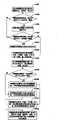
音视频信号传输线插入接口装置后,该接口装置的工作过程如图7所示,包括如下操作:After the audio and video signal transmission line is inserted into the interface device, the working process of the interface device is shown in Figure 7, including the following operations:
S701、电压检测模块在电压测点处测量电压,得到第一电压值,执行S702;S701. The voltage detection module measures the voltage at the voltage measuring point to obtain the first voltage value, and executes S702;
S702、判断模块判断该第一电压值是否大于上述的第一阈值,如果是,则执行S703,否则,执行S704;S702. The judging module judges whether the first voltage value is greater than the above-mentioned first threshold, if yes, execute S703, otherwise, execute S704;
S703、判断模块判断插入的是LRMG线序耳机;S703. The judging module judges that the LRMG line sequence earphone is inserted;
根据S703的判断结果可知,由于其线序与接口装置的接口线序一致,因此不需要接口装置进行任何处理即可实现音频信号的传输;According to the judgment result of S703, since its line sequence is consistent with that of the interface device, audio signal transmission can be realized without any processing by the interface device;
S704、判断模块判断该第一电压值是否小于上述的第三阈值,如果是,则执行S705;否则,向控制模块发送无法识别信令,并执行S706;S704. The judging module judges whether the first voltage value is smaller than the above-mentioned third threshold, and if so, executes S705; otherwise, sends an unidentifiable signaling to the control module, and executes S706;
S705、判断模块判断插入的是三段式耳机;S705. The judging module judges that a three-segment earphone is inserted;
由于S705的判断结果是三段式耳机,三段式耳机的线序与接口装置的接口线序匹配,能够被接口装置兼容;Since the judgment result of the S705 is a three-segment earphone, the line sequence of the three-segment earphone matches the interface line sequence of the interface device, and can be compatible with the interface device;
S706、控制模块接收到无法识别信令后,关闭第一电源,并打开第二电源,由第二电阻分压,执行S707;S706. After the control module receives the unrecognizable signal, turn off the first power supply, and turn on the second power supply, divide the voltage by the second resistor, and execute S707;
S707、电压检测模块测量由第二电阻分压情况下,电压测点处的第二电压值,执行S708;S707. The voltage detection module measures the second voltage value at the voltage measuring point when the voltage is divided by the second resistor, and executes S708;
S708、判断模块判断第二电压值与上述第二阈值的大小关系,如果第二电压值小于或等于第二阈值,则执行S709;否则,执行S710;S708. The judging module judges the magnitude relationship between the second voltage value and the second threshold, and if the second voltage value is less than or equal to the second threshold, execute S709; otherwise, execute S710;
S709、判断模块判断插入的是音视频数据线,并将判断结果发送给控制模块,执行S711;S709, the judging module judges that the audio and video data line is inserted, and sends the judging result to the control module, and executes S711;
S710、判断模块判断插入的是LRGM线序耳机,并将判断结果发送给控制模块,执行S712;S710, the judging module judges that the LRGM line sequence earphone is inserted, and sends the judging result to the control module, and executes S712;
S711、控制模块关闭第二电源,打开第一电源,并上报音视频数据线插入的消息,以便设备侧根据该消息输出音视频信号;S711. The control module turns off the second power supply, turns on the first power supply, and reports a message about the insertion of the audio and video data line, so that the device side outputs audio and video signals according to the message;
其中,由于音视频数据线中的视频回路是复用的,既可以传输音频信号,也可以传输视频信号,因此,当识别出插入的是音视频数据线后,音视频数据线能够与接口装置所在的设备侧兼容。至于具体传输音频信号还是视频信号,则由设备侧决定,不在本发明的讨论范围之内。Among them, since the video circuit in the audio-video data line is multiplexed, it can transmit both audio and video signals. Therefore, when it is recognized that the audio-video data line is inserted, the audio-video data line can communicate with the interface device. The device side where it is located is compatible. Whether to transmit the audio signal or the video signal is determined by the device side, which is not within the scope of the present invention.
S712、控制模块关闭第二电源,接通第一电源,并且通过控制电源控制线输出低电平来切换多媒体端子接口与接地接口之间的线序,其电路示意图如图8所示。S712. The control module turns off the second power supply, turns on the first power supply, and switches the line sequence between the multimedia terminal interface and the ground interface by controlling the power supply control line to output a low level. The circuit schematic diagram is shown in FIG. 8 .
应当指出的是,上述处理过程中,阈值判断的顺序仅是一种举例而非限定。本领域技术人员在不付出创造性劳动的基础上,还可以根据想到按照其他顺序进行阈值判断。It should be noted that, in the above process, the sequence of threshold judgment is only an example and not a limitation. Those skilled in the art may also perform threshold judgments in other sequences as they think of without paying any creative effort.
上述是以LRMG线序的接口装置为例的处理过程。当接口装置的线序是LRVG时,由于视频回路中既可以传输音频信号,也可以传输视频信号,因此,当LRMG线序耳机插入时,仍可兼容,其处理过程同上。The above is the processing process of the interface device with the LRMG line sequence as an example. When the line sequence of the interface device is LRVG, since the audio signal and video signal can be transmitted in the video circuit, when the LRMG line sequence earphone is plugged in, it is still compatible, and the processing process is the same as above.
本发明实施例提供的接口设备通过上述操作能够识别不同类型的音视频数据传输线,进而实现不同类型的设备与音视频数据传输线之间的兼容。The interface device provided by the embodiment of the present invention can identify different types of audio and video data transmission lines through the above operations, thereby achieving compatibility between different types of devices and audio and video data transmission lines.
实施例二Embodiment two
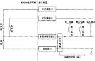
在实施例二中,如图9所示的音视频信号传输接口装置的电路示意图,该接口装置线序是:左声道接口-右声道接口-接地接口-多媒体端子接口(具体可以是LRGM线序)。且在多媒体端子接口的电路上的电压检测点处设置有第二电源和第二电阻。在默认情况下,第二电源关闭,第一电源打开,且电源控制线输出低电平。In the second embodiment, the circuit diagram of the audio-video signal transmission interface device as shown in Figure 9, the line sequence of the interface device is: left channel interface-right channel interface-ground interface-multimedia terminal interface (specifically can be LRGM Line order). Moreover, a second power supply and a second resistor are arranged at the voltage detection point on the circuit of the multimedia terminal interface. By default, the second power supply is turned off, the first power supply is turned on, and the power control line outputs a low level.
由于本发明实施例二提供接口装置中,电源控制线输出低电平,则接地接口与多媒体端子接口的线序被切换,如图9所示,其切换后的实际线序为LRMG。因此,当有音视频信号传输线插入该接口装置后,其处理方式可参照上述实施例一的处理过程。区别仅在于:Since the power control line outputs a low level in the interface device provided by Embodiment 2 of the present invention, the line sequence of the ground interface and the multimedia terminal interface is switched, as shown in FIG. 9 , the actual line sequence after switching is LRMG. Therefore, when an audio and video signal transmission line is inserted into the interface device, its processing method can refer to the processing process of the first embodiment above. The only difference is:
在S712中,本发明实施例二的操作是:控制模块关闭第二电源,接通第一电源,并且通过控制电源控制线输出高电平来切换多媒体端子接口与接地接口之间的线序,使得接口装置的接口线序切换为LRGM。In S712, the operation of the second embodiment of the present invention is: the control module turns off the second power supply, turns on the first power supply, and switches the line sequence between the multimedia terminal interface and the ground interface by controlling the power supply control line to output a high level, Switch the interface line sequence of the interface device to LRGM.
实施例三Embodiment three
在实施例三中,如图10所示的音视频信号传输接口装置的电路示意图,该接口装置线序是:左声道接口-右声道接口-接地接口-多媒体端子接口(具体可以是LRGM线序)。且在多媒体端子接口的电路上的电压检测点处设置有第二电源和第二电阻。在默认情况下,第二电源关闭,第一电源打开,且电源控制线输出高电平。In embodiment three, as shown in Figure 10, the circuit diagram of the audio-video signal transmission interface device, the line sequence of the interface device is: left channel interface-right channel interface-ground interface-multimedia terminal interface (specifically, it can be LRGM Line order). Moreover, a second power supply and a second resistor are arranged at the voltage detection point on the circuit of the multimedia terminal interface. By default, the second power supply is off, the first power supply is on, and the power control line outputs a high level.
通过在多媒体端子的电路上设置的电压测点来检测传输线侧的电压值,进而识别并兼容不同类型的传输线。不同类型的音视频数据传输线插入接口装置后的电路示意图如图11~14所示。其中,图11为LRGM线序耳机插入接口装置的电路示意图;图12为LRMG线序耳机插入接口装置的电路示意图;图13为三段式耳机插入接口装置的电路示意图;图14为音视频数据线插入接口装置的电路示意图。The voltage value on the side of the transmission line is detected by the voltage measuring point set on the circuit of the multimedia terminal, so as to identify and be compatible with different types of transmission lines. The schematic diagrams of circuits after different types of audio and video data transmission lines are inserted into the interface device are shown in FIGS. 11-14 . Among them, Fig. 11 is a schematic circuit diagram of the LRGM line sequence earphone insertion interface device; Fig. 12 is a circuit schematic diagram of the LRMG line sequence earphone insertion interface device; Fig. 13 is a circuit schematic diagram of a three-segment earphone insertion interface device; Fig. 14 is audio and video data Schematic diagram of the circuit where the wire is inserted into the interface device.
音视频信号传输线插入接口装置后,该接口装置的工作过程如图15所示,包括如下操作:After the audio and video signal transmission line is inserted into the interface device, the working process of the interface device is shown in Figure 15, including the following operations:
S1501、电压检测模块在电压测点处测量电压,得到第一电压值,执行S1502;S1501. The voltage detection module measures the voltage at the voltage measuring point to obtain the first voltage value, and executes S1502;
S1502、判断模块判断该第一电压值是否大于上述的第一阈值,如果是,则执行S1503,否则,执行S1504;S1502. The judging module judges whether the first voltage value is greater than the above-mentioned first threshold, if yes, execute S1503, otherwise, execute S1504;
S1503、判断模块判断插入的是LRGM线序耳机;S1503. The judging module judges that the LRGM line sequence earphone is inserted;
根据S1503的判断结果可知,由于其线序与接口装置的线序一致,因此不需要接口装置进行任何处理即可实现音频信号的传输;According to the judgment result of S1503, since its line sequence is consistent with that of the interface device, audio signal transmission can be realized without any processing by the interface device;
S1504、判断模块判断该第一电压值是否小于上述的第三阈值,如果是,则执行S1505;否则,向控制模块发送无法识别信令,并执行S1506;S1504. The judging module judges whether the first voltage value is smaller than the above-mentioned third threshold, and if so, executes S1505; otherwise, sends an unidentifiable signaling to the control module, and executes S1506;
S1505、判断模块判断插入的是三段式耳机;S1505. The judging module judges that a three-segment earphone is inserted;
由于S1505的判断结果是三段式耳机,三段式耳机的线序与接口装置的接口线序匹配,能够被接口装置兼容;Since the judgment result of S1505 is a three-segment earphone, the line sequence of the three-segment earphone matches the interface line sequence of the interface device, and can be compatible with the interface device;
S1506、控制模块接收到无法识别信令后,关闭第一电源,并打开第二电源,由第二电阻分压,执行S1507;S1506. After the control module receives the unrecognizable signal, turn off the first power supply, and turn on the second power supply, divide the voltage by the second resistor, and execute S1507;
S1507、电压检测模块测量由第二电阻分压情况下,电压测点处的第二电压值,执行S1508;S1507. The voltage detection module measures the second voltage value at the voltage measuring point when the voltage is divided by the second resistor, and executes S1508;
S1508、判断模块判断第二电压值与上述第二阈值的大小关系,如果第二电压值小于或等于第二阈值,则执行S1509;否则,执行S1510;S1508. The judging module judges the magnitude relationship between the second voltage value and the above-mentioned second threshold, and if the second voltage value is less than or equal to the second threshold, execute S1509; otherwise, execute S1510;
S1509、由于音视频数据线插入LRGM线序的接口装置后,构成的多媒体端子回路中,音视频端子的阻值仍然是75欧姆,因此判断模块判断插入的是音视频数据线,并将判断结果发送给控制模块,执行S1511;S1509. After the audio-video data line is inserted into the interface device of LRGM line sequence, in the multimedia terminal circuit formed, the resistance value of the audio-video terminal is still 75 ohms, so the judging module judges that the audio-video data line is inserted, and reports the judgment result Send to the control module, execute S1511;
S1510、判断模块判断插入的是LRMG线序耳机,并将判断结果发送给控制模块,执行S1512;S1510. The judging module judges that the inserted LRMG line sequence earphone is inserted, and sends the judging result to the control module, and executes S1512;
S1511、控制模块关闭第二电源,打开第一电源,通过控制电源控制线输出低电平来切换多媒体端子接口与接地接口之间的线序,以便建立视频路,并上报音视频数据线插入的消息,以便设备侧根据该消息输出音视频信号;S1511. The control module turns off the second power supply, turns on the first power supply, and switches the line sequence between the multimedia terminal interface and the ground interface by controlling the power supply control line to output a low level, so as to establish a video channel, and report the insertion of the audio and video data line message, so that the device side outputs audio and video signals according to the message;
其中,由于音视频数据线中的视频回路是复用的,既可以传输音频信号,也可以传输视频信号,因此,当识别出插入的是音视频数据线后,只要控制电源控制线输出低电平,音视频数据线就能够与LRGM线序的接口装置所在的设备侧兼容。至于具体传输音频信号还是视频信号,则由设备侧决定,不在本发明的讨论范围之内。Among them, since the video circuit in the audio and video data line is multiplexed, it can transmit both audio signals and video signals. level, the audio and video data line can be compatible with the device side where the interface device of the LRGM line sequence is located. Whether to transmit the audio signal or the video signal is determined by the device side, which is not within the scope of the present invention.
S1512、控制模块关闭第二电源,接通第一电源,并且通过控制电源控制线输出低电平来切换多媒体端子接口与接地接口之间的线序,其电路示意图如图16所示。S1512. The control module turns off the second power supply, turns on the first power supply, and switches the line sequence between the multimedia terminal interface and the ground interface by controlling the power supply control line to output a low level. The circuit schematic diagram is shown in FIG. 16 .
本发明实施例提供的接口设备通过上述操作能够识别不同类型的音视频数据传输线,进而实现不同类型的设备与音视频数据传输线之间的兼容。The interface device provided by the embodiment of the present invention can identify different types of audio and video data transmission lines through the above operations, thereby achieving compatibility between different types of devices and audio and video data transmission lines.
实施例四Embodiment Four
在实施例四中,如图17所示的音视频信号传输接口装置的电路示意图,该接口装置线序是:左声道接口-右声道接口-多媒体端子-接口接地接口。且在多媒体端子接口的电路上的电压检测点处设置有第二电源和第二电阻。在默认情况下,第二电源关闭,第一电源打开,且电源控制线输出低电平。In Embodiment 4, as shown in FIG. 17 , the circuit schematic diagram of the audio and video signal transmission interface device, the line sequence of the interface device is: left channel interface-right channel interface-multimedia terminal-interface grounding interface. Moreover, a second power supply and a second resistor are arranged at the voltage detection point on the circuit of the multimedia terminal interface. By default, the second power supply is turned off, the first power supply is turned on, and the power control line outputs a low level.
由于本发明实施例四提供接口装置中,电源控制线输出低电平,则接地接口与多媒体端子接口的线序被切换,如图17所示,其切换后的实际线序为LRGM。因此,当有音视频信号传输线插入该接口装置后,其处理方式可参照上述实施例三的处理过程。区别仅在于:Since the power control line outputs a low level in the interface device provided in Embodiment 4 of the present invention, the line sequence of the ground interface and the multimedia terminal interface is switched, as shown in FIG. 17 , the actual line sequence after switching is LRGM. Therefore, when an audio and video signal transmission line is inserted into the interface device, its processing method can refer to the processing process of the third embodiment above. The only difference is:
在S1511中,本发明实施例四的操作是:控制模块关闭第二电源,打开第一电源,通过控制电源控制线输出高电平来切换多媒体端子接口与接地接口之间的线序(使得接口装置的接口线序切换为:左声道接口-右声道接口-多媒体端子-接口接地接口)以便建立视频路,并上报音视频数据线插入的消息,以便设备侧根据该消息输出音视频信号;In S1511, the operation of Embodiment 4 of the present invention is: the control module turns off the second power supply, turns on the first power supply, and switches the line sequence between the multimedia terminal interface and the ground interface by controlling the power supply control line to output a high level (making the interface The interface line sequence of the device is switched to: left channel interface-right channel interface-multimedia terminal-interface grounding interface) in order to establish a video circuit, and report the message of audio and video data line insertion, so that the device side can output audio and video signals according to the message ;
在S1512中,本发明实施例四的操作是:控制模块关闭第二电源,接通第一电源,并且通过控制电源控制线输出高电平来切换多媒体端子接口与接地接口之间的线序,使得接口装置的接口线序切换为:左声道接口-右声道接口-多媒体端子-接口接地接口。In S1512, the operation of Embodiment 4 of the present invention is: the control module turns off the second power supply, turns on the first power supply, and switches the line sequence between the multimedia terminal interface and the ground interface by controlling the power supply control line to output a high level, The interface line sequence of the interface device is switched to: left audio channel interface-right audio channel interface-multimedia terminal-interface grounding interface.
实现上述方法实施例的全部或部分步骤可以通过程序指令相关的硬件来完成,前述的程序可以存储于一计算机可读取存储介质中,该程序在执行时,执行包括上述方法实施例的步骤;而前述的存储介质包括:ROM、RAM、磁碟或者光盘等各种可以存储程序代码的介质。All or part of the steps for realizing the above-mentioned method embodiments can be completed by hardware related to program instructions, and the aforementioned program can be stored in a computer-readable storage medium, and when the program is executed, the steps including the above-mentioned method embodiments are executed; The aforementioned storage medium includes various media capable of storing program codes such as ROM, RAM, magnetic disk or optical disk.
以上所述,仅为本发明较佳的具体实施方式,但本发明的保护范围并不局限于此,任何熟悉本技术领域的技术人员在本发明揭露的技术范围内,可轻易想到的变化或替换,都应涵盖在本发明的保护范围之内。因此,本发明的保护范围应该以权利要求的保护范围为准。The above is only a preferred embodiment of the present invention, but the scope of protection of the present invention is not limited thereto. Any person skilled in the art within the technical scope disclosed in the present invention can easily think of changes or Replacement should be covered within the protection scope of the present invention. Therefore, the protection scope of the present invention should be determined by the protection scope of the claims.
Claims (9)
Translated fromChinesePriority Applications (6)
| Application Number | Priority Date | Filing Date | Title |
|---|---|---|---|
| CN201110059165ACN102164263B (en) | 2011-03-08 | 2011-03-08 | Device and method of audio/video signal transmission interface |
| KR1020137025142AKR101570173B1 (en) | 2011-03-08 | 2012-02-20 | Audio and video signal transmission interface apparatus and method thereof |
| EP12754505.1AEP2677742B1 (en) | 2011-03-08 | 2012-02-20 | Audio-video signal transmission interface device and method |
| JP2013556951AJP5697764B2 (en) | 2011-03-08 | 2012-02-20 | Audio video signal transmission interface apparatus and method |
| PCT/CN2012/071324WO2012119509A1 (en) | 2011-03-08 | 2012-02-20 | Audio-video signal transmission interface device and method |
| US14/020,050US9351076B2 (en) | 2011-03-08 | 2013-09-06 | Audio and video signal transmission interface apparatus and method thereof |
Applications Claiming Priority (1)
| Application Number | Priority Date | Filing Date | Title |
|---|---|---|---|
| CN201110059165ACN102164263B (en) | 2011-03-08 | 2011-03-08 | Device and method of audio/video signal transmission interface |
Publications (2)
| Publication Number | Publication Date |
|---|---|
| CN102164263A CN102164263A (en) | 2011-08-24 |
| CN102164263Btrue CN102164263B (en) | 2012-09-05 |
Family
ID=44465192
Family Applications (1)
| Application Number | Title | Priority Date | Filing Date |
|---|---|---|---|
| CN201110059165AActiveCN102164263B (en) | 2011-03-08 | 2011-03-08 | Device and method of audio/video signal transmission interface |
Country Status (6)
| Country | Link |
|---|---|
| US (1) | US9351076B2 (en) |
| EP (1) | EP2677742B1 (en) |
| JP (1) | JP5697764B2 (en) |
| KR (1) | KR101570173B1 (en) |
| CN (1) | CN102164263B (en) |
| WO (1) | WO2012119509A1 (en) |
Families Citing this family (21)
| Publication number | Priority date | Publication date | Assignee | Title |
|---|---|---|---|---|
| CN102164263B (en)* | 2011-03-08 | 2012-09-05 | 华为终端有限公司 | Device and method of audio/video signal transmission interface |
| CN102395072B (en)* | 2011-10-21 | 2015-08-19 | 惠州Tcl移动通信有限公司 | A kind of headset plug and earphone thereof |
| CN202310052U (en)* | 2011-11-10 | 2012-07-04 | 中兴通讯股份有限公司 | Earphone socket circuit |
| CN103379420B (en)* | 2012-04-18 | 2016-10-05 | 华为终端有限公司 | A kind of method determining earphone line sequence and electronic equipment |
| CN102892060B (en)* | 2012-10-08 | 2016-05-18 | 福建新大陆支付技术有限公司 | Four joint audio port polarity inversion adaptive circuits |
| CN103916152B (en)* | 2012-12-30 | 2016-06-29 | 北京握奇数据系统有限公司 | A kind of obtain the method for audio frequency line sequence, terminal and system |
| CN103916151B (en)* | 2012-12-30 | 2016-03-30 | 北京握奇数据系统有限公司 | A kind of methods, devices and systems obtaining tone frequency channel wire sequence |
| KR101855225B1 (en) | 2014-05-30 | 2018-05-08 | 후아웨이 테크놀러지 컴퍼니 리미티드 | Method, apparatus, and system for supplying power to active noise reduction headset |
| CN106162433B (en)* | 2015-04-10 | 2021-08-24 | 杭州纳雄科技有限公司 | Earphone circuit and control method thereof |
| CN104811644B (en)* | 2015-04-14 | 2018-02-02 | 龙迅半导体(合肥)股份有限公司 | A kind of HDMI transmitters amplitude output signal control circuit |
| US9986351B2 (en)* | 2016-02-22 | 2018-05-29 | Cirrus Logic, Inc. | Direct current (DC) and/or alternating current (AC) load detection for audio codec |
| US9918173B1 (en) | 2016-03-24 | 2018-03-13 | Revx Technologies | Adaptable sound quality device |
| US9716955B1 (en)* | 2016-03-24 | 2017-07-25 | Revx Technologies | Device for monitoring a sound pressure level |
| CN105872897A (en)* | 2016-03-31 | 2016-08-17 | 乐视控股(北京)有限公司 | Tone quality adjusting method and terminal |
| CN105975422B (en)* | 2016-05-27 | 2018-11-23 | 北京小米移动软件有限公司 | A kind of switching equipment, terminal and switching method |
| US10015623B2 (en)* | 2016-06-17 | 2018-07-03 | Nxp B.V. | NFMI based robustness |
| CN109874097B (en)* | 2017-12-05 | 2020-10-30 | 炬芯科技股份有限公司 | Active noise reduction earphone and test system thereof |
| CN113242487B (en)* | 2021-05-11 | 2022-12-02 | 深圳市中科蓝讯科技股份有限公司 | Line control method, line control device, adapter and line control system |
| CN116047613A (en)* | 2021-07-22 | 2023-05-02 | 荣耀终端有限公司 | Method and device for earphone presence detection |
| CN116456134A (en)* | 2022-01-06 | 2023-07-18 | 瑞昱半导体股份有限公司 | Media streaming device and media streaming method |
| CN117640870B (en)* | 2024-01-26 | 2024-06-04 | 荣耀终端有限公司 | Interface anti-reverse insertion circuit, method and electronic equipment |
Citations (3)
| Publication number | Priority date | Publication date | Assignee | Title |
|---|---|---|---|---|
| CN200983638Y (en)* | 2006-12-15 | 2007-11-28 | 康佳集团股份有限公司 | A SCART interface audio output circuit |
| CN101394526A (en)* | 2007-09-21 | 2009-03-25 | 鸿富锦精密工业(深圳)有限公司 | Projection device video signal search method and projection device |
| CN101466008A (en)* | 2007-12-21 | 2009-06-24 | 瑞昱半导体股份有限公司 | Signal receiving method and circuit for judging transmission specification of input signal |
Family Cites Families (17)
| Publication number | Priority date | Publication date | Assignee | Title |
|---|---|---|---|---|
| JP3656334B2 (en)* | 1996-09-05 | 2005-06-08 | ソニー株式会社 | Stereo audio / video device connection device |
| JP2000032339A (en)* | 1998-07-16 | 2000-01-28 | Victor Co Of Japan Ltd | Signal switching circuit |
| US7890284B2 (en)* | 2002-06-24 | 2011-02-15 | Analog Devices, Inc. | Identification system and method for recognizing any one of a number of different types of devices |
| TWI229478B (en)* | 2003-12-24 | 2005-03-11 | Benq Corp | Detecting apparatus and method for an audio/video plug |
| JP4421945B2 (en)* | 2004-05-31 | 2010-02-24 | 京セラ株式会社 | Mobile phone |
| KR100805835B1 (en) | 2006-06-02 | 2008-02-21 | 삼성전자주식회사 | Host system, host interface identification method, and multimedia system including host and host interface |
| JP4191192B2 (en)* | 2005-12-27 | 2008-12-03 | Necインフロンティア株式会社 | Identification method of audio device in portable terminal and portable terminal |
| CN101163220A (en)* | 2006-10-11 | 2008-04-16 | 上海晨兴电子科技有限公司 | Method of automatically detecting video output signal line of mobile phone |
| JP2008182525A (en)* | 2007-01-25 | 2008-08-07 | Funai Electric Co Ltd | Transmitter |
| CN100495377C (en) | 2007-03-09 | 2009-06-03 | 华为技术有限公司 | Method and terminal interface for detecting plugged-in peripheral type |
| JP2008301068A (en)* | 2007-05-30 | 2008-12-11 | Kyocera Corp | Electronics |
| EP2456230B1 (en)* | 2009-02-26 | 2016-02-03 | BlackBerry Limited | Portable electronic device with an audio jack |
| JP5161153B2 (en)* | 2009-05-28 | 2013-03-13 | レノボ・シンガポール・プライベート・リミテッド | Audio device recognition apparatus and portable computer |
| TWI405990B (en)* | 2009-10-21 | 2013-08-21 | Htc Corp | Electronic device and method thereof for identifying electronic accessory |
| TWI455609B (en)* | 2009-10-29 | 2014-10-01 | Htc Corp | Electronic device, electronic system, and method for processing signals from an audio accessory thereof |
| JP2011217228A (en)* | 2010-04-01 | 2011-10-27 | Funai Electric Co Ltd | Electronic device |
| CN102164263B (en)* | 2011-03-08 | 2012-09-05 | 华为终端有限公司 | Device and method of audio/video signal transmission interface |
- 2011
- 2011-03-08CNCN201110059165Apatent/CN102164263B/enactiveActive
- 2012
- 2012-02-20WOPCT/CN2012/071324patent/WO2012119509A1/enactiveApplication Filing
- 2012-02-20EPEP12754505.1Apatent/EP2677742B1/enactiveActive
- 2012-02-20KRKR1020137025142Apatent/KR101570173B1/enactiveActive
- 2012-02-20JPJP2013556951Apatent/JP5697764B2/enactiveActive
- 2013
- 2013-09-06USUS14/020,050patent/US9351076B2/enactiveActive
Patent Citations (3)
| Publication number | Priority date | Publication date | Assignee | Title |
|---|---|---|---|---|
| CN200983638Y (en)* | 2006-12-15 | 2007-11-28 | 康佳集团股份有限公司 | A SCART interface audio output circuit |
| CN101394526A (en)* | 2007-09-21 | 2009-03-25 | 鸿富锦精密工业(深圳)有限公司 | Projection device video signal search method and projection device |
| CN101466008A (en)* | 2007-12-21 | 2009-06-24 | 瑞昱半导体股份有限公司 | Signal receiving method and circuit for judging transmission specification of input signal |
Also Published As
| Publication number | Publication date |
|---|---|
| CN102164263A (en) | 2011-08-24 |
| US9351076B2 (en) | 2016-05-24 |
| EP2677742B1 (en) | 2018-06-27 |
| KR101570173B1 (en) | 2015-11-18 |
| US20140010390A1 (en) | 2014-01-09 |
| EP2677742A1 (en) | 2013-12-25 |
| WO2012119509A1 (en) | 2012-09-13 |
| KR20130124395A (en) | 2013-11-13 |
| EP2677742A4 (en) | 2015-02-11 |
| JP2014512731A (en) | 2014-05-22 |
| JP5697764B2 (en) | 2015-04-08 |
Similar Documents
| Publication | Publication Date | Title |
|---|---|---|
| CN102164263B (en) | Device and method of audio/video signal transmission interface | |
| US20220353433A1 (en) | Determining state signatures for consumer electronic devices coupled to an audio/video switch | |
| US8687798B2 (en) | Microphone line based detection of headset plug removal | |
| CN102761803B (en) | Voice frequency interface self-adaptive device | |
| KR20140047201A (en) | Device and method for detecting insertion of ear-mic phone in terminal | |
| WO2012097615A2 (en) | Multi-purpose connector for multiplexing headset interface into high definition video and audio interface and handheld electronic device | |
| CN103634724A (en) | Earphone connection interface and method of operating earphone, and terminal for supporting the same | |
| US10079688B2 (en) | Network port and ethernet device integrating powered device and power sourcing equivalent in a port | |
| CN105246002A (en) | Data transmission circuit for wire-controlled earphones, mobile terminal and wire-controlled earphones | |
| EP2988480A1 (en) | Automatic configuration of different audio output devices based on a use history | |
| US10615622B2 (en) | Charging detection and control apparatus | |
| WO2018210146A1 (en) | Charging method for charging device, and charging device | |
| CN208077157U (en) | Usb adapter adaptive circuit and terminal device | |
| CN104105046A (en) | Detection circuit | |
| CN211378222U (en) | Audio circuit, head-mounted display equipment and head-mounted display system | |
| CN104254027A (en) | A method and system for using earphones compatible with round hole interface and USB interface | |
| US10194231B2 (en) | Circuit for detecting button action on earphone, terminal, and earphone | |
| CN106412760B (en) | Earphone compatible device | |
| CN103336457B (en) | For eliminating the circuit control system of ground noise of electronic equipment | |
| CN105204817A (en) | Information processing method and electronic equipment | |
| TWI483620B (en) | Method for providing charging, charging control system thereof and electronic device having the same | |
| CN105657613A (en) | Audio output method and device | |
| KR101470232B1 (en) | Device and method for controlling multi-media system for vehicle | |
| TWI813116B (en) | Power capability identification device, electronic device and power capability identification method | |
| CN221930092U (en) | Earphone line sequence matching device and electronic equipment |
Legal Events
| Date | Code | Title | Description |
|---|---|---|---|
| C06 | Publication | ||
| PB01 | Publication | ||
| C10 | Entry into substantive examination | ||
| SE01 | Entry into force of request for substantive examination | ||
| C14 | Grant of patent or utility model | ||
| GR01 | Patent grant | ||
| TR01 | Transfer of patent right | ||
| TR01 | Transfer of patent right | Effective date of registration:20171109 Address after:Metro Songshan Lake high tech Industrial Development Zone, Guangdong Province, Dongguan City Road 523808 No. 2 South Factory (1) project B2 -5 production workshop Patentee after:Huawei terminal (Dongguan) Co.,Ltd. Address before:518129 Longgang District, Guangdong, Bantian HUAWEI base B District, building 2, building No. Patentee before:HUAWEI DEVICE Co.,Ltd. | |
| CP01 | Change in the name or title of a patent holder | Address after:523808 Southern Factory Building (Phase I) Project B2 Production Plant-5, New Town Avenue, Songshan Lake High-tech Industrial Development Zone, Dongguan City, Guangdong Province Patentee after:HUAWEI DEVICE Co.,Ltd. Address before:523808 Southern Factory Building (Phase I) Project B2 Production Plant-5, New Town Avenue, Songshan Lake High-tech Industrial Development Zone, Dongguan City, Guangdong Province Patentee before:Huawei terminal (Dongguan) Co.,Ltd. | |
| CP01 | Change in the name or title of a patent holder | ||
| TR01 | Transfer of patent right | Effective date of registration:20210423 Address after:Unit 3401, unit a, building 6, Shenye Zhongcheng, No. 8089, Hongli West Road, Donghai community, Xiangmihu street, Futian District, Shenzhen, Guangdong 518040 Patentee after:Honor Device Co.,Ltd. Address before:Metro Songshan Lake high tech Industrial Development Zone, Guangdong Province, Dongguan City Road 523808 No. 2 South Factory (1) project B2 -5 production workshop Patentee before:HUAWEI DEVICE Co.,Ltd. | |
| TR01 | Transfer of patent right | ||
| CP03 | Change of name, title or address | Address after:Unit 3401, unit a, building 6, Shenye Zhongcheng, No. 8089, Hongli West Road, Donghai community, Xiangmihu street, Futian District, Shenzhen, Guangdong 518040 Patentee after:Honor Terminal Co.,Ltd. Country or region after:China Address before:3401, unit a, building 6, Shenye Zhongcheng, No. 8089, Hongli West Road, Donghai community, Xiangmihu street, Futian District, Shenzhen, Guangdong Patentee before:Honor Device Co.,Ltd. Country or region before:China | |
| CP03 | Change of name, title or address |