CN102163882B - Method and device for transporting fluid through pipeline by using motor - Google Patents
Method and device for transporting fluid through pipeline by using motorDownload PDFInfo
- Publication number
- CN102163882B CN102163882BCN2011100648970ACN201110064897ACN102163882BCN 102163882 BCN102163882 BCN 102163882BCN 2011100648970 ACN2011100648970 ACN 2011100648970ACN 201110064897 ACN201110064897 ACN 201110064897ACN 102163882 BCN102163882 BCN 102163882B
- Authority
- CN
- China
- Prior art keywords
- stator
- yoke
- teeth
- pressure vessel
- laminations
- Prior art date
- Legal status (The legal status is an assumption and is not a legal conclusion. Google has not performed a legal analysis and makes no representation as to the accuracy of the status listed.)
- Active
Links
- 239000012530fluidSubstances0.000titledescription56
- 238000000034methodMethods0.000titledescription23
- 238000003475laminationMethods0.000claimsabstractdescription82
- 238000004891communicationMethods0.000claimsdescription11
- 230000035699permeabilityEffects0.000claimsdescription9
- 238000004804windingMethods0.000abstractdescription42
- 238000012546transferMethods0.000abstractdescription30
- 230000000116mitigating effectEffects0.000abstract2
- 230000001681protective effectEffects0.000abstract1
- 239000000463materialSubstances0.000description23
- 238000009826distributionMethods0.000description22
- 239000007789gasSubstances0.000description9
- 230000013011matingEffects0.000description9
- 238000005260corrosionMethods0.000description8
- 230000007797corrosionEffects0.000description8
- VNWKTOKETHGBQD-UHFFFAOYSA-NmethaneChemical compoundCVNWKTOKETHGBQD-UHFFFAOYSA-N0.000description8
- 238000003466weldingMethods0.000description7
- 238000005219brazingMethods0.000description6
- 230000006835compressionEffects0.000description6
- 238000007906compressionMethods0.000description6
- 230000004323axial lengthEffects0.000description5
- 238000005538encapsulationMethods0.000description5
- 238000001125extrusionMethods0.000description5
- 238000005266castingMethods0.000description4
- 238000012423maintenanceMethods0.000description4
- 230000017525heat dissipationEffects0.000description3
- 239000003345natural gasSubstances0.000description3
- 239000011295pitchSubstances0.000description3
- 239000000470constituentSubstances0.000description2
- 238000010276constructionMethods0.000description2
- 230000008878couplingEffects0.000description2
- 238000010168coupling processMethods0.000description2
- 238000005859coupling reactionMethods0.000description2
- 230000005672electromagnetic fieldEffects0.000description2
- 238000005242forgingMethods0.000description2
- 239000012535impuritySubstances0.000description2
- 229910001293incoloyInorganic materials0.000description2
- 229910001026inconelInorganic materials0.000description2
- 238000004382pottingMethods0.000description2
- 230000008569processEffects0.000description2
- 238000012545processingMethods0.000description2
- 239000010935stainless steelSubstances0.000description2
- 229910001220stainless steelInorganic materials0.000description2
- 239000000126substanceSubstances0.000description2
- 230000001360synchronised effectEffects0.000description2
- XLYOFNOQVPJJNP-UHFFFAOYSA-NwaterSubstancesOXLYOFNOQVPJJNP-UHFFFAOYSA-N0.000description2
- OKTJSMMVPCPJKN-UHFFFAOYSA-NCarbonChemical compound[C]OKTJSMMVPCPJKN-UHFFFAOYSA-N0.000description1
- 239000004215Carbon black (E152)Substances0.000description1
- RYGMFSIKBFXOCR-UHFFFAOYSA-NCopperChemical compound[Cu]RYGMFSIKBFXOCR-UHFFFAOYSA-N0.000description1
- 229910000881Cu alloyInorganic materials0.000description1
- 230000009471actionEffects0.000description1
- 239000000853adhesiveSubstances0.000description1
- 238000004026adhesive bondingMethods0.000description1
- 230000001070adhesive effectEffects0.000description1
- 230000002411adverseEffects0.000description1
- PNEYBMLMFCGWSK-UHFFFAOYSA-Naluminium oxideInorganic materials[O-2].[O-2].[O-2].[Al+3].[Al+3]PNEYBMLMFCGWSK-UHFFFAOYSA-N0.000description1
- 229910052799carbonInorganic materials0.000description1
- 239000000919ceramicSubstances0.000description1
- 239000002131composite materialSubstances0.000description1
- 238000001816coolingMethods0.000description1
- 229910052802copperInorganic materials0.000description1
- 239000010949copperSubstances0.000description1
- 230000007423decreaseEffects0.000description1
- 230000008030eliminationEffects0.000description1
- 238000003379elimination reactionMethods0.000description1
- 230000007613environmental effectEffects0.000description1
- 230000005284excitationEffects0.000description1
- 230000004907fluxEffects0.000description1
- 229930195733hydrocarbonNatural products0.000description1
- 150000002430hydrocarbonsChemical class0.000description1
- 238000007654immersionMethods0.000description1
- 230000006698inductionEffects0.000description1
- 230000003993interactionEffects0.000description1
- 238000002955isolationMethods0.000description1
- 238000005304joiningMethods0.000description1
- 238000010030laminatingMethods0.000description1
- 238000004519manufacturing processMethods0.000description1
- 230000007246mechanismEffects0.000description1
- 239000002184metalSubstances0.000description1
- 229910052751metalInorganic materials0.000description1
- 230000004048modificationEffects0.000description1
- 238000012986modificationMethods0.000description1
- 230000007935neutral effectEffects0.000description1
- 238000009828non-uniform distributionMethods0.000description1
- 239000003921oilSubstances0.000description1
- 239000004800polyvinyl chlorideSubstances0.000description1
- 239000005060rubberSubstances0.000description1
- 238000005245sinteringMethods0.000description1
- 238000009987spinningMethods0.000description1
- 238000009827uniform distributionMethods0.000description1
Images


Classifications
- H—ELECTRICITY
- H02—GENERATION; CONVERSION OR DISTRIBUTION OF ELECTRIC POWER
- H02K—DYNAMO-ELECTRIC MACHINES
- H02K5/00—Casings; Enclosures; Supports
- H02K5/04—Casings or enclosures characterised by the shape, form or construction thereof
- H02K5/12—Casings or enclosures characterised by the shape, form or construction thereof specially adapted for operating in liquid or gas
- H02K5/128—Casings or enclosures characterised by the shape, form or construction thereof specially adapted for operating in liquid or gas using air-gap sleeves or air-gap discs
- H—ELECTRICITY
- H02—GENERATION; CONVERSION OR DISTRIBUTION OF ELECTRIC POWER
- H02K—DYNAMO-ELECTRIC MACHINES
- H02K1/00—Details of the magnetic circuit
- H02K1/06—Details of the magnetic circuit characterised by the shape, form or construction
- H02K1/12—Stationary parts of the magnetic circuit
- H02K1/16—Stator cores with slots for windings
- H—ELECTRICITY
- H02—GENERATION; CONVERSION OR DISTRIBUTION OF ELECTRIC POWER
- H02K—DYNAMO-ELECTRIC MACHINES
- H02K3/00—Details of windings
- H02K3/46—Fastening of windings on the stator or rotor structure
- H02K3/50—Fastening of winding heads, equalising connectors, or connections thereto
- H—ELECTRICITY
- H02—GENERATION; CONVERSION OR DISTRIBUTION OF ELECTRIC POWER
- H02K—DYNAMO-ELECTRIC MACHINES
- H02K5/00—Casings; Enclosures; Supports
- H02K5/04—Casings or enclosures characterised by the shape, form or construction thereof
- H02K5/18—Casings or enclosures characterised by the shape, form or construction thereof with ribs or fins for improving heat transfer
- H—ELECTRICITY
- H02—GENERATION; CONVERSION OR DISTRIBUTION OF ELECTRIC POWER
- H02K—DYNAMO-ELECTRIC MACHINES
- H02K9/00—Arrangements for cooling or ventilating
- H02K9/22—Arrangements for cooling or ventilating by solid heat conducting material embedded in, or arranged in contact with, the stator or rotor, e.g. heat bridges
- H02K9/223—Heat bridges
- H—ELECTRICITY
- H02—GENERATION; CONVERSION OR DISTRIBUTION OF ELECTRIC POWER
- H02K—DYNAMO-ELECTRIC MACHINES
- H02K9/00—Arrangements for cooling or ventilating
- H02K9/19—Arrangements for cooling or ventilating for machines with closed casing and closed-circuit cooling using a liquid cooling medium, e.g. oil
- H02K9/197—Arrangements for cooling or ventilating for machines with closed casing and closed-circuit cooling using a liquid cooling medium, e.g. oil in which the rotor or stator space is fluid-tight, e.g. to provide for different cooling media for rotor and stator
Landscapes
- Engineering & Computer Science (AREA)
- Power Engineering (AREA)
- Physics & Mathematics (AREA)
- Thermal Sciences (AREA)
- Iron Core Of Rotating Electric Machines (AREA)
- Windings For Motors And Generators (AREA)
- Motor Or Generator Frames (AREA)
- Connection Of Motors, Electrical Generators, Mechanical Devices, And The Like (AREA)
- Pipeline Systems (AREA)
- Motor Or Generator Cooling System (AREA)
Abstract
Description
Translated fromChinese本案是专利申请号200710106486.7、申请日为2007年6月1日的同名申请的分案申请。This case is a divisional application of the patent application No. 200710106486.7 with the same title filed on June 1, 2007.
技术领域technical field
本发明总体涉及流体输送系统,更具体地说涉及用于采用电机通过管路输送流体的方法和装置。The present invention relates generally to fluid transfer systems, and more particularly to methods and apparatus for transferring fluid through tubing using electric motors.
背景技术Background technique
流体输送用于多种不同的工业,包括但不局限于化学、油气工业。在一种已知的流体输送应用中,流体从陆上或海面地点输送到加工厂用于后续使用。在其它已知应用中,流体输送用于碳氢化合物加工工业和化学工业并便于向终端使用者的分配。Fluid transfer is used in many different industries including, but not limited to, the chemical, oil and gas industries. In one known fluid transfer application, fluid is transferred from an onshore or offshore location to a processing plant for subsequent use. Among other known applications, fluid transport is used in the hydrocarbon processing and chemical industries and facilitates distribution to end users.
至少一些已知的流体输送站采用由燃气轮机驱动的流体输送装置例如压缩机、风扇和/或泵。一些这样的气轮机通过齿轮箱驱动相关流体输送装置,该齿轮箱将燃气轮机输出驱动轴速度提高或降低到预定装置的驱动轴速度。电机(也就是电驱动的电动机或电子驱动装置)与机械驱动装置(也就是燃气轮机)相比在操作灵活性(例如变速)、可维护性、更低的投资成本和更低的操作成本、更高的效率和环境相容性方面具有优势。另外,电子驱动装置通常在构造上比机械驱动装置更简单、通常需要更小的基底面、可以更容易与流体输送装置结合、可以省去对齿轮箱的需要、和/或可以比机械驱动装置更可靠。At least some known fluid transfer stations employ fluid transfer devices such as compressors, fans, and/or pumps driven by gas turbines. Some of these gas turbines drive an associated fluid delivery device through a gearbox that increases or decreases the gas turbine output drive shaft speed to the drive shaft speed of the intended device. Electric motors (i.e. electrically driven electric motors or electronic drives) have advantages over mechanical drives (i.e. gas turbines) in terms of operational flexibility (e.g. variable speed), maintainability, lower capital and operating costs, more It has advantages in terms of high efficiency and environmental compatibility. Additionally, electronic drives are typically simpler in construction than mechanical drives, typically require a smaller footprint, can be more easily integrated with fluid delivery devices, can eliminate the need for gearboxes, and/or can be more compact than mechanical drives. more reliable.
然而,采用电子驱动装置的系统会比采用机械驱动装置的那些系统具有更低的效率。影响电子驱动装置效率的至少一些因素包括电动机驱动装置和驱动控制装置的电气和电子布局、供电电源的质量和效率、电子驱动部件(例如定子)的尺寸和重量以及磁偶联强度。而且,流体输送装置的电子驱动装置通过驱动部件在例如定子内产生热量,并且需要辅助的系统以便于散热。例如,一些已知的电子驱动装置采用所输送的流体作为主要热传递介质并引导流体穿过和环绕定子。然而,在一些情况下,所输送的流体会具有侵入成分或杂质,从而对所采用的部件的效率产生不利影响。However, systems employing electronic drives may have lower efficiencies than those employing mechanical drives. At least some of the factors that affect the efficiency of an electronic drive include the electrical and electronic layout of the motor drive and drive controls, the quality and efficiency of the power supply, the size and weight of the electronic drive components (eg, the stator), and the strength of the magnetic coupling. Furthermore, the electronic drive of the fluid delivery device generates heat through the drive components, eg in the stator, and requires an auxiliary system to dissipate the heat. For example, some known electric drives employ transported fluid as the primary heat transfer medium and direct the fluid through and around the stator. However, in some cases, the delivered fluid can have intrusive constituents or impurities that can adversely affect the efficiency of the employed components.
发明内容Contents of the invention
一方面,提供一种用于电机的定子组件。该定子组件包括包括压力容器,在其中限定了至少一个封装件。该定子组件还包括在压力容器内的轭,其包括多个元件。每个所述元件包括至少一个配合表面并且所述元件沿配合表面可拆除地连接在一起。该定子组件还包括在轭内限定了多个槽的多个齿,使得在相邻齿之间限定了槽。In one aspect, a stator assembly for an electric machine is provided. The stator assembly includes a pressure vessel defining at least one enclosure therein. The stator assembly also includes a yoke within the pressure vessel that includes a plurality of elements. Each of the elements includes at least one mating surface and the elements are removably connected together along the mating surface. The stator assembly also includes a plurality of teeth defining a plurality of slots within the yoke such that slots are defined between adjacent teeth.
另一方面,提供一种用于电机的定子组件。该定子组件包括压力容器和与压力容器热连通以便于从定子组件中散热的轭。该定子组件还包括具有多个叠层的多个齿。所述多个叠层包括至少一个具有第一导热率和第一导磁率的第一叠层以及至少一个具有第二导热率和第二导磁率的第二叠层。第一导热率不同于第二导热率并且第一导磁率不同于第二导磁率。第二叠层包括在所述多个齿内以第一预定轴向厚度径向延伸的第一部分以及在所述轭内以第二预定轴向厚度径向延伸的第二部分。第二部分与压力容器热连通以便于从定子组件中散热。In another aspect, a stator assembly for an electric machine is provided. The stator assembly includes a pressure vessel and a yoke in thermal communication with the pressure vessel to facilitate removal of heat from the stator assembly. The stator assembly also includes a plurality of teeth having a plurality of laminations. The plurality of laminations includes at least one first lamination having a first thermal conductivity and a first magnetic permeability and at least one second lamination having a second thermal conductivity and a second magnetic permeability. The first thermal conductivity is different from the second thermal conductivity and the first magnetic permeability is different from the second magnetic permeability. The second lamination includes a first portion extending radially within the plurality of teeth with a first predetermined axial thickness and a second portion extending radially within the yoke with a second predetermined axial thickness. The second portion is in thermal communication with the pressure vessel to facilitate removal of heat from the stator assembly.
另一方面,提供一种流体输送站。该流体输送站包括流体输送组件。所述流体输送组件包括至少一个旋转轴。所述站还包括具有转子组件和定子组件的驱动电动机,定子组件包括压力容器、轭和多个齿。压力容器包括在其中限定的至少一个封装件,并且所述轭包括多个元件。每个元件包括至少一个配合表面并且所述元件沿配合表面可拆除地连接在一起。所述轭处于压力容器内。所述多个齿限定了多个槽,使得在相邻齿之间限定了槽。所述多个齿处于所述轭内。转子与定子组件磁连接。驱动电动机的转子组件与流体输送组件的至少一个旋转轴旋转连接。In another aspect, a fluid transfer station is provided. The fluid transfer station includes a fluid transfer assembly. The fluid delivery assembly includes at least one rotational shaft. The station also includes a drive motor having a rotor assembly and a stator assembly including a pressure vessel, a yoke, and a plurality of teeth. The pressure vessel includes at least one enclosure defined therein, and the yoke includes a plurality of elements. Each element includes at least one mating surface and the elements are removably connected together along the mating surface. The yoke is inside a pressure vessel. The plurality of teeth define a plurality of slots such that slots are defined between adjacent teeth. The plurality of teeth are within the yoke. The rotor is magnetically connected to the stator assembly. The rotor assembly of the drive motor is rotatably coupled to at least one rotational shaft of the fluid delivery assembly.
附图说明Description of drawings
图1是示意性流体输送站的横截面示意图;Figure 1 is a schematic cross-sectional view of an exemplary fluid transfer station;
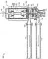
图2是可以用于图1所示流体输送站的示意性电动机的横截面示意图;Figure 2 is a schematic cross-sectional view of an exemplary motor that may be used in the fluid transfer station shown in Figure 1;
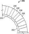
图3是可以用于图2所示电动机的示意性定子封装件一部分的偏斜轴向示意图;Figure 3 is a skewed axial view of a portion of an exemplary stator package that may be used with the motor shown in Figure 2;
图4是可以用于图2所示电动机的示意性定子组件的示意性齿部的偏斜轴向示意图;Fig. 4 is a skewed axial schematic view of an exemplary tooth portion of the exemplary stator assembly that may be used in the electric motor shown in Fig. 2;
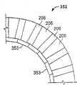
图5是可以用于图2所示电动机的备选封装件齿部的一部分的轴向示意图;Figure 5 is an axial schematic view of a portion of an alternative package tooth section that may be used with the motor shown in Figure 2;
图6是可以用于图2所示电动机的备选封装件齿部的一部分的轴向示意图;Figure 6 is an axial schematic view of a portion of an alternative package tooth section that may be used with the motor shown in Figure 2;
图7是可以用于图2所示电动机的备选封装件齿部的一部分的轴向示意图;Figure 7 is an axial schematic view of a portion of an alternative package tooth section that may be used with the motor shown in Figure 2;
图8是可以用于图2所示电动机的备选封装件齿部的一部分的轴向示意图;Figure 8 is an axial schematic view of a portion of an alternative package tooth section that may be used with the motor shown in Figure 2;
图9是可以用于图2所示电动机的示意性定子组件的示意性轭部的偏斜轴向示意图;Figure 9 is a skewed axial view of an illustrative yoke that may be used with the illustrative stator assembly of the electric motor shown in Figure 2;
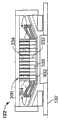
图10是可以用于图2所示电动机的示意性定子组件的多个热传导叠层的横截面示意图;10 is a schematic cross-sectional view of a plurality of thermally conductive laminations that may be used in the exemplary stator assembly of the electric motor shown in FIG. 2;
图11是可以用于图2所示电动机的备选定子的横截面示意图,该定子轭部中的多个热传导叠层比齿部中的热传导叠层更厚;11 is a schematic cross-sectional view of an alternative stator that may be used in the motor shown in FIG. 2, the stator having a plurality of thermally conductive laminations thicker in the yoke than in the teeth;
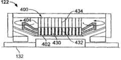
图12是可以用于图2所示电动机的备选定子的横截面示意图,该定子齿部中的多个热传导叠层比轭部中的热传导叠层更厚;12 is a schematic cross-sectional view of an alternative stator that may be used in the motor shown in FIG. 2, the stator having a plurality of thermally conductive laminations thicker in the teeth than in the yoke;
图13是可以用于图2所示电动机的具有变化的轴向节距的多个备选热传导定子叠层的横截面示意图;13 is a schematic cross-sectional view of a number of alternative thermally conductive stator laminations with varying axial pitches that may be used in the motor shown in FIG. 2;
图14是可以用于图2所示电动机的多个示意性电枢绕组的横截面示意图;14 is a schematic cross-sectional view of a plurality of exemplary armature windings that may be used in the motor shown in FIG. 2;
图15是可以用于图2所示电动机上的定子齿部与定子封装件中心部分相连的偏斜轴向示意图;Fig. 15 is a skewed axial schematic view of the stator teeth connected to the central part of the stator package that can be used on the motor shown in Fig. 2;
图16是可以用于图2所示电动机的多个示意性电枢绕组的横截面轴向示意图;Fig. 16 is a schematic cross-sectional axial view of a plurality of exemplary armature windings that may be used in the motor shown in Fig. 2;
图17是可以用于图2所示电动机上的多个轭部连接在多个电枢绕组上以形成示意性定子芯部的横截面轴向示意图;Fig. 17 is a schematic cross-sectional axial view of a plurality of yokes connected to a plurality of armature windings to form an exemplary stator core that may be used in the motor shown in Fig. 2;
图18是可以用于图2所示电动机的示意性压力容器的偏斜轴向示意图;以及Figure 18 is a skewed axial view of an exemplary pressure vessel that may be used with the motor shown in Figure 2; and
图19是可以用于图2所示电动机的示意性压力容器的轴向示意图。FIG. 19 is an axial schematic view of an exemplary pressure vessel that may be used with the electric motor shown in FIG. 2 .
具体实施方式Detailed ways
图1是示意性流体输送站100的横截面示意图。在示意性实施方式中,站100是包括流体输送组件102的埋入式天然气压缩站100。在示意性实施方式中,组件102是与电驱动电动机104旋转相连的多级压缩机102。备选地,组件102可以是但不局限于泵或风扇。站100可以定位在任何地理位置并可以便于在其中得到预定操作参数的任何流体的输送。可以通过站100输送的流体的示例但不局限于从天然源(图1中未示出)引导到站100的未处理的甲烷。FIG. 1 is a schematic cross-sectional view of an exemplary
在示意性实施方式中,电动机104是永久磁铁式电动机,其被设计成操作速度通常与由60Hz的电源供电的同步电动机相关联处于3600转/分钟最大速度之上。因此,电动机104通常被称为“超同步”电动机。更具体地说,在示意性实施方式中,电动机104包括多个与备选驱动机构相比有利的特征。例如,在示意性实施方式中,电动机104在不采用附加部件例如齿轮箱的情况下可以获得范围在大约8,000转/分钟-20,000转/分钟的速度以便于增大输出速度。备选地,可以采用超过20,000rpm的电动机104的速度。速度增大便于气体快速增压,由此提高压缩站100的效率和效能。另外,在该实施方式中,省去附加部件例如齿轮箱导致站100需要更小的基底面并省去相关的维护。该实施方式另一特征是省去磨损部件例如碳基滑环。因此,在示意性实施方式中,压缩站100的可靠性便于与电动机104一起得到提高。备选地,电动机104可以是永久磁铁式同步电动机、单独激磁电动机、感应电动机、或获得预定操作参数并使站100能够起到在此所述的作用的任何其它驱动装置。In the exemplary embodiment, the
压缩机102定位并可靠固定在压缩机壳体103内。电动机104定位并可靠固定在压力容器105内。在示意性实施方式中,壳体103和压力容器105被制造成单独的部件并且通过本领域已知的方法连接在一起。备选地,壳体103和压力容器105可以被制造成一体(整体)元件。同样,在示意性实施方式中,壳体103和压力容器105通过铸造或锻造过程制成。备选地,壳体103和压力容器105可以采用本领域已知的任何方法制成,例如使壳体103和压力容器105能够如在此所述的那样得到制造和组装的焊接过程。壳体103包括压缩机吸入固定件108,其与进口管路110流体连通。管路110可以由金属、橡胶、聚氯乙烯(PVC)或获得与输送流体有关的预定操作参数以及站100的位置的任何材料制成。The
在示意性实施方式中,站100还包括与壳体103相连并从壳体103向外延伸的压缩机端部件112。端部件112便于在压缩机102插入壳体103之后将压缩机102封装在站100内并包括压缩机排放固定件114,其连接成与同进口管路110基本上类似的压缩机出口管路116流体连通。另外,电动机端盖组件118与压力容器105固定相连。端盖118便于在电动机104插入压力容器105内之后将电动机104封装在站100内。In the exemplary embodiment,
电动机104包括转子组件120和定子组件122,它们定位成使得在定子组件122与转子组件120之间限定了间隙124。定位在电缆管道126内的多个供电电缆便于连接站100与电源例如变频驱动装置(VFD)(在图1中未示出)。当定子组件122通电时,在电动机104内感应电磁场。间隙124便于转子组件120与定子组件122的磁性连接以产生在转子组件120中引起旋转的转矩。
压缩机102包括与转子组件120旋转连接的可旋转驱动轴128。在示意性实施方式中,压缩机102包括多个压缩机级130。备选地,压缩机102可以仅包括一级。转子组件120和轴128可以绕旋转轴线132旋转。系统100还包括便于减小电动机压力容器125与压缩机壳体103之间流体连通的电动机-压缩机壳体密封件137。旋转轴线132可以处于便于获得站100预定操作参数的任何定向,包括但不局限于水平和垂直定向。
在操作过程中,VFD在预定电压和频率下向定子组件122供给多相交流电。在定子组件122中产生旋转电磁场(在图1中未示出)。通过包括但不局限于永久磁铁和外部激磁的方法在转子组件120内产生第二磁场。转子组件120与定子组件122中的磁场通过间隙124的相互作用引起转矩并随后引起转子组件120的旋转。During operation, the VFD supplies multi-phase alternating current to the
站100在第一预定压力下通过进口管路110接收天然气。该气体通过吸入固定件108被引导到压缩机102。气体随后流入压缩机102并在大于第一预定压力的第二预定压力下被压缩到更大的密度和更小的体积。得到压缩的气体通过排放固定件114排入出口管路116。
图2是可以用于流体输送站100的示意性电动机104的横截面示意图。如上所述,电动机104包括端盖组件118、转子组件120、定子组件122、间隙124、电缆管道126、轴线132和密封件137。压力容器105封装电动机104。FIG. 2 is a schematic cross-sectional view of an
转子120包括中心部分140。中心部分可以包括但不局限于封装在部分140周围的多个永久磁铁或多个激磁绕组(在图2中都未示出)。转子120还包括外侧主轴部分142和内侧主轴部分143。同样,部分142和143与部分140相连,使得在部分140内引起的旋转力引起部分142和143以及部分140的旋转。The
电动机104还包括与压力容器105相连的外侧轴承146和内侧轴承148。轴承146和148便于转子组件120通过转子部分142和143的径向定位。在示意性实施方式中,轴承146和148是被构造成作为主动式磁性轴承的磁性轴承146和148。更具体地说,采用控制子系统(在图2中未示出)与磁性轴承146和148结合以确定在任何给定时刻旋转轴承部件(在图2中未示出)相对于固定部件(在图2中未示出)的径向位置并便于进行磁调节以修正在任何给定角位置下产生的任何偏离。磁性轴承146和148便于转子组件120在上述与示意性电动机104相关的高速下的操作。备选地,可以采用包括但不局限于例如径向轴承的非磁性轴承获得包括但不局限于减小的振动和摩擦损失的预定参数。至少一个破旧的轴承(在图2中未示出)可以以与轴承146和148类似的方式定位在电动机104内以便于在轴承146和/或148失效时对转子组件120提供径向支承。此外,至少一个止推轴承(在图2中未示出)可以以与轴承146和148类似的方式定位在电动机104内以便于减小转子组件120和轴128(在图1中示出)的轴向推力作用。The
在示意性实施方式中,定子组件122至少部分地封装在定子封装件150内。图3是可以用于电动机104(在图2中示出)的示意性定子封装件150的一部分的偏斜轴向示意图。参照图3并结合图2描述封装件150。为了观察在图3中示出了转子104的旋转轴线132。In the illustrated embodiment,
可以采用站100输送具有主动侵入属性和/或杂质的流体。这些流体可以被引入压力容器105内以润滑和/或冷却电动机104的部件。封装件150便于使定子122与在压力容器105内循环的流体隔离。
封装件150包括径向定位在间隙124内的中心部分152。在示意性实施方式中,中心部分152基本上是圆柱形的。下文描述备选的实施方式。中心部分152包括径向内表面154和径向外表面156。定子组件122的至少一部分可以接触外表面156。内表面154和转子部分140的外周限定了环形间隙124。与用于制造部分152的材料相关的参数包括但不局限于非导电性、磁中和性以及具有足够的强度和抗腐蚀性以减小部分152在操作过程中的变形和腐蚀并且还可以包括便于热传导的特性。部分152可以由包括但不局限于氧化铝基陶瓷合成物的材料制成。
封装件150还可以包括两个扩口部分,也就是外侧扩口部分158和内侧扩口部分160,它们与圆柱形部分152相连并从其上径向和轴向延伸。在示意性实施方式中,部分158和160可以基本上是圆锥形的。部分158和160分别定位在磁性轴承146和148与定子组件122的至少一部分之间。部分158包括径向内表面162和径向外表面164。部分160包括径向内表面166和径向外表面168。与用于制造部分158和160的材料相关的参数包括但不局限于具有足够的强度和抗腐蚀性以减小部分158和160在操作过程中的变形和腐蚀并且还可以包括便于热传导的特性。部分158和160可以由包括但不局限于Incoloy

在示意性实施方式中,部分152和158由类似材料制成,采用包括但不局限于将部分158焊接或钎焊在部分152上或将部分158和部分152铸造成整体部分(在图2和3中未示出)的方法将这两个部分在它们的分界处连接起来。随后,由与部分158和部分152不同的材料制成的部分160在与部分158轴向相对一侧与部分152相连。基本上环形的密封件170固定在部分152和部分160的分界面,从而便于定子122与在压力容器105内输送的流体分隔。密封件170可以由具有包括但不局限于便于与部分152和160的材料属性形成材料和操作上的相容性以及便于获得与电动机104相关的预定操作参数的那些属性的材料制成。In the exemplary embodiment,
备选地,部分152和160由类似材料制成,采用可以包括但不局限于将部分160焊接或钎焊在部分152上或将部分160和部分152铸造成整体部分(在图2和3中未示出)的方法将这两个部分在它们的分界处连接起来。随后,由与部分160和152不同的材料制成的部分158在与部分160轴向相对一侧与部分152相连。基本上与密封件170类似的基本上环形的密封件(在图2和3中未示出)固定在部分158和152的分界面上,从而便于定子122与在压力容器105内输送的流体的分隔。Alternatively,
同样,备选地,部分158和160可以由不同于部分152的材料制成。在该备选实施方式中,多个基本上环形的密封件170固定在部分152和160以及152和158的分界面上。另外,备选地,部分152,158和160可以由类似材料制成,采用上述方法在它们的分界处进行连接。Also,
在示意性实施方式中,部分152基本上是圆柱形的并且部分158和160基本上是圆锥形的。备选地,部分152,158和160可以是便于获得与电动机104和站100相关的预定操作参数的任何几何构造的组合(下文进一步论述)。In the exemplary embodiment,
图4是可以用于电动机104(在图2中示出)示意性定子组件122的示意性齿部202的偏斜轴向示意图。参照图4并结合图2描述封装件齿部202。为了观察在图4中示出了转子104的旋转轴线132。4 is a skewed axial schematic illustration of an
定子组件122包括基本上圆柱形的定子芯部200。芯部200定位在由压力容器105和封装件150限定的定子组件容室172的至少一部分内(下文进一步论述)。芯部200包括基本上圆柱形的齿部202和基本上圆柱形的轭部204。齿部202包括多个相邻的定子齿206,其中相邻的齿206限定了多个相邻的定子绕组槽208。The
每个齿206通过本领域已知的方法层叠单个叠层(在图2和4中未示出)制成以形成具有预定轴向和径向尺寸的齿。齿206与封装件齿部的径向外表面156圆周固定相连,使得绕组槽208形成为具有预定轴向和径向尺寸。在示意性实施方式中,齿206采用舌突和凹槽结构(在图2和4中未示出)经过轴向槽定位在表面156上。备选地,齿206采用可以包括但不局限于焊接、钎焊和粘结剂的方法与表面156相连。Each
在示意性实施方式中,封装件中心部分152是圆柱形的。备选地,封装件中心部分152可以形成为具有预定多边形尺寸。图5是可以用于电动机104(在图2中示出)的备选封装件齿部252的一部分的轴向示意图。备选的部分252是包括多个挤压区段253的挤压多边形。在该备选实施方式中,挤压区段253的尺寸和位置被设计成使得区段253在槽208上基本上居中并且区段253的数量等于槽208的数量。而且,在该备选实施方式中,区段253和齿206的尺寸和位置被设计成使得挤压多边形部分252的顶点在齿206上基本上居中。In the illustrated embodiment, enclosure
图6是可以用于电动机104(在图2中示出)的备选封装件齿部352的一部分的轴向示意图。备选的部分352是包括多个挤压区段353的挤压多边形。在该备选实施方式中,挤压区段353的尺寸和位置被设计成使得区段353在齿206上基本上居中并且区段353的数量等于槽208的数量。而且,在该备选实施方式中,区段353和槽208的尺寸和位置被设计成挤压多边形部分352的顶点在槽208上基本上居中。FIG. 6 is an axial schematic illustration of a portion of an
图7是可以用于电动机104(在图2中示出)的备选封装件齿部452的一部分的轴向示意图。备选的部分452是包括多个挤压区段453的挤压多边形。在该备选实施方式中,挤压区段453的尺寸和位置被设计成使得一部分区段453在齿206上基本上居中并且一部分区段453以交替方式在槽208上基本上居中。而且,在该备选实施方式中,区段453的数量等于齿206的数量与槽208的数量的总和。FIG. 7 is an axial schematic illustration of a portion of an
图8是可以用于电动机104(在图2中示出)的备选封装件齿部552的一部分的轴向示意图。备选的部分552的几何形状可以是但不局限于直圆柱体或挤压多边形。在该备选实施方式中,部分552包括限定在径向外表面556内的多个槽553,其中槽553的数量等于齿208的数量。槽553包括便于容纳齿206的预定轴向和径向尺寸,由此便于齿206的圆周对准。FIG. 8 is an axial schematic illustration of a portion of an
图9是可以用于电动机104(在图2中示出)的示意性定子组件122的示意性定子芯部200的示意性轭部204的偏斜轴向示意图。为了观察示出了转子104的旋转轴线132。参照图9并结合图2描述轭部204。在示意性实施方式中,轭部204包括两个基本上类似的轭片段214。每个轭片段214包括多个轴向轭配合表面216、径向内表面218和径向外表面220。轭片段214采用本领域已知的方法、材料和设备制成。与用于制成轭片段214的材料相关的参数包括但不局限于具有足够的强度和抗腐蚀性以减少轭部204在操作过程中的变形和腐蚀并且还可以包括便于热传导的特性。9 is a skewed axial schematic illustration of an
通过从外部封装件例如压力容器105的压配合在配合表面216上连接轭片段214并采用包括但不局限于焊接和钎焊的方法对其进行固定。轭部204延伸超过齿部202并且尺寸被设计成便于轭部径向内表面218的至少一部分接触齿部206的径向外表面的至少一部分。轭部204的尺寸还被设计成从而便于轭部径向外表面220的至少一部分接触压力容器105的径向内表面(都未在图9中示出)。而且,轭部204的尺寸被设计成便于定位在定子容室172(在图2中示出)内。
图10是可以用于电动机104(在图2中示出)的示意性定子组件122的多个热传导叠层232和234的横截面示意图。为了观察示出了转子的旋转轴线132。参照图10并结合图2描述示意性定子叠层。具体地说,齿部202包括多个磁性叠层230和多个热传导叠层232。更具体地说,每个齿部206(在图4中示出)包括多个磁性叠层230和多个热传导叠层232。磁性叠层230具有预定磁导率,从而便于在芯部200内产生和传导磁通量。热传导叠层232具有便于比叠层230更有效和显著地从芯部200散热的传热特性。在示意性实施方式中,热传导叠层232具有主要成分的铜或铜合金。备选地,叠层232可以包括获得有利于电动机104操作的预定参数的任何数量和比例的组分。10 is a schematic cross-sectional view of a plurality of thermally
在示意性实施方式中,轭部204基本上与上述类似。与齿部202中的叠层232基本上类似的多个热传导叠层234散布在轭部204内。In the exemplary embodiment, the
底层232和230散布在齿部202内并且叠层234散布在轭部204内,从而获得用于从芯部200散热以及用于定子122与转子120跨越间隙124磁性连接的预定参数。在示意性实施方式中,热传导叠层232散布在定子齿部202内,其中在每个叠层232之间存在基本上相等的轴向长度或轴向节距。Base layers 232 and 230 are interspersed within
同样,在示意性实施方式中,热传导叠层234以每个叠层234之间具有基本上相等的轴向长度并具有便于在叠层232和234之间热连通的径向尺寸的方式散布在轭部204内。而且,在示意性实施方式中,分别处于齿部202和轭部204内的叠层232和234具有基本上相等的轴向尺寸也就是厚度。此外,在示意性实施方式中,叠层232的厚度在芯部200内基本上均匀,也就是在芯部200内获得基本上均匀的叠层234的厚度分布,其中每个叠层234的厚度基本上相等。备选地,可以采用叠层232和234不同预定厚度的分布以便于获得有利于电动机104操作的预定参数。这种备选分布可以包括均匀或不均匀的厚度变化分布。Also, in the exemplary embodiment, thermally
图11是可以用于电动机104(在图2中示出)的备选定子的横截面示意图,其在轭部304具有比在齿部302更厚的多个热传导叠层332和334。为了观察示出了转子的旋转轴线132。备选的定子芯300包括备选的齿部302和备选的轭部304。齿部302包括与示意性实施方式中的类似部件相同的多个磁性叠层330和多个热传导叠层332。轭部304包括与叠层234(在图10中示出)基本上类似的多个热传导叠层334,除了叠层334的轴向尺寸(也就是厚度)比叠层234的轴向尺寸(厚度)更大。另外,轭部叠层334的轴向尺寸(厚度)比齿部叠层332的轴向尺寸(厚度)更大。这种备选的实施方式便于在轭部304内具有均匀的温度分布并从轭部304散热。而且,在该备选实施方式中,分别处于齿部302和轭部304内的叠层332和334具有基本上相等的轴向尺寸也就是厚度。此外,在该备选实施方式中,叠层332的厚度在芯部300内基本上均匀,也就是在芯部300内获得基本上均匀的叠层332的厚度分布,其中每个叠层332的厚度基本上相等。类似地,在示意性实施方式中,叠层334的厚度在芯部300内基本上均匀,也就是在芯部300内获得基本上均匀的叠层334的厚度分布,其中每个叠层334的厚度基本上相等。备选地,可以采用叠层332和334的不同预定厚度的分布以便于获得有利于电动机104操作的预定参数。这种备选的分布可以包括均匀或不均匀的厚度变化分布。11 is a schematic cross-sectional view of an alternative stator that may be used in electric motor 104 (shown in FIG. 2 ) having a plurality of thermally
图12是可以用于电动机104(在图2中示出)的备选定子的横截面示意图,其在齿部402具有比在轭部404更厚的多个热传导叠层432和434。为了观察示出了转子的旋转轴线132。备选的定子芯400包括备选的齿部402和备选的轭部404。齿部402包括与示意性实施方式中的叠层230(在图10中示出)基本上类似的多个磁性叠层430,除了叠层430被构造成容纳多个备选的热传导叠层432。叠层432与叠层232(在图10中示出)基本上类似,除了叠层432的轴向尺寸(也就是厚度)比叠层232的轴向尺寸(厚度)更大。轭部404包括与叠层234(在图10中示出)基本上类似的多个热传导叠层434。在该备选实施方式中,齿部叠层432的轴向尺寸(厚度)比轭部叠层434的轴向尺寸(厚度)更大。这种备选的实施方式便于在齿部402内具有均匀的温度分布并从齿部402散热。而且,在该备选实施方式中,分别处于齿部402和轭部404内的叠层432和434具有基本上相等的轴向尺寸也就是厚度。此外,在该备选实施方式中,叠层432的厚度在芯部400内基本上均匀,也就是在芯部400内获得基本上均匀的叠层432的厚度分布,其中每个叠层432的厚度基本上相等。类似地,在示意性实施方式中,叠层434的厚度在芯部400内基本上均匀,也就是在芯部400内获得基本上均匀的叠层434的厚度分布,其中每个叠层434的厚度基本上相等。备选地,可以采用叠层432和434的不同预定厚度的分布以便于获得有利于电动机104操作的预定参数。这种备选的分布可以包括均匀或不均匀的厚度变化分布。12 is a schematic cross-sectional view of an alternative stator that may be used in electric motor 104 (shown in FIG. 2 ) having a plurality of thermally
图13是可以用于电动机104(在图2中示出)的具有变化的轴向节距的多个备选热传导定子叠层532和534的横截面示意图。为了观察示出了转子的旋转轴线132。备选的定子芯500包括备选的齿部502和备选的轭部504。齿部502包括与示意性实施方式中的叠层230(在图10中示出)基本上类似的多个磁性叠层530,除了叠层530被构造成容纳多个备选的热传导叠层532。叠层532与叠层232(在图10中示出)基本上类似,除了叠层532散布在定子齿部502内,其中在每个叠层532之间存在变化的轴向长度。轭部504包括与叠层234(在图10中示出)基本上类似的多个热传导叠层534,除了叠层534散布在定子轭部504内,其中在每个叠层534之间存在变化的轴向长度。齿部502内的叠层532与轭部504内的叠层534之间的轴向长度基本上相等,从而便于在叠层532与534之间热连通。这种备选的实施方式便于在芯部500内具有均匀的温度分布并从芯部500中散热。而且,在该备选实施方式中,分别处于齿部502和轭部504内的叠层532和534具有基本上相等的轴向尺寸也就是厚度。此外,在该备选实施方式中,叠层532的厚度在芯部500内基本上均匀,也就是在芯部500内获得基本上均匀的叠层532的厚度分布,其中每个叠层532的厚度基本上相等。类似地,在示意性实施方式中,叠层534的厚度在芯部500内基本上均匀,也就是在芯部500内获得基本上均匀的叠层534的厚度分布,其中每个叠层534的厚度基本上相等。备选地,可以采用叠层532和534的不同预定厚度的分布以便于获得有利于电动机104操作的预定参数。这种备选的分布可以包括均匀或不均匀的厚度变化分布。13 is a schematic cross-sectional view of a number of alternative thermally
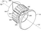
参照图2,定子122还包括多个电枢绕组,示出了其多个端部绕组、或端匝部分236和238。具体地说,定子芯部200分别包括多个外侧和内侧绕组的端匝部分236和238。在示意性实施方式中,多个端匝支承元件240固定扩口部分径向外表面164和168上,从而便于绕组端匝部分236和238的径向和轴向支承。备选地,可以采用任何数量的元件240包括但不局限于不设置。元件240可以由具有包括但不局限于便于与表面164和168以及绕组端匝部分236和238的材料属性形成材料和操作相容以及便于获得与电动机104相关的预定操作参数的那些特性的任何材料制成。Referring to FIG. 2 , the
图14是可以分别用于电动机104的多个示意性电枢槽外绕组和内绕组242和244的横截面示意图。为了观察示出了转子部分140、转子旋转轴线132以及轭部204。图15是可以用于电动机104的定子齿部202与定子封装件中心部分152(在图3中示出)相连的偏斜轴向示意图。为了观察在图15中示出了转子旋转轴线132和扩口封装部分158和160。齿部202分别在槽208内容纳多个电枢槽外绕组和内绕组242和244。绕组242定位在槽208的径向外部。绕组244定位在槽208的径向内部。绕组端匝部分236和238与绕组242和244电连接并从绕组242和244向外轴向延伸并且绕组242和244以及端匝236和238形成一个线圈。在该构造中,一个线圈的径向绕组244在槽208内定位在另一线圈的径向外绕组242的径向内侧。备选地,可以采用任何数量和任何构造的绕组。在示意性实施方式中,绕组242和244以及端匝部分236和238是利用本领域已知的材料、设备和方法制成的导电杆。备选地,绕组242和244以及端匝部分236和238可以是但不局限于导电电缆。在将齿部202封装在轭部204内之前将绕组242和244定位在槽208内便于提高组件的效率并便于减小可能产生的绕组242和244的变形。14 is a schematic cross-sectional view of a plurality of exemplary armature slot outer and
图16是可以用于电动机104(在图2中示出)的多个示意性电枢绕组242和244的横截面轴向示意图。为了观察示出了转子旋转轴线132和封装部分152。齿部202被示出所有的绕组242和244都定位在齿部206与从其中延伸的端匝部分236(和238)之间的槽208内。绕组242和244以及端匝部分236(和238)被示出基本上是透明的并且为了便于观察省去了封装件扩口部分158(和160)(在图15中示出)。FIG. 16 is a cross-sectional axial schematic illustration of a plurality of
图17是可以用于电动机104(在图2中示出)的连接在多个电枢绕组242和244上的多个轭部片段214的横截面轴向示意图。为了观察示出了转子旋转轴线132和封装部分152并省去了封装件扩口部分158(和160)(在图15中示出)。齿部202被示出所有的绕组242和244都定位在齿部206与从其中延伸的端匝部分236(和238)之间的槽208内。齿部202还被示出定位在第一轭片段214内。端匝部分236(和238)从齿部202向外轴向和张开地径向延伸并被示出部分地遮挡下轭片段214。在示意性实施方式中,上轭片段214定位在齿部202以及绕组242与244上并在如上所述的配合表面216处与下轭片段214相连。而且,以这种方式组装轭部204便于减小电枢绕组242和244以及端匝部分236和238的干扰或变形。FIG. 17 is a cross-sectional axial schematic view of a plurality of
图18是可以用于电动机104(在图2中示出)的示意性压力容器105的偏斜轴向示意图。为了观察示出了转子的旋转轴线132。参照图18并结合图2描述压力容器105。压力容器105包括基本上圆柱形的径向外表面246、径向内表面248以及多个外部翼片250。翼片250与外表面246固定连接。压力容器105还包括定位在压力容器105从内表面248向内径向延伸的轴向相对端部的多个基本上环形的端壁251。FIG. 18 is a skewed axial schematic view of an
在示意性实施方式中,翼片250和至少一个端壁251通过包括但不局限于锻造和铸造的方法与压力容器105一体制成。备选地,翼片250和端壁251可以单独制成并通过包括但不局限于焊接和钎焊的方法分别与压力容器的外表面246和内表面相连。翼片250包括便于从电动机104传热的预定轴向和径向尺寸。端壁251包括便于限定环形通道254的预定径向尺寸。开口254的尺寸被设计成便于容纳转子主轴部分142和密封件137。与用于制造压力容器105的材料有关的参数包括但不局限于具有足够的热传导特性以便于热传递,并具有足够的强度和抗腐蚀性以减小压力容器105在操作过程中的变形和腐蚀。可以用于制成压力容器105的材料包括但不局限于IncoloyInconel
在示意性实施方式中,压力容器105基本上是圆柱形的。备选地,压力容器105及其相关的部件可以在获得预定操作参数的前提下具有任何形状和/或构造。同样,在示意性实施方式中,表面246与248之间的径向距离也就是压力容器105的厚度以及压力容器105的制造材料足以有利于承受操作参数例如但不局限于与浸没站100的水深和水体有关的外部操作压力和温度以及输送的流体的属性。In the exemplary embodiment,
图19是可以用于电动机104的示意性压力容器105的轴向示意图。为了清楚地观察示出了封装件中心部分152、齿部202以及轭部204并省去了壁251。一起参照图19和图2进一步描述压力容器105。在示意性实施方式中,压力容器内表面248与轭部外表面220相连以热连通,从而便于从轭部204向压力容器105的热传导。连接表面248与表面220的方法可以包括但不局限于加压的紧配合,其包括但不局限于热压收缩配合和/或液压收缩配合,从而获得预加载的低误差配合。为了进一步连接表面248与表面220,可以通过包括但不局限于焊接、钎焊、粘结剂结合和烧结的方法对在表面248和表面220的配合区域限定的接缝进行密封。压力容器105与轭部204的紧配合便于将齿部202固定在轭部204与封装件150之间。FIG. 19 is an axial schematic view of an
参照图2,每个端壁251的一部分与封装件扩口部分158和160的轴向最外面的部分相连形成基本上环形的定子容室172。容室172基本上将定子芯200与输送流体分隔。容室172可以进一步被描述为多个部分。容室172基本上环形的中心部分260限定在封装件中心部分的径向外表面156与压力容器径向内表面248的一部分之间并封装定子芯部200。外侧端匝部分262限定在中心部分径向外表面156的一部分、扩口部分径向外表面164、端壁252、压力容器径向内表面248的一部分以及芯200的轴向外侧表面之间。部分262封装定子端匝部分236。内侧端匝部分264限定在中心部分径向外表面156的一部分、扩口部分径向外表面168、端壁252、压力容器径向内表面248的一部分以及芯200的轴向内侧表面之间。部分264封装定子端匝部分238。Referring to FIG. 2 , a portion of each
在示意性实施方式中,容室200充有介电流体,例如但不局限于变压器油。介电流体具有包括但不局限于便于热对流和热传导并减小在容室200内可能产生的电弧放射的特性。In the exemplary embodiment,
参照图1和2,在操作中,由压缩机102(在图1中示出)输送的流体还可以被用于方便电动机104的冷却。在向定子122供电并起动电动机104之前,在压力容器105内除定子容室172之外但包括由电动机端盖组件118和端壁252限定的容积在内的容积106在预定增压速度下充有输送流体并获得预定压力,该压力包括但不局限于与进口管路110基本上类似的压力。当容器106的压力变化时,定子封装件172的压力可以同样采用本领域已知的方法和设备得到改变以便于减小容积105与定子容室172之间的压差。Referring to FIGS. 1 and 2 , in operation, fluid delivered by compressor 102 (shown in FIG. 1 ) may also be used to facilitate cooling of
一旦电动机104通电并且转子120旋转,则输送流体的热损耗和流体摩擦损耗会使转子部分140的温度增高。输送流体流动并与转子组件120特别是部分140的热传递便于从转子部分140向其它部件包括但不局限于电动机端盖组件118和封装部分152,158和160传递热量,以随后将热量分别传递到外部环境和容室172内的介电流体。Once the
同样,在电动机104的操作过程中,定子122得到供电,定子端匝部分236和238内的热损耗通常使相关部件的温度增高。部分236和238内的热损耗基本上传导到介电流体。通过同定子端匝部分236和238接触的介电流体与不同部分236和238接触的介电流体之间的介电流体的温差引起对流流体在容室部分262和264内流动。热量随后传递到压力容器105。Also, during operation of the
此外,在电动机104的操作过程中,定子122得到供电,通过电枢绕组242和244(在图14中示出)在定子齿部202内产生的热损耗通过叠层232和234的热传导基本上被收集并引导到压力容器105。Furthermore, during operation of the
如上所述,在操作过程中,压力容器105用于在预定热传递速率下接收来自电动机104的部件的预定热量。围绕压力容器105的环境通常具有比压力容器105内的环境更低的温度。因此,表面246和翼片250通常比表面248更凉并且便于从电动机104向压力容器105之外的环境的热传递。As noted above, during operation, the
在此所述的压缩站便于通过管路输送天然气。更具体地说,压缩站组件包括与超同步电动机相连的压缩装置。超同步电动机便于省去附加部件例如齿轮箱,由此便于使站的基底面更小以及省去相关齿轮箱的维护成本。这种电动机还便于站在更高能量密度和更高速度下操作,由此进一步减小了基底面,以及因具有在更高速度下操作的能力而使效率更高。因此,压缩站的操作效率可以得到提高并且可以降低站的资金和维护成本。The compression stations described herein facilitate the transportation of natural gas by pipeline. More specifically, the compressor station assembly includes a compressor coupled to a supersynchronous motor. Supersynchronous motors facilitate the elimination of additional components such as gearboxes, thereby facilitating a smaller footprint of the station and the associated gearbox maintenance costs. Such motors also facilitate operation at higher energy densities and higher speeds, thereby further reducing footprint, and are more efficient due to the ability to operate at higher speeds. Thus, the operational efficiency of the compression station can be increased and the capital and maintenance costs of the station can be reduced.
在此所述的用于在管路内输送流体的方法和装置便于流体输送站的操作。更具体地说,如上所述的电动机便于形成更坚固的流体输送站的构造。这种电动机的构造还便于提高效率、可靠性并降低维护成本和流体输送站的损耗。The methods and apparatus described herein for transferring fluids in pipelines facilitate the operation of fluid transfer stations. More specifically, an electric motor as described above facilitates the construction of a more robust fluid transfer station. This electric motor configuration also facilitates increased efficiency, reliability, and reduced maintenance costs and losses at the fluid transfer station.
以上详细描述了与流体输送站相关的电动机的示意性实施方式。所述方法、装置和系统并不局限于在此所述的特定实施方式,也不局限于特定示出的电动机和流体输送站。Illustrative embodiments of electric motors associated with fluid transfer stations are described above in detail. The methods, apparatus, and systems are not limited to the specific embodiments described herein, nor to the specific illustrated motors and fluid delivery stations.
尽管已经针对多种特定实施方式描述了本发明,但本领域技术人员将会认识到可以利用处于权利要求精神和范围内的修改方案实施本发明。While the invention has been described in terms of specific embodiments, those skilled in the art will recognize that the invention can be practiced with modification within the spirit and scope of the claims.
部件列表parts list
Claims (6)
Applications Claiming Priority (3)
| Application Number | Priority Date | Filing Date | Title |
|---|---|---|---|
| US11/446029 | 2006-06-02 | ||
| US11/446,029US7579724B2 (en) | 2006-06-02 | 2006-06-02 | Methods and apparatus for using an electrical machine to transport fluids through a pipeline |
| US11/446,029 | 2006-06-02 |
Related Parent Applications (1)
| Application Number | Title | Priority Date | Filing Date |
|---|---|---|---|
| CN2007101064867ADivisionCN101083405B (en) | 2006-06-02 | 2007-06-01 | Method and device for transporting fluid through pipeline by using motor |
Publications (2)
| Publication Number | Publication Date |
|---|---|
| CN102163882A CN102163882A (en) | 2011-08-24 |
| CN102163882Btrue CN102163882B (en) | 2013-01-30 |
Family
ID=38353078
Family Applications (2)
| Application Number | Title | Priority Date | Filing Date |
|---|---|---|---|
| CN2011100648970AActiveCN102163882B (en) | 2006-06-02 | 2007-06-01 | Method and device for transporting fluid through pipeline by using motor |
| CN2007101064867AActiveCN101083405B (en) | 2006-06-02 | 2007-06-01 | Method and device for transporting fluid through pipeline by using motor |
Family Applications After (1)
| Application Number | Title | Priority Date | Filing Date |
|---|---|---|---|
| CN2007101064867AActiveCN101083405B (en) | 2006-06-02 | 2007-06-01 | Method and device for transporting fluid through pipeline by using motor |
Country Status (6)
| Country | Link |
|---|---|
| US (2) | US7579724B2 (en) |
| EP (1) | EP1863152B1 (en) |
| JP (1) | JP5237579B2 (en) |
| CN (2) | CN102163882B (en) |
| AU (1) | AU2007202510B2 (en) |
| NO (1) | NO339144B1 (en) |
Families Citing this family (29)
| Publication number | Priority date | Publication date | Assignee | Title |
|---|---|---|---|---|
| US7508101B2 (en)* | 2006-02-24 | 2009-03-24 | General Electric Company | Methods and apparatus for using an electrical machine to transport fluids through a pipeline |
| US8875380B2 (en)* | 2007-03-08 | 2014-11-04 | General Electric Company | Process of forming an encapsulated magnet assembly |
| US20090058221A1 (en)* | 2007-08-29 | 2009-03-05 | Schlumberger Technology Corporation | System and method for protecting submersible motor winding |
| WO2009137317A1 (en)* | 2008-05-06 | 2009-11-12 | Fmc Technologies, Inc. | Underwater permanent magnet rotor pump |
| US8777596B2 (en)* | 2008-05-06 | 2014-07-15 | Fmc Technologies, Inc. | Flushing system |
| JP2012503971A (en)* | 2008-09-23 | 2012-02-09 | エアロヴァイロンメント インコーポレイテッド | Stator winding heat sink configuration |
| US8084914B2 (en)* | 2009-01-26 | 2011-12-27 | Schlumberger Technology Corporation | Stator coil retention system for unvarnished stators |
| FR2944393B1 (en)* | 2009-04-09 | 2014-10-17 | Converteam Technology Ltd | COIL FOR A ROTATING ELECTRIC MACHINE |
| US8629592B2 (en)* | 2009-06-25 | 2014-01-14 | General Electric Company | Hermetic sealing assembly and electrical device including the same |
| JP5216038B2 (en)* | 2010-03-25 | 2013-06-19 | 株式会社日立製作所 | Rotating motor |
| US20120112571A1 (en)* | 2010-11-09 | 2012-05-10 | General Electric Company | Encapsulated stator assembly |
| EP2689515B1 (en) | 2011-03-23 | 2020-06-24 | Nuovo Pignone S.p.A. | Elastic cone for hermetically sealed stator, corresponding motor and manfacturing method |
| KR20130021206A (en)* | 2011-08-22 | 2013-03-05 | 삼성전기주식회사 | Spindle motor |
| FR2981710B1 (en)* | 2011-10-20 | 2014-07-25 | Mecanique Magnetique Sa | STATOR ELECTROMAGNETIC MACHINE SHIRT FOR CORROSIVE AND NON-HEAT TREATMENT ROOM |
| US9722464B2 (en)* | 2013-03-13 | 2017-08-01 | Honeywell International Inc. | Gas turbine engine actuation systems including high temperature actuators and methods for the manufacture thereof |
| US20140265714A1 (en)* | 2013-03-13 | 2014-09-18 | Remy Technologies, L.L.C. | Transverse flux stator core manufacture |
| US10770953B2 (en) | 2013-04-03 | 2020-09-08 | Lcdrives Corp. | Liquid cooled stator for high efficiency machine |
| WO2015065574A1 (en)* | 2013-10-29 | 2015-05-07 | Exxonmobil Upstream Research Company | High-speed, multi-power submersible pumps and compressor |
| JP2016156282A (en)* | 2015-02-23 | 2016-09-01 | 三菱重工業株式会社 | Compressor system |
| EP3223394A1 (en) | 2016-03-22 | 2017-09-27 | Siemens Aktiengesellschaft | Fluid cooled active part, electric machine and drive system |
| NO347975B1 (en)* | 2016-09-20 | 2024-06-03 | Vetco Gray Scandinavia As | Improved arrangement for pressurizing of fluid |
| US11466696B2 (en)* | 2016-12-28 | 2022-10-11 | Upwing Energy, Inc. | Downhole blower system with bearings and seals |
| WO2018138795A1 (en)* | 2017-01-25 | 2018-08-02 | 株式会社日立産機システム | Motor and compressor that uses same |
| CN111668959B (en)* | 2020-06-24 | 2025-05-09 | 抚顺煤矿电机制造有限责任公司 | A waterproof device for the winding conductive rod of a mining motor |
| JP2023014680A (en)* | 2021-07-19 | 2023-01-31 | アート金属工業株式会社 | Housing, stator unit, motor, and stator unit manufacturing method |
| CN215921885U (en)* | 2021-08-03 | 2022-03-01 | 精进电动科技股份有限公司 | A vehicle electric drive assembly and a new energy vehicle |
| CN113708550B (en)* | 2021-09-14 | 2022-11-15 | 威海西立电子有限公司 | Electric machine |
| EP4462646A1 (en)* | 2023-05-09 | 2024-11-13 | Rolls-Royce Deutschland Ltd & Co KG | Method of manufacturing a stator and a stator for an electrical machine |
| EP4462647A1 (en)* | 2023-05-09 | 2024-11-13 | Rolls-Royce Deutschland Ltd & Co KG | Stator for an electrical machine and method of manufacturing a stator |
Citations (2)
| Publication number | Priority date | Publication date | Assignee | Title |
|---|---|---|---|---|
| US4882514A (en)* | 1988-06-07 | 1989-11-21 | General Electric Company | Submersible sodium pump |
| CN1767320A (en)* | 2004-10-05 | 2006-05-03 | 株式会社东芝 | Rotating electromechanical machines and their armature windings |
Family Cites Families (24)
| Publication number | Priority date | Publication date | Assignee | Title |
|---|---|---|---|---|
| DE1811260B1 (en)* | 1968-11-27 | 1971-08-05 | Witalij Arsenjewiz Obuchow | STAND OF AN ELECTRICAL MACHINE WITH SHEET METAL PACKAGES AXIAL SEPARATED BY VENTILATION DUCTS |
| SU978274A1 (en)* | 1979-10-25 | 1982-11-30 | Научно-Исследовательский Сектор Всесоюзного Ордена Ленина Проектно-Изыскательского И Научно-Исследовательского Института "Гидропроект" Им.С.Я.Жука | Device for fastening stator winding head parts |
| US4968911A (en)* | 1985-11-20 | 1990-11-06 | Allied-Signal Inc. | Clam-shell stator construction for electrical machines |
| US5030877A (en)* | 1985-11-20 | 1991-07-09 | Allied-Signal Inc. | Turbine engine with integral clam shell dynamoelectric machine |
| US4901520A (en)* | 1988-08-12 | 1990-02-20 | Avco Corporation | Gas turbine pressurized cooling system |
| JPH02193546A (en)* | 1989-01-20 | 1990-07-31 | Mayekawa Mfg Co Ltd | Cooling of canned motor |
| US5091666A (en)* | 1990-06-15 | 1992-02-25 | General Electric Company | Stator cooling system for electrical machinery |
| US5205721A (en)* | 1991-02-13 | 1993-04-27 | Nu-Tech Industries, Inc. | Split stator for motor/blood pump |
| JPH07111752A (en)* | 1993-10-08 | 1995-04-25 | Ebara Corp | Magnet pump |
| GB2289992B (en)* | 1994-05-24 | 1998-05-20 | Gec Alsthom Ltd | Improvements in or relating to cooling arrangements in rotating electrical machines |
| DK0764059T3 (en)* | 1994-06-17 | 1999-08-16 | Kaercher Gmbh & Co Alfred | High pressure washer with safety insulation |
| US5627420A (en)* | 1994-12-16 | 1997-05-06 | Westinghouse Electric Corporation | Pump powered by a canned electric motor having a removable stator cartridge |
| US5798593A (en)* | 1996-05-02 | 1998-08-25 | Satcon Technology Corporation | Solid rotor assembly |
| US5990588A (en)* | 1996-12-13 | 1999-11-23 | General Electric Company | Induction motor driven seal-less pump |
| US6191510B1 (en)* | 1997-12-19 | 2001-02-20 | 3M Innovative Properties Company | Internally damped stator, rotor, and transformer and a method of making |
| US6229243B1 (en)* | 1999-04-30 | 2001-05-08 | Precise Power Corporation | Rotor construction for controlled-pole electric machines |
| US6652249B2 (en)* | 1999-12-13 | 2003-11-25 | Parker-Hannifin Corporation | Brushless DC wet motor fuel pump with integral controller |
| US6448685B1 (en) | 2000-09-28 | 2002-09-10 | General Electric Company | Stator core assembly |
| US6445095B1 (en)* | 2001-01-11 | 2002-09-03 | Ford Global Technologies, Inc. | Electric machine with laminated cooling rings |
| JP3696813B2 (en)* | 2001-07-24 | 2005-09-21 | 三菱電機株式会社 | Vehicle alternator stator |
| JP4034077B2 (en)* | 2002-01-30 | 2008-01-16 | カルソニックカンセイ株式会社 | Cand pump |
| DE20308665U1 (en)* | 2003-06-03 | 2004-12-30 | Minebea Co., Ltd. | Internal rotor electric motor |
| US7109626B2 (en)* | 2004-02-06 | 2006-09-19 | Emerson Electric Co. | Compact dynamoelectric machine |
| US7476992B2 (en)* | 2005-05-17 | 2009-01-13 | Parker-Hannifin Corporation | Air-cooled electric motor |
- 2006
- 2006-06-02USUS11/446,029patent/US7579724B2/enactiveActive
- 2007
- 2007-05-25JPJP2007138510Apatent/JP5237579B2/enactiveActive
- 2007-05-26EPEP07109022.9Apatent/EP1863152B1/enactiveActive
- 2007-05-31AUAU2007202510Apatent/AU2007202510B2/ennot_activeCeased
- 2007-06-01CNCN2011100648970Apatent/CN102163882B/enactiveActive
- 2007-06-01NONO20072811Apatent/NO339144B1/ennot_activeIP Right Cessation
- 2007-06-01CNCN2007101064867Apatent/CN101083405B/enactiveActive
- 2009
- 2009-08-21USUS12/545,570patent/US7768173B2/enactiveActive
Patent Citations (2)
| Publication number | Priority date | Publication date | Assignee | Title |
|---|---|---|---|---|
| US4882514A (en)* | 1988-06-07 | 1989-11-21 | General Electric Company | Submersible sodium pump |
| CN1767320A (en)* | 2004-10-05 | 2006-05-03 | 株式会社东芝 | Rotating electromechanical machines and their armature windings |
Non-Patent Citations (1)
| Title |
|---|
| CN特开2003-37951A 2003.02.07 |
Also Published As
| Publication number | Publication date |
|---|---|
| NO339144B1 (en) | 2016-11-14 |
| AU2007202510A1 (en) | 2007-12-20 |
| US20090309431A1 (en) | 2009-12-17 |
| JP2007325491A (en) | 2007-12-13 |
| JP5237579B2 (en) | 2013-07-17 |
| US7768173B2 (en) | 2010-08-03 |
| CN101083405B (en) | 2012-08-29 |
| NO20072811L (en) | 2007-12-03 |
| US20070278879A1 (en) | 2007-12-06 |
| EP1863152A2 (en) | 2007-12-05 |
| AU2007202510B2 (en) | 2011-02-03 |
| CN101083405A (en) | 2007-12-05 |
| US7579724B2 (en) | 2009-08-25 |
| EP1863152B1 (en) | 2020-08-19 |
| EP1863152A3 (en) | 2017-11-01 |
| CN102163882A (en) | 2011-08-24 |
Similar Documents
| Publication | Publication Date | Title |
|---|---|---|
| CN102163882B (en) | Method and device for transporting fluid through pipeline by using motor | |
| JP5594859B2 (en) | Method and apparatus for using an electrical machine to transport fluid through a conduit | |
| US7508101B2 (en) | Methods and apparatus for using an electrical machine to transport fluids through a pipeline | |
| KR102823465B1 (en) | Method of making an axial flux motor water pump and its rotor | |
| US11990815B2 (en) | Canned rotodynamic flow machine for a molten salt nuclear reactor and an active magnetic bearing for use in a flow machine for a molten salt nuclear reactor | |
| CA3114640C (en) | Active and passive refrigeration systems for downhole motors | |
| WO2016177933A1 (en) | An end-shield for an electric machine | |
| DK202070505A1 (en) | A canned rotodynamic flow machine for a molten salt nuclear reactor | |
| US20240339874A1 (en) | Motor with enhanced stator cooling | |
| CN112152353B (en) | Permanent magnet machine | |
| DK202070506A1 (en) | An active magnetic bearing for use in a flow machine for a molten salt nuclear reactor |
Legal Events
| Date | Code | Title | Description |
|---|---|---|---|
| C06 | Publication | ||
| PB01 | Publication | ||
| C10 | Entry into substantive examination | ||
| SE01 | Entry into force of request for substantive examination | ||
| C14 | Grant of patent or utility model | ||
| GR01 | Patent grant | ||
| TR01 | Transfer of patent right | Effective date of registration:20231229 Address after:Swiss Baden Patentee after:GENERAL ELECTRIC CO. LTD. Address before:New York, United States Patentee before:General Electric Co. | |
| TR01 | Transfer of patent right |