CN102163852A - Neutral point clamped non-isolated photovoltaic grid-connected inverter - Google Patents
Neutral point clamped non-isolated photovoltaic grid-connected inverterDownload PDFInfo
- Publication number
- CN102163852A CN102163852ACN2011100615214ACN201110061521ACN102163852ACN 102163852 ACN102163852 ACN 102163852ACN 2011100615214 ACN2011100615214 ACN 2011100615214ACN 201110061521 ACN201110061521 ACN 201110061521ACN 102163852 ACN102163852 ACN 102163852A
- Authority
- CN
- China
- Prior art keywords
- power switch
- branch
- switch tube
- filter
- respectively connected
- Prior art date
- Legal status (The legal status is an assumption and is not a legal conclusion. Google has not performed a legal analysis and makes no representation as to the accuracy of the status listed.)
- Granted
Links
Images


Classifications
- H—ELECTRICITY
- H02—GENERATION; CONVERSION OR DISTRIBUTION OF ELECTRIC POWER
- H02M—APPARATUS FOR CONVERSION BETWEEN AC AND AC, BETWEEN AC AND DC, OR BETWEEN DC AND DC, AND FOR USE WITH MAINS OR SIMILAR POWER SUPPLY SYSTEMS; CONVERSION OF DC OR AC INPUT POWER INTO SURGE OUTPUT POWER; CONTROL OR REGULATION THEREOF
- H02M7/00—Conversion of AC power input into DC power output; Conversion of DC power input into AC power output
- H02M7/42—Conversion of DC power input into AC power output without possibility of reversal
- H02M7/44—Conversion of DC power input into AC power output without possibility of reversal by static converters
- H02M7/48—Conversion of DC power input into AC power output without possibility of reversal by static converters using discharge tubes with control electrode or semiconductor devices with control electrode
- H02M7/53—Conversion of DC power input into AC power output without possibility of reversal by static converters using discharge tubes with control electrode or semiconductor devices with control electrode using devices of a triode or transistor type requiring continuous application of a control signal
- H02M7/537—Conversion of DC power input into AC power output without possibility of reversal by static converters using discharge tubes with control electrode or semiconductor devices with control electrode using devices of a triode or transistor type requiring continuous application of a control signal using semiconductor devices only, e.g. single switched pulse inverters
- H02M7/5387—Conversion of DC power input into AC power output without possibility of reversal by static converters using discharge tubes with control electrode or semiconductor devices with control electrode using devices of a triode or transistor type requiring continuous application of a control signal using semiconductor devices only, e.g. single switched pulse inverters in a bridge configuration
- H02M7/5388—Conversion of DC power input into AC power output without possibility of reversal by static converters using discharge tubes with control electrode or semiconductor devices with control electrode using devices of a triode or transistor type requiring continuous application of a control signal using semiconductor devices only, e.g. single switched pulse inverters in a bridge configuration with asymmetrical configuration of switches
- H—ELECTRICITY
- H02—GENERATION; CONVERSION OR DISTRIBUTION OF ELECTRIC POWER
- H02M—APPARATUS FOR CONVERSION BETWEEN AC AND AC, BETWEEN AC AND DC, OR BETWEEN DC AND DC, AND FOR USE WITH MAINS OR SIMILAR POWER SUPPLY SYSTEMS; CONVERSION OF DC OR AC INPUT POWER INTO SURGE OUTPUT POWER; CONTROL OR REGULATION THEREOF
- H02M1/00—Details of apparatus for conversion
- H02M1/12—Arrangements for reducing harmonics from AC input or output
- H02M1/123—Suppression of common mode voltage or current
- Y—GENERAL TAGGING OF NEW TECHNOLOGICAL DEVELOPMENTS; GENERAL TAGGING OF CROSS-SECTIONAL TECHNOLOGIES SPANNING OVER SEVERAL SECTIONS OF THE IPC; TECHNICAL SUBJECTS COVERED BY FORMER USPC CROSS-REFERENCE ART COLLECTIONS [XRACs] AND DIGESTS
- Y02—TECHNOLOGIES OR APPLICATIONS FOR MITIGATION OR ADAPTATION AGAINST CLIMATE CHANGE
- Y02E—REDUCTION OF GREENHOUSE GAS [GHG] EMISSIONS, RELATED TO ENERGY GENERATION, TRANSMISSION OR DISTRIBUTION
- Y02E10/00—Energy generation through renewable energy sources
- Y02E10/50—Photovoltaic [PV] energy
- Y02E10/56—Power conversion systems, e.g. maximum power point trackers
Landscapes
- Engineering & Computer Science (AREA)
- Power Engineering (AREA)
- Inverter Devices (AREA)
Abstract
Translated fromChinese
Description
Translated fromChinese技术领域technical field
本发明涉及一种中点箝位非隔离光伏并网逆变器,属于电力电子变换器技术领域,尤其涉及光伏并网发电。The invention relates to a neutral-point clamped non-isolated photovoltaic grid-connected inverter, which belongs to the technical field of power electronic converters, and in particular relates to photovoltaic grid-connected power generation.
背景技术Background technique
非隔离型光伏并网逆变器拥有效率高、体积小、重量轻和成本低等绝对优势。但由于光伏电池板对地寄生电容的存在,使得并网逆变器开关器件的开关动作可能产生高频时变电压作用在寄生电容之上,由此产生的漏电流可能超出允许范围。高频漏电流的产生还会带来传导和辐射干扰、进网电流谐波及损耗的增加,甚至危及设备和人员的安全。Non-isolated photovoltaic grid-connected inverters have the absolute advantages of high efficiency, small size, light weight and low cost. However, due to the existence of the parasitic capacitance of the photovoltaic panel to the ground, the switching action of the switching device of the grid-connected inverter may generate a high-frequency time-varying voltage to act on the parasitic capacitance, and the resulting leakage current may exceed the allowable range. The generation of high-frequency leakage current will also bring conduction and radiation interference, increase the harmonics and loss of the network current, and even endanger the safety of equipment and personnel.
单极性SPWM全桥并网逆变器的差模特性优良,如输入直流电压利用率高和滤波电感电流脉动量小等受到广泛关注。但同时产生了开关频率脉动的共模电压(其幅值为输入直流电压),使得在光伏并网应用场合需要加入变压器隔离(低频或高频),但高频脉动的共模电压对变压器的绝缘强度构成威胁,进一步增加了制作成本。双极性SPWM全桥并网逆变器共模电压基本恒定,始终等于光伏电池输入电压的二分之一,几乎不会产生共模漏电流。然而与单极性SPWM相比,双极性SPWM存在明显不足:开关损耗和交流滤波电感损耗均是单极性SPWM的两倍,影响了系统的效率。因此,研究非隔离光伏并网逆变器的目的之一就是如何构成新的续流回路,使得变换器同时具有低漏电流和高变换效率的优良性能。The unipolar SPWM full-bridge grid-connected inverter has excellent differential mode characteristics, such as high utilization rate of input DC voltage and small filter inductor current ripple, which has attracted widespread attention. But at the same time, a common-mode voltage with switching frequency pulsation (its amplitude is the input DC voltage) is generated, which makes it necessary to add transformer isolation (low frequency or high frequency) in photovoltaic grid-connected applications. Dielectric strength poses a threat, further increasing production costs. The common-mode voltage of the bipolar SPWM full-bridge grid-connected inverter is basically constant, which is always equal to half of the input voltage of the photovoltaic cell, and almost no common-mode leakage current is generated. However, compared with unipolar SPWM, bipolar SPWM has obvious disadvantages: the switching loss and AC filter inductance loss are twice that of unipolar SPWM, which affects the efficiency of the system. Therefore, one of the purposes of researching non-isolated photovoltaic grid-connected inverters is how to form a new freewheeling circuit so that the converter has both low leakage current and high conversion efficiency.
专利EP 1369985A2提出在全桥电路的桥臂中点间(交流侧)加入双向可控开关组构造新的续流回路;专利US 7411802B2仅在光伏电池侧正端引入一支高频开关,同样可以实现续流阶段太阳能电池端与电网脱离。但根据全桥电路高频共模等效模型,为了消除单极性SPWM调制产生的高频共模电压,必须使续流阶段的续流回路电位箝位在光伏电池输入电压的一半,这样才能使共模电压完全消除,而并非简单的使光伏电池板与电网脱离。文献“马琳,金新民.无变压器结构光伏并网系统共模漏电流分析,太阳能学报,2009,vol.30(7):Page(s):883-888.”提出一种带直流通路的非隔离并网逆变器拓扑,通过增加两支开关管、两支二极管和两个分压电容,使得续流阶段的续流回路电位箝位在光伏电池输入电压的一半,但其电流通路始终经过四个开关器件,故变换效率较低。Patent EP 1369985A2 proposes to add a bidirectional controllable switch group between the midpoints of the bridge arms (AC side) of the full-bridge circuit to construct a new freewheeling circuit; patent US 7411802B2 only introduces a high-frequency switch at the positive end of the photovoltaic cell side, which can also Realize the disconnection of the solar battery terminal from the grid during the freewheeling phase. However, according to the high-frequency common-mode equivalent model of the full-bridge circuit, in order to eliminate the high-frequency common-mode voltage generated by unipolar SPWM modulation, the potential of the freewheeling circuit in the freewheeling stage must be clamped at half of the input voltage of the photovoltaic cell, so that The common mode voltage is completely eliminated, rather than simply disconnecting the photovoltaic panel from the grid. The literature "Ma Lin, Jin Xinmin. Analysis of Common Mode Leakage Current in Photovoltaic Grid-Connected System with Transformerless Structure, Acta Solar Energy Sinica, 2009, vol.30(7): Page(s): 883-888." In the isolated grid-connected inverter topology, by adding two switching tubes, two diodes and two voltage dividing capacitors, the potential of the freewheeling circuit in the freewheeling stage is clamped at half of the input voltage of the photovoltaic cell, but its current path always passes through Four switching devices, so the conversion efficiency is low.
发明内容Contents of the invention
发明目的:本发明所要解决的技术问题是针对上述背景技术的不足,提供一种中点箝位非隔离光伏并网逆变器。Purpose of the invention: The technical problem to be solved by the present invention is to provide a neutral-point clamped non-isolated photovoltaic grid-connected inverter for the above-mentioned deficiencies in the background technology.
本发明为实现上述发明目的采用如下技术方案:The present invention adopts following technical scheme for realizing above-mentioned purpose of the invention:
一种中点箝位非隔离光伏并网逆变器,其输入端与太阳能电池连接,输出端与电网连接,所述中点箝位非隔离光伏并网逆变器包括输入分压电容支路、中点箝位支路、全桥开关单元以及进网滤波器支路;其中输入分压电容支路、中点箝位支路、全桥开关单元、进网滤波器支路依次连接;A neutral-point clamped non-isolated photovoltaic grid-connected inverter, the input end of which is connected to a solar cell, and the output end is connected to a power grid. The neutral-point clamped non-isolated photovoltaic grid-connected inverter includes an input voltage dividing capacitor branch , a mid-point clamping branch, a full-bridge switch unit, and a grid-feeding filter branch; wherein the input voltage dividing capacitor branch, the mid-point clamping branch, the full-bridge switching unit, and the grid-feeding filter branch are connected in sequence;
输入分压电容支路包括由第一分压电容、第二分压电容;The input voltage dividing capacitor branch includes a first voltage dividing capacitor and a second voltage dividing capacitor;
中点箝位支路包括第七功率开关管、第八功率开关管;The midpoint clamping branch includes a seventh power switch tube and an eighth power switch tube;
全桥开关单元包括第一功率开关管、第二功率开关管、第三功率开关管、第四功率开关管、第五功率开关管、第六功率开关管;The full-bridge switch unit includes a first power switch tube, a second power switch tube, a third power switch tube, a fourth power switch tube, a fifth power switch tube, and a sixth power switch tube;
进网滤波器支路包括第一滤波电感、第二滤波电感、滤波电容;The network inlet filter branch includes a first filter inductance, a second filter inductance, and a filter capacitor;
第一分压电容的正端分别连接太阳能电池正输出端、第一功率开关管的漏极、第四功率开关管的漏极,第一分压电容的负端分别连接第二分压电容的正端、第七功率开关管的发射极、第八功率开关管的集电极,第二分压电容的负端分别连接太阳能电池负输出端、第三功率开关管的源极、第六功率开关管的源极;第一功率开关管的源极分别连接第二功率开关管的集电极、第七功率开关管的集电极;第二功率开关管的发射极分别连接第三功率开关管的漏极、第一滤波电感的一端;第四功率开关管的源极分别连接第五功率开关管的集电极、第二滤波电感的一端;第五功率开关管的发射极分别连接第六功率开关管的漏极、第八功率开关管的发射极;第一滤波电感的另一端分别连接滤波电容的一端、电网的一端,第二滤波电感的另一端分别连接滤波电容的另一端、电网的另一端。The positive terminal of the first voltage dividing capacitor is respectively connected to the positive output terminal of the solar cell, the drain of the first power switch tube, and the drain of the fourth power switch tube, and the negative terminal of the first voltage dividing capacitor is respectively connected to the terminal of the second voltage dividing capacitor. The positive terminal, the emitter of the seventh power switch tube, the collector of the eighth power switch tube, and the negative terminal of the second voltage dividing capacitor are respectively connected to the negative output terminal of the solar cell, the source of the third power switch tube, and the sixth power switch tube. The source of the first power switch tube; the source of the first power switch tube is connected to the collector of the second power switch tube and the collector of the seventh power switch tube; the emitter of the second power switch tube is connected to the drain of the third power switch tube pole, one end of the first filter inductor; the source of the fourth power switch tube is respectively connected to the collector of the fifth power switch tube and one end of the second filter inductor; the emitter of the fifth power switch tube is respectively connected to the sixth power switch tube The drain of the eighth power switch tube and the emitter of the eighth power switch tube; the other end of the first filter inductor is respectively connected to one end of the filter capacitor and one end of the grid, and the other end of the second filter inductor is respectively connected to the other end of the filter capacitor and the other end of the grid .
一种中点箝位非隔离光伏并网逆变器,其输入端与太阳能电池连接,输出端与电网连接,所述中点箝位非隔离光伏并网逆变器包括输入分压电容支路、中点箝位支路、全桥开关单元以及进网滤波器支路;其中输入分压电容支路、中点箝位支路、全桥开关单元、进网滤波器支路依次连接;A neutral-point clamped non-isolated photovoltaic grid-connected inverter, the input end of which is connected to a solar cell, and the output end is connected to a power grid. The neutral-point clamped non-isolated photovoltaic grid-connected inverter includes an input voltage dividing capacitor branch , a mid-point clamping branch, a full-bridge switch unit, and a grid-feeding filter branch; wherein the input voltage dividing capacitor branch, the mid-point clamping branch, the full-bridge switching unit, and the grid-feeding filter branch are connected in sequence;
输入分压电容支路包括由第一分压电容、第二分压电容;The input voltage dividing capacitor branch includes a first voltage dividing capacitor and a second voltage dividing capacitor;
中点箝位支路包括第七功率开关管、第八功率开关管;The midpoint clamping branch includes a seventh power switch tube and an eighth power switch tube;
全桥开关单元包括第一功率开关管、第二功率开关管、第三功率开关管、第四功率开关管、第五功率开关管、第六功率开关管;The full-bridge switch unit includes a first power switch tube, a second power switch tube, a third power switch tube, a fourth power switch tube, a fifth power switch tube, and a sixth power switch tube;
进网滤波器支路包括第一滤波电感、第二滤波电感、滤波电容;The network inlet filter branch includes a first filter inductance, a second filter inductance, and a filter capacitor;
第一分压电容的正端分别连接太阳能电池正输出端、第三功率开关管的漏极、第六功率开关管的漏极,第一分压电容的负端分别连接第二分压电容的正端、第八功率开关管的发射极、第七功率开关管的集电极,第二分压电容的负端分别连接太阳能电池负输出端、第一功率开关管的源极、第四功率开关管的源极;第一功率开关管的漏极分别连接第二功率开关管的发射极、第七功率开关管的发射极;第二功率开关管的集电极分别连接第三功率开关管的源极、第一滤波电感的一端;第四功率开关管的漏极分别连接第五功率开关管的发射极、第二滤波电感的一端;第五功率开关管的集电极分别连接第六功率开关管的源极、第八功率开关管的集电极;第一滤波电感的另一端分别连接滤波电容的一端、电网的一端,第二滤波电感的另一端分别连接滤波电容的另一端、电网的另一端。The positive terminal of the first voltage dividing capacitor is respectively connected to the positive output terminal of the solar cell, the drain of the third power switch tube, and the drain of the sixth power switch tube, and the negative terminal of the first voltage dividing capacitor is connected to the terminal of the second voltage dividing capacitor respectively. The positive terminal, the emitter of the eighth power switch tube, the collector of the seventh power switch tube, and the negative terminal of the second voltage dividing capacitor are respectively connected to the negative output terminal of the solar cell, the source of the first power switch tube, and the fourth power switch tube. The source of the tube; the drain of the first power switch tube is respectively connected to the emitter of the second power switch tube and the emitter of the seventh power switch tube; the collector of the second power switch tube is connected to the source of the third power switch tube pole and one end of the first filter inductor; the drain of the fourth power switch tube is connected to the emitter of the fifth power switch tube and one end of the second filter inductor; the collector of the fifth power switch tube is connected to the sixth power switch tube The source of the eighth power switch tube; the other end of the first filter inductor is connected to one end of the filter capacitor and one end of the grid, and the other end of the second filter inductor is respectively connected to the other end of the filter capacitor and the other end of the grid .
一种中点箝位非隔离光伏并网逆变器,其输入端与太阳能电池连接,输出端与电网连接,所述中点箝位非隔离光伏并网逆变器包括输入分压电容支路、中点箝位支路、全桥开关单元以及进网滤波器支路;其中输入分压电容支路、中点箝位支路、全桥开关单元、进网滤波器支路依次连接;A neutral-point clamped non-isolated photovoltaic grid-connected inverter, the input end of which is connected to a solar cell, and the output end is connected to a power grid. The neutral-point clamped non-isolated photovoltaic grid-connected inverter includes an input voltage dividing capacitor branch , a mid-point clamping branch, a full-bridge switch unit, and a grid-feeding filter branch; wherein the input voltage dividing capacitor branch, the mid-point clamping branch, the full-bridge switching unit, and the grid-feeding filter branch are connected in sequence;
输入分压电容支路包括由第一分压电容、第二分压电容;The input voltage dividing capacitor branch includes a first voltage dividing capacitor and a second voltage dividing capacitor;
中点箝位支路包括第七功率开关管、第八功率开关管;The midpoint clamping branch includes a seventh power switch tube and an eighth power switch tube;
全桥开关单元包括第一功率开关管、第二功率开关管、第三功率开关管、第四功率开关管、第五功率开关管、第六功率开关管;The full-bridge switch unit includes a first power switch tube, a second power switch tube, a third power switch tube, a fourth power switch tube, a fifth power switch tube, and a sixth power switch tube;
进网滤波器支路包括第一滤波电感、第二滤波电感、滤波电容;The network inlet filter branch includes a first filter inductance, a second filter inductance, and a filter capacitor;
第一分压电容的正端分别连接太阳能电池正输出端、第三功率开关管的漏极、第六功率开关管的漏极,第一分压电容的负端分别连接第二分压电容的正端、第七功率开关管的发射极、第八功率开关管的发射极,第二分压电容的负端分别连接第一功率开关管的源极、第四功率开关管的源极;第一功率开关管的漏极分别连接第二功率开关管的发射极、第一滤波电感的一端;第二功率开关管的集电极分别连接第三功率开关管的源极、第八功率开关管的集电极;第四功率开关管的漏极分别连接第五功率开关管的发射极、第二滤波电感的一端;第五功率开关管的集电极分别连接第六功率开关管的源极、第七功率开关管的集电极;第一滤波电感的另一端分别连接滤波电容的一端、电网的一端,第二滤波电感的另一端分别连接滤波电容的另一端、电网的另一端。The positive terminal of the first voltage dividing capacitor is respectively connected to the positive output terminal of the solar cell, the drain of the third power switch tube, and the drain of the sixth power switch tube, and the negative terminal of the first voltage dividing capacitor is connected to the terminal of the second voltage dividing capacitor respectively. The positive terminal, the emitter of the seventh power switch tube, the emitter of the eighth power switch tube, and the negative terminal of the second voltage dividing capacitor are respectively connected to the source of the first power switch tube and the source of the fourth power switch tube; The drain of a power switch tube is respectively connected to the emitter of the second power switch tube and one end of the first filter inductor; the collector of the second power switch tube is connected to the source of the third power switch tube and the end of the eighth power switch tube respectively. collector; the drain of the fourth power switch tube is respectively connected to the emitter of the fifth power switch tube and one end of the second filter inductor; the collector of the fifth power switch tube is connected to the source of the sixth power switch tube, the seventh The collector of the power switch tube; the other end of the first filter inductor is respectively connected to one end of the filter capacitor and one end of the grid, and the other end of the second filter inductor is respectively connected to the other end of the filter capacitor and the other end of the grid.
一种中点箝位非隔离光伏并网逆变器,其输入端与太阳能电池连接,输出端与电网连接,所述中点箝位非隔离光伏并网逆变器包括输入分压电容支路、中点箝位支路、全桥开关单元以及进网滤波器支路;其中输入分压电容支路、中点箝位支路、全桥开关单元、进网滤波器支路依次连接;A neutral-point clamped non-isolated photovoltaic grid-connected inverter, the input end of which is connected to a solar cell, and the output end is connected to a power grid. The neutral-point clamped non-isolated photovoltaic grid-connected inverter includes an input voltage dividing capacitor branch , a mid-point clamping branch, a full-bridge switch unit, and a grid-feeding filter branch; wherein the input voltage dividing capacitor branch, the mid-point clamping branch, the full-bridge switching unit, and the grid-feeding filter branch are connected in sequence;
输入分压电容支路包括由第一分压电容、第二分压电容;The input voltage dividing capacitor branch includes a first voltage dividing capacitor and a second voltage dividing capacitor;
中点箝位支路包括第七功率开关管、第八功率开关管;The midpoint clamping branch includes a seventh power switch tube and an eighth power switch tube;
全桥开关单元包括第一功率开关管、第二功率开关管、第三功率开关管、第四功率开关管、第五功率开关管、第六功率开关管;The full-bridge switch unit includes a first power switch tube, a second power switch tube, a third power switch tube, a fourth power switch tube, a fifth power switch tube, and a sixth power switch tube;
进网滤波器支路包括第一滤波电感、第二滤波电感、滤波电容;The network inlet filter branch includes a first filter inductance, a second filter inductance, and a filter capacitor;
第一分压电容的正端分别连接太阳能电池正输出端、第三功率开关管的漏极、第六功率开关管的漏极,第一分压电容的负端分别连接第七功率开关管的集电极、第八功率开关管的集电极、第二分压电容的正端,第二分压电容的负端分别连接第一功率开关管的源极、第四功率开关管的源极;第一功率开关管的漏极分别连接第二功率开关管的发射极、第七功率开关管的发射极;第二功率开关管的集电极分别连接第三功率开关管的源极、第一滤波电感的一端;第四功率开关管的漏极分别连接第五功率开关管的集电极、第八功率开关管的发射极;第五功率开关管的集电极分别连接第六功率开关管的源极、第二滤波电感的一端;第一滤波电感的另一端分别连接滤波电容的一端、电网的一端,第二滤波电感的另一端分别连接滤波电容的另一端、电网的另一端。The positive terminal of the first voltage dividing capacitor is respectively connected to the positive output terminal of the solar battery, the drain of the third power switch tube, and the drain of the sixth power switch tube, and the negative terminal of the first voltage dividing capacitor is respectively connected to the terminal of the seventh power switch tube. The collector, the collector of the eighth power switch tube, the positive terminal of the second voltage dividing capacitor, and the negative terminal of the second voltage dividing capacitor are respectively connected to the source of the first power switch tube and the source of the fourth power switch tube; The drain of a power switch tube is respectively connected to the emitter of the second power switch tube and the emitter of the seventh power switch tube; the collector of the second power switch tube is connected to the source of the third power switch tube and the first filter inductor One end of the fourth power switch tube; the drain of the fourth power switch tube is connected to the collector of the fifth power switch tube and the emitter of the eighth power switch tube; the collector of the fifth power switch tube is connected to the source of the sixth power switch tube, One end of the second filter inductor; the other end of the first filter inductor is respectively connected to one end of the filter capacitor and one end of the grid, and the other end of the second filter inductor is respectively connected to the other end of the filter capacitor and the other end of the grid.
本发明的特点和技术效果:Features and technical effects of the present invention:
(1)在全桥电路的基础上加入两支功率开关管和分压电容构成箝位支路,实现续流阶段时,续流回路电位为光伏电池电压的一半,从而消除非隔离并网逆变器的漏电流;(1) On the basis of the full bridge circuit, two power switch tubes and a voltage dividing capacitor are added to form a clamping branch. When the freewheeling phase is realized, the freewheeling circuit potential is half of the voltage of the photovoltaic cell, thereby eliminating the non-isolated grid-connected inverter. Transformer leakage current;
(2)其中六支功率开关管的最大电压应力为电池电压的一半,可选用低导通电阻的功率开关管,有利于效率的进一步提高;(2) The maximum voltage stress of the six power switch tubes is half of the battery voltage, and a power switch tube with low on-resistance can be selected, which is conducive to further improvement of efficiency;
(3)同一时刻仅有两个功率开关管高频动作,且所有功率开关管的电压变化率均为电池电压的一半,减小了开关损耗和电磁干扰;(3) Only two power switch tubes operate at high frequency at the same time, and the voltage change rate of all power switch tubes is half of the battery voltage, which reduces switching loss and electromagnetic interference;
附图说明Description of drawings
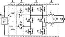
图1是本发明的中点箝位非隔离光伏并网逆变器电路拓扑实施例一;Fig. 1 is a
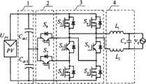
图2是本发明的中点箝位非隔离光伏并网逆变器电路拓扑实施例二;Fig. 2 is the
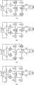
图3是本发明的中点箝位非隔离光伏并网逆变器电路拓扑实施例三;Fig. 3 is the third embodiment of the circuit topology of the neutral point clamped non-isolated photovoltaic grid-connected inverter of the present invention;
图4是本发明的中点箝位非隔离光伏并网逆变器电路拓扑实施例四;Fig. 4 is the fourth embodiment of the circuit topology of the neutral point clamped non-isolated photovoltaic grid-connected inverter of the present invention;
图5是本发明的中点箝位非隔离光伏并网逆变器实施例一的驱动原理波形;Fig. 5 is the driving principle waveform of
图6是本发明的中点箝位非隔离光伏并网逆变器实施例一的各开关模态等效电路图。Fig. 6 is an equivalent circuit diagram of each switching mode of
图中符号说明:Explanation of symbols in the figure:
UPV-光伏电池电压,1-分压电容支路,2-箝位支路,3-全桥开关单元,4-进网滤波器支路,vg-电网,Cdc1、Cdc2-第一、第二分压电容,S1~S8-第一~第八功率开关管,L1、L2-第一、第二滤波电感,Co-滤波电容,ve-调制信号,vst-三角载波信号,vgs1~vgs8-第一~第八功率开关管的驱动电压,t-时间。UPV - Photovoltaic cell voltage, 1 - voltage dividing capacitor branch, 2 - clamping branch, 3 - full bridge switch unit, 4 - grid filter branch, vg - power grid, Cdc1 , Cdc2 - the first 1. The second voltage dividing capacitor, S1 ~ S8 - the first ~ eighth power switch tubes, L1 , L2 - the first and second filter inductors, Co - filter capacitor, ve - modulation signal, vst - triangular carrier signal, vgs1 ~ vgs8 - driving voltage of the first to eighth power switch tubes, t - time.
具体实施方式Detailed ways
为了使本发明实现的技术手段、创作特征、达成目标与功效易于明白了解,下面结合具体图示,进一步阐述本发明。In order to make the technical means, creative features, goals and effects achieved by the present invention easy to understand, the present invention will be further described below in conjunction with specific illustrations.
附图1是中点箝位非隔离光伏并网逆变器电路拓扑实施例一,包括输入分压电容支路1、中点箝位支路2、全桥开关单元3以及进网滤波器支路4;其中输入分压电容支路1、中点箝位支路2、全桥开关单元3、进网滤波器支路4依次连接;Attached drawing 1 is the
输入分压电容支路1包括由第一分压电容Cdc1、第二分压电容Cdc2;The input voltage-dividing
中点箝位支路2包括第七功率开关管S7、第八功率开关管S8;The
全桥开关单元3包括第一功率开关管S1、第二功率开关管S2、第三功率开关管S3、第四功率开关管S4、第五功率开关管S5、第六功率开关管S6;The full-
进网滤波器支路4包括第一滤波电感L1、第二滤波电感L2、滤波电容Co;The
第一分压电容Cdc1的正端分别连接太阳能电池正输出端、第一功率开关管S1的漏极、第四功率开关管S4的漏极,第一分压电容Cdc1的负端分别连接第二分压电容Cdc2的正端、第七功率开关管S7的发射极、第八功率开关管S8的集电极,第二分压电容Cdc2的负端分别连接太阳能电池负输出端、第三功率开关管S3的源极、第六功率开关管S6的源极;第一功率开关管S1的源极分别连接第二功率开关管S2的集电极、第七功率开关管S7的集电极;第二功率开关管S2的发射极分别连接第三功率开关管S3的漏极、第一滤波电感L1的一端;第四功率开关管S4的源极分别连接第五功率开关管S5的集电极、第二滤波电感L2的一端;第五功率开关管S5的发射极分别连接第六功率开关管S6的漏极、第八功率开关管S8的发射极;第一滤波电感L1的另一端分别连接滤波电容Co的一端、电网vg的一端,第二滤波电感L2的另一端分别连接滤波电容Co的另一端、电网vg的另一端。The positive terminal of the first voltage dividing capacitor Cdc1 is respectively connected to the positive output terminal of the solar cell, the drain of the first power switchS1 , the drain of the fourth power switchS4 , and the negative terminal of the first voltage dividing capacitor Cdc1 The positive terminal of the second voltage dividing capacitorCdc2 , the emitter of the seventh power switch tubeS7 , and the collector of the eighth power switch tubeS8 are respectively connected, and the negative terminal of the second voltage dividing capacitorCdc2 is respectively connected to the negative terminal of the solar battery. output terminal, the source of the third power switchS3 , the source of thesixth power switch S6; the source of the first power switchS1 is respectively connected to the collector of the second power switchS2 , the seventh The collector of the power switching tubeS7 ; the emitter of the second power switching tubeS2 is respectively connected to the drain of the third power switching tubeS3 and one end of the first filter inductorL1 ; the source of the fourth power switching tubeS4 The poles are respectively connected to the collector of the fifth power switchS5 and one end of the second filter inductorL2 ; the emitter of the fifth power switchS5 is respectively connected to the drain of the sixth power switchS6 and the eighth power switch The emitter of the tubeS8 ; the other end of the first filter inductorL1 is respectively connected to one end of the filter capacitor Co and one end of the grid vg , and the other end of the second filter inductorL2 is respectively connected to the other end of the filter capacitor Co , The other end of the grid vg .
附图2是中点箝位非隔离光伏并网逆变器电路拓扑实施例二,其电路组成与附图1所示实施例一相同,但电路连接关系为:第一分压电容Cdc1的正端分别连接太阳能电池正输出端、第三功率开关管S3的漏极、第六功率开关管S6的漏极,第一分压电容Cdc1的负端分别连接第二分压电容Cdc2的正端、第八功率开关管S8的发射极、第七功率开关管S7的集电极,第二分压电容Cdc2的负端分别连接太阳能电池负输出端、第一功率开关管S1的源极、第四功率开关管S4的源极;第一功率开关管S1的漏极分别连接第二功率开关管S2的发射极、第七功率开关管S7的发射极;第二功率开关管S2的集电极分别连接第三功率开关管S3的源极、第一滤波电感L1的一端;第四功率开关管S4的漏极分别连接第五功率开关管S5的发射极、第二滤波电感L2的一端;第五功率开关管S5的集电极分别连接第六功率开关管S6的源极、第八功率开关管S8的集电极;第一滤波电感L1的另一端分别连接滤波电容Co的一端、电网vg的一端,第二滤波电感L2的另一端分别连接滤波电容Co的另一端、电网vg的另一端。Attached Figure 2 is the second circuit topology embodiment of the neutral point clamp non-isolated photovoltaic grid-connected inverter, its circuit composition is the same as that of Embodiment 1 shown in Figure1 , but the circuit connection relationship is as follows: The positive terminal is respectively connected to the positive output terminal of the solar cell, the drain of the third power switchS3 , and the drain of the sixth power switchS6 , and the negative terminal of the first voltage dividing capacitor Cdc1 is respectively connected to the second voltage dividing capacitor C The positive terminal ofdc2 , the emitter of the eighth power switch tubeS8 , the collector of the seventh power switch tubeS7 , and the negative terminal of the second voltage dividing capacitor Cdc2 are respectively connected to the negative output terminal of the solar battery and the first power switch tube The source ofS1 and the source of the fourth power switchS4 ; the drain of the first power switchS1 is respectively connected to the emitter of the second power switchS2 and the emitter of the seventh power switchS7 ; The collector of the second power switch tubeS2 is respectively connected to the source of the third power switch tubeS3 and one end of the first filter inductorL1 ; the drain of the fourth power switch tubeS4 is respectively connected to the fifth power switch tube The emitter ofS5 , one end of the second filter inductorL2 ; the collector of the fifth power switchS5 is respectively connected to the source of the sixth power switchS6 and the collector of the eighth power switchS8 ; The other end of the first filter inductorL1 is respectively connected to one end of the filter capacitor Co and one end of the grid vg , and the other end of the second filter inductorL2 is respectively connected to the other end of the filter capacitor Co and the other end of the grid vg .
附图3是中点箝位非隔离光伏并网逆变器电路拓扑实施例三,其电路组成与附图1所示实施例一相同,但电路连接关系为:第一分压电容Cdc1的正端分别连接太阳能电池正输出端、第三功率开关管S3的漏极、第六功率开关管S6的漏极,第一分压电容Cdc1的负端分别连接第二分压电容Cdc2的正端、第七功率开关管S7的发射极、第八功率开关管S8的发射极,第二分压电容Cdc2的负端分别连接第一功率开关管S1的源极、第四功率开关管S4的源极;第一功率开关管S1的漏极分别连接第二功率开关管S2的发射极、第一滤波电感L1的一端;第二功率开关管S2的集电极分别连接第三功率开关管S3的源极、第八功率开关管S8的集电极;第四功率开关管S4的漏极分别连接第五功率开关管S5的发射极、第二滤波电感L2的一端;第五功率开关管S5的集电极分别连接第六功率开关管S6的源极、第七功率开关管S7的集电极;第一滤波电感L1的另一端分别连接滤波电容Co的一端、电网vg的一端,第二滤波电感L2的另一端分别连接滤波电容Co的另一端、电网vg的另一端。Attached Figure 3 is the third circuit topology embodiment of the neutral-point clamped non-isolated photovoltaic grid-connected inverter. Its circuit composition is the same as that of Embodiment 1 shown in Figure1 , but the circuit connection relationship is: The positive terminal is respectively connected to the positive output terminal of the solar cell, the drain of the third power switchS3 , and the drain of the sixth power switchS6 , and the negative terminal of the first voltage dividing capacitor Cdc1 is respectively connected to the second voltage dividing capacitor C The positive end ofdc2 , the emitter of the seventh power switchS7 , the emitter of the eighth power switchS8 , and the negative end of the second voltage dividing capacitor Cdc2 are respectively connected to the source of the first power switchS1 , The source of the fourth power switch tubeS4 ; the drain of the first power switch tubeS1 is respectively connected to the emitter of the second power switch tubeS2 and one end of the first filter inductorL1 ; the second power switch tubeS2 The collector of the third power switchS3 and the collector of theeighth power switch S8 are connected respectively; the drain of the fourth power switchS4 is respectively connected to the emitter of the fifth power switchS5 , One end of the second filter inductorL2 ; the collector of the fifth power switchS5 is respectively connected to the source of the sixth power switchS6 and the collector of the seventh power switchS7 ; the collector of the first filter inductorL1 The other end is respectively connected to one end of the filter capacitor Co and one end of the grid vg , and the other end of the second filter inductorL2 is respectively connected to the other end of the filter capacitor Co and the other end of the grid vg .
附图4是中点箝位非隔离光伏并网逆变器电路拓扑实施例四,其电路组成与附图1所示实施例一相同,但电路连接关系为:第一分压电容Cdc1的正端分别连接太阳能电池正输出端、第三功率开关管S3的漏极、第六功率开关管S6的漏极,第一分压电容Cdc1的负端分别连接第七功率开关管S7的集电极、第八功率开关管S8的集电极、第二分压电容Cdc2的正端,第二分压电容Cdc2的负端分别连接第一功率开关管S1的源极、第四功率开关管S4的源极;第一功率开关管S1的漏极分别连接第二功率开关管S2的发射极、第七功率开关管S7的发射极;第二功率开关管S2的集电极分别连接第三功率开关管S3的源极、第一滤波电感L1的一端;第四功率开关管S4的漏极分别连接第五功率开关管S5的集电极、第八功率开关管S8的发射极;第五功率开关管S5的集电极分别连接第六功率开关管S6的源极、第二滤波电感L2的一端;第一滤波电感L1的另一端分别连接滤波电容Co的一端、电网vg的一端,第二滤波电感L2的另一端分别连接滤波电容Co的另一端、电网vg的另一端。Attached Figure 4 is the fourth embodiment of the circuit topology of a non-isolated photovoltaic grid-connected inverter with neutral point clamping. Its circuit composition is the same as that of Embodiment 1 shown in Figure 1, but the circuit connection relationship is asfollows : The positive terminal is respectively connected to the positive output terminal of the solar cell, the drain of the third power switchS3 , and the drain of the sixth power switchS6 , and the negative terminal of the first voltage dividing capacitor Cdc1 is respectively connected to the seventh power switch S7 , the collector of the eighth power switch tubeS8 , the positive terminal of the second voltage dividing capacitorCdc2 , and the negative terminal of the second voltage dividing capacitorCdc2 are respectively connected to the source of the first power switch tubeS1 , The source of the fourth power switch tubeS4 ; the drain of the first power switch tubeS1 is respectively connected to the emitter of the second power switch tubeS2 and the emitter of the seventh power switch tubeS7 ; the second power switch tube The collector ofS2 is respectively connected to the source of the third power switchS3 and one end of the first filter inductorL1 ; the drain of the fourth power switchS4 is respectively connected to the collector of the fifth power switchS5 , The emitter of the eighth power switch tubeS8 ; the collector of the fifth power switch tubeS5 are respectively connected to the source of the sixth power switch tubeS6 and one end of the second filter inductorL2 ; the collector of the first filter inductorL1 The other end is respectively connected to one end of the filter capacitor Co and one end of the grid vg , and the other end of the second filter inductorL2 is respectively connected to the other end of the filter capacitor Co and the other end of the grid vg .
控制原理和工作过程:Control principle and working process:
下面结合附图5和6说明本发明中点箝位非隔离光伏并网逆变器在具体实施时的调制原理和工作过程。The following describes the modulation principle and working process of the neutral point clamped non-isolated photovoltaic grid-connected inverter of the present invention in conjunction with accompanying drawings 5 and 6 .
附图5是中点箝位非隔离光伏并网逆变器电路拓扑实施例一的驱动原理波形,第一功率开关管S1与第六功率开关管S6驱动信号相同,在进网电流正半周按单极性SPWM方式高频动作,负半周关断;第七功率开关管S7与第八功率开关管S8驱动信号相同,在进网电流正半周与第一功率开关管S1驱动信号互补,并加入死区时间,负半周直通;第三功率开关管S3与第四功率开关管S4驱动信号相同,在进网电流正半周关断,负半周按单极性SPWM方式高频动作;第二功率开关管S2与第五功率开关管S5驱动信号相同,在进网电流正半周直通,负半周与第三功率开关管S3驱动信号互补,并加入死区时间;当调制信号ve大于三角载波信号vst时,驱动信号为高电平,反之为低电平。Accompanying drawing 5 is the waveform of the driving principle of the
附图6是中点箝位非隔离光伏并网逆变器电路拓扑实施例一的各开关模态等效电路图。Accompanying drawing 6 is the equivalent circuit diagram of each switch mode of the
模态1:等效电路如图4(a)所示,第一、第二、第五及第六功率开关管S1、S2、S4、S6导通,其它功率开关管关断,进网电流依次流过第一功率开关管S1、第二功率开关管S2、第一滤波电感L1、电网vg、第二滤波电感L2、第五功率开关管S5、第六功率开关管S6;Mode 1: The equivalent circuit is shown in Figure 4(a), the first, second, fifth and sixth power switches S1 , S2 , S4 , and S6 are turned on, and the other power switches are turned off , the grid current flows sequentially through the first power switch tube S1 , the second power switch tube S2 , the first filter inductor L 1, the grid vg , the second filter inductor L2 , the fifth power switch tube S5 , and the first
模态2:等效电路如图4(b)所示,第二、第五、第七、第八功率开关管S2、S5、S7、S8导通,其它功率开关管关断,由第二、第五功率开关管S2、S5和第七、第八功率开关管S7、S8的体二极管构成续流回路,并由第一、第二分压电容Cdc1、Cdc2的中点将续流回路电位箝位在电池电压UPV的一半;Mode 2: The equivalent circuit is shown in Figure 4(b), the second, fifth, seventh, and eighth power switches S2 , S5 , S7 , and S8 are turned on, and the other power switches are turned off , the freewheeling circuit is formed by the body diodes of the second and fifth power switch tubes S2 and S5 and the seventh and eighth power switch tubes S7 and S8 , and the first and second voltage dividing capacitors Cdc1 , The midpoint of Cdc2 clamps the freewheeling circuit potential at half of the battery voltage UPV ;
模态3:等效电路如图4(c)所示,第三、第四、第七及第八功率开关管S3、S4、S7、S8导通,其它功率开关管关断;第七、第八功率开关管S7、S8虽然导通,但由于其体二极管的阻断作用,没有电流流过,进网电流依次流过第四功率开关管S4、第二滤波电感L2、电网vg、第一滤波电感L1、第三功率开关管S3;Mode 3: The equivalent circuit is shown in Figure 4(c), the third, fourth, seventh and eighth power switches S3 , S4 , S7 , and S8 are turned on, and the other power switches are turned off ; The seventh and eighth power switch tubes S7 and S8 are turned on, but due to the blocking effect of their body diodes, no current flows through, and the incoming current flows through the fourth power switch tube S4 and the second filter tube in turn. Inductor L2 , grid vg , first filter inductance L1 , third power switch tube S3 ;
模态4:等效电路如图4(d)所示,第二、第五、第七、第八功率开关管S2、S5、S7、S8导通,其它功率开关管关断,由第二、第五功率开关管S2、S5的体二极管和第七、第八功率开关管S7、S8构成续流回路,并由第一、第二分压电容Cdc1、Cdc2的中点将续流回路电位箝位在电池电压UPV的一半;Mode 4: The equivalent circuit is shown in Figure 4(d), the second, fifth, seventh, and eighth power switches S2 , S5 , S7 , and S8 are turned on, and the other power switches are turned off , the body diodes of the second and fifth power switch tubes S2 and S5 and the seventh and eighth power switch tubes S7 and S8 form a freewheeling circuit, and the first and second voltage dividing capacitors Cdc1 , The midpoint of Cdc2 clamps the freewheeling circuit potential at half of the battery voltage UPV ;
可见,无论进网电流的方向如何,续流阶段,续流回路电位始终被箝位在电池电压UPV的一半。It can be seen that no matter what the direction of the incoming current is, the potential of the freewheeling circuit is always clamped at half of the battery voltage UPV during the freewheeling phase.
Claims (4)
Translated fromChinesePriority Applications (1)
| Application Number | Priority Date | Filing Date | Title |
|---|---|---|---|
| CN201110061521.4ACN102163852B (en) | 2011-03-15 | 2011-03-15 | A midpoint clamped non-isolated photovoltaic grid-connected inverter |
Applications Claiming Priority (1)
| Application Number | Priority Date | Filing Date | Title |
|---|---|---|---|
| CN201110061521.4ACN102163852B (en) | 2011-03-15 | 2011-03-15 | A midpoint clamped non-isolated photovoltaic grid-connected inverter |
Publications (2)
| Publication Number | Publication Date |
|---|---|
| CN102163852Atrue CN102163852A (en) | 2011-08-24 |
| CN102163852B CN102163852B (en) | 2014-02-26 |
Family
ID=44464896
Family Applications (1)
| Application Number | Title | Priority Date | Filing Date |
|---|---|---|---|
| CN201110061521.4AExpired - Fee RelatedCN102163852B (en) | 2011-03-15 | 2011-03-15 | A midpoint clamped non-isolated photovoltaic grid-connected inverter |
Country Status (1)
| Country | Link |
|---|---|
| CN (1) | CN102163852B (en) |
Cited By (17)
| Publication number | Priority date | Publication date | Assignee | Title |
|---|---|---|---|---|
| CN102361408A (en)* | 2011-10-20 | 2012-02-22 | 东南大学 | Non-isolated photovoltaic grid-connected inverter and switching control time sequence thereof |
| CN102427303A (en)* | 2011-12-29 | 2012-04-25 | 阳光电源股份有限公司 | Single-phase inverter |
| CN102624268A (en)* | 2012-03-27 | 2012-08-01 | 阳光电源股份有限公司 | Inverter and application circuit in three-phase system |
| CN103701355A (en)* | 2013-12-18 | 2014-04-02 | 南京航空航天大学 | Control system of NPC (Neutral Point Clamped) tri-level half-bridge inverter and voltage sharing control method |
| CN104300822A (en)* | 2014-09-26 | 2015-01-21 | 南京邮电大学 | Control method of single-phase non-isolated photovoltaic inverter with freewheeling clamp switch |
| CN104600701A (en)* | 2014-07-01 | 2015-05-06 | 国家电网公司 | Active filter low switching loss type circuit structure and compensating current modulation method |
| CN104967350A (en)* | 2015-07-20 | 2015-10-07 | 安徽大学 | A high-efficiency H7 type single-phase non-isolated grid-connected inverter |
| CN105186914A (en)* | 2015-08-14 | 2015-12-23 | 安徽大学 | Novel H6 single-phase non-isolation grid-connected inverter |
| CN105186912A (en)* | 2015-09-28 | 2015-12-23 | 河海大学 | Two-stage non-isolated full-bridge grid-connected inverter |
| CN105262361A (en)* | 2015-09-28 | 2016-01-20 | 河海大学 | Two-stage non-isolation photovoltaic grid-connected inverter and control method thereof |
| CN105281361A (en)* | 2015-09-25 | 2016-01-27 | 河海大学 | Five-level double-step down grid-connected inverter |
| CN104600701B (en)* | 2014-07-01 | 2016-11-30 | 国家电网公司 | Active filter low switching losses compensates current modulating method |
| CN108347191A (en)* | 2018-03-15 | 2018-07-31 | 国网上海市电力公司 | A kind of single-phase photovoltaic grid-connected inversion topological structure of non-isolation type |
| CN108712098A (en)* | 2018-08-02 | 2018-10-26 | 宝雨控股有限公司 | Three-level inverter and its inverter circuit structure for static passive compensation device |
| CN108964502A (en)* | 2018-09-30 | 2018-12-07 | 华南理工大学 | A kind of single-phase non-isolated active clamp MOSFET inverter |
| CN110649831A (en)* | 2019-05-10 | 2020-01-03 | 阳光电源股份有限公司 | Shutdown wave-sealing control method of multi-level inverter circuit and application device thereof |
| WO2021026876A1 (en)* | 2019-08-15 | 2021-02-18 | Tridonic Gmbh & Co Kg | Driver module and lighting system suitable for use in a humid environment |
Citations (4)
| Publication number | Priority date | Publication date | Assignee | Title |
|---|---|---|---|---|
| EP2051357A1 (en)* | 2007-10-19 | 2009-04-22 | SMA Solar Technology AG | Inverter, in particular for solar panel assemblies |
| CN101814856A (en)* | 2009-11-24 | 2010-08-25 | 南京航空航天大学 | Non-isolated grid-connected inverter and switch control time sequence thereof |
| CN101908831A (en)* | 2009-06-04 | 2010-12-08 | 北京昆兰新能源技术有限公司 | Circuit for converting direct-current voltage into alternating-current voltage |
| CN101951145A (en)* | 2010-09-01 | 2011-01-19 | 天津大学 | Three-level Buck conversion control method of X-shaped symmetrical H bridge and implementation device thereof |
- 2011
- 2011-03-15CNCN201110061521.4Apatent/CN102163852B/ennot_activeExpired - Fee Related
Patent Citations (4)
| Publication number | Priority date | Publication date | Assignee | Title |
|---|---|---|---|---|
| EP2051357A1 (en)* | 2007-10-19 | 2009-04-22 | SMA Solar Technology AG | Inverter, in particular for solar panel assemblies |
| CN101908831A (en)* | 2009-06-04 | 2010-12-08 | 北京昆兰新能源技术有限公司 | Circuit for converting direct-current voltage into alternating-current voltage |
| CN101814856A (en)* | 2009-11-24 | 2010-08-25 | 南京航空航天大学 | Non-isolated grid-connected inverter and switch control time sequence thereof |
| CN101951145A (en)* | 2010-09-01 | 2011-01-19 | 天津大学 | Three-level Buck conversion control method of X-shaped symmetrical H bridge and implementation device thereof |
Cited By (22)
| Publication number | Priority date | Publication date | Assignee | Title |
|---|---|---|---|---|
| CN102361408A (en)* | 2011-10-20 | 2012-02-22 | 东南大学 | Non-isolated photovoltaic grid-connected inverter and switching control time sequence thereof |
| CN102427303A (en)* | 2011-12-29 | 2012-04-25 | 阳光电源股份有限公司 | Single-phase inverter |
| CN102624268A (en)* | 2012-03-27 | 2012-08-01 | 阳光电源股份有限公司 | Inverter and application circuit in three-phase system |
| CN102624268B (en)* | 2012-03-27 | 2014-07-16 | 阳光电源股份有限公司 | Inverter and application circuit in three-phase system |
| CN103701355B (en)* | 2013-12-18 | 2016-04-20 | 南京航空航天大学 | The control system of neutral point clamp type tri-level half-bridge inverter and pressure equalizing control method |
| CN103701355A (en)* | 2013-12-18 | 2014-04-02 | 南京航空航天大学 | Control system of NPC (Neutral Point Clamped) tri-level half-bridge inverter and voltage sharing control method |
| CN104600701A (en)* | 2014-07-01 | 2015-05-06 | 国家电网公司 | Active filter low switching loss type circuit structure and compensating current modulation method |
| CN104600701B (en)* | 2014-07-01 | 2016-11-30 | 国家电网公司 | Active filter low switching losses compensates current modulating method |
| CN104300822A (en)* | 2014-09-26 | 2015-01-21 | 南京邮电大学 | Control method of single-phase non-isolated photovoltaic inverter with freewheeling clamp switch |
| CN104967350A (en)* | 2015-07-20 | 2015-10-07 | 安徽大学 | A high-efficiency H7 type single-phase non-isolated grid-connected inverter |
| CN105186914A (en)* | 2015-08-14 | 2015-12-23 | 安徽大学 | Novel H6 single-phase non-isolation grid-connected inverter |
| CN105281361A (en)* | 2015-09-25 | 2016-01-27 | 河海大学 | Five-level double-step down grid-connected inverter |
| CN105262361A (en)* | 2015-09-28 | 2016-01-20 | 河海大学 | Two-stage non-isolation photovoltaic grid-connected inverter and control method thereof |
| CN105186912A (en)* | 2015-09-28 | 2015-12-23 | 河海大学 | Two-stage non-isolated full-bridge grid-connected inverter |
| CN105262361B (en)* | 2015-09-28 | 2017-11-14 | 河海大学 | A kind of two-stage type non-isolated grid-connected inverter and its control method |
| CN108347191A (en)* | 2018-03-15 | 2018-07-31 | 国网上海市电力公司 | A kind of single-phase photovoltaic grid-connected inversion topological structure of non-isolation type |
| CN108712098A (en)* | 2018-08-02 | 2018-10-26 | 宝雨控股有限公司 | Three-level inverter and its inverter circuit structure for static passive compensation device |
| CN108712098B (en)* | 2018-08-02 | 2024-02-09 | 宝雨控股有限公司 | Three-level inverter for static reactive power compensation device and its inverter circuit structure |
| CN108964502A (en)* | 2018-09-30 | 2018-12-07 | 华南理工大学 | A kind of single-phase non-isolated active clamp MOSFET inverter |
| CN110649831A (en)* | 2019-05-10 | 2020-01-03 | 阳光电源股份有限公司 | Shutdown wave-sealing control method of multi-level inverter circuit and application device thereof |
| US11424694B2 (en) | 2019-05-10 | 2022-08-23 | Sungrow Power Supply Co., Ltd. | Method for controlling shutdown wave blocking of multilevel inverter circuit and application thereof |
| WO2021026876A1 (en)* | 2019-08-15 | 2021-02-18 | Tridonic Gmbh & Co Kg | Driver module and lighting system suitable for use in a humid environment |
Also Published As
| Publication number | Publication date |
|---|---|
| CN102163852B (en) | 2014-02-26 |
Similar Documents
| Publication | Publication Date | Title |
|---|---|---|
| CN102163852B (en) | A midpoint clamped non-isolated photovoltaic grid-connected inverter | |
| CN101814856B (en) | Non-isolated grid-connected inverter and switch control time sequence thereof | |
| CN103051233B (en) | Non-isolated single-phase photovoltaic grid-connected inverter and on-off control timing sequence thereof | |
| CN101980409B (en) | Grid-connected photovoltaic inverter | |
| Cui et al. | A novel single-phase transformerless grid-connected inverter | |
| CN102005954B (en) | Single-phase non-isolated photovoltaic grid-connected inverter and control method | |
| CN103199727B (en) | Zero current switching full-bridge type non-isolated photovoltaic grid-connected inverter | |
| CN205647288U (en) | Non - isolated form photovoltaic grid -connected inverter | |
| CN102005958B (en) | Photovoltaic grid-connected three-level inverter | |
| CN103178739B (en) | Zero-voltage transition full-bridge non-isolated photovoltaic grid-connected inverter | |
| CN103346687A (en) | Single-phase non-isolated photovoltaic grid-connected inverter topological structure and control method thereof | |
| WO2013082858A1 (en) | Single-phase asymmetric full-bridge non-isolated photovoltaic grid-connected inverter | |
| CN104242719B (en) | No switching loss type full-bridge non-isolated photovoltaic grid-connected inverter and switching control sequence | |
| CN102361408A (en) | Non-isolated photovoltaic grid-connected inverter and switching control time sequence thereof | |
| CN103326606B (en) | A kind of one-phase five-level inverter | |
| CN105186912B (en) | A kind of non-isolated full-bridge grid-connected inverter of two-stage type | |
| CN104811071A (en) | Photovoltaic inverter and passive decoupling restraining method based on non-isolated LCL filtering | |
| CN105262361B (en) | A kind of two-stage type non-isolated grid-connected inverter and its control method | |
| CN104467506B (en) | A high-efficiency H-bridge photovoltaic inverter based on voltage and current polarity detection | |
| CN104377982A (en) | Zero-voltage switching Heric type non-isolated photovoltaic grid-connected inverter | |
| CN104410310A (en) | Neutral point clamped H-bridge photovoltaic inverter and method for inhibiting common mode leakage current | |
| CN201536328U (en) | grid-connected inverter | |
| CN102195507A (en) | Transformer-less grid-connected inverting circuit | |
| CN104467501B (en) | Shoot-through-prevention midpoint clamping type single-phase non-isolated photovoltaic inverter topology | |
| CN108110796B (en) | Photovoltaic power generation system with component grounded in polarity |
Legal Events
| Date | Code | Title | Description |
|---|---|---|---|
| C06 | Publication | ||
| PB01 | Publication | ||
| C10 | Entry into substantive examination | ||
| SE01 | Entry into force of request for substantive examination | ||
| C14 | Grant of patent or utility model | ||
| GR01 | Patent grant | ||
| CF01 | Termination of patent right due to non-payment of annual fee | Granted publication date:20140226 Termination date:20200315 | |
| CF01 | Termination of patent right due to non-payment of annual fee |