CN102160906B - Oral Suction Portable Nebulizer - Google Patents
Oral Suction Portable NebulizerDownload PDFInfo
- Publication number
- CN102160906B CN102160906BCN2010105274809ACN201010527480ACN102160906BCN 102160906 BCN102160906 BCN 102160906BCN 2010105274809 ACN2010105274809 ACN 2010105274809ACN 201010527480 ACN201010527480 ACN 201010527480ACN 102160906 BCN102160906 BCN 102160906B
- Authority
- CN
- China
- Prior art keywords
- liquid
- suction nozzle
- liquid storage
- storage box
- imbibition nozzle
- Prior art date
- Legal status (The legal status is an assumption and is not a legal conclusion. Google has not performed a legal analysis and makes no representation as to the accuracy of the status listed.)
- Active
Links
Images


Classifications
- A—HUMAN NECESSITIES
- A61—MEDICAL OR VETERINARY SCIENCE; HYGIENE
- A61M—DEVICES FOR INTRODUCING MEDIA INTO, OR ONTO, THE BODY; DEVICES FOR TRANSDUCING BODY MEDIA OR FOR TAKING MEDIA FROM THE BODY; DEVICES FOR PRODUCING OR ENDING SLEEP OR STUPOR
- A61M15/00—Inhalators
- A61M15/06—Inhaling appliances shaped like cigars, cigarettes or pipes
- A—HUMAN NECESSITIES
- A24—TOBACCO; CIGARS; CIGARETTES; SIMULATED SMOKING DEVICES; SMOKERS' REQUISITES
- A24F—SMOKERS' REQUISITES; MATCH BOXES; SIMULATED SMOKING DEVICES
- A24F40/00—Electrically operated smoking devices; Component parts thereof; Manufacture thereof; Maintenance or testing thereof; Charging means specially adapted therefor
- A24F40/40—Constructional details, e.g. connection of cartridges and battery parts
- A24F40/42—Cartridges or containers for inhalable precursors
- A—HUMAN NECESSITIES
- A24—TOBACCO; CIGARS; CIGARETTES; SIMULATED SMOKING DEVICES; SMOKERS' REQUISITES
- A24F—SMOKERS' REQUISITES; MATCH BOXES; SIMULATED SMOKING DEVICES
- A24F40/00—Electrically operated smoking devices; Component parts thereof; Manufacture thereof; Maintenance or testing thereof; Charging means specially adapted therefor
- A24F40/40—Constructional details, e.g. connection of cartridges and battery parts
- A24F40/44—Wicks
- A—HUMAN NECESSITIES
- A24—TOBACCO; CIGARS; CIGARETTES; SIMULATED SMOKING DEVICES; SMOKERS' REQUISITES
- A24F—SMOKERS' REQUISITES; MATCH BOXES; SIMULATED SMOKING DEVICES
- A24F40/00—Electrically operated smoking devices; Component parts thereof; Manufacture thereof; Maintenance or testing thereof; Charging means specially adapted therefor
- A24F40/50—Control or monitoring
- A24F40/53—Monitoring, e.g. fault detection
- A—HUMAN NECESSITIES
- A61—MEDICAL OR VETERINARY SCIENCE; HYGIENE
- A61M—DEVICES FOR INTRODUCING MEDIA INTO, OR ONTO, THE BODY; DEVICES FOR TRANSDUCING BODY MEDIA OR FOR TAKING MEDIA FROM THE BODY; DEVICES FOR PRODUCING OR ENDING SLEEP OR STUPOR
- A61M11/00—Sprayers or atomisers specially adapted for therapeutic purposes
- A61M11/04—Sprayers or atomisers specially adapted for therapeutic purposes operated by the vapour pressure of the liquid to be sprayed or atomised
- A61M11/041—Sprayers or atomisers specially adapted for therapeutic purposes operated by the vapour pressure of the liquid to be sprayed or atomised using heaters
- A61M11/042—Sprayers or atomisers specially adapted for therapeutic purposes operated by the vapour pressure of the liquid to be sprayed or atomised using heaters electrical
- A—HUMAN NECESSITIES
- A61—MEDICAL OR VETERINARY SCIENCE; HYGIENE
- A61M—DEVICES FOR INTRODUCING MEDIA INTO, OR ONTO, THE BODY; DEVICES FOR TRANSDUCING BODY MEDIA OR FOR TAKING MEDIA FROM THE BODY; DEVICES FOR PRODUCING OR ENDING SLEEP OR STUPOR
- A61M15/00—Inhalators
- A61M15/0065—Inhalators with dosage or measuring devices
- A61M15/0068—Indicating or counting the number of dispensed doses or of remaining doses
- A61M15/0081—Locking means
- A—HUMAN NECESSITIES
- A24—TOBACCO; CIGARS; CIGARETTES; SIMULATED SMOKING DEVICES; SMOKERS' REQUISITES
- A24F—SMOKERS' REQUISITES; MATCH BOXES; SIMULATED SMOKING DEVICES
- A24F40/00—Electrically operated smoking devices; Component parts thereof; Manufacture thereof; Maintenance or testing thereof; Charging means specially adapted therefor
- A24F40/10—Devices using liquid inhalable precursors
- A—HUMAN NECESSITIES
- A61—MEDICAL OR VETERINARY SCIENCE; HYGIENE
- A61M—DEVICES FOR INTRODUCING MEDIA INTO, OR ONTO, THE BODY; DEVICES FOR TRANSDUCING BODY MEDIA OR FOR TAKING MEDIA FROM THE BODY; DEVICES FOR PRODUCING OR ENDING SLEEP OR STUPOR
- A61M11/00—Sprayers or atomisers specially adapted for therapeutic purposes
- A61M11/005—Sprayers or atomisers specially adapted for therapeutic purposes using ultrasonics
- A—HUMAN NECESSITIES
- A61—MEDICAL OR VETERINARY SCIENCE; HYGIENE
- A61M—DEVICES FOR INTRODUCING MEDIA INTO, OR ONTO, THE BODY; DEVICES FOR TRANSDUCING BODY MEDIA OR FOR TAKING MEDIA FROM THE BODY; DEVICES FOR PRODUCING OR ENDING SLEEP OR STUPOR
- A61M2205/00—General characteristics of the apparatus
- A61M2205/27—General characteristics of the apparatus preventing use
- A61M2205/276—General characteristics of the apparatus preventing use preventing unwanted use
- A—HUMAN NECESSITIES
- A61—MEDICAL OR VETERINARY SCIENCE; HYGIENE
- A61M—DEVICES FOR INTRODUCING MEDIA INTO, OR ONTO, THE BODY; DEVICES FOR TRANSDUCING BODY MEDIA OR FOR TAKING MEDIA FROM THE BODY; DEVICES FOR PRODUCING OR ENDING SLEEP OR STUPOR
- A61M2205/00—General characteristics of the apparatus
- A61M2205/36—General characteristics of the apparatus related to heating or cooling
- A61M2205/3653—General characteristics of the apparatus related to heating or cooling by Joule effect, i.e. electric resistance
- A—HUMAN NECESSITIES
- A61—MEDICAL OR VETERINARY SCIENCE; HYGIENE
- A61M—DEVICES FOR INTRODUCING MEDIA INTO, OR ONTO, THE BODY; DEVICES FOR TRANSDUCING BODY MEDIA OR FOR TAKING MEDIA FROM THE BODY; DEVICES FOR PRODUCING OR ENDING SLEEP OR STUPOR
- A61M2205/00—General characteristics of the apparatus
- A61M2205/70—General characteristics of the apparatus with testing or calibration facilities
- A—HUMAN NECESSITIES
- A61—MEDICAL OR VETERINARY SCIENCE; HYGIENE
- A61M—DEVICES FOR INTRODUCING MEDIA INTO, OR ONTO, THE BODY; DEVICES FOR TRANSDUCING BODY MEDIA OR FOR TAKING MEDIA FROM THE BODY; DEVICES FOR PRODUCING OR ENDING SLEEP OR STUPOR
- A61M2205/00—General characteristics of the apparatus
- A61M2205/82—Internal energy supply devices
- A61M2205/8268—Fuel storage cells
Landscapes
- Health & Medical Sciences (AREA)
- Engineering & Computer Science (AREA)
- Life Sciences & Earth Sciences (AREA)
- Biomedical Technology (AREA)
- Heart & Thoracic Surgery (AREA)
- Hematology (AREA)
- Anesthesiology (AREA)
- Animal Behavior & Ethology (AREA)
- General Health & Medical Sciences (AREA)
- Public Health (AREA)
- Veterinary Medicine (AREA)
- Bioinformatics & Cheminformatics (AREA)
- Pulmonology (AREA)
- Biophysics (AREA)
- Special Spraying Apparatus (AREA)
Abstract
Description
Translated fromChinese技术领域technical field
本发明涉及一种雾化装置,具体涉及一种口吸式便携雾化器。The invention relates to an atomizing device, in particular to a mouth-suction portable atomizer.
背景技术Background technique
现在人们的生活及社会活动的加强,人与人之间的交往也越来越重要,而口腔异味等问题另许多人困惑不堪,虽然也有口香糖、润喉片等物品可以解决一时之需,但其废弃物又随之产生新的环境污染,如吃过的口香糖,包装锡板等。Now people's lives and social activities are strengthened, and the communication between people is becoming more and more important, and many people are confused by problems such as bad breath. Although there are also items such as chewing gum and throat lozenges that can solve temporary needs, but Its waste produces new environmental pollution thereupon, as eaten chewing gum, packing tin plate etc.
早期有人提出将药液经过机械装置加热供使用者使用,虽然使用者在使用习惯上易于接受,但由于传统的机械结构性能不稳定,极易损坏,操作烦琐。使使用者造成损失。随着科技的发展,出现了超声雾化器。与机械装置加热实现液体雾化不同的是,基于特定频率下超声波对液体的振荡激发作用,可以产生对应的雾化微滴,从而输送到人体口腔内产生吸烟的感觉。这种雾化方案有些类似与家庭中常见的超声加热器,但超声雾化器存在雾化量偏小,而且能量利用不充分的问题。In the early days, it was proposed to heat the medicinal liquid through a mechanical device for the user to use. Although the user is easy to accept in terms of usage habits, due to the unstable performance of the traditional mechanical structure, it is easily damaged and the operation is cumbersome. cause losses to users. With the development of science and technology, ultrasonic nebulizers appeared. Different from the heating of mechanical devices to achieve liquid atomization, based on the oscillation excitation of liquid by ultrasonic waves at a specific frequency, corresponding atomized droplets can be generated, which can be delivered to the human mouth to produce the feeling of smoking. This atomization scheme is somewhat similar to the common ultrasonic heater in the home, but the ultrasonic atomizer has the problems of small atomization volume and insufficient energy utilization.
目前市场上现有的一些雾化器,存在问题有:第一、药液是注射到吸嘴腔体内的填充层里,由此可见药液不够新鲜,而且药液存储容量小,药液用完了使用者必须往雾化器里滴药液,才能继续使用,这样一来使用者如果想在户外或上班时使用美容,就得带上一瓶药液,才能保证使用。身上带上一瓶而且还要使用者自己滴液。第二、市场现有的雾化器的结构都是螺纹连接,使用者在使用的时候,先要拧好电池才能使用,这样极不方便、雅观、而且还有点不卫生。第三、使用者在使用雾化器时,储存在填充层中的药液不能均匀地到达加热器上,因此导至药液被加热时不能形成直径很小的微滴,大直径的微滴无法伴随人口的负压作用进入到人的口中,大直径的微滴在重力的作用下落到加热器附近无法进行加热。Some existing atomizers currently on the market have the following problems: first, the liquid medicine is injected into the filling layer in the nozzle cavity, so it can be seen that the liquid medicine is not fresh enough, and the storage capacity of the liquid medicine is small. After finishing, the user must drop the liquid medicine in the atomizer before continuing to use it. In this way, if the user wants to use beauty treatment outdoors or at work, he must bring a bottle of liquid medicine to ensure the use. Carry a bottle with you and ask the user to instill it himself. Second, the structures of the existing atomizers in the market are all threaded connections. When users use them, they must first screw the battery in order to use them. This is extremely inconvenient, elegant, and somewhat unhygienic. Third, when the user uses the atomizer, the liquid medicine stored in the filling layer cannot evenly reach the heater, so that when the liquid medicine is heated, it cannot form droplets with a small diameter, and droplets with a large diameter It cannot enter the mouth of a person with the negative pressure of the population, and the large-diameter droplets fall to the vicinity of the heater under the action of gravity and cannot be heated.
发明内容Contents of the invention
本发明的目的在于提供一种口吸式便携雾化器,本发明能将存储的药液均匀地引导到加热装置上,并且使用者能够使用到较为新鲜的药液。The object of the present invention is to provide a mouth-breathing portable nebulizer, which can evenly guide the stored medicinal liquid to the heating device, and the user can use relatively fresh medicinal liquid.
实现本发明目的的技术方案如下:The technical scheme that realizes the object of the present invention is as follows:
口吸式便携雾化器,壳体的一端设置吸嘴,壳体内部设置具有储液空腔的储液盒,该储液盒一端连接一个雾化装置;雾化装置包括雾化组件,雾化组件包括吸液嘴座以及发热装置,所述吸液嘴座一端设有雾化腔,吸液嘴座的另一端设有与雾化腔连通的通气孔,所述发热装置固定在该雾化腔中;Mouth-suction portable nebulizer, one end of the casing is provided with a suction nozzle, and a liquid storage box with a liquid storage cavity is arranged inside the casing, and one end of the liquid storage box is connected to an atomizing device; the atomizing device includes an atomizing component, an atomizing The atomization assembly includes a liquid suction nozzle seat and a heating device. One end of the liquid suction nozzle seat is provided with an atomization chamber, and the other end of the liquid suction nozzle seat is provided with a vent hole communicating with the atomization chamber. The heating device is fixed on the atomization chamber. In the chamber;
雾化装置还包括导液组件,该导液组件包括吸液嘴以及导液绳,吸液嘴的一端插入到储液盒的储液空腔中,吸液嘴与储液盒的接触部位形成液密封,吸液嘴的另一端与吸液嘴座的雾化腔连通,所述导液绳缠绕在发热装置上,导液绳的两个端部被引入到吸液嘴中。The atomization device also includes a liquid guide assembly, which includes a liquid suction nozzle and a liquid guide rope. One end of the liquid suction nozzle is inserted into the liquid storage cavity of the liquid storage box, and the contact part between the liquid suction nozzle and the liquid storage box forms a The other end of the liquid suction nozzle communicates with the atomization chamber of the liquid suction nozzle seat, the liquid guide rope is wound on the heating device, and the two ends of the liquid guide rope are introduced into the liquid suction nozzle.
采用了上述方案,由于本发明的储液盒中无填充物,因此,使用者使用的药液较为新鲜。导液绳的两个端部被引入到吸液嘴中,导液绳不但可以封住储液盒中的药液,使药液在重力的作用下不会顺着吸液嘴流动到雾化腔中,而且在负压作用下还能将储液盒中的药液引导到发热装置上,由于导液绳是以缠绕的方面布置在发热装置上,因此,通过导液绳的作用能使药液均匀地到达发热装置处,使得药液被加热时均能形成直径很小的微滴,而大直径的微滴减少到几乎没有,从而在正常负压作用力的范围内,被吸出的药液均能被加热后形成雾气到达人的口中。With the above solution, since there is no filler in the liquid storage box of the present invention, the medicinal liquid used by the user is relatively fresh. The two ends of the liquid guide rope are introduced into the liquid suction nozzle. The liquid guide rope can not only seal the liquid medicine in the liquid storage box, so that the liquid medicine will not flow along the liquid suction nozzle to atomize under the action of gravity. In the cavity, and under the action of negative pressure, the liquid medicine in the liquid storage box can also be guided to the heating device. Since the liquid guiding rope is arranged on the heating device in a winding way, the action of the liquid guiding rope can make the The medicine liquid evenly reaches the heating device, so that when the medicine liquid is heated, it can form small-diameter droplets, and the large-diameter droplets are reduced to almost nothing, so that within the range of normal negative pressure, the sucked out The liquid medicine can be heated to form mist and reach people's mouth.
另外,通过导液套,当药液在很大的负压作用力下被吸出时,部分药液不会被加热,而伴随着负压气流进行流动,这些药液在流动的过程中由于重力的作用而落至导液套上;或者加热装置温度不高对药液加热不完全,导至形成的雾气中含有过多的大直径的微滴,这些大直径的微滴伴随负压气流流动时,同样也由于重力的作用而落至导液套上,通过导液套可以将这些未被加热的药液进行吸附,药液经导液套以及导液孔到达雾化腔中的加热装置附近,从而被加热装置加热雾化。因此,导液套起到了回收药液,并将回收的药液引导到加热装置处的作用。并且,通过导液套的方式,是全完在药液重力的作用下来完成的,无须人为使用负压作用力将回收的药液进行加热雾化,有省力的好处。In addition, through the liquid guide sleeve, when the liquid medicine is sucked out under a large negative pressure force, part of the liquid medicine will not be heated, but will flow with the negative pressure airflow. or the temperature of the heating device is not high enough to heat the liquid medicine incompletely, resulting in too many large-diameter droplets in the formed mist, and these large-diameter droplets flow with the negative pressure airflow At the same time, it also falls on the liquid guide sleeve due to the action of gravity, and the unheated liquid medicine can be absorbed by the liquid guide sleeve, and the liquid medicine reaches the heating device in the atomization chamber through the liquid guide sleeve and the liquid guide hole. Nearby, it is heated and atomized by the heating device. Therefore, the liquid guide sleeve plays the role of recovering the medicinal liquid and guiding the recovered medicinal liquid to the heating device. Moreover, through the way of the liquid guide sleeve, it is completely completed under the action of the gravity of the liquid medicine, and there is no need to artificially use negative pressure to heat and atomize the recovered liquid medicine, which has the advantage of saving labor.
本发明的另一目的是:为了避免误操作而使按键开关接通,还提供了一种用于雾化器的控制电路和雾化器的控制方法,其技术方案如下:Another object of the present invention is to turn on the button switch in order to avoid misoperation, and also provide a control circuit for the nebulizer and a control method for the nebulizer, the technical scheme of which is as follows:
用于雾化器的控制电路,所述控制电路包括按键开关,该按键开关用于发出接通或断开控制电路的开关信号;A control circuit for the atomizer, the control circuit includes a key switch, and the key switch is used to send a switch signal to turn on or off the control circuit;
以及与按键开关连接的具有锁定作用的单片机,该单片机接收来自于按键开关的信号后,单片机自身进入锁定状态而无输出信号,或者解除锁定;And the single-chip microcomputer with locking function connected with the key switch, after the single-chip microcomputer receives the signal from the key switch, the single-chip microcomputer itself enters the locked state without output signal, or unlocks;
以及与单片机输出端连接的具有信号放大作用的晶体管。And a transistor with a signal amplification function connected with the output terminal of the single-chip microcomputer.
雾化器的控制方法,包括以下步骤:A control method for an atomizer, comprising the following steps:
步骤(1),初始化系统:单片机设置电路进入锁定的时间,以及设置解除电路锁定的时间;Step (1), initializing the system: the single-chip microcomputer sets the time when the circuit enters the lock, and sets the time when the circuit is unlocked;
步骤(2),单片机检测来自于按键开关输出的信号:在锁定状态下的单片机在Q秒接收来自于按键开关的Y次的开关信号,单片机解除锁定;解除锁定后,单片机再次接收来自于按键开关的信号,电路接通单片机向晶体管输出电信号;Step (2), the single-chip microcomputer detects the signal from the key switch output: the single-chip microcomputer in the locked state receives the switch signal from the Y times of the key switch in Q seconds, and the single-chip microcomputer unlocks; after unlocking, the single-chip microcomputer receives again from the key The signal of the switch, the circuit connects the single chip microcomputer to output the electrical signal to the transistor;
步骤(3),晶体管将来自于单片机的信号进行放大后向负载供电,当不再使用时,单片机在P秒内接收的是来自于按键开关的X次的开关信号,单片机进入锁定状态,无输出信号。In step (3), the transistor amplifies the signal from the single-chip microcomputer and then supplies power to the load. When it is no longer in use, the single-chip microcomputer receives X times of switching signals from the key switch within P seconds, and the single-chip microcomputer enters the locked state. output signal.
采用了上述方案,由于在使电路正常导通前,需要经过操作按键开关进行解锁才能使电路正常导通,即使用户进行了误操作,通过单片机对电路的锁定作用,不能使电路导通,因此不会发生意外事故,增加了用户的安全性。The above scheme is adopted. Before the circuit is normally conducted, it needs to be unlocked by operating the key switch to make the circuit normally conduct. No accidents will happen, increasing the safety of users.
附图说明Description of drawings
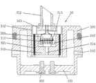
图1为本发明的雾化器的结构示意图;Fig. 1 is the structural representation of atomizer of the present invention;
图2为本发明中雾化装置的结构示意图;Fig. 2 is the structural representation of atomization device among the present invention;
图3为本发明的雾化器与供电装置的装配结构示意图;Fig. 3 is a schematic diagram of the assembly structure of the atomizer and the power supply device of the present invention;
图4为本发明中的控制电路的原理图;Fig. 4 is the schematic diagram of the control circuit in the present invention;
图5为控制电路的流程图;Fig. 5 is the flowchart of control circuit;
附图中,10为壳体,11为吸嘴前盖,12为吸嘴后盖;In the accompanying drawings, 10 is the housing, 11 is the front cover of the suction nozzle, and 12 is the rear cover of the suction nozzle;
20为储液盒,21为盒体,22为盒盖,23为液体隔离膜,24为气流通道;20 is a liquid storage box, 21 is a box body, 22 is a box cover, 23 is a liquid isolation membrane, and 24 is an air flow channel;
30为雾化装置,310为吸液嘴座,311为发热装置,312为套管,313为雾化腔,314为通气孔,315为导液孔;320为导液绳,321为导液套,322为导液管,323为座体;330为雾化器主体,331为接触导体,332为接触导体底座,333为进气孔;30 is an atomizing device, 310 is a liquid suction nozzle seat, 311 is a heating device, 312 is a sleeve, 313 is an atomization chamber, 314 is a vent hole, 315 is a liquid guide hole; 320 is a liquid guide rope, and 321 is a liquid guide Cover, 322 is a catheter, 323 is a base; 330 is the atomizer main body, 331 is a contact conductor, 332 is a contact conductor base, and 333 is an air inlet;
41为外壳,42为电池,43为控制电路,44为接触顶针。41 is a casing, 42 is a battery, 43 is a control circuit, and 44 is a contact thimble.
具体实施方式Detailed ways
下面结合附图和具体实施方式对本发明作进一步说明。The present invention will be further described below in conjunction with the accompanying drawings and specific embodiments.
参照图1至图3,本发明的口吸式便携雾化器。本发明的雾化器与供电装置连接后,对存储的药液进行加热而形成雾气的状态,进而进入到人的口中,药液可以是保健类型的,也可以是用于除去口腔异味的,还可以是对人体有利的其它类型的药液。本发明的雾化器主要由壳体10、储液盒20、雾化装置30三个部分构成,下面通过具体的结构和功能的详细描述对本发明作进一步说明。Referring to Fig. 1 to Fig. 3, the mouth suction portable nebulizer of the present invention. After the atomizer of the present invention is connected to the power supply device, the stored medicinal liquid is heated to form a mist state, and then enters the mouth of the person. The medicinal liquid can be of the health care type, or it can be used to remove bad breath. It can also be other types of medicinal liquids that are beneficial to the human body. The atomizer of the present invention is mainly composed of three parts: a
参照图1,壳体10采用金属材料制成,壳体10纵截面的形状为椭圆形,当然也可以是圆或者矩形等形状。壳体10的一端通过插接的方式固定连接吸嘴,吸嘴由吸嘴前盖11和吸嘴后盖12组成。在吸嘴前盖11和吸嘴后盖12上均设置有通气孔,这些通气孔用于传递人嘴发生的负压作用力,以及使雾化的药液通过通气孔到达人的口中。Referring to FIG. 1 , the
参照图1,具有储液空腔的储液盒20设置在壳体内部,储液盒20是用于存储药液的。储液盒20包括盒体21以及与盒体连接的盒盖22,盒盖上设有供吸液嘴插入的通孔,该通孔处设有可被剌破的液体隔离膜23,液体隔离膜23被吸液嘴剌破后与吸液嘴之间形成液密封。本发明的储液盒的空腔中没有设置任何填充层,药液直接存在空腔中,这样可以避免药液长时间存留在填充层内不新鲜,使用者使用的药液较为新鲜。盒体21的截面形状与壳体的截面形装相同,盒体21与壳体10可以是间隙配合,也可以是过渡配合,但采用过渡配合的方式时,在储液盒21的侧壁面上设置有供气体通过的气流通道24。Referring to FIG. 1 , a
参照图1和图2,储液盒一端连接一个雾化装置30,储液盒中的烟液在负压作用下输出到雾化装置中。雾化装置由雾化组件、导液组件和连接组件三部分组成。Referring to Figures 1 and 2, one end of the liquid storage box is connected to an
参照图2,雾化组件由吸液嘴座310、发热装置311以及套管312组成。吸液嘴座310采用陶瓷材料制成,吸液嘴座310一端设有雾化腔313;吸液嘴座310的另一端设有与雾化腔连通的通气孔314,通气孔314主要是与大气相互连通,以达到吸气时形成负压的目的,通过通气孔与雾化腔连通,在人口吸气产生负压时能轻使地形成负压,使雾化的药液进入到人的口中。吸液嘴座的侧壁上还设有与雾化腔连通的导液孔315,导液孔315在吸液嘴座外侧壁面上的孔口,小于导液孔315在吸液嘴座内侧壁面上的孔口。发热装置311固定在该雾化腔313中,本实施例中,发热装置是通过电流的作用产生热量,因此,发热装置311可以采用铂丝或镍铬合金或含有稀土元素的铁铬铝合金丝制成,也可制成片状体或环状。套管312套在吸液嘴座310的外壁面上,套管312可以吸收吸液嘴座310传来的一部分热量,减小吸液嘴座310上的热量直接传递到外壳上。Referring to FIG. 2 , the atomization assembly consists of a liquid
参照图2,导液组件包括吸液嘴、导液绳320以及导液套321。吸液嘴包括导液管322以及座体323,导液管322的一端与座体连接,导液管的另一端为自由端,该自由端的端面为斜坡面或者三角形,本实施例中,自由端的端面为斜坡面。自由端的端面为斜坡面或三角形,有利于轻松地剌破盒盖22上的液体隔离膜23。吸液嘴与储液盒的接触部位形成液密封,即:导液管的自由端剌破盒盖22上的液体隔离膜23后,插入到盒体21的储液空腔中,由于液体隔离膜23采用橡胶制成,因此,导液管与液体隔离膜23的接触部位形成液密封。吸液嘴的另一端与吸液嘴座的雾化腔连通,由于座体323位于雾化腔313的腔口上方或者与雾化腔313的腔口接触(由于座体的表面积小于雾化腔313的腔口的面积,因此不会堵死雾化腔的腔口),座体即可与吸液嘴座连通。Referring to FIG. 2 , the liquid guiding assembly includes a liquid suction nozzle, a
参照图2,对于导液组件中的导液绳320:导液绳320的中部缠绕在发热装置311上,导液绳的两个端部被引入到吸液嘴中,即导液绳的两个端部被引入到导液管322中。导液绳不但可以封住盒体21中的药液,使药液在重力的作用下不会顺着吸液嘴流动到雾化腔313中,而且在负压作用下还能将盒体21中的药液引导到发热装置上,由于导液绳是以缠绕的方面布置在发热装置上,因此,通过导液绳的作用能使药液均匀地到达发热装置处,使得药液被加热时均能形成直径很小的微滴,而大直径的微滴减少到几乎没有,从而在正常负压作用力的范围内,被吸出的药液均能被加热后形成雾气到达人的口中。Referring to Fig. 2, for the
参照图2,对于导液组件中的导液套321:可以存储大直径悬浮液滴的导液套321套在吸液嘴座的外壁面上,从而导液套321位于吸液嘴座与套管312之间。导液套采用具有多层泡沫的镍网制成。当药液在很大的负压作用力下被吸出时,部分药液不会被加热,而伴随着负压气流进行流动,这些药液在流动的过程中由于重力的作用而落至导液套321上;或者加热装置温度不高对药液加热不完全,导至形成的雾气中含有过多的大直径的微滴,这些大直径的微滴伴随负压气流流动时,同样也由于重力的作用而落至导液套321上,通过导液套可以将这些未被加热的药液进行吸附,药液经导液套以及导液孔315到达雾化腔中的加热装置附近,从而被加热装置加热雾化。因此,导液套321起到了回收药液,并将回收的药液引导到加热装置处的作用。并且,通过导液套321的方式,是全完在药液重力的作用下来完成的,无须人为使用负压作用力将回收的药液进行加热雾化,有省力的好处。Referring to Fig. 2, for the
参照图2,雾化装置30的固定在壳体10另一端的连接组件:该连接组件包括雾化器主体330、通过导线连接发热装置311的接触导体331以及接触导体底座332。雾化器主体330的位于壳体中的一端形成有容纳并保持雾化组件的腔体,套管312及其他雾化组件的零件固定在这个腔体中,套管312与腔体采用过盈的方式进行配合。雾化器主体的侧壁上设有与腔体连通的进气孔333,这个进气孔是用来导通大气的。接触导体底座332固定在雾化器主体的外露于壳体10的另一端,接触导体331固定在接触导体底座332上,接触导体331为两个,分别用于连接电源的正极和负极,每个接触导体上均设有供接触顶针接入的孔。另外,雾化器主体330的外侧面设有一个台阶,雾化器主体330第一是用于支撑雾化组件,第二是用于连接供电装置。Referring to FIG. 2 , the connecting assembly of the
参照图3,雾化器主体330的外露于壳体10的端部连接一个供电装置,该供电装置包括外壳41,以及设置在外壳中的电池42、控制电路43以及接触顶针44。外壳41的一端留有供雾化器主体330插入的空间,雾化器主体330与外壳41形成插拔形式的连接,雾化器主体330插入到外壳41中以后,接触顶针插入到接触导体的孔中。控制电路与电池连接,控制电路的输出端连接接触顶针。Referring to FIG. 3 , the end of the atomizer
参照图4,所述控制电路包括按键开关SW,用于发出接通或断开控制电路的开关信号;与按键开关连接的具有锁定作用的单片机IC1,该单片机接收来自于按键开关的信号后,单片机自身进入锁定状态而无输出信号,或者解除锁定;与单片机输出端连接的具有信号放大作用的晶体管Q1。控制电路还包括一个用于检测电池电压和输出是否短路的检测器Q2,以及用于指示控制电路工作状态的发光二极管Q2,检测器D1及发光二极管D1分别与单片机连接。With reference to Fig. 4, described control circuit comprises key switch SW, is used to send the switch signal that connects or disconnects control circuit; The single-chip microcomputer IC1 with locking effect that is connected with key switch, after this single-chip microcomputer receives the signal from key switch, The single-chip microcomputer itself enters into a locked state without an output signal, or unlocks; and a transistor Q1 with a signal amplification function connected to the output terminal of the single-chip microcomputer. The control circuit also includes a detector Q2 for detecting the battery voltage and whether the output is short-circuited, and a light-emitting diode Q2 for indicating the working state of the control circuit. The detector D1 and the light-emitting diode D1 are connected to the single-chip microcomputer respectively.
20为储液盒,21为盒体,22为盒盖,23为液体隔离膜,24为气流通道;20 is a liquid storage box, 21 is a box body, 22 is a box cover, 23 is a liquid isolation membrane, and 24 is an air flow channel;
30为雾化装置,310为吸液嘴座,311为发热装置,312为套管,313为雾化腔,314为通气孔,315为导液孔;320为导液绳,321为导液套,322为导液管,323为座体;330为雾化器主体,331为接触导体,332为接触导体底座,333为进气孔;30 is an atomizing device, 310 is a liquid suction nozzle seat, 311 is a heating device, 312 is a sleeve, 313 is an atomization chamber, 314 is a vent hole, 315 is a liquid guide hole; 320 is a liquid guide rope, and 321 is a liquid guide Cover, 322 is a catheter, 323 is a base; 330 is the atomizer main body, 331 is a contact conductor, 332 is a contact conductor base, and 333 is an air inlet;
本发明的雾化器的工作过程为(图1中的箭头表示了气流及形成的气溶胶的流动方向):使用者将口吸式便携雾化器与供电装置连接,启动按键开关,解除电路锁定。再次按下按键开关,电流流过接触导体331,使雾化组件中的发热装置311导通而发热。由于负压作用力,使储液盒腔体内的药液通过吸液嘴、导液绳320将药液引导到发热装置311上,在电加热装置311的高温作用下,使药液瞬间雾化。小直径微滴悬浮在负压气流中形成的气溶胶经气流通道24流入吸嘴前盖11,再流入吸嘴后盖12,最终被使用者吸入到口中。当药液使用完之后,可根据使用者的本人的意愿,拔开吸嘴,向储液盒内加药液,用完之后如果使用者不想继续使用这种口味的药液的时候,可以换一个新的储液装置继续使用,旧的一次性雾化器可以丢入可回收的垃圾箱中,回收后可以分解,无环境污染。The working process of the atomizer of the present invention is (the arrow in Fig. 1 indicates the flow direction of the airflow and the formed aerosol): the user connects the mouth-suction portable atomizer with the power supply device, activates the key switch, and releases the circuit locking. Press the key switch again, the current flows through the
参照图4和图5,本发明还提供一种专利用于雾化器的控制电路,所述控制电路包括按键开关SW,用于发出接通或断开控制电路的开关信号;与按键开关连接的具有锁定作用的单片机IC1,该单片机接收来自于按键开关的信号后,单片机自身进入锁定状态而无输出信号,或者解除锁定;与单片机输出端连接的具有信号放大作用的晶体管Q1。控制电路还包括一个用于检测电池电压和输出是否短路的检测器Q2,以及用于指示控制电路工作状态的发光二极管Q2,检测器D1及发光二极管D1分别与单片机连接。Referring to Fig. 4 and Fig. 5, the present invention also provides a patented control circuit for an atomizer, the control circuit includes a key switch SW, which is used to send a switch signal to turn on or off the control circuit; it is connected to the key switch Single-chip microcomputer IC1 with locking function, after the single-chip microcomputer receives the signal from the key switch, the single-chip microcomputer itself enters the locked state without output signal, or unlocks; the transistor Q1 with signal amplification function connected with the output terminal of the single-chip microcomputer. The control circuit also includes a detector Q2 for detecting the battery voltage and whether the output is short-circuited, and a light-emitting diode Q2 for indicating the working state of the control circuit. The detector D1 and the light-emitting diode D1 are connected to the single-chip microcomputer respectively.
本发明还提供了以下两种实施方式的雾化器的控制方法,这两种控制方法主要是防止使用者在日常生活中会无意中碰到开关按键,从而使雾化器开始工作。The present invention also provides the following two control methods of the nebulizer in the following two implementations. These two control methods are mainly to prevent the user from accidentally touching the switch button in daily life, so that the nebulizer starts to work.
实施方式一:Implementation mode one:
包括以下步骤:Include the following steps:
步骤1,初始化系统:单片机设置电路进入锁定的时间,以及设置解除电路锁定的时间;
步骤2,单片机检测来自于按键开关输出的信号:在锁定状态下的单片机在1.5秒内接收来自于按键开关的5次的开关信号,单片机解除锁定。由于锁定和解锁均是在1.5秒内接通按键开关5次,因此,如果用户因为误操作使开关接通1次或者两次,单片机则不会解锁。并且由于时间短,由于误操作而在1.5秒内接通按键开关5次的这种情况不会有,因此,这种设置比较保险。
解除锁定后,单片机再次接收来自于按键开关的信号,电路接通单片机向晶体管输出电信号。After unlocking, the single-chip microcomputer receives the signal from the key switch again, and the circuit is connected to the single-chip microcomputer to output an electrical signal to the transistor.
步骤20,检测电路是否接通,即单片机判断其第2号引脚上的电平是否为低电平。
步骤21,如果步骤20检测结果为是,则单片机将获取的电池的电压输出到检测器,通过检测器Q2判断电池电压是否低于3.3V,并将判断结果输送到单片机;
步骤210,如果步骤21连续三续的判断结果均为是,则单片机进入低压保护状态,同时单片机控制发光二极管闪灯40次,频率为2Hz;
步骤22,如果步骤21的判断结果为否,则通过检测器Q2判电路是否短路,并将判断结果输送到单片机;
步骤220,如果步骤22的判断结果为是,单片机则进入短路保护状态,同时控制发光二极管闪灯3次,频率为3Hz;
如果步骤22的判断结果为否,单片机输出信号到发光二极管,使发光二极管逐渐增亮,0.6秒内达到最亮,同时单片机的第5号引脚变为低电平,单片机IC1向晶体管Q1输出信号;If the judgment result of
步骤3,晶体管Q1将来自于单片机的信号进行放大后向负载供电。如果无需使用,则使单片机在1.5秒内接收的是来自于按键开关的5次的开关信号,单片机进入锁定状态,无输出信号。电路锁定后,即可避免因误操作使电路立即接通,因此雾化器不会因为误操作而工作,避免烫伤使用者。若继续使用,则进入步骤4。In
步骤4,在执行步骤3的过程中,单片机IC1时刻检测按键开关SW是否断开;
步骤41,如果步骤4的检测结果为否,则单片机检测电路是否连续导通10秒;如果检测结果为否,则返回步骤4继续检测;
步骤42,如果步骤41的检测结果为是,则控制发光二极管闪灯10次,闪灯结束后进入待机状态;
步骤43,如果步骤4的检测结果为是,则单片机无信号输出到晶体管Q1,晶体管Q1关闭进入待机状态。进入待机状态后可以选择接通按键开关SW继续使电路导通,如果不使用,则在1.5秒内使按键开关连续接通5次,使电路进入锁定状态。In
步骤5,单片机检测第5号引脚是否有电流输入,如果有电流输入,则说明外部电源向电池进行充电,这时单片机的第5号引脚输出信号使晶体管Q1导通,给电池充电,每6秒种检测一次是否有电流输入,一直检测到没有电流流入即可进入待机状态,或者返回步骤20。
实施方式二:Implementation mode two:
这种实施方式在解除电路锁定和锁定电路与上面一种实施方式有所区别外,其余方式与上面的实施方式完全相同。This implementation mode is completely the same as the above implementation mode except that the unlocking circuit lock and the locking circuit are different from the above one implementation mode.
单片机检测来自于按键开关输出的信号:在锁定状态下的单片机在4秒接收来自于按键开关输出的第一连续信号,单片机解除锁定,解除锁定后,单片机再次接收来自于按键开关的信号,电路接通单片机向晶体管输出电信号。晶体管将来自于单片机的信号进行放大后输出到负载。若单片机在8秒接收的是来自于按键开关输出的第二连续信号,单片机进入锁定状态,无输出信号;即长按按键开关8秒,使其在该时间内连续输出开关闭合的信号到单片机,单片机即可做出锁定电路的决定。The single-chip microcomputer detects the signal from the key switch output: the single-chip microcomputer in the locked state receives the first continuous signal from the key switch output in 4 seconds, and the single-chip microcomputer is unlocked. After unlocking, the single-chip microcomputer receives the signal from the key switch again, and the circuit Turn on the microcontroller to output electrical signals to the transistor. The transistor amplifies the signal from the microcontroller and outputs it to the load. If the MCU receives the second continuous signal from the key switch output in 8 seconds, the MCU enters the locked state and has no output signal; that is, press and hold the key switch for 8 seconds to continuously output the signal of the switch closing to the MCU within this time , the microcontroller can make a decision to lock the circuit.
Claims (8)
Priority Applications (7)
| Application Number | Priority Date | Filing Date | Title |
|---|---|---|---|
| CN2010105274809ACN102160906B (en) | 2010-11-01 | 2010-11-01 | Oral Suction Portable Nebulizer |
| ES11837468.5TES2555410T3 (en) | 2010-11-01 | 2011-07-09 | Portable atomizer of oral aspiration type and control method |
| PL11837468TPL2489391T3 (en) | 2010-11-01 | 2011-07-09 | Oral-suction type portable atomizer and control method thereof |
| EP11837468.5AEP2489391B1 (en) | 2010-11-01 | 2011-07-09 | Oral-suction type portable atomizer and control method thereof |
| PCT/CN2011/077010WO2012058941A1 (en) | 2010-11-01 | 2011-07-09 | Oral-suction type portable atomizer and control method thereof |
| RU2012124102/14ARU2506958C1 (en) | 2010-11-01 | 2011-07-09 | Portable suction spray tube |
| US13/424,712US9132248B2 (en) | 2010-11-01 | 2012-03-20 | Suction-type portable atomizer |
Applications Claiming Priority (1)
| Application Number | Priority Date | Filing Date | Title |
|---|---|---|---|
| CN2010105274809ACN102160906B (en) | 2010-11-01 | 2010-11-01 | Oral Suction Portable Nebulizer |
Related Child Applications (1)
| Application Number | Title | Priority Date | Filing Date |
|---|---|---|---|
| CN201210142180.8ADivisionCN102727969B (en) | 2010-11-01 | 2010-11-01 | Control method for atomizers |
Publications (2)
| Publication Number | Publication Date |
|---|---|
| CN102160906A CN102160906A (en) | 2011-08-24 |
| CN102160906Btrue CN102160906B (en) | 2012-08-08 |
Family
ID=44462528
Family Applications (1)
| Application Number | Title | Priority Date | Filing Date |
|---|---|---|---|
| CN2010105274809AActiveCN102160906B (en) | 2010-11-01 | 2010-11-01 | Oral Suction Portable Nebulizer |
Country Status (7)
| Country | Link |
|---|---|
| US (1) | US9132248B2 (en) |
| EP (1) | EP2489391B1 (en) |
| CN (1) | CN102160906B (en) |
| ES (1) | ES2555410T3 (en) |
| PL (1) | PL2489391T3 (en) |
| RU (1) | RU2506958C1 (en) |
| WO (1) | WO2012058941A1 (en) |
Cited By (2)
| Publication number | Priority date | Publication date | Assignee | Title |
|---|---|---|---|---|
| CN111068151A (en)* | 2019-12-24 | 2020-04-28 | 东南大学 | A novel medical device for treating respiratory diseases and method of use |
| TWI889509B (en)* | 2014-02-06 | 2025-07-01 | 美商尤爾實驗室有限公司 | A vaporization device for generating an inhalable aerosol |
Families Citing this family (213)
| Publication number | Priority date | Publication date | Assignee | Title |
|---|---|---|---|---|
| US20160345631A1 (en) | 2005-07-19 | 2016-12-01 | James Monsees | Portable devices for generating an inhalable vapor |
| US9095175B2 (en) | 2010-05-15 | 2015-08-04 | R. J. Reynolds Tobacco Company | Data logging personal vaporizing inhaler |
| US11344683B2 (en) | 2010-05-15 | 2022-05-31 | Rai Strategic Holdings, Inc. | Vaporizer related systems, methods, and apparatus |
| US9861772B2 (en) | 2010-05-15 | 2018-01-09 | Rai Strategic Holdings, Inc. | Personal vaporizing inhaler cartridge |
| US9259035B2 (en) | 2010-05-15 | 2016-02-16 | R. J. Reynolds Tobacco Company | Solderless personal vaporizing inhaler |
| US9743691B2 (en) | 2010-05-15 | 2017-08-29 | Rai Strategic Holdings, Inc. | Vaporizer configuration, control, and reporting |
| US9999250B2 (en) | 2010-05-15 | 2018-06-19 | Rai Strategic Holdings, Inc. | Vaporizer related systems, methods, and apparatus |
| US10159278B2 (en) | 2010-05-15 | 2018-12-25 | Rai Strategic Holdings, Inc. | Assembly directed airflow |
| US10136672B2 (en) | 2010-05-15 | 2018-11-27 | Rai Strategic Holdings, Inc. | Solderless directly written heating elements |
| US8757147B2 (en) | 2010-05-15 | 2014-06-24 | Minusa Holdings Llc | Personal vaporizing inhaler with internal light source |
| CN103687503A (en) | 2011-04-12 | 2014-03-26 | 罗伯特·列维兹 | Battery connector for e-cigarettes with side air intakes |
| US8528569B1 (en) | 2011-06-28 | 2013-09-10 | Kyle D. Newton | Electronic cigarette with liquid reservoir |
| US9078473B2 (en) | 2011-08-09 | 2015-07-14 | R.J. Reynolds Tobacco Company | Smoking articles and use thereof for yielding inhalation materials |
| CN102499488B (en)* | 2011-09-28 | 2014-03-12 | 卓尔悦(常州)电子科技有限公司 | Electronic cigarette |
| US8820330B2 (en) | 2011-10-28 | 2014-09-02 | Evolv, Llc | Electronic vaporizer that simulates smoking with power control |
| CN202385728U (en) | 2011-11-25 | 2012-08-22 | 周学武 | Electronic cigarette with built-in atomizer |
| KR102166921B1 (en)* | 2011-12-08 | 2020-10-19 | 필립모리스 프로덕츠 에스.에이. | An aerosol generating device with adjustable airflow |
| GB2500957A (en)* | 2011-12-23 | 2013-10-09 | Qiuming Liu | Electronic cigarette suction nozzle |
| AR089607A1 (en)* | 2012-01-03 | 2014-09-03 | Philip Morris Products Sa | ENERGY SUPPLY SYSTEM FOR A PORTABLE AEROSOL GENERATOR DEVICE |
| US9854839B2 (en) | 2012-01-31 | 2018-01-02 | Altria Client Services Llc | Electronic vaping device and method |
| US9289014B2 (en) | 2012-02-22 | 2016-03-22 | Altria Client Services Llc | Electronic smoking article and improved heater element |
| EP2817051B1 (en) | 2012-02-22 | 2017-07-26 | Altria Client Services LLC | Electronic smoking article |
| CN202618275U (en)* | 2012-04-01 | 2012-12-26 | 惠州市吉瑞科技有限公司 | Electronic cigarette and suction nozzle thereof |
| JP5978453B2 (en)* | 2012-04-01 | 2016-08-24 | 恵州市吉瑞科技有限公司深▲せん▼分公司 | Atomization device and electronic cigarette |
| RU2597540C2 (en)* | 2012-04-18 | 2016-09-10 | Фонтем Холдингз 1 Б.В. | Electronic cigarette |
| KR101802616B1 (en)* | 2012-07-09 | 2017-11-28 | 킴르 하이테크 인코퍼레이티드 | Electronic cigarette |
| US8881737B2 (en) | 2012-09-04 | 2014-11-11 | R.J. Reynolds Tobacco Company | Electronic smoking article comprising one or more microheaters |
| US8910639B2 (en)* | 2012-09-05 | 2014-12-16 | R. J. Reynolds Tobacco Company | Single-use connector and cartridge for a smoking article and related method |
| DE102012108477A1 (en)* | 2012-09-11 | 2014-03-13 | SNOKE GmbH & Co. KG | Mouthpiece closure for a mouthpiece of an electric cigarette |
| US10117460B2 (en) | 2012-10-08 | 2018-11-06 | Rai Strategic Holdings, Inc. | Electronic smoking article and associated method |
| US20140123989A1 (en)* | 2012-11-05 | 2014-05-08 | The Safe Cig, Llc | Device and method for vaporizing a fluid |
| CN102940313B (en) | 2012-11-13 | 2015-04-01 | 卓尔悦(常州)电子科技有限公司 | Intelligent controller and intelligent control method for electronic cigarette |
| US10034988B2 (en) | 2012-11-28 | 2018-07-31 | Fontem Holdings I B.V. | Methods and devices for compound delivery |
| CA2890204C (en)* | 2012-11-28 | 2022-04-05 | E-Nicotine Technology, Inc. | Methods and devices for compound delivery |
| USD695449S1 (en) | 2013-01-14 | 2013-12-10 | Altria Client Services Inc. | Electronic smoking article |
| USD841231S1 (en) | 2013-01-14 | 2019-02-19 | Altria Client Services, Llc | Electronic vaping device mouthpiece |
| USD691766S1 (en) | 2013-01-14 | 2013-10-15 | Altria Client Services Inc. | Mouthpiece of a smoking article |
| USD849993S1 (en) | 2013-01-14 | 2019-05-28 | Altria Client Services | Electronic smoking article |
| USD691765S1 (en) | 2013-01-14 | 2013-10-15 | Altria Client Services Inc. | Electronic smoking article |
| CN203103593U (en)* | 2013-02-04 | 2013-07-31 | 深圳市博格科技有限公司 | Electronic cigarette quick connector |
| WO2014127446A1 (en)* | 2013-02-25 | 2014-08-28 | 9208-8699 Québec Inc. | Handheld electronic vaporization device |
| US10031183B2 (en) | 2013-03-07 | 2018-07-24 | Rai Strategic Holdings, Inc. | Spent cartridge detection method and system for an electronic smoking article |
| US9220302B2 (en) | 2013-03-15 | 2015-12-29 | R.J. Reynolds Tobacco Company | Cartridge for an aerosol delivery device and method for assembling a cartridge for a smoking article |
| US20180035721A1 (en)* | 2013-03-15 | 2018-02-08 | Healthier Choices Management Corp | Electronic cigarette |
| US10279934B2 (en) | 2013-03-15 | 2019-05-07 | Juul Labs, Inc. | Fillable vaporizer cartridge and method of filling |
| US11064732B2 (en)* | 2013-03-15 | 2021-07-20 | Healthier Choices Management Corp. | Electronic vaporizer cartridge with encased heat source |
| US9609893B2 (en) | 2013-03-15 | 2017-04-04 | Rai Strategic Holdings, Inc. | Cartridge and control body of an aerosol delivery device including anti-rotation mechanism and related method |
| ITSO20130002A1 (en)* | 2013-03-19 | 2014-09-20 | Raffaele Pettinato | ANTI-LOAD SECURITY SYSTEM FOR A DISPOSABLE MOUTHPIECE |
| US9901119B2 (en)* | 2013-03-29 | 2018-02-27 | Huizhou Kimree Technology Co., Ltd., Shenzhen Branch | Electronic cigarette |
| EA201591944A1 (en)* | 2013-04-10 | 2016-04-29 | Сино Бизнес Лимитед | ELECTRONIC COOKING DEVICE-REPLACEMENT |
| ITBO20130157A1 (en)* | 2013-04-10 | 2014-10-11 | Sino Business Ltd | SMOKE REPLACEMENT ELECTRONIC DEVICE |
| JP6125716B2 (en)* | 2013-04-11 | 2017-05-10 | フイジョウ キムリー テクノロジー シーオー.、エルティーディー.シェンジェン ブランチ | Electronic Cigarette |
| ITBG20130010A1 (en)* | 2013-04-15 | 2014-10-16 | Castelberg Technologies S R L | ELECTRONIC CIGARETTE WITH FLAVORED TABLET AND ITS PRODUCTION METHOD |
| PL2810570T3 (en)* | 2013-06-03 | 2019-06-28 | Fontem Holdings 1 B.V. | System with electronic smoking device and capsule |
| ITMI20131118A1 (en)* | 2013-07-04 | 2015-01-05 | Massimiliano Luciani | IMPROVED SECURITY ELECTRONIC CIGARETTE |
| EP3003075B1 (en)* | 2013-06-03 | 2020-01-08 | Old Navigators Limited | Kit for inhaling vaporized substances |
| WO2014194449A1 (en)* | 2013-06-03 | 2014-12-11 | 吉瑞高新科技股份有限公司 | Electronic cigarette sealing sleeve, electronic cigarette suction stem, and electronic cigarette |
| ITPD20130164A1 (en)* | 2013-06-10 | 2014-12-11 | Cappello Antonio | DISPOSABLE LIQUID RECHARGING SYSTEM FOR ELECTRONIC CIGARETTE |
| ITMO20130192A1 (en)* | 2013-06-28 | 2014-12-29 | Damco S R L | KIT FOR ELECTRONIC CIGARETTES |
| CN203446530U (en)* | 2013-07-17 | 2014-02-26 | 李建伟 | Separated electronic cigarette atomization device |
| US9848645B2 (en) | 2013-07-24 | 2017-12-26 | Sis Resources Ltd. | Cartomizer structure for automated assembly |
| EP2835063B1 (en) | 2013-08-06 | 2019-04-10 | Fontem Holdings 1 B.V. | Electronic smoking device and process of manufacturing thereof |
| US10194693B2 (en) | 2013-09-20 | 2019-02-05 | Fontem Holdings 1 B.V. | Aerosol generating device |
| EP3222159B1 (en) | 2013-09-30 | 2020-06-17 | Japan Tobacco Inc. | Non-burning type flavor inhaler |
| BR302014001648S1 (en) | 2013-10-14 | 2015-06-09 | Altria Client Services Inc | Smoke Applied Configuration |
| SG11201601985VA (en) | 2013-10-29 | 2016-04-28 | British American Tobacco Co | Apparatus for heating smokable material |
| US10292424B2 (en) | 2013-10-31 | 2019-05-21 | Rai Strategic Holdings, Inc. | Aerosol delivery device including a pressure-based aerosol delivery mechanism |
| US10039321B2 (en)* | 2013-11-12 | 2018-08-07 | Vmr Products Llc | Vaporizer |
| JP2016539773A (en)* | 2013-11-28 | 2016-12-22 | エイチケー トライアングル カンパニー リミテッド | Atomizer for electronic cigarette |
| PL2885986T3 (en)* | 2013-12-18 | 2018-03-30 | Fontem Holdings 1 B.V. | Capsule for use with an electronic smoking device |
| US10159282B2 (en) | 2013-12-23 | 2018-12-25 | Juul Labs, Inc. | Cartridge for use with a vaporizer device |
| US20160366947A1 (en) | 2013-12-23 | 2016-12-22 | James Monsees | Vaporizer apparatus |
| DE202014011260U1 (en) | 2013-12-23 | 2018-11-13 | Juul Labs Uk Holdco Limited | Systems for an evaporation device |
| US10058129B2 (en) | 2013-12-23 | 2018-08-28 | Juul Labs, Inc. | Vaporization device systems and methods |
| USD842536S1 (en) | 2016-07-28 | 2019-03-05 | Juul Labs, Inc. | Vaporizer cartridge |
| US10076139B2 (en) | 2013-12-23 | 2018-09-18 | Juul Labs, Inc. | Vaporizer apparatus |
| USD825102S1 (en) | 2016-07-28 | 2018-08-07 | Juul Labs, Inc. | Vaporizer device with cartridge |
| EP3100623B1 (en)* | 2014-01-29 | 2018-12-26 | Japan Tobacco, Inc. | Noncombustion-type flavor inhaler |
| US20200171266A1 (en)* | 2014-02-04 | 2020-06-04 | Michael Alexander Trzecieski | Aromatherapy vaporization device |
| US11065402B2 (en) | 2014-02-04 | 2021-07-20 | Gseh Holistic, Inc. | Aromatherapy vaporization device |
| US20150217064A1 (en)* | 2014-02-04 | 2015-08-06 | Michael Alexander Trzecieski | Aromatherapy Vaporization Device and Method |
| US10238764B2 (en) | 2014-08-19 | 2019-03-26 | Vapium Inc. | Aromatherapy vaporization device |
| US10709173B2 (en) | 2014-02-06 | 2020-07-14 | Juul Labs, Inc. | Vaporizer apparatus |
| US12279646B2 (en) | 2014-02-06 | 2025-04-22 | Juul Labs, Inc. | Cartridge of vaporization device systems having unequal transverse cartridge dimensions |
| CN203723449U (en)* | 2014-02-12 | 2014-07-23 | 刘秋明 | Electronic cigarette |
| US10130119B2 (en) | 2014-02-28 | 2018-11-20 | Beyond Twenty Ltd. | Electronic vaporiser system |
| US10588176B2 (en) | 2014-02-28 | 2020-03-10 | Ayr Ltd. | Electronic vaporiser system |
| US10091839B2 (en) | 2014-02-28 | 2018-10-02 | Beyond Twenty Ltd. | Electronic vaporiser system |
| US12295411B2 (en)* | 2014-02-28 | 2025-05-13 | Ayr Ltd. | Electronic vaporizer system |
| US10136674B2 (en)* | 2014-02-28 | 2018-11-27 | Beyond Twenty Ltd. | Electronic vaporiser system |
| GB201413027D0 (en) | 2014-02-28 | 2014-09-03 | Beyond Twenty Ltd | Beyond 4 |
| US11085550B2 (en) | 2014-02-28 | 2021-08-10 | Ayr Ltd. | Electronic vaporiser system |
| US10472226B2 (en) | 2014-02-28 | 2019-11-12 | Ayr Ltd. | Electronic vaporiser system |
| WO2015135184A1 (en)* | 2014-03-13 | 2015-09-17 | 吉瑞高新科技股份有限公司 | Battery assembly, electronic cigarette, and method for manufacturing electronic cigarette |
| WO2015149220A1 (en)* | 2014-03-31 | 2015-10-08 | 吉瑞高新科技股份有限公司 | Electronic cigarette |
| US9642397B2 (en) | 2014-03-31 | 2017-05-09 | Westfield Limited (Ltd.) | Personal vaporizer with liquid supply by suction |
| WO2015151053A2 (en)* | 2014-04-01 | 2015-10-08 | G.D Societa' Per Azioni | Disposable electronic-cigarette cartridge and respective production method |
| EP2929903B1 (en)* | 2014-04-08 | 2018-05-09 | Shenzhen First Union Technology Co., Ltd. | Atomizer and electronic cigarette |
| EP2946679B1 (en)* | 2014-04-28 | 2019-09-25 | Shenzhen First Union Technology Co., Ltd. | Atomizer and electronic cigarette having same |
| EP2941970B1 (en)* | 2014-04-28 | 2021-03-10 | Shenzhen First Union Technology Co., Ltd. | Aerosol inhaling device |
| GB201407642D0 (en) | 2014-04-30 | 2014-06-11 | British American Tobacco Co | Aerosol-cooling element and arrangements for apparatus for heating a smokable material |
| US9955726B2 (en)* | 2014-05-23 | 2018-05-01 | Rai Strategic Holdings, Inc. | Sealed cartridge for an aerosol delivery device and related assembly method |
| CN203952443U (en)* | 2014-06-13 | 2014-11-26 | 深圳市合元科技有限公司 | Atomizer and electronic cigarette |
| CN104106844B (en) | 2014-06-23 | 2017-10-10 | 深圳麦克韦尔股份有限公司 | Electronic cigarette controller and electronic cigarette |
| PL3157363T3 (en)* | 2014-06-23 | 2019-02-28 | Philip Morris Products S.A. | Aerosol generating system with a rupturing system for a container |
| WO2015196327A1 (en)* | 2014-06-23 | 2015-12-30 | 惠州市吉瑞科技有限公司 | Electronic cigarette |
| CN104116139A (en)* | 2014-06-26 | 2014-10-29 | 深圳市麦克韦尔科技有限公司 | Electronic cigarette |
| ES2991819T3 (en)* | 2014-06-27 | 2024-12-05 | Fontem Ventures Bv | Electronic smoking device and capsule system |
| CN104126873A (en)* | 2014-07-07 | 2014-11-05 | 深圳市合元科技有限公司 | Atomization head for electronic cigarette, atomizer and electronic cigarette |
| CN204070542U (en)* | 2014-07-11 | 2015-01-07 | 深圳市合元科技有限公司 | Atomising device and electronic cigarette |
| CN204070555U (en)* | 2014-07-30 | 2015-01-07 | 深圳市合元科技有限公司 | For atomizer and the electronic cigarette of electronic cigarette |
| CN104248043B (en)* | 2014-08-19 | 2017-02-01 | 上海烟草集团有限责任公司 | Cigarette aroma compensating device, electronic cigarette and cigarette holder filter |
| EP4088594B1 (en)* | 2014-09-17 | 2023-09-06 | Fontem Ventures B.V. | Device for storing and vaporizing liquid media |
| ES3027188T3 (en)* | 2014-10-02 | 2025-06-13 | Cue Vapor Ltd | Disposable tank electronic cigarette, method of manufacture and method of use |
| PL3009019T3 (en) | 2014-10-17 | 2019-10-31 | Fontem Holdings 1 Bv | Cartridge having a liquid transporting element for uses with an electronic smoking device |
| GB201418817D0 (en) | 2014-10-22 | 2014-12-03 | British American Tobacco Co | Apparatus and method for generating an inhalable medium, and a cartridge for use therewith |
| MX394125B (en) | 2014-12-05 | 2025-03-24 | Juul Labs Inc | CALIBRATED DOSE CONTROL |
| TWI674071B (en) | 2014-12-15 | 2019-10-11 | 瑞士商菲利浦莫里斯製品股份有限公司 | Aerosol-generating systems and methods for guiding an airflow inside an electrically heated aerosol-generating system |
| CN107105766B (en)* | 2014-12-18 | 2020-05-05 | Jt国际公司 | Containers for aerosol generating equipment |
| ES2731440T3 (en)* | 2014-12-23 | 2019-11-15 | Old Navigators Ltd | Electronic cigarette that has improved security |
| CN207151933U (en)* | 2015-01-06 | 2018-03-30 | 惠州市吉瑞科技有限公司深圳分公司 | A kind of atomizing component and electronic cigarette |
| GB201503411D0 (en) | 2015-02-27 | 2015-04-15 | British American Tobacco Co | Apparatus and method for generating an inhalable medium, and a cartridge for use therewith |
| EP3261467B1 (en)* | 2015-02-27 | 2022-03-30 | Nicoventures Trading Limited | Cartridge, components and methods for generating an inhalable medium |
| USD1052163S1 (en) | 2015-04-22 | 2024-11-19 | Altria Client Services Llc | Electronic vaping device |
| US10104913B2 (en) | 2015-04-22 | 2018-10-23 | Altria Client Services Llc | Pod assembly, dispensing body, and E-vapor apparatus including the same |
| WO2016172420A1 (en) | 2015-04-22 | 2016-10-27 | Altria Client Services Llc | Pod assembly, dispensing body, and e-vapor apparatus including the same |
| US10064432B2 (en) | 2015-04-22 | 2018-09-04 | Altria Client Services Llc | Pod assembly, dispensing body, and E-vapor apparatus including the same |
| USD980507S1 (en) | 2015-04-22 | 2023-03-07 | Altria Client Services Llc | Electronic vaping device |
| EP3087853A1 (en)* | 2015-04-28 | 2016-11-02 | Fontem Holdings 1 B.V. | Electronic smoking device and cartomizer |
| US10362803B2 (en) | 2015-06-10 | 2019-07-30 | Evolv, Llc | Electronic vaporizer having reduced particle size |
| PL3313215T3 (en)* | 2015-06-29 | 2019-12-31 | Philip Morris Products S.A. | Cartridge and device for an aerosol-generating system |
| HK1250133A1 (en)* | 2015-07-28 | 2018-11-30 | 日本烟草产业株式会社 | Non-combustion-type flavor inhaler |
| CA2997119C (en) | 2015-09-01 | 2023-10-24 | Beyond Twenty Limited | Electronic vaporiser system |
| WO2017051016A1 (en)* | 2015-09-24 | 2017-03-30 | Philip Morris Products S.A. | Aerosol-generating article with capacitor |
| GB201517471D0 (en) | 2015-10-02 | 2015-11-18 | British American Tobacco Co | Apparatus for generating an inhalable medium |
| US12042809B2 (en) | 2015-11-02 | 2024-07-23 | Altria Client Services Llc | Aerosol-generating system comprising a vibratable element |
| MX2018004861A (en)* | 2015-11-02 | 2018-08-01 | Philip Morris Products Sa | AEROSOL GENERATOR SYSTEM THAT INCLUDES A VIBRATORY ELEMENT. |
| US10412995B2 (en)* | 2015-12-01 | 2019-09-17 | Altria Client Services Llc | E-vapor device including puncture device and sealed packet of pre-vapor formulation |
| EP3175722A1 (en)* | 2015-12-03 | 2017-06-07 | JT International S.A. | Inhaler device and consumable cartridge for same |
| CN105476072B (en) | 2016-01-14 | 2020-06-12 | 卓尔悦欧洲控股有限公司 | Atomizing head, atomizer and electron cigarette thereof |
| CO2018009342A2 (en) | 2016-02-11 | 2018-09-20 | Juul Labs Inc | Secure fixing cartridges for vaporizing devices |
| EP3413960B1 (en) | 2016-02-11 | 2021-03-31 | Juul Labs, Inc. | Fillable vaporizer cartridge and method of filling |
| US11006668B2 (en) | 2016-02-12 | 2021-05-18 | Altria Client Services Llc | Aerosol-generating system with electrodes |
| US10757976B2 (en) | 2016-02-12 | 2020-09-01 | Altria Client Services Llc | Aerosol-generating system with puff detector |
| KR102783174B1 (en)* | 2016-02-12 | 2025-03-19 | 필립모리스 프로덕츠 에스.에이. | Aerosol generating system with electrodes |
| MX2018009446A (en)* | 2016-02-12 | 2018-09-21 | Philip Morris Products Sa | Aerosol-generating system with puff detector. |
| UA126061C2 (en) | 2016-02-25 | 2022-08-10 | Джуул Лебз, Інк. | SYSTEMS AND METHODS OF CONTROLLING THE EVAPORATION DEVICE |
| CN107126604A (en)* | 2016-02-29 | 2017-09-05 | 桂卉 | A kind of medical mask |
| US10455863B2 (en) | 2016-03-03 | 2019-10-29 | Altria Client Services Llc | Cartridge for electronic vaping device |
| US10433580B2 (en) | 2016-03-03 | 2019-10-08 | Altria Client Services Llc | Methods to add menthol, botanic materials, and/or non-botanic materials to a cartridge, and/or an electronic vaping device including the cartridge |
| US10368580B2 (en) | 2016-03-08 | 2019-08-06 | Altria Client Services Llc | Combined cartridge for electronic vaping device |
| US10405582B2 (en) | 2016-03-10 | 2019-09-10 | Pax Labs, Inc. | Vaporization device with lip sensing |
| US10258087B2 (en)* | 2016-03-10 | 2019-04-16 | Altria Client Services Llc | E-vaping cartridge and device |
| US10357060B2 (en) | 2016-03-11 | 2019-07-23 | Altria Client Services Llc | E-vaping device cartridge holder |
| US10368581B2 (en) | 2016-03-11 | 2019-08-06 | Altria Client Services Llc | Multiple dispersion generator e-vaping device |
| CN105559151B (en)* | 2016-03-21 | 2019-05-24 | 湖南中烟工业有限责任公司 | A kind of ultrasonic ultrasonic delay line memory and electronic cigarette |
| WO2017165413A1 (en)* | 2016-03-21 | 2017-09-28 | Advanced Grow Labs Technologies, Llc | Vaporizing device system and method |
| GB201605102D0 (en) | 2016-03-24 | 2016-05-11 | Nicoventures Holdings Ltd | Mechanical connector for electronic vapour provision system |
| US10617152B2 (en)* | 2016-03-31 | 2020-04-14 | Altria Client Services Llc | Aerosol-generating system with separate capsule and vaporizer |
| EP3435793B1 (en)* | 2016-03-31 | 2020-07-08 | Philip Morris Products S.a.s. | Aerosol generating system with separate capsule and vaporizing unit |
| US10631572B2 (en)* | 2016-03-31 | 2020-04-28 | Altria Client Services Llc | Aerosol-generating system with separate capsule and vaporizing unit |
| GB201608928D0 (en) | 2016-05-20 | 2016-07-06 | British American Tobacco Co | Article for use in apparatus for heating smokable material |
| CN109152894B (en) | 2016-05-31 | 2021-11-23 | 菲利普莫里斯生产公司 | Aerosol-generating device with multiple heaters |
| EP3756712B1 (en) | 2016-05-31 | 2023-05-24 | Philip Morris Products S.A. | Aerosol generating device with integral heater assembly |
| USD849996S1 (en) | 2016-06-16 | 2019-05-28 | Pax Labs, Inc. | Vaporizer cartridge |
| CN105901776B (en)* | 2016-06-17 | 2018-10-09 | 深圳瀚星翔科技有限公司 | The detection method of detection circuit in electronic atomization device |
| USD836541S1 (en) | 2016-06-23 | 2018-12-25 | Pax Labs, Inc. | Charging device |
| USD851830S1 (en) | 2016-06-23 | 2019-06-18 | Pax Labs, Inc. | Combined vaporizer tamp and pick tool |
| USD848057S1 (en) | 2016-06-23 | 2019-05-07 | Pax Labs, Inc. | Lid for a vaporizer |
| CN106037014B (en)* | 2016-07-25 | 2019-01-11 | 卓尔悦欧洲控股有限公司 | Electronic cigarette and its control method |
| US11019847B2 (en)* | 2016-07-28 | 2021-06-01 | Rai Strategic Holdings, Inc. | Aerosol delivery devices including a selector and related methods |
| US20180055090A1 (en)* | 2016-08-31 | 2018-03-01 | Altria Client Services Llc | Methods and systems for cartridge identification |
| GB201618481D0 (en) | 2016-11-02 | 2016-12-14 | British American Tobacco Investments Ltd | Aerosol provision article |
| WO2018102696A1 (en) | 2016-12-02 | 2018-06-07 | Vmr Products Llc | Vaporizer |
| JP6945629B2 (en) | 2016-12-12 | 2021-10-06 | ブイエムアール・プロダクツ・リミテッド・ライアビリティ・カンパニーVmr Products Llc | Vaporizer cartridge |
| CN206251938U (en)* | 2016-12-14 | 2017-06-16 | 常州市派腾电子技术服务有限公司 | A kind of atomizer and its electronic cigarette |
| EP3560360A4 (en)* | 2016-12-20 | 2020-07-08 | Changzhou Patent Electronic Technology Co., Ltd | Cigarette cartridge, atomizing assembly and electronic cigarette |
| WO2018146738A1 (en) | 2017-02-08 | 2018-08-16 | 日本たばこ産業株式会社 | Cartridge and inhaler |
| JP2020520240A (en) | 2017-05-18 | 2020-07-09 | ジェイティー インターナショナル エス.エイ. | Vaporizer unit for personal vaporizer equipment |
| US10779573B2 (en)* | 2017-05-26 | 2020-09-22 | George John Sarlas | Conjunctive airflow atomizer for concentrates |
| US10939705B2 (en)* | 2017-06-19 | 2021-03-09 | Tma Labs Llc | Portable aerosol devices and methods thereof |
| CN116271361A (en)* | 2017-07-12 | 2023-06-23 | 圣诺生物医药技术(广州)有限公司 | Medicine storage and atomization device for atomization inhalation administration |
| CN107320059B (en)* | 2017-08-22 | 2019-05-21 | 赵玲 | Dentist's fragrant lamp |
| USD887632S1 (en) | 2017-09-14 | 2020-06-16 | Pax Labs, Inc. | Vaporizer cartridge |
| US11103656B2 (en)* | 2017-10-05 | 2021-08-31 | Derek Domenici | Inhalation device |
| EP4176747A1 (en)* | 2018-04-24 | 2023-05-10 | JT International SA | Electronic cigarette with optimised vaporisation |
| CN116898146A (en)* | 2018-06-27 | 2023-10-20 | 尤尔实验室有限公司 | Evaporator device |
| US10888125B2 (en) | 2018-06-27 | 2021-01-12 | Juul Labs, Inc. | Vaporizer device with subassemblies |
| GB201812373D0 (en) | 2018-07-30 | 2018-09-12 | Nicoventures Trading Ltd | Generation of an inhalable medium |
| US20200060339A1 (en)* | 2018-08-21 | 2020-02-27 | Xoglo Llc | Air restriction sleeve for an electronic smoking device |
| EP4613122A1 (en)* | 2018-09-05 | 2025-09-10 | Shenzhen Smoore Technology Limited | Atomizing device and electronic atomizing equipment |
| US11413409B2 (en) | 2018-09-12 | 2022-08-16 | Juul Labs, Inc. | Vaporizer including positive temperature coefficient of resistivity (PTCR) heating element |
| JP7660503B2 (en)* | 2018-11-05 | 2025-04-11 | ジュール・ラブズ・インコーポレイテッド | Cartridges for vaporizer devices |
| CN209346094U (en)* | 2018-11-15 | 2019-09-06 | 常州市派腾电子技术服务有限公司 | Atomizers and Electronic Cigarettes |
| KR102353864B1 (en)* | 2019-04-23 | 2022-01-20 | 주식회사 케이티앤지 | Cartridge and aerosol generating device comprising thereof |
| CN110380513A (en)* | 2019-07-08 | 2019-10-25 | 郑州祥和集团电气设备有限公司 | Outdoor ring main unit load/breaker unit is remotely controlled division brake apparatus on the spot |
| CN211132523U (en)* | 2019-08-23 | 2020-07-31 | 达尔生技股份有限公司 | Atomizer |
| EP4531148A3 (en) | 2019-09-03 | 2025-06-11 | Juul Labs, Inc. | Fuel cell powered vaporizer device |
| US11576432B2 (en) | 2019-11-26 | 2023-02-14 | Altria Client Services Llc | Nicotine pod assemblies and nicotine e-vaping devices |
| US11528937B2 (en) | 2019-11-26 | 2022-12-20 | Altria Client Services Llc | Nicotine pod assemblies and nicotine e-vaping devices |
| US11528938B2 (en)* | 2019-11-26 | 2022-12-20 | Altria Client Services Llc | Non-nicotine pod assemblies and non-nicotine e-vaping devices |
| US11484062B2 (en) | 2019-11-26 | 2022-11-01 | Altria Client Services Llc | Nicotine pod assemblies and nicotine e-vaping devices |
| US11564416B2 (en) | 2019-11-26 | 2023-01-31 | Altria Client Services Llc | Non-nicotine pod assemblies and non-nicotine e-vaping devices |
| US11596172B2 (en) | 2019-11-26 | 2023-03-07 | Altria Client Services Llc | Non-nicotine pod assemblies and non-nicotine e-vaping devices |
| US11490656B2 (en) | 2019-11-26 | 2022-11-08 | Altria Client Services Llc | Nicotine pod assemblies and nicotine e-vaping devices |
| US11528939B2 (en) | 2019-11-26 | 2022-12-20 | Altria Client Services Llc | Non-nicotine pod assemblies and non-nicotine e-vaping devices |
| US11903427B2 (en)* | 2019-12-19 | 2024-02-20 | John Robert Mumford | Aerosol-generating apparatus, thermal distribution casing, and related methods |
| CN110882455A (en)* | 2019-12-26 | 2020-03-17 | 珠海市香之君科技股份有限公司 | A straw type medical heating atomizer |
| GB2595627A (en)* | 2020-02-20 | 2021-12-08 | Nicoventures Trading Ltd | Vapour provision system |
| CN116157034A (en)* | 2020-07-17 | 2023-05-23 | 日本烟草国际股份有限公司 | Aerosol generating device and consumable |
| CN111840715A (en)* | 2020-08-04 | 2020-10-30 | 广州纳泰生物医药技术有限公司 | Combination portable inhalation device containing a single-use bottle for aerosolized medicament |
| CN115192832A (en)* | 2022-07-04 | 2022-10-18 | 广东天物新材料科技有限公司 | Medicine atomizing device |
| CN115644521A (en)* | 2022-08-17 | 2023-01-31 | 深圳市卓尔悦电子科技有限公司 | An aerosol generating device control method and device |
Citations (4)
| Publication number | Priority date | Publication date | Assignee | Title |
|---|---|---|---|---|
| EP0057243A1 (en)* | 1981-01-30 | 1982-08-11 | Horst Niemann | Cigarette with cigarette holder (cold smoke) |
| CN201067728Y (en)* | 2007-07-17 | 2008-06-04 | 朱晓春 | Oral suction type domestic atomizer |
| CN201491721U (en)* | 2009-07-22 | 2010-06-02 | 宁波康盛电子科技有限公司 | Novel pulverized e-cigarette |
| CN101731750A (en)* | 2008-03-26 | 2010-06-16 | 修运强 | Atomized liquid of electronic simulation cigarette |
Family Cites Families (21)
| Publication number | Priority date | Publication date | Assignee | Title |
|---|---|---|---|---|
| IT1116047B (en)* | 1979-04-27 | 1986-02-10 | Sigma Tau Ind Farmaceuti | DEVICE FOR THE QUICK INHALATION OF POWDER DRUGS BY PERSONS SUFFERING FROM ASTHMA |
| US5144962A (en)* | 1989-12-01 | 1992-09-08 | Philip Morris Incorporated | Flavor-delivery article |
| JPH1028737A (en)* | 1996-07-16 | 1998-02-03 | Metoran:Kk | Humidification adjustment unit, humidifier for ventilator, and method of manufacturing humidification adjustment unit |
| US6234167B1 (en)* | 1998-10-14 | 2001-05-22 | Chrysalis Technologies, Incorporated | Aerosol generator and methods of making and using an aerosol generator |
| US20010020470A1 (en)* | 1999-03-08 | 2001-09-13 | Andy Zupan | Portable,multipurpose, air dispensing apparatus |
| DE19930262A1 (en)* | 1999-06-25 | 2000-12-28 | Biotronik Mess & Therapieg | Electromedical implant, especially pacemaker, has telemetry device transmitter containing oscillator with first transistor and resonator, buffer stage, antenna driver with second transistor |
| TWI239251B (en)* | 2001-07-31 | 2005-09-11 | Chrysalis Tech Inc | Method and apparatus for generating a volatilized liquid |
| US6598607B2 (en)* | 2001-10-24 | 2003-07-29 | Brown & Williamson Tobacco Corporation | Non-combustible smoking device and fuel element |
| JP4411901B2 (en)* | 2003-08-11 | 2010-02-10 | セイコーエプソン株式会社 | Atomizer |
| WO2006022714A1 (en)* | 2004-08-12 | 2006-03-02 | Alexza Pharmaceuticals, Inc. | Aerosol drug delivery device incorporating percussively activated heat packages |
| FR2895644B1 (en)* | 2006-01-03 | 2008-05-16 | Didier Gerard Martzel | SUBSTITUTE OF CIGARETTE |
| CN201067079Y (en)* | 2006-05-16 | 2008-06-04 | 韩力 | Simulated aerosol inhaler |
| CN2889333Y (en)* | 2006-05-24 | 2007-04-18 | 深圳市健康源科技有限公司 | Mouth sucking type household ultrasonic atomization therapeutic device |
| US8251060B2 (en)* | 2006-11-15 | 2012-08-28 | Perfetti and Perfetti, LLC | Device and method for delivering an aerosol drug |
| ES2706326T3 (en)* | 2008-02-29 | 2019-03-28 | Yunqiang Xiu | Electronic simulated cigarette and smoking equipment comprising said electronic simulated cigarette |
| EP2113178A1 (en)* | 2008-04-30 | 2009-11-04 | Philip Morris Products S.A. | An electrically heated smoking system having a liquid storage portion |
| CN201213951Y (en)* | 2008-06-19 | 2009-04-01 | 常州市富艾发进出口有限公司 | Mouth suction type portable atomization health-care instrument |
| AT507187B1 (en)* | 2008-10-23 | 2010-03-15 | Helmut Dr Buchberger | INHALER |
| CN101606758B (en)* | 2009-07-14 | 2011-04-13 | 方晓林 | Electronic cigarette |
| CN201878765U (en)* | 2010-11-01 | 2011-06-29 | 常州市富艾发进出口有限公司 | Mouth suction type portable atomizer |
| US9289014B2 (en)* | 2012-02-22 | 2016-03-22 | Altria Client Services Llc | Electronic smoking article and improved heater element |
- 2010
- 2010-11-01CNCN2010105274809Apatent/CN102160906B/enactiveActive
- 2011
- 2011-07-09PLPL11837468Tpatent/PL2489391T3/enunknown
- 2011-07-09ESES11837468.5Tpatent/ES2555410T3/enactiveActive
- 2011-07-09EPEP11837468.5Apatent/EP2489391B1/enactiveActive
- 2011-07-09RURU2012124102/14Apatent/RU2506958C1/enactive
- 2011-07-09WOPCT/CN2011/077010patent/WO2012058941A1/enactiveApplication Filing
- 2012
- 2012-03-20USUS13/424,712patent/US9132248B2/enactiveActive
Patent Citations (4)
| Publication number | Priority date | Publication date | Assignee | Title |
|---|---|---|---|---|
| EP0057243A1 (en)* | 1981-01-30 | 1982-08-11 | Horst Niemann | Cigarette with cigarette holder (cold smoke) |
| CN201067728Y (en)* | 2007-07-17 | 2008-06-04 | 朱晓春 | Oral suction type domestic atomizer |
| CN101731750A (en)* | 2008-03-26 | 2010-06-16 | 修运强 | Atomized liquid of electronic simulation cigarette |
| CN201491721U (en)* | 2009-07-22 | 2010-06-02 | 宁波康盛电子科技有限公司 | Novel pulverized e-cigarette |
Cited By (2)
| Publication number | Priority date | Publication date | Assignee | Title |
|---|---|---|---|---|
| TWI889509B (en)* | 2014-02-06 | 2025-07-01 | 美商尤爾實驗室有限公司 | A vaporization device for generating an inhalable aerosol |
| CN111068151A (en)* | 2019-12-24 | 2020-04-28 | 东南大学 | A novel medical device for treating respiratory diseases and method of use |
Also Published As
| Publication number | Publication date |
|---|---|
| PL2489391T3 (en) | 2016-02-29 |
| WO2012058941A1 (en) | 2012-05-10 |
| EP2489391A1 (en) | 2012-08-22 |
| US9132248B2 (en) | 2015-09-15 |
| CN102160906A (en) | 2011-08-24 |
| RU2506958C1 (en) | 2014-02-20 |
| EP2489391A4 (en) | 2013-08-28 |
| EP2489391B1 (en) | 2015-09-16 |
| ES2555410T3 (en) | 2015-12-30 |
| RU2012124102A (en) | 2013-12-20 |
| US20120199663A1 (en) | 2012-08-09 |
Similar Documents
| Publication | Publication Date | Title |
|---|---|---|
| CN102160906B (en) | Oral Suction Portable Nebulizer | |
| CN201878765U (en) | Mouth suction type portable atomizer | |
| CN102727969B (en) | Control method for atomizers | |
| WO2009152651A1 (en) | Oral suction type portable atomizing body care device | |
| CN102389166B (en) | Integrated electronic cigarette | |
| CN110177476A (en) | Humidity Sensing for Aerosol Delivery Devices | |
| CN202168452U (en) | Electronic cigarette | |
| CN109689142A (en) | Radio frequency to direct current converter for aerosol delivery device | |
| CN110168843A (en) | Charger for aerosol delivery device | |
| CN109075601A (en) | Charger for aerosol delivery device | |
| CN109952038A (en) | Optoelectronic proximity sensor for gesture-based control of aerosol delivery devices | |
| CN107041985B (en) | Handheld artificial intelligence atomizer | |
| CN210248379U (en) | Atomizing device capable of controlling intake dosage | |
| CN205695713U (en) | A kind of double electronic cigarette touching startup | |
| CN109758652A (en) | A smart atomizer | |
| CN208192139U (en) | Device for storing liquid, atomizer and its electronic cigarette | |
| CN210145231U (en) | Intelligent atomizer | |
| CN105918295A (en) | Smart mobile electric mosquito dispeller | |
| CN205624489U (en) | Electron cigarette with touch screen function | |
| CN203986119U (en) | Electronic cigarette | |
| CN115088879A (en) | An electronic cigarette and a child lock control method for an electronic cigarette | |
| CN207856033U (en) | A kind of hand-held artificial intelligence atomizer | |
| CN219845021U (en) | Modular multifunctional cigarette case | |
| CN219982175U (en) | Electronic equipment | |
| CN221616282U (en) | Electronic cigarette with voice and facial recognition functions |
Legal Events
| Date | Code | Title | Description |
|---|---|---|---|
| C06 | Publication | ||
| PB01 | Publication | ||
| C10 | Entry into substantive examination | ||
| SE01 | Entry into force of request for substantive examination | ||
| C14 | Grant of patent or utility model | ||
| GR01 | Patent grant | ||
| C41 | Transfer of patent application or patent right or utility model | ||
| TR01 | Transfer of patent right | Effective date of registration:20160801 Address after:213125 Fengxiang Road, Xinbei District, Jiangsu, China, No. 7, No. Patentee after:CHANGZHOU JUWEI INTELLIGENT TECHNOLOGY CO., LTD. Address before:213022 Jiangsu city of Changzhou province Taihu New District No. 8 East Road, No. 2 building, 607 floor, Fu Chen Patentee before:Changzhou Fuai Import & Export Co., Ltd. | |
| C41 | Transfer of patent application or patent right or utility model | ||
| TR01 | Transfer of patent right | Effective date of registration:20160929 Address after:Zug city Genieer ghuysen - Street No. 6 Patentee after:JOYETECH EUROPE HOLDING GMBH Address before:213125 Fengxiang Road, Xinbei District, Jiangsu, China, No. 7, No. Patentee before:CHANGZHOU JUWEI INTELLIGENT TECHNOLOGY CO., LTD. |