CN102155664A - 360° high-intensity LED bulb with full beam angle - Google Patents
360° high-intensity LED bulb with full beam angleDownload PDFInfo
- Publication number
- CN102155664A CN102155664ACN2011100924218ACN201110092421ACN102155664ACN 102155664 ACN102155664 ACN 102155664ACN 2011100924218 ACN2011100924218 ACN 2011100924218ACN 201110092421 ACN201110092421 ACN 201110092421ACN 102155664 ACN102155664 ACN 102155664A
- Authority
- CN
- China
- Prior art keywords
- light
- substrate
- radiator
- gripper shoe
- lamp holder
- Prior art date
- Legal status (The legal status is an assumption and is not a legal conclusion. Google has not performed a legal analysis and makes no representation as to the accuracy of the status listed.)
- Pending
Links
- 239000000758substrateSubstances0.000claimsdescription56
- 230000005540biological transmissionEffects0.000claims8
- 238000010304firingMethods0.000claims8
- 238000005286illuminationMethods0.000abstractdescription4
- 230000005855radiationEffects0.000abstractdescription4
- 238000000034methodMethods0.000abstractdescription2
- 238000010586diagramMethods0.000description11
- 125000001475halogen functional groupChemical group0.000description6
- QSHDDOUJBYECFT-UHFFFAOYSA-NmercuryChemical compound[Hg]QSHDDOUJBYECFT-UHFFFAOYSA-N0.000description4
- WFKWXMTUELFFGS-UHFFFAOYSA-NtungstenChemical compound[W]WFKWXMTUELFFGS-UHFFFAOYSA-N0.000description4
- 229910052721tungstenInorganic materials0.000description4
- 239000010937tungstenSubstances0.000description4
- 230000007613environmental effectEffects0.000description3
- 229910052753mercuryInorganic materials0.000description3
- XKRFYHLGVUSROY-UHFFFAOYSA-NArgonChemical compound[Ar]XKRFYHLGVUSROY-UHFFFAOYSA-N0.000description2
- 210000004556brainAnatomy0.000description2
- 230000006378damageEffects0.000description2
- 210000003734kidneyAnatomy0.000description2
- 238000012986modificationMethods0.000description2
- 230000004048modificationEffects0.000description2
- 230000003287optical effectEffects0.000description2
- 229910052786argonInorganic materials0.000description1
- 208000003464asthenopiaDiseases0.000description1
- 230000000694effectsEffects0.000description1
- 239000007789gasSubstances0.000description1
- 239000011521glassSubstances0.000description1
- 230000003902lesionEffects0.000description1
- 231100000518lethalToxicity0.000description1
- 230000001665lethal effectEffects0.000description1
- 229910052754neonInorganic materials0.000description1
- GKAOGPIIYCISHV-UHFFFAOYSA-Nneon atomChemical compound[Ne]GKAOGPIIYCISHV-UHFFFAOYSA-N0.000description1
- 230000037380skin damageEffects0.000description1
- 238000006467substitution reactionMethods0.000description1
- 230000001988toxicityEffects0.000description1
- 231100000419toxicityToxicity0.000description1
- 239000002699waste materialSubstances0.000description1
Images


Landscapes
- Non-Portable Lighting Devices Or Systems Thereof (AREA)
Abstract
Description
Translated fromChinese技术领域technical field
本发明渉及照明技术领域,关于一种灯泡,特别是指一种360°全射角之高照度灯泡。The present invention relates to the technical field of lighting, and relates to a light bulb, in particular to a high-illuminance light bulb with a 360° full-radiation angle.
背景技术Background technique
随着国际间响应环保及绿能政策,各先进国家均已设定钨丝灯泡之退场年限。LED灯泡逐渐纳入钨丝灯泡之换装市场。With the international response to environmental protection and green energy policies, all advanced countries have set the retirement age of tungsten filament light bulbs. LED light bulbs are gradually incorporated into the replacement market for tungsten light bulbs.
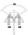
但因传统的钨丝灯泡的光源是360°之投射光,而目前以LED(SMD、晶片)为光源所制作之灯泡2、3、4(如附图1至附图3所示),均只能做单向投射光。此种单向投射光的LED灯泡2、3、4之设计仅可以提供天花板向地板方向照射的灯具(DOWM LIGHT)使用,若是要使用在立灯5(见附图13)、台灯6(见附图14)、壁灯7或床头灯7(见附图15)上,其投射光方向只能往天花板的方向投射光束(见附图4的D1),对于往地板方向之投射光(见附图4的D2)仅能靠着照射在立灯、台灯、壁灯或床头灯之灯罩之斜面的反射光来照明,明显地具有照度不足之问题。因此在钨丝灯泡退场后,此型灯具均由HCFL(热阴极灯管)、CCFL(冷阴极灯管)型的省电灯泡取代。However, because the light source of the traditional tungsten bulb is a 360° projected light, the
然HCFL(热阴极灯管)、CCFL(冷阴极灯管)型的省电灯泡具有紫外线、电磁波及辐射等,有害人体,若是近身使用,伤害更巨,且其含有汞物质及氩、氖等成份,其中汞对于人体脑部、肾脏、皮肤之伤害以及对于土地之污染更具杀伤力。再者,HCFL(热阴极灯管)、CCFL(冷阴极灯管)之灯泡均为玻璃材质,极易破碎,当破碎时汞金属可能逸散,若人体接触或吸入会造成脑部及肾脏之病变。而为分解HCFL(热阴极灯管)、CCFL(冷阴极灯管)报废品之毒性,所耗之成本巨大,并不符环保需求。此外,HCFL(热阴极灯管)、CCFL(冷阴极灯管)型灯泡如同日光灯一样是以电极撞击汞气体放电,所产生的光束为不连续光,其会造成眼睛之视觉困乏,不利于阅读。However, HCFL (Hot Cathode Lamp) and CCFL (Cold Cathode Lamp) energy-saving light bulbs have ultraviolet rays, electromagnetic waves, and radiation, which are harmful to the human body. If they are used close to them, the damage will be even greater, and they contain mercury, argon, neon, etc. Among them, mercury is more lethal to human brain, kidney, skin damage and land pollution. Furthermore, the bulbs of HCFL (Hot Cathode Lamp) and CCFL (Cold Cathode Lamp) are made of glass and are easily broken. When broken, mercury metal may escape. If the human body touches or inhales it, it will cause damage to the brain and kidneys. lesion. To decompose the toxicity of HCFL (Hot Cathode Lamp) and CCFL (Cold Cathode Lamp) waste products requires a huge cost, which does not meet the requirements of environmental protection. In addition, HCFL (Hot Cathode Lamp) and CCFL (Cold Cathode Lamp) bulbs, like fluorescent lamps, are discharged by hitting mercury gas with electrodes, and the light beam produced is discontinuous, which will cause visual fatigue to the eyes and is not conducive to reading .
因此,如何将LED灯泡设计成能符合例如立灯、台灯、壁灯或床头灯等灯具之使用及增加投射光之照射范围,实为LED业者当务之急,更是促进环保、节能之必要手段。Therefore, how to design LED bulbs to meet the use of lamps such as standing lamps, table lamps, wall lamps or bedside lamps and to increase the irradiation range of projected light is an urgent task for LED manufacturers, and it is also a necessary means to promote environmental protection and energy saving.
发明内容Contents of the invention
有鉴于上述课题,本发明之目的即在提供一种360°全射角之高照度LED灯泡。In view of the above problems, the object of the present invention is to provide a high-illuminance LED light bulb with a 360° full-radiation angle.
本发明是通过如下技术方案实现的:该高照度LED灯泡包含一透光灯座,其包含隔开的下端与上端,该透光灯座的下端安装一灯头,该透光灯座的上端开成一开口,该透光灯座的内部安装一驱动器。该高照度LED灯泡更包含一透光灯罩,其结合在透光灯座之上端且封闭该开口使得该透光灯座与该透光灯罩共同界定一容室。一支撑板是受支持地设在该容室内,该支撑板包含面向该透光灯罩的上端面及面向该灯头的下端面。一散热体设在该容室内且受该支撑板承载,该散热体包含面向该透光灯罩的上表面及面向该灯头的下表面。一第一发光模组设于该散热体的上表面且具有至少一个第一LED,该第一发光模组与该驱动器电性连接使得该第一LED可受驱动朝该透光灯罩投射光线。一第二发光模组设于该散热体的下表面且具有至少一个第二LED,该第二发光模组与该驱动器电性连接使得该第二LED可受驱动而朝该透光灯座投射光线。第一、第二基板之LED分别作成上投射光及下投射光,且上投射光投射在透光灯罩开成的反射晕光构成介于上、下投射面间距的侧投射晕光,进而形成360°全射角的投射晕光。The present invention is achieved through the following technical solutions: the high-illuminance LED light bulb includes a light-transmitting lamp holder, which includes a separated lower end and an upper end, a lamp cap is installed on the lower end of the light-transmitting lamp holder, and the upper end of the light-transmitting lamp holder is opened. An opening is formed, and a driver is installed inside the light-transmitting lamp holder. The high-illuminance LED light bulb further includes a light-transmitting lampshade, which is combined with the upper end of the light-transmitting lamp holder and closes the opening so that the light-transmitting lamp holder and the light-transmitting lampshade jointly define a chamber. A support plate is supported in the chamber, and the support plate includes an upper end surface facing the light-transmitting lampshade and a lower end surface facing the lamp cap. A radiator is arranged in the chamber and is carried by the support plate. The radiator includes an upper surface facing the light-transmitting lampshade and a lower surface facing the lamp cap. A first light-emitting module is arranged on the upper surface of the radiator and has at least one first LED. The first light-emitting module is electrically connected to the driver so that the first LED can be driven to project light toward the transparent lampshade. A second light-emitting module is arranged on the lower surface of the radiator and has at least one second LED, and the second light-emitting module is electrically connected to the driver so that the second LED can be driven to project toward the light-transmitting lamp holder light. The LEDs of the first and second substrates are respectively made into the upper projection light and the lower projection light, and the reflection halo formed by the projection of the upper projection light on the light-transmitting lampshade constitutes the side projection halo light between the upper and lower projection surface distances, thereby forming 360° projection halo.
据此,可令使用于立灯、台灯、壁灯或床头灯等灯具的LED灯泡之投射光形成全射角,形成室内空间所需的照明效果以及达到使用者阅读照明之需要。Accordingly, the projected light of LED bulbs used in lamps such as standing lamps, table lamps, wall lamps, or bedside lamps can form a full angle of incidence, forming the lighting effect required by the indoor space and meeting the needs of users for reading lighting.
在一实施例中,该第一发光模组具有第一基板,该第一基板设在设于该散热体的上表面,且该第一LED设于该第一基板上;该第二发光模组具有第二基板,该第二基板设在设于该散热体的下表面,且该第二LED设于该第二基板上。In one embodiment, the first light-emitting module has a first substrate, the first substrate is arranged on the upper surface of the heat sink, and the first LED is arranged on the first substrate; the second light-emitting module The set has a second substrate, the second substrate is arranged on the lower surface of the radiator, and the second LED is arranged on the second substrate.
在一实施例中,该支撑板为一透光性支撑板,该透光灯座之上端的内壁设有一台阶,该透光性支撑板安装在该台阶上。In one embodiment, the support plate is a light-transmitting support plate, and a step is provided on the inner wall of the upper end of the light-transmitting lamp holder, and the light-transmitting support plate is installed on the step.
在一实施例中,该第一基板是与该透光性支撑板结合成为一体使得该第一基板安装在台阶上。In one embodiment, the first substrate is integrated with the light-transmitting support plate so that the first substrate is installed on the steps.
在一实施例中,该第二基板是与该透光性支撑板结合成为一体使得该第二基板安装在台阶上。In one embodiment, the second substrate is integrated with the light-transmitting support plate so that the second substrate is installed on the steps.
关于本发明之其他目的、优点及特征,将由以下较佳实施例的详细说明并参照所附图来了解。Other objectives, advantages and features of the present invention will be understood from the following detailed description of the preferred embodiments with reference to the accompanying drawings.
附图说明Description of drawings
图1为第一习知灯泡的示意图Fig. 1 is the schematic diagram of the first conventional light bulb
图2为第二习知灯泡的示意图Fig. 2 is the schematic diagram of the second conventional light bulb
图3为第三习知灯泡的示意图Fig. 3 is the schematic diagram of the 3rd conventional light bulb
图4为习知灯泡投射光示意图Fig. 4 is a schematic diagram of conventional light bulb projected light
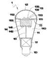
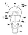
图5为本发明灯泡之第一较佳实施例Fig. 5 is the first preferred embodiment of the light bulb of the present invention
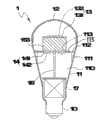
图6为本发明灯泡之第二较佳实施例Fig. 6 is the second preferred embodiment of the light bulb of the present invention
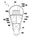
图7为本发明灯泡之第三较佳实施例Fig. 7 is the third preferred embodiment of the light bulb of the present invention
图8为本发明灯泡之第四较佳实施例Fig. 8 is the fourth preferred embodiment of the light bulb of the present invention
图9为本发明灯泡之第五较佳实施例Fig. 9 is the fifth preferred embodiment of the light bulb of the present invention
图10为本发明灯泡之第六较佳实施例Fig. 10 is the sixth preferred embodiment of the light bulb of the present invention
图11为本发明灯泡之第七较佳实施例Fig. 11 is the seventh preferred embodiment of the light bulb of the present invention
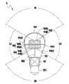
图12为本发明灯泡之投射光示意图Fig. 12 is a schematic diagram of projected light of the bulb of the present invention
图13为本发明灯泡使用于立灯的示意图Fig. 13 is a schematic diagram of a bulb of the present invention used in a standing lamp
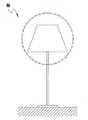
图14为本发明灯泡使用于台灯的示意图Figure 14 is a schematic diagram of the bulb of the present invention used in a desk lamp
图15为本发明灯泡使用于壁灯的示意图Fig. 15 is a schematic diagram of a bulb of the present invention used in a wall lamp
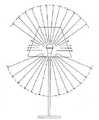
图16为本发明灯泡使用于立灯的投射光示意图Figure 16 is a schematic diagram of projected light when the light bulb of the present invention is used in a standing lamp
符号说明:Symbol Description:
1、灯泡 10、灯头1.
11、透光灯座 110、容室11. Translucent lamp holder 110. Containment chamber
111、台阶 112、透光性支撑板111.
113、孔洞 114、上端113.
115、上端面 116、下端面115.
117、上表面 118、下表面117.
119、下端 2、透光灯罩119. Lower end 2. Translucent lampshade
13、第一发光模组 131、第一基板13. The first light-emitting
132、第一LED 14、第二发光模组132. The
141、第二基板 142、第二LED141.
151、第一散热体 152、第二散热体151. The
153、散热体 17、驱动器153.
18、导线 2、3、4灯泡18.
5、立灯 6、台灯5. Standing
7、壁灯。7. Wall lamp.
具体实施方式Detailed ways
如附图5所示,本发明360°全射角之高照度LED灯泡1之第一较佳实施例:该灯泡1包含一透光灯座11、一透光灯罩12、一透光性支撑板112、一散热体153、一第一发光模组13及一第二发光模组14。该透光灯座11包含隔开的下端119与上端114,该透光灯座11的下端119安装一灯头10,该透光灯座11的上端114形成一开口19。该透光灯罩12结合在该透光灯座11之上端114且封闭该开口19使得该透光灯座11与该透光灯罩12共同界定一容室110,该容室110内部安装一驱动器17,该透光灯座11之上端114内壁环设一台阶111。该透光性支撑板112是架设在该台阶111上以受支持地设在该容室110内,该透光性支撑板112包含面向该透光灯罩12的上端面115及面向该灯头10的下端面116。As shown in Figure 5, the first preferred embodiment of the high-illuminance LED
散热体153设在容室110内且受透光性支撑板112承载,散热体153包含面向透光灯罩12的上表面117及面向灯头10的下表面118。在本实施例中,散热体153包含位在透光性支撑板112之上端面115的第一散热体151及位在支撑板112之下端面116的第二散热体152,第一、第二散热体151、152可利用例如螺丝的固定件(未图示)结合在透光性支撑板112上。第一发光模组13具有一第一基板131以及数个设于该基板131上的第一LED(SMD/晶片)132,在本实施例中,第一基板131设于第一散热体151的上表面。第二发光模组14具有一设于该第二散热体152下端面的第二基板141以及数个设于该第二基板141上的第二LED(SMD/晶片)142,在本实施例中,第二基板141是设于该第二散热体152的下表面。再者,驱动器17是与第一、第二发光模组13、14利用导线18电性连接,使得第一LED132可受驱动而朝透光灯罩12投射光线且第二LED142可受驱动而朝透光灯座11投射光线。The
如附图6所示,本发明360°全射角之高照度LED灯泡1之第二较佳实施例,其与该第一较佳实施例之差异在于,该透光性支撑板112之中心设有一孔洞113,该散热体153设在该透光性支撑板112之下端面116,第一基板131及第一LED132位在该散热体153的上表面,第二基板141及第二LED142位在该散热体153的下表面,第一基板131设于该透光性支撑板112的孔洞113内。As shown in accompanying drawing 6, the second preferred embodiment of the high-illuminance LED
如附图7所示,本发明360°全射角之高照度LED灯泡1之第三较佳实施例,其与该第二较佳实施例之差异在于,该第一基板131设于该透光性支撑板112之下端面116,且该第一LED132设于第一基板131上并对应设于该孔洞113内。As shown in accompanying drawing 7, the third preferred embodiment of the high-illuminance LED
如附图8所示,本发明360°全射角之高照度LED灯泡1之第四较佳实施例,其与该第二较佳实施例之差异在于,散热体153设于该透光性支撑板112的上端面115,散热体153之上、下表面分别设有第一基板131与第二基板141,第一、第二基板131、141上分别设有第一、第二LED132、142,该第二基板141对应设于该孔洞113内。As shown in accompanying drawing 8, the fourth preferred embodiment of the high-illuminance LED
如附图9所示,本发明360°全射角之高照度LED灯泡1之第五较佳实施例,其与该第四较佳实施例之差异在于,该第二基板141设于该透光性支撑板112的上端面,且该第二LED142设于该第二基板141上并对应设于该孔洞113内。As shown in accompanying drawing 9, the fifth preferred embodiment of the high-illuminance LED
如附图10所示,本发明360°全射角之高照度LED灯泡1之第六较佳实施例,其与上述较佳实施例之差异在于,由该第一基板131做为该透性支撑板(即将附图6的透光性支撑板112与第一基板131合为一体),第一基板131承载于该台阶111上,第一基板131上设有数个第一LED(SMD/晶片)132,散热体153位在第一基板131之下端面,第二基板141位于该散热体153的下表面,第二基板141上设有数个第二LED(SMD/晶片)142。As shown in Figure 10, the sixth preferred embodiment of the high-illuminance LED
如附图11所示,本发明360°全射角之高照度LED灯泡1之第七较佳实施例,其与第六实施例之差异在于,由该第二基板141做为该透光性支撑板,第二基板141承载于该台阶111上,第二基板141上设有数个第二LED(SMD/晶片)142,散热体153位在第二基板141之上端面,第一基板131位于该散热体153的上表面,第一基板131上设有数个第一LED(SMD/晶片)132。As shown in Figure 11, the seventh preferred embodiment of the high-illuminance LED
如附图12所示,本发明之投光示意图,藉由第一、第二发光模组13、14之第一、第二LED(SMD/晶片)132、142分别作上投射光A及下投射光B,并利用该上投射光A在该透光灯罩12形成的反射晕光,而构成介于上、下投射光A、B的侧投晕光C、D,进而形成360°全射角的投射晕光。As shown in Figure 12, the schematic diagram of the light projection of the present invention uses the first and second LEDs (SMD/chip) 132 and 142 of the first and second
本发明之各较佳实施例之灯泡1适用装置于如附图13之立灯5、附图14之台灯6、附图15之壁灯7或床头灯上。附图16是显示本发明灯泡1使用于立灯5之投光示意图。The
在前述说明书中,本创作仅是就特定实施例做描述,而依本创作的设计特征是可做多种变化或修改。所以,对于熟悉此项技艺人士可作明显替换与修饰,仍将并入本发明所主张的权利范围之内。In the foregoing specification, the invention is only described in terms of specific embodiments, and various changes or modifications can be made according to the design features of the invention. Therefore, those skilled in the art can make obvious substitutions and modifications, which will still be incorporated within the claimed scope of the present invention.
Claims (8)
Priority Applications (1)
| Application Number | Priority Date | Filing Date | Title |
|---|---|---|---|
| CN2011100924218ACN102155664A (en) | 2011-04-13 | 2011-04-13 | 360° high-intensity LED bulb with full beam angle |
Applications Claiming Priority (1)
| Application Number | Priority Date | Filing Date | Title |
|---|---|---|---|
| CN2011100924218ACN102155664A (en) | 2011-04-13 | 2011-04-13 | 360° high-intensity LED bulb with full beam angle |
Publications (1)
| Publication Number | Publication Date |
|---|---|
| CN102155664Atrue CN102155664A (en) | 2011-08-17 |
Family
ID=44437272
Family Applications (1)
| Application Number | Title | Priority Date | Filing Date |
|---|---|---|---|
| CN2011100924218APendingCN102155664A (en) | 2011-04-13 | 2011-04-13 | 360° high-intensity LED bulb with full beam angle |
Country Status (1)
| Country | Link |
|---|---|
| CN (1) | CN102155664A (en) |
Cited By (19)
| Publication number | Priority date | Publication date | Assignee | Title |
|---|---|---|---|---|
| CN102494258A (en)* | 2011-12-31 | 2012-06-13 | 深圳市聚作实业有限公司 | Light-emitting diode (LED) lamp bulb provided with LED light source combinations on double sides and capable of emitting light in wide angle |
| CN102563416A (en)* | 2011-12-14 | 2012-07-11 | 中山市明达丰电子灯饰有限公司 | LED energy-saving lamp |
| CN102606913A (en)* | 2012-02-17 | 2012-07-25 | 漳州市立达信绿色照明有限公司 | Large-angle LED (light emitting diode) lamp |
| CN102679215A (en)* | 2012-04-28 | 2012-09-19 | 宁波市鄞州威迪电子有限公司 | Light emitting diode (LED) bulb |
| CN102748602A (en)* | 2012-04-12 | 2012-10-24 | 胡文松 | LED bulb structure with enlarged edge light |
| CN102748615A (en)* | 2012-06-20 | 2012-10-24 | 无锡正光源光电技术有限公司 | Entire-light-emitting LED (Light Emitting Diode) bulb lamp |
| CN103115256A (en)* | 2012-12-12 | 2013-05-22 | 苏州朗米尔照明科技有限公司 | Light emitting diode (LED) bulb lamp |
| CN103225771A (en)* | 2012-01-31 | 2013-07-31 | 艺创有限公司 | Led street lamp structure |
| CN103256497A (en)* | 2013-03-05 | 2013-08-21 | 胡文松 | Full beam angle LED bulb structure |
| CN103363354A (en)* | 2013-06-28 | 2013-10-23 | 宁波福泰电器有限公司 | LED lamp manufactured by imitating illuminating angle of incandescent lamp |
| CN103423672A (en)* | 2013-08-26 | 2013-12-04 | 立达信绿色照明股份有限公司 | Large-angle LED (light emitting diode) bulb lamp |
| CN103807622A (en)* | 2012-11-09 | 2014-05-21 | 欧司朗有限公司 | Illumination device |
| CN103851372A (en)* | 2012-12-04 | 2014-06-11 | 展晶科技(深圳)有限公司 | LED (Light-Emitting Diode) lamp bulb |
| CN103982824A (en)* | 2014-05-28 | 2014-08-13 | 昆山生态屋建筑技术有限公司 | Reflector lamp provided with hemispheric diffusion shell and adjustable in angle |
| CN104040253A (en)* | 2011-08-29 | 2014-09-10 | 株式会社Kmw | Spherical lamp with easy heat dissipation |
| CN104033798A (en)* | 2014-06-25 | 2014-09-10 | 昆山天重星光电科技有限公司 | Spotlight with spherical diffuser |
| CN105240744A (en)* | 2014-10-29 | 2016-01-13 | 中山市四维家居照明有限公司 | American vintage wall lamp |
| CN105674128A (en)* | 2014-11-19 | 2016-06-15 | 刘元周 | LED lamp structure |
| WO2016165105A1 (en)* | 2015-04-16 | 2016-10-20 | 正屋(厦门)电子有限公司 | Double-faced led lamp structure |
Citations (7)
| Publication number | Priority date | Publication date | Assignee | Title |
|---|---|---|---|---|
| CN1391291A (en)* | 2001-06-11 | 2003-01-15 | 张修恒 | Semiconductor package structure for white dual-crystal LED |
| CN200949790Y (en)* | 2006-07-18 | 2007-09-19 | 贵州首朗新能源有限公司 | Omnibearing stereo lighting LED lighting lamp |
| CN101303478A (en)* | 2007-05-09 | 2008-11-12 | 奇美电子股份有限公司 | Liquid crystal display device and backlight module thereof |
| CN201273467Y (en)* | 2008-08-29 | 2009-07-15 | 北京中庆微数字设备开发有限公司 | LED decoration lamp |
| CN201348177Y (en)* | 2009-01-19 | 2009-11-18 | 冠捷投资有限公司 | Side light type backlight module |
| CN101581408A (en)* | 2009-07-01 | 2009-11-18 | 北京高科能光电技术有限公司 | LED bulb |
| JP2010129300A (en)* | 2008-11-26 | 2010-06-10 | Keiji Iimura | Semiconductor light-emitting lamp and electric-bulb-shaped semiconductor light-emitting lamp |
- 2011
- 2011-04-13CNCN2011100924218Apatent/CN102155664A/enactivePending
Patent Citations (7)
| Publication number | Priority date | Publication date | Assignee | Title |
|---|---|---|---|---|
| CN1391291A (en)* | 2001-06-11 | 2003-01-15 | 张修恒 | Semiconductor package structure for white dual-crystal LED |
| CN200949790Y (en)* | 2006-07-18 | 2007-09-19 | 贵州首朗新能源有限公司 | Omnibearing stereo lighting LED lighting lamp |
| CN101303478A (en)* | 2007-05-09 | 2008-11-12 | 奇美电子股份有限公司 | Liquid crystal display device and backlight module thereof |
| CN201273467Y (en)* | 2008-08-29 | 2009-07-15 | 北京中庆微数字设备开发有限公司 | LED decoration lamp |
| JP2010129300A (en)* | 2008-11-26 | 2010-06-10 | Keiji Iimura | Semiconductor light-emitting lamp and electric-bulb-shaped semiconductor light-emitting lamp |
| CN201348177Y (en)* | 2009-01-19 | 2009-11-18 | 冠捷投资有限公司 | Side light type backlight module |
| CN101581408A (en)* | 2009-07-01 | 2009-11-18 | 北京高科能光电技术有限公司 | LED bulb |
Cited By (27)
| Publication number | Priority date | Publication date | Assignee | Title |
|---|---|---|---|---|
| CN104040253A (en)* | 2011-08-29 | 2014-09-10 | 株式会社Kmw | Spherical lamp with easy heat dissipation |
| US9857069B2 (en) | 2011-08-29 | 2018-01-02 | Kmw Inc. | Spherical lamp with easy heat dissipation |
| CN104040253B (en)* | 2011-08-29 | 2018-01-05 | 株式会社 Kmw | Spherical Lamps for Ease of Heat Dissipation |
| CN102563416A (en)* | 2011-12-14 | 2012-07-11 | 中山市明达丰电子灯饰有限公司 | LED energy-saving lamp |
| CN102494258A (en)* | 2011-12-31 | 2012-06-13 | 深圳市聚作实业有限公司 | Light-emitting diode (LED) lamp bulb provided with LED light source combinations on double sides and capable of emitting light in wide angle |
| CN103225771A (en)* | 2012-01-31 | 2013-07-31 | 艺创有限公司 | Led street lamp structure |
| CN102606913A (en)* | 2012-02-17 | 2012-07-25 | 漳州市立达信绿色照明有限公司 | Large-angle LED (light emitting diode) lamp |
| CN102606913B (en)* | 2012-02-17 | 2014-11-19 | 立达信绿色照明股份有限公司 | Large-angle LED (light emitting diode) lamp |
| CN102748602A (en)* | 2012-04-12 | 2012-10-24 | 胡文松 | LED bulb structure with enlarged edge light |
| CN102679215A (en)* | 2012-04-28 | 2012-09-19 | 宁波市鄞州威迪电子有限公司 | Light emitting diode (LED) bulb |
| CN102748615A (en)* | 2012-06-20 | 2012-10-24 | 无锡正光源光电技术有限公司 | Entire-light-emitting LED (Light Emitting Diode) bulb lamp |
| CN103807622A (en)* | 2012-11-09 | 2014-05-21 | 欧司朗有限公司 | Illumination device |
| CN103851372B (en)* | 2012-12-04 | 2016-06-29 | 展晶科技(深圳)有限公司 | Light emitting diode bulb |
| CN103851372A (en)* | 2012-12-04 | 2014-06-11 | 展晶科技(深圳)有限公司 | LED (Light-Emitting Diode) lamp bulb |
| CN103115256A (en)* | 2012-12-12 | 2013-05-22 | 苏州朗米尔照明科技有限公司 | Light emitting diode (LED) bulb lamp |
| CN103115256B (en)* | 2012-12-12 | 2016-03-30 | 苏州朗米尔照明科技有限公司 | A kind of LEDbulb lamp |
| CN103256497A (en)* | 2013-03-05 | 2013-08-21 | 胡文松 | Full beam angle LED bulb structure |
| CN103363354A (en)* | 2013-06-28 | 2013-10-23 | 宁波福泰电器有限公司 | LED lamp manufactured by imitating illuminating angle of incandescent lamp |
| CN103423672A (en)* | 2013-08-26 | 2013-12-04 | 立达信绿色照明股份有限公司 | Large-angle LED (light emitting diode) bulb lamp |
| CN103982824A (en)* | 2014-05-28 | 2014-08-13 | 昆山生态屋建筑技术有限公司 | Reflector lamp provided with hemispheric diffusion shell and adjustable in angle |
| CN104033798A (en)* | 2014-06-25 | 2014-09-10 | 昆山天重星光电科技有限公司 | Spotlight with spherical diffuser |
| CN105240744A (en)* | 2014-10-29 | 2016-01-13 | 中山市四维家居照明有限公司 | American vintage wall lamp |
| CN105258028A (en)* | 2014-10-29 | 2016-01-20 | 中山市四维家居照明有限公司 | Composite LED wall lamp with good heat radiation effect |
| CN105258029A (en)* | 2014-10-29 | 2016-01-20 | 中山市四维家居照明有限公司 | European-style LED hall wall lamp with good heat radiation effect |
| CN105333364A (en)* | 2014-10-29 | 2016-02-17 | 中山市四维家居照明有限公司 | A European-style living room LED wall lamp |
| CN105674128A (en)* | 2014-11-19 | 2016-06-15 | 刘元周 | LED lamp structure |
| WO2016165105A1 (en)* | 2015-04-16 | 2016-10-20 | 正屋(厦门)电子有限公司 | Double-faced led lamp structure |
Similar Documents
| Publication | Publication Date | Title |
|---|---|---|
| CN102155664A (en) | 360° high-intensity LED bulb with full beam angle | |
| JP3159158U (en) | LED lighting device with good illumination brightness | |
| JP5378481B2 (en) | High illumination LED bulb with 360 degree shot angle | |
| CN101806406A (en) | LED bulb lamp capable of improving light transmittance | |
| CN202012774U (en) | Integrated heat-dissipation LED (light-emitting diode) down lamp | |
| CN201014246Y (en) | Plastic cover LED illuminating lamp | |
| JP3158325U (en) | Recessed LED lamp with reflector | |
| CN102748602A (en) | LED bulb structure with enlarged edge light | |
| CN204062580U (en) | A kind of LED lamp | |
| CN101220938B (en) | Lower convex type LED integrated lamp cap | |
| CN203202675U (en) | LED bulb | |
| CN107435870B (en) | The LED area light source shot-light of easy heat radiation | |
| TWI407053B (en) | High illumination led bulb with a full emission angle | |
| CN205640264U (en) | One -way polarisation lamp | |
| CN204647949U (en) | A kind of line lamp | |
| CN103216740B (en) | Tubular LED lighting assembly | |
| CN203744114U (en) | Lampshade and LED lamp bulb | |
| CN203585983U (en) | Energy-saving LED ceiling lamp | |
| TWM448610U (en) | LED lamp | |
| CN202327699U (en) | Light emitting diode (LED) lighting device with mirror image reflector | |
| JP5335031B2 (en) | All shot angle high illumination LED bulb | |
| CN201096314Y (en) | Desk lamp | |
| CN207740921U (en) | Intelligent light-controlled LED road lamps | |
| CN207262351U (en) | A kind of LED spotlights of varifocal darkening | |
| CN204756525U (en) | Novel LED lamp |
Legal Events
| Date | Code | Title | Description |
|---|---|---|---|
| C06 | Publication | ||
| PB01 | Publication | ||
| C10 | Entry into substantive examination | ||
| SE01 | Entry into force of request for substantive examination | ||
| RJ01 | Rejection of invention patent application after publication | Application publication date:20110817 | |
| RJ01 | Rejection of invention patent application after publication |