CN102149628A - Switches for Microfluidic Systems - Google Patents
Switches for Microfluidic SystemsDownload PDFInfo
- Publication number
- CN102149628A CN102149628ACN2009801359979ACN200980135997ACN102149628ACN 102149628 ACN102149628 ACN 102149628ACN 2009801359979 ACN2009801359979 ACN 2009801359979ACN 200980135997 ACN200980135997 ACN 200980135997ACN 102149628 ACN102149628 ACN 102149628A
- Authority
- CN
- China
- Prior art keywords
- substrate
- microfluidic
- functional component
- microfluidic channel
- microfluidic system
- Prior art date
- Legal status (The legal status is an assumption and is not a legal conclusion. Google has not performed a legal analysis and makes no representation as to the accuracy of the status listed.)
- Granted
Links
Images


Classifications
- B—PERFORMING OPERATIONS; TRANSPORTING
- B01—PHYSICAL OR CHEMICAL PROCESSES OR APPARATUS IN GENERAL
- B01L—CHEMICAL OR PHYSICAL LABORATORY APPARATUS FOR GENERAL USE
- B01L3/00—Containers or dishes for laboratory use, e.g. laboratory glassware; Droppers
- B01L3/50—Containers for the purpose of retaining a material to be analysed, e.g. test tubes
- B01L3/502—Containers for the purpose of retaining a material to be analysed, e.g. test tubes with fluid transport, e.g. in multi-compartment structures
- B01L3/5027—Containers for the purpose of retaining a material to be analysed, e.g. test tubes with fluid transport, e.g. in multi-compartment structures by integrated microfluidic structures, i.e. dimensions of channels and chambers are such that surface tension forces are important, e.g. lab-on-a-chip
- B01L3/502707—Containers for the purpose of retaining a material to be analysed, e.g. test tubes with fluid transport, e.g. in multi-compartment structures by integrated microfluidic structures, i.e. dimensions of channels and chambers are such that surface tension forces are important, e.g. lab-on-a-chip characterised by the manufacture of the container or its components
- B—PERFORMING OPERATIONS; TRANSPORTING
- B01—PHYSICAL OR CHEMICAL PROCESSES OR APPARATUS IN GENERAL
- B01L—CHEMICAL OR PHYSICAL LABORATORY APPARATUS FOR GENERAL USE
- B01L3/00—Containers or dishes for laboratory use, e.g. laboratory glassware; Droppers
- B01L3/50—Containers for the purpose of retaining a material to be analysed, e.g. test tubes
- B01L3/502—Containers for the purpose of retaining a material to be analysed, e.g. test tubes with fluid transport, e.g. in multi-compartment structures
- B01L3/5023—Containers for the purpose of retaining a material to be analysed, e.g. test tubes with fluid transport, e.g. in multi-compartment structures with a sample being transported to, and subsequently stored in an absorbent for analysis
- B—PERFORMING OPERATIONS; TRANSPORTING
- B01—PHYSICAL OR CHEMICAL PROCESSES OR APPARATUS IN GENERAL
- B01L—CHEMICAL OR PHYSICAL LABORATORY APPARATUS FOR GENERAL USE
- B01L3/00—Containers or dishes for laboratory use, e.g. laboratory glassware; Droppers
- B01L3/50—Containers for the purpose of retaining a material to be analysed, e.g. test tubes
- B01L3/502—Containers for the purpose of retaining a material to be analysed, e.g. test tubes with fluid transport, e.g. in multi-compartment structures
- B01L3/5027—Containers for the purpose of retaining a material to be analysed, e.g. test tubes with fluid transport, e.g. in multi-compartment structures by integrated microfluidic structures, i.e. dimensions of channels and chambers are such that surface tension forces are important, e.g. lab-on-a-chip
- B01L3/502738—Containers for the purpose of retaining a material to be analysed, e.g. test tubes with fluid transport, e.g. in multi-compartment structures by integrated microfluidic structures, i.e. dimensions of channels and chambers are such that surface tension forces are important, e.g. lab-on-a-chip characterised by integrated valves
- F—MECHANICAL ENGINEERING; LIGHTING; HEATING; WEAPONS; BLASTING
- F16—ENGINEERING ELEMENTS AND UNITS; GENERAL MEASURES FOR PRODUCING AND MAINTAINING EFFECTIVE FUNCTIONING OF MACHINES OR INSTALLATIONS; THERMAL INSULATION IN GENERAL
- F16K—VALVES; TAPS; COCKS; ACTUATING-FLOATS; DEVICES FOR VENTING OR AERATING
- F16K99/00—Subject matter not provided for in other groups of this subclass
- F16K99/0001—Microvalves
- B—PERFORMING OPERATIONS; TRANSPORTING
- B01—PHYSICAL OR CHEMICAL PROCESSES OR APPARATUS IN GENERAL
- B01L—CHEMICAL OR PHYSICAL LABORATORY APPARATUS FOR GENERAL USE
- B01L2200/00—Solutions for specific problems relating to chemical or physical laboratory apparatus
- B01L2200/10—Integrating sample preparation and analysis in single entity, e.g. lab-on-a-chip concept
- B—PERFORMING OPERATIONS; TRANSPORTING
- B01—PHYSICAL OR CHEMICAL PROCESSES OR APPARATUS IN GENERAL
- B01L—CHEMICAL OR PHYSICAL LABORATORY APPARATUS FOR GENERAL USE
- B01L2300/00—Additional constructional details
- B01L2300/08—Geometry, shape and general structure
- B01L2300/0861—Configuration of multiple channels and/or chambers in a single devices
- B01L2300/0864—Configuration of multiple channels and/or chambers in a single devices comprising only one inlet and multiple receiving wells, e.g. for separation, splitting
- B—PERFORMING OPERATIONS; TRANSPORTING
- B01—PHYSICAL OR CHEMICAL PROCESSES OR APPARATUS IN GENERAL
- B01L—CHEMICAL OR PHYSICAL LABORATORY APPARATUS FOR GENERAL USE
- B01L2300/00—Additional constructional details
- B01L2300/08—Geometry, shape and general structure
- B01L2300/0861—Configuration of multiple channels and/or chambers in a single devices
- B01L2300/0867—Multiple inlets and one sample wells, e.g. mixing, dilution
- B—PERFORMING OPERATIONS; TRANSPORTING
- B01—PHYSICAL OR CHEMICAL PROCESSES OR APPARATUS IN GENERAL
- B01L—CHEMICAL OR PHYSICAL LABORATORY APPARATUS FOR GENERAL USE
- B01L2300/00—Additional constructional details
- B01L2300/08—Geometry, shape and general structure
- B01L2300/0861—Configuration of multiple channels and/or chambers in a single devices
- B01L2300/087—Multiple sequential chambers
- B—PERFORMING OPERATIONS; TRANSPORTING
- B01—PHYSICAL OR CHEMICAL PROCESSES OR APPARATUS IN GENERAL
- B01L—CHEMICAL OR PHYSICAL LABORATORY APPARATUS FOR GENERAL USE
- B01L2300/00—Additional constructional details
- B01L2300/08—Geometry, shape and general structure
- B01L2300/0861—Configuration of multiple channels and/or chambers in a single devices
- B01L2300/0874—Three dimensional network
- B—PERFORMING OPERATIONS; TRANSPORTING
- B01—PHYSICAL OR CHEMICAL PROCESSES OR APPARATUS IN GENERAL
- B01L—CHEMICAL OR PHYSICAL LABORATORY APPARATUS FOR GENERAL USE
- B01L2300/00—Additional constructional details
- B01L2300/08—Geometry, shape and general structure
- B01L2300/0887—Laminated structure
- B—PERFORMING OPERATIONS; TRANSPORTING
- B01—PHYSICAL OR CHEMICAL PROCESSES OR APPARATUS IN GENERAL
- B01L—CHEMICAL OR PHYSICAL LABORATORY APPARATUS FOR GENERAL USE
- B01L2300/00—Additional constructional details
- B01L2300/12—Specific details about materials
- B01L2300/126—Paper
- B—PERFORMING OPERATIONS; TRANSPORTING
- B01—PHYSICAL OR CHEMICAL PROCESSES OR APPARATUS IN GENERAL
- B01L—CHEMICAL OR PHYSICAL LABORATORY APPARATUS FOR GENERAL USE
- B01L2400/00—Moving or stopping fluids
- B01L2400/04—Moving fluids with specific forces or mechanical means
- B01L2400/0403—Moving fluids with specific forces or mechanical means specific forces
- B01L2400/0406—Moving fluids with specific forces or mechanical means specific forces capillary forces
- B—PERFORMING OPERATIONS; TRANSPORTING
- B01—PHYSICAL OR CHEMICAL PROCESSES OR APPARATUS IN GENERAL
- B01L—CHEMICAL OR PHYSICAL LABORATORY APPARATUS FOR GENERAL USE
- B01L2400/00—Moving or stopping fluids
- B01L2400/06—Valves, specific forms thereof
- B01L2400/0622—Valves, specific forms thereof distribution valves, valves having multiple inlets and/or outlets, e.g. metering valves, multi-way valves
- B—PERFORMING OPERATIONS; TRANSPORTING
- B01—PHYSICAL OR CHEMICAL PROCESSES OR APPARATUS IN GENERAL
- B01L—CHEMICAL OR PHYSICAL LABORATORY APPARATUS FOR GENERAL USE
- B01L2400/00—Moving or stopping fluids
- B01L2400/06—Valves, specific forms thereof
- B01L2400/0633—Valves, specific forms thereof with moving parts
- B—PERFORMING OPERATIONS; TRANSPORTING
- B01—PHYSICAL OR CHEMICAL PROCESSES OR APPARATUS IN GENERAL
- B01L—CHEMICAL OR PHYSICAL LABORATORY APPARATUS FOR GENERAL USE
- B01L2400/00—Moving or stopping fluids
- B01L2400/06—Valves, specific forms thereof
- B01L2400/0677—Valves, specific forms thereof phase change valves; Meltable, freezing, dissolvable plugs; Destructible barriers
- B—PERFORMING OPERATIONS; TRANSPORTING
- B01—PHYSICAL OR CHEMICAL PROCESSES OR APPARATUS IN GENERAL
- B01L—CHEMICAL OR PHYSICAL LABORATORY APPARATUS FOR GENERAL USE
- B01L2400/00—Moving or stopping fluids
- B01L2400/06—Valves, specific forms thereof
- B01L2400/0688—Valves, specific forms thereof surface tension valves, capillary stop, capillary break
- F—MECHANICAL ENGINEERING; LIGHTING; HEATING; WEAPONS; BLASTING
- F16—ENGINEERING ELEMENTS AND UNITS; GENERAL MEASURES FOR PRODUCING AND MAINTAINING EFFECTIVE FUNCTIONING OF MACHINES OR INSTALLATIONS; THERMAL INSULATION IN GENERAL
- F16K—VALVES; TAPS; COCKS; ACTUATING-FLOATS; DEVICES FOR VENTING OR AERATING
- F16K99/00—Subject matter not provided for in other groups of this subclass
- F16K2099/0073—Fabrication methods specifically adapted for microvalves
- F16K2099/0074—Fabrication methods specifically adapted for microvalves using photolithography, e.g. etching
- F—MECHANICAL ENGINEERING; LIGHTING; HEATING; WEAPONS; BLASTING
- F16—ENGINEERING ELEMENTS AND UNITS; GENERAL MEASURES FOR PRODUCING AND MAINTAINING EFFECTIVE FUNCTIONING OF MACHINES OR INSTALLATIONS; THERMAL INSULATION IN GENERAL
- F16K—VALVES; TAPS; COCKS; ACTUATING-FLOATS; DEVICES FOR VENTING OR AERATING
- F16K99/00—Subject matter not provided for in other groups of this subclass
- F16K2099/0073—Fabrication methods specifically adapted for microvalves
- F16K2099/008—Multi-layer fabrications
- F—MECHANICAL ENGINEERING; LIGHTING; HEATING; WEAPONS; BLASTING
- F16—ENGINEERING ELEMENTS AND UNITS; GENERAL MEASURES FOR PRODUCING AND MAINTAINING EFFECTIVE FUNCTIONING OF MACHINES OR INSTALLATIONS; THERMAL INSULATION IN GENERAL
- F16K—VALVES; TAPS; COCKS; ACTUATING-FLOATS; DEVICES FOR VENTING OR AERATING
- F16K99/00—Subject matter not provided for in other groups of this subclass
- F16K2099/0082—Microvalves adapted for a particular use
- F16K2099/0084—Chemistry or biology, e.g. "lab-on-a-chip" technology
- F—MECHANICAL ENGINEERING; LIGHTING; HEATING; WEAPONS; BLASTING
- F16—ENGINEERING ELEMENTS AND UNITS; GENERAL MEASURES FOR PRODUCING AND MAINTAINING EFFECTIVE FUNCTIONING OF MACHINES OR INSTALLATIONS; THERMAL INSULATION IN GENERAL
- F16K—VALVES; TAPS; COCKS; ACTUATING-FLOATS; DEVICES FOR VENTING OR AERATING
- F16K99/00—Subject matter not provided for in other groups of this subclass
- F16K2099/0082—Microvalves adapted for a particular use
- F16K2099/0086—Medical applications
- F—MECHANICAL ENGINEERING; LIGHTING; HEATING; WEAPONS; BLASTING
- F16—ENGINEERING ELEMENTS AND UNITS; GENERAL MEASURES FOR PRODUCING AND MAINTAINING EFFECTIVE FUNCTIONING OF MACHINES OR INSTALLATIONS; THERMAL INSULATION IN GENERAL
- F16K—VALVES; TAPS; COCKS; ACTUATING-FLOATS; DEVICES FOR VENTING OR AERATING
- F16K99/00—Subject matter not provided for in other groups of this subclass
- F16K2099/0082—Microvalves adapted for a particular use
- F16K2099/0092—Inkjet printers
- Y—GENERAL TAGGING OF NEW TECHNOLOGICAL DEVELOPMENTS; GENERAL TAGGING OF CROSS-SECTIONAL TECHNOLOGIES SPANNING OVER SEVERAL SECTIONS OF THE IPC; TECHNICAL SUBJECTS COVERED BY FORMER USPC CROSS-REFERENCE ART COLLECTIONS [XRACs] AND DIGESTS
- Y10—TECHNICAL SUBJECTS COVERED BY FORMER USPC
- Y10T—TECHNICAL SUBJECTS COVERED BY FORMER US CLASSIFICATION
- Y10T436/00—Chemistry: analytical and immunological testing
- Y10T436/25—Chemistry: analytical and immunological testing including sample preparation
- Y10T436/2575—Volumetric liquid transfer
- Y—GENERAL TAGGING OF NEW TECHNOLOGICAL DEVELOPMENTS; GENERAL TAGGING OF CROSS-SECTIONAL TECHNOLOGIES SPANNING OVER SEVERAL SECTIONS OF THE IPC; TECHNICAL SUBJECTS COVERED BY FORMER USPC CROSS-REFERENCE ART COLLECTIONS [XRACs] AND DIGESTS
- Y10—TECHNICAL SUBJECTS COVERED BY FORMER USPC
- Y10T—TECHNICAL SUBJECTS COVERED BY FORMER US CLASSIFICATION
- Y10T83/00—Cutting
- Y10T83/02—Other than completely through work thickness
Landscapes
- Chemical & Material Sciences (AREA)
- Health & Medical Sciences (AREA)
- Clinical Laboratory Science (AREA)
- Analytical Chemistry (AREA)
- General Health & Medical Sciences (AREA)
- Hematology (AREA)
- Dispersion Chemistry (AREA)
- Chemical Kinetics & Catalysis (AREA)
- Engineering & Computer Science (AREA)
- General Engineering & Computer Science (AREA)
- Mechanical Engineering (AREA)
- Physical Or Chemical Processes And Apparatus (AREA)
- Automatic Analysis And Handling Materials Therefor (AREA)
Abstract
Description
Translated fromChinese技术领域technical field
本发明一般涉及微流体系统,并且具体涉及在这种系统中使用的开关、过滤器和其它功能部件。虽然将关于片状的纸基基底描述本发明,但是应理解本发明不局限于由该材料制成的基底,并且可以在其它材料的基底上使用,例如亲水性聚合物基底。The present invention relates generally to microfluidic systems, and in particular to switches, filters and other functional components used in such systems. Although the invention will be described in relation to a paper-based substrate in sheet form, it should be understood that the invention is not limited to substrates made of this material, and may be used on substrates of other materials, such as hydrophilic polymer substrates.
背景技术Background technique
在纸和其它织造和非织造纤维及多孔表面上制造廉价的微流体通道以产生微流体系统的概念已被成功地证明。片状的纸是容易获得的,并且能够制造用于这种微流体系统的非常低成本的基底。建立这种系统的一个目的是制造低成本的生物分析和指示装置,其直接设想的应用是检测饮用水中的水生细菌、体液中的某种特定蛋白质或生物标记的存在(癌症测试)、人或动物血样及尿样中的葡萄糖及其它生化物质的水平。低成本纸基生物分析和环境分析装置的发展到目前为止已允许快速的和单步的反应以检测流体样本中的分析物。由Whitesides领导的哈佛大学的研究者们(见Martinez,A.W.,Phillips,S.T.,Butte,M.J.和Whitesides G.M.,“Platform for Inexpensive,Low-Volume,Portable Bioassays”,Angew.Chem.Int.Ed.46,1318-1320(2007))近来通过印刷常规光致抗蚀剂聚合物(PDMS)图案而在纸上创建通道。纸提供毛细管通道,而光致抗蚀剂聚合物形成定义该通道的屏障。最近,该哈佛的小组使用x-y绘图仪在纸表面上绘制通道(见Bruzewicz,D.A.,Reches,M.和Whitesides,G.M.,“Low-Cost Printing of Poly(dimethylsiloxane)Barriers to Define Microchannels in Paper,Anal Chem.80,3387-3392(2008)以及Martinez,A.W.;Phillips,S.T.;Carrilho,E.;Thomas Ill,S.W.;Sindi,H.;Whitesides,G.M.,“Simple telemedicine for developing regions:camera phones and paper-based microfluidic devices for real-time,off-site diagnosis”.Anal.Chem.80(2008)3699-3707)。将绘图仪的笔填充以聚二甲基硅氧烷(PDMS)在己烷中的疏水溶液,并产生大量带有1cm到2mm宽的通道的10cm长的图案。他们的第二个在纸表面上创建的微通道系统克服了第一个微通道系统的主要缺点,即,常规光致抗蚀剂聚合物的坚硬和易碎的屏障材料。然而,他们的第二个系统具有较差的通道分辨率和清晰度,因为不能控制PDMS溶液在纸张中的穿透度。The concept of fabricating inexpensive microfluidic channels on paper and other woven and nonwoven fibers and porous surfaces to create microfluidic systems has been successfully demonstrated. Sheets of paper are readily available and enable the fabrication of very low cost substrates for such microfluidic systems. One of the purposes of establishing such a system is to make low-cost bioanalytical and indicator devices, the applications immediately envisaged are detection of aquatic bacteria in drinking water, the presence of a certain protein or biomarker in body fluids (cancer testing), human Or levels of glucose and other biochemicals in animal blood and urine samples. The development of low-cost paper-based bioanalytical and environmental analytical devices has so far allowed rapid and single-step reactions to detect analytes in fluid samples. Researchers at Harvard University led by Whitesides (see Martinez, A.W., Phillips, S.T., Butte, M.J., and Whitesides G.M., "Platform for Inexpensive, Low-Volume, Portable Bioassays", Angew. Chem. Int. Ed. 46, 1318-1320 (2007)) recently created channels on paper by printing conventional photoresist polymer (PDMS) patterns. The paper provides the capillary channel, while the photoresist polymer forms the barrier that defines the channel. More recently, this Harvard group used an x-y plotter to map channels on paper surfaces (see Bruzewicz, D.A., Reches, M. and Whitesides, G.M., "Low-Cost Printing of Poly(dimethylsiloxane) Barriers to Define Microchannels in Paper, Anal Chem. .80, 3387-3392 (2008) and Martinez, A.W.; Phillips, S.T.; Carrilho, E.; Thomas Ill, S.W.; Sindi, H.; Whitesides, G.M., “Simple telemedicine for developing regions: camera phones and paper-based microfluidic devices for real-time, off-site diagnosis". Anal. Chem. 80 (2008) 3699-3707). The pen of the plotter is filled with a hydrophobic solution of polydimethylsiloxane (PDMS) in hexane , and produced a large number of 10cm long patterns with 1cm to 2mm wide channels. Their second microchannel system created on the paper surface overcomes the main disadvantage of the first microchannel system, namely, conventional photoresist hard and brittle barrier material of the etchant polymer. However, their second system had poor channel resolution and sharpness because the penetration of the PDMS solution in the paper could not be controlled.
在美国7125639,即分子传递光刻中,发明人Charles Daniel Schaper(分类430/253、430/258)描述了一种用于图案化基底的过程,包括步骤:1)用光敏材料涂覆载体,2)将光敏材料暴露于辐射的图案,以及3)将暴露的材料物理地传递到基底上。In US 7125639, Molecular Delivery Lithography, the inventor Charles Daniel Schaper (classifications 430/253, 430/258) describes a process for patterning a substrate comprising the steps of: 1) coating the support with a photosensitive material, 2) exposing the photosensitive material to a pattern of radiation, and 3) physically transferring the exposed material onto the substrate.
在Paul G Clem等人的美国6518168,即自组装单层直接表面图案化(提交日11/02/1998)中,一种用于形成沉积在表面上的材料的图案的技术包括:在表面上以一图案形成自组装单层,以及经由化学气相沉积或经由溶胶-凝胶处理,以与自组装的单层图案互补的图案在表面上沉积材料。该材料可以是金属、金属氧化物等。In Paul G Clem et al., US 6518168, Direct Surface Patterning of Self-Assembled Monolayers (filed 11/02/1998), a technique for patterning a material deposited on a surface involves: The self-assembled monolayer is formed in a pattern, and material is deposited on the surface in a pattern complementary to the pattern of the self-assembled monolayer, either by chemical vapor deposition or by sol-gel processing. The material may be a metal, a metal oxide, or the like.
在BUTTE,Manish,J.等人的WO/2008/060449,即微流体检测器(申请日9-11/2007)中,提供了用于确定指示疾病状态的分析物的物件和方法。在一些实施例中,这里所描述的物件和方法能够用于定性或定量地确定流体样本中某成分的存在,该成分诸如是特定类型的细胞。在一个具体实施例中,提供了用于快速检测T细胞的低成本微流体系统。该微流体系统可以使用通道中的固定化抗体和粘附分子以从诸如少量血液的流体样本中捕捉T细胞。可以使用专门针对T细胞受体(TCR)的抗体,以金属胶体(例如金纳米微粒)标记所捕捉的T细胞,并且可以将金属银催化沉淀到这些细胞上。可以对所捕捉的T细胞的数量进行计数,并且所捕捉的T细胞的数量可以指示病人的疾病状态,诸如重症综合型免疫缺乏症或人类免疫缺陷病毒。In WO/2008/060449 by BUTTE, Manish, J. et al. Microfluidic detectors (filed 9-11/2007), articles and methods for determining analytes indicative of disease states are provided. In some embodiments, the articles and methods described herein can be used to qualitatively or quantitatively determine the presence of a component, such as a particular type of cell, in a fluid sample. In a specific embodiment, a low-cost microfluidic system for rapid detection of T cells is provided. The microfluidic system can use immobilized antibodies and adhesion molecules in channels to capture T cells from fluid samples such as small amounts of blood. Captured T cells can be labeled with metal colloids (such as gold nanoparticles) using antibodies specific for the T cell receptor (TCR), and metallic silver can be catalytically precipitated onto these cells. The number of captured T cells can be counted and can be indicative of a patient's disease state, such as severe syndrome or human immunodeficiency virus.
上述专利均未描述任何用于在微流体系统中控制流体的运动或以其它方式影响流体的功能部件。另外,不能通过上述系统进行多步骤反应。None of the aforementioned patents describe any functional components for controlling the movement of fluids or otherwise affecting fluids in microfluidic systems. In addition, multi-step reactions cannot be performed by the above-mentioned system.
因此,本发明的一个目的是提供一种包括这种功能部件的微流体系统。It is therefore an object of the present invention to provide a microfluidic system comprising such functional components.
本发明的另一个优选目的是提供一种微流体系统,其允许进行多步骤反应或功能。Another preferred object of the present invention is to provide a microfluidic system which allows multi-step reactions or functions.
发明内容Contents of the invention
根据本发明的一个方面,提供一种微流体系统,包括:片状基底;被支持在该基底的表面上的至少一个亲水性微流体通道;以及被形成为该基底的部分的至少一个功能部件,该功能部件用于提供用于该微流体通道的功能。According to one aspect of the present invention, there is provided a microfluidic system comprising: a sheet-like substrate; at least one hydrophilic microfluidic channel supported on a surface of the substrate; and at least one functional channel formed as part of the substrate A component, the functional component is used to provide the function for the microfluidic channel.
根据一个优选实施例,该功能部件是由设置在该基底内的至少一个切口形成的,该至少一个切口用于定义该基底的部分,该部分能够相对于该基底的其余部分位移,该基底部分支持该微流体通道的至少部分。根据另一个优选实施例,通过设置在基底内的至少一个切口和材料的带形成功能部件,该带通过切口以形成滑动开关,该带由与基底相同或相似的材料构成,其中微流体通道的至少部分被支持在该带上。According to a preferred embodiment, the functional part is formed by at least one cutout provided in the base, the at least one cutout serving to define a part of the base which is displaceable relative to the rest of the base, the base part At least a portion of the microfluidic channel is supported. According to another preferred embodiment, the functional part is formed by at least one cutout provided in the substrate and a strip of material passing through the cutout to form the slide switch, the strip being made of the same or similar material as the substrate, wherein the microfluidic channel At least partially supported on the belt.
该功能部件可提供用于控制流体沿微流体通道的流动的开关。优选地,可以提供多个所述开关,该开关控制反应物从添加区域到至少一个检测区域的流动。可以将所述检测区域设置在每个开关上。可替选地,该开关可以控制多个反应物从多个添加区域到至少一个反应区域的流动。根据另一优选实施例,单个所述开关可以控制流体沿多个微流体通道的流动。The functional component can provide a switch for controlling the flow of fluid along the microfluidic channel. Preferably, a plurality of said switches may be provided which control the flow of reactants from the addition zone to the at least one detection zone. The detection area may be provided on each switch. Alternatively, the switch may control the flow of reactants from the addition zones to the at least one reaction zone. According to another preferred embodiment, a single said switch can control the flow of fluid along multiple microfluidic channels.
根据另一个优选实施例,上述至少一个亲水性通道和(或)至少一个功能部件被形成在两片或更多片相同或不同的基底上。通过启动至少一个片上的至少一个功能部件,允许流体从一片芯吸(wick)到另一片,因此提供能够控制流体在三维纸基微流体装置中的运动的功能部件。According to another preferred embodiment, the above-mentioned at least one hydrophilic channel and/or at least one functional component are formed on two or more same or different substrates. By activating at least one functional component on at least one sheet, fluid is allowed to wick from one sheet to another, thus providing a functional component capable of controlling the movement of fluid in a three-dimensional paper-based microfluidic device.
根据本发明的另一个优选实施例,微流体通道的被功能部件支持的部分可以提供用于微流体通道内的流体的过滤器。According to another preferred embodiment of the present invention, the part of the microfluidic channel supported by the functional part may provide a filter for the fluid inside the microfluidic channel.
本发明优选地提供开关和其它功能部件,其能够在制造在片状基底上的微流体系统上被启动。开关启动系统可以依赖于不同的启动机制,包括:1)机械的,2)电磁的,3)化学的,4)光学的。The present invention preferably provides switches and other functional components that can be actuated on microfluidic systems fabricated on sheet-form substrates. Switch actuation systems can rely on different actuation mechanisms including: 1) mechanical, 2) electromagnetic, 3) chemical, 4) optical.
申请人已开发出在非织造多孔材料上制造微流体通道的新的两步骤方法。该新方法由两步骤过程组成。在第一步中,对表面实施疏水性处理以降低基底的表面能(对于疏水性多孔材料,不需要该步骤)。在第二步中,在经处理的表面上刻蚀所选图案的精确通道。等离子体处理显著地提高该多孔基底的表面能,使其能够被水和水相液体润湿。多孔材料可被液体润湿的性质因此提供毛细管驱动力,并允许液体在由等离子体处理产生的通道内或沿该通道穿过。可以产生各种图案;等离子体处理不在基底表面留下任何可见标记,并且不使材料的柔韧性或硬度改变超过5%。Applicants have developed a new two-step method for fabricating microfluidic channels on nonwoven porous materials. The new method consists of a two-step process. In a first step, a hydrophobic treatment is applied to the surface to reduce the surface energy of the substrate (this step is not required for hydrophobic porous materials). In a second step, precise channels of the selected pattern are etched into the treated surface. Plasma treatment significantly increases the surface energy of the porous substrate, making it wettable by water and aqueous phase liquids. The liquid-wettable property of the porous material thus provides capillary driving force and allows liquid to pass within or along the channels created by the plasma treatment. Various patterns can be produced; the plasma treatment does not leave any visible marks on the substrate surface and does not change the flexibility or hardness of the material by more than 5%.
申请人也已开发出了制造微流体系统的方法,其中疏水剂被印刷在亲水性基底上,以形成定义微流体通道的疏水性/亲水性差异。在申请人的国际专利申请PCT/AU2009/000889号中更详细地描述了以上引述的两个制造方法。Applicants have also developed methods for fabricating microfluidic systems in which hydrophobic agents are printed on hydrophilic substrates to create hydrophobicity/hydrophilicity differences that define microfluidic channels. The two manufacturing methods cited above are described in more detail in the Applicant's International Patent Application No. PCT/AU2009/000889.
可以由机械地影响该系统的任意力来产生更改流体流动的开关启动的机械模式。可以通过真空或通过对该系统的压力来直接地、间接地施加该力。The mechanical pattern of switch actuation altering fluid flow can be produced by any force mechanically affecting the system. The force can be applied directly, indirectly by vacuum or by pressure on the system.
可以由任何允许改变流体流动的电场、磁效应或其结合来产生流体启动触发的电磁模式。Fluid-initiated triggered electromagnetic patterns may be generated by any electric field, magnetic effect, or combination thereof that permits changes in fluid flow.
触发微流体系统开关的化学模式包括任意类型的化学原理。其包括反应,溶解,沉淀,以及疏水性、粘性和光致反应的改变等。其涉及单个或多个反应物、表面活性剂、聚合体、胶体。The chemical pattern that triggers the switch of the microfluidic system includes any type of chemical principle. These include reactions, dissolution, precipitation, and changes in hydrophobicity, viscosity, and photoreaction. It involves single or multiple reactants, surfactants, polymers, colloids.
优选地,本发明还提供在非织造材料上制造微流体图案的方法,该微流体图案具有能够被触发动作启动的过滤器或反应物释放部位。Preferably, the present invention also provides a method of fabricating a microfluidic pattern on a nonwoven material, the microfluidic pattern having a filter or reactant release site that can be activated by a triggering action.
优选地,本发明还提供在纸表面上制作微反应器的方法,该微反应器具有受控的反应物输入。Preferably, the present invention also provides a method of fabricating a microreactor on a paper surface with controlled reactant input.
优选地,本发明还提供便于多步骤反应和测试的方法,该多步骤反应和测试需要反应的每个步骤间的时间延迟。Preferably, the present invention also provides methods that facilitate multi-step reactions and assays that require a time delay between each step of the reaction.
根据本发明的另一个方面,提供一种制造具有片状基底的微流体系统的方法,至少一个亲水性微流体通道被支持在基底的表面上,并且至少一个功能部件被形成为基底的部分,以用于提供用于微流体通道的功能;该方法包括通过在基底内制作至少一个切口来形成功能部件,该切口用于定义基底的部分,该部分能够相对于基底的其余部分位移,该基底部分支持微流体通道的至少部分。According to another aspect of the present invention, there is provided a method of manufacturing a microfluidic system having a sheet-like substrate, at least one hydrophilic microfluidic channel is supported on the surface of the substrate, and at least one functional component is formed as part of the substrate , for providing functionality for microfluidic channels; the method comprises forming the functional component by making at least one cut in the substrate, the cut being used to define a portion of the substrate capable of displacement relative to the rest of the substrate, the The base portion supports at least part of the microfluidic channel.
根据本发明的另一方面,提供一种制造具有片状基底的微流体系统的方法,至少一个亲水性微流体通道被支持在基底的表面上,并且至少一个功能部件被形成为基底的部分,以用于提供用于微流体通道的功能;该方法包括通过在基底内制作至少一个切口,以及使材料的带通过该切口以形成滑动开关,来形成该功能部件,该带由与基底相同或相似的材料形成,微流体通道的至少部分被支持在该带上。According to another aspect of the present invention, there is provided a method of manufacturing a microfluidic system having a sheet-like substrate, at least one hydrophilic microfluidic channel is supported on the surface of the substrate, and at least one functional component is formed as part of the substrate , for providing functionality for microfluidic channels; the method includes forming the functional component by making at least one slit in the substrate, and passing a strip of material through the slit to form a slide switch, the strip being made of the same material as the substrate or similar material, at least part of the microfluidic channel is supported on the tape.
等离子体处理显著提高多孔基底的表面能,使其能够被水和水相液体润湿。多孔材料可被液体润湿的性质因此提供毛细管驱动力,并允许液体在由等离子体处理产生的通道内或沿该通道穿过。Plasma treatment significantly increases the surface energy of porous substrates, enabling them to be wetted by water and aqueous phase liquids. The liquid-wettable property of the porous material thus provides capillary driving force and allows liquid to pass within or along the channels created by the plasma treatment.
将疏水剂印刷到亲水性纸上以在纸上定义微流体图案。使用纸表面上电子生成的印刷图案来制作纸基微流体图案的容易程度使得印刷成为在纸上制造通道的非常令人满意的有效的可选方法。Print the hydrophobic agent onto the hydrophilic paper to define the microfluidic pattern on the paper. The ease with which paper-based microfluidic patterns can be fabricated using electronically generated printed patterns on paper surfaces makes printing a highly desirable and efficient alternative for fabricating channels on paper.
能够制作这种装置的材料包括但不限于:非织物、织物、泡沫材料、合成物、膜以及薄膜。特别感兴趣的是由纤维素材料制成的材料,包括纸和非织物以及织物。感兴趣的纸制品包括滤纸、办公用纸、层析纸、纸巾(手巾纸、面巾纸、湿纸巾、擦拭纸)、新闻用纸、包装纸、非织造聚合物支架(non-woven polymer scaffold)等。Materials from which such devices can be fabricated include, but are not limited to, non-wovens, fabrics, foams, composites, films, and films. Of particular interest are materials made from cellulosic materials, including paper and nonwovens and fabrics. Paper products of interest include filter paper, office paper, chromatography paper, paper towels (towels, facial tissues, wet wipes, wipes), newsprint, wrapping paper, non-woven polymer scaffolds, etc. .
可以选用本领域任何已知的方法来对表面/基底进行疏水化。本发明的一个实施例由吸收或吸附溶解在挥发性溶剂中的疏水性物质的溶液组成。疏水性物质包括但不限于:AKD、ASA、松脂、乳胶、硅树脂、含氟化合物、聚烯烃乳剂、树脂和脂肪酸、天然及合成蜡、以及任何本领域已知的疏水性物质。另一个应用是通过疏水性物质的气相沉积。The surface/substrate can be hydrophobized by any method known in the art. One embodiment of the invention consists of absorbing or adsorbing a solution of a hydrophobic substance dissolved in a volatile solvent. Hydrophobic substances include, but are not limited to: AKD, ASA, rosin, latex, silicone, fluorochemicals, polyolefin emulsions, resins and fatty acids, natural and synthetic waxes, and any hydrophobic substance known in the art. Another application is by vapor deposition of hydrophobic substances.
优选地,本发明可以提供流体图案,用于输运流体以并行分析不同检测区域。典型的通道尺寸可以在1mm到10cm的长度范围以及从2cm到100μm的宽度范围内改变。该流体系统通常具有与原始基底相同的硬度、机械、特性和软度。Preferably, the present invention may provide fluidic patterns for transporting fluids for parallel analysis of different detection regions. Typical channel dimensions can vary from 1 mm to 10 cm in length and from 2 cm to 100 μm in width. The fluidic system typically has the same stiffness, mechanics, properties and softness as the original substrate.
或者,本发明可以提供开关,其能够通过以下方式(但不限于这些方式)启动:接触机械力、非接触机械力(诸如真空和气动空气喷射)、静电和电磁触发机制。Alternatively, the present invention may provide switches that can be actuated by, but not limited to, contact mechanical force, non-contact mechanical force (such as vacuum and pneumatic air jets), electrostatic and electromagnetic trigger mechanisms.
本发明还可以提供用于微流体系统的过滤器、离子交换部位和反应物释放储藏,其能够根据需要被切换到微流体通道中。The present invention can also provide filters, ion exchange sites and reactant release reservoirs for microfluidic systems that can be switched into microfluidic channels as needed.
因此,本发明提供用于在基底上制造廉价的微流体图案系统的简单且通用的技术,该系统包括带有功能部件的柔性基底,基底诸如纸、非织物、泡沫材料和多孔介质,功能部件诸如开关、微反应器和过滤器。应用包括低成本生物检测和指示器,以监视特定健康状态或环境状态。这些功能部件有力地增强了纸微流体系统的能力,使得能够在低成本微流体系统上进行由多于一个反应组成的测试。本发明的优选实施例由使用等离子体处理在多孔、非织物和织物基底上制造微流体装置组成,其中该微流体装置具有功能和智能部件,该等离子体处理使用掩模以及数字或接触印刷方法。Thus, the present invention provides a simple and versatile technique for fabricating inexpensive microfluidic patterning systems on substrates comprising flexible substrates with functional components such as paper, non-wovens, foams and porous media, functional components Such as switches, microreactors and filters. Applications include low-cost biological detection and indicators to monitor specific health or environmental conditions. These functional components strongly enhance the capabilities of paper microfluidic systems, enabling tests consisting of more than one reaction to be performed on low-cost microfluidic systems. A preferred embodiment of the invention consists of fabricating microfluidic devices with functional and intelligent components on porous, non-woven and textile substrates using plasma processing using masks and digital or contact printing methods .
另外,本发明指出建立在纸和其它多孔材料上的微流体系统使得能够进行多步骤反应以及被用作指示器和微反应器的潜能。为了实现该潜能,开关、过滤器和反应部位能够被设计和建立在微流体通道中以控制分析物和指示剂的流动和反应。Additionally, the present invention points to the potential of microfluidic systems built on paper and other porous materials to enable multi-step reactions and to be used as indicators and microreactors. To realize this potential, switches, filters and reaction sites can be designed and built into microfluidic channels to control the flow and reaction of analytes and indicators.
附图说明Description of drawings
参照附图将便于进一步描述本发明,附图示出本发明的示例。其它示例是可能的,因此附图的具体性不应被理解为取代对本发明的上述描述的一般性。The invention will be conveniently further described with reference to the accompanying drawings, which show examples of the invention. Other examples are possible and therefore the specificity of the drawings should not be construed as superseding the generality of the above description of the invention.
在附图中:In the attached picture:
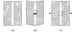
图1(a)至图1(c)是示出本发明的第一示例的图解视图;1(a) to 1(c) are diagrammatic views showing a first example of the present invention;
图2(a)至图2(c)是示出本发明的第二示例的图解视图;2(a) to 2(c) are diagrammatic views showing a second example of the present invention;
图3(a)至图3(c)是示出根据本发明的开关的操作的照片;3(a) to 3(c) are photographs showing the operation of the switch according to the present invention;
图4是本发明的第三示例的图解视图;Figure 4 is a diagrammatic view of a third example of the present invention;
图5是本发明的第四示例的图解视图;Figure 5 is a diagrammatic view of a fourth example of the present invention;
图6是示出图5的示例的操作的图解视图;FIG. 6 is a diagrammatic view illustrating the operation of the example of FIG. 5;
图7是示出工作中的图5的过滤器的照片;Figure 7 is a photograph showing the filter of Figure 5 in action;
图8是本发明的另一示例的图解视图;Figure 8 is a diagrammatic view of another example of the present invention;
图9(a)至图9(e)是示出图8的示例的操作的照片;9(a) to 9(e) are photographs illustrating the operation of the example of FIG. 8;
图10是用于三维纸基微流体系统的控制开关的示意图。Figure 10 is a schematic diagram of a control switch for a three-dimensional paper-based microfluidic system.
具体实施方式Detailed ways
以下说明描述包含根据本发明的功能部件的微流体系统的各种示例。The following description describes various examples of microfluidic systems comprising functional components according to the present invention.
示例1Example 1
首先参照图1至图4,示出了这样的布置,其中以与支持微流体系统的基底相同的材料整体地形成根据本发明的功能部件。Referring first to Figures 1 to 4, arrangements are shown in which functional components according to the invention are integrally formed of the same material as the substrate supporting the microfluidic system.
在本发明的一个示例中,通过将滤纸浸没在AKD溶解于庚烷中而形成的溶液中而将滤纸疏水化,并且允许该溶剂挥发。对所处理的纸在100℃的炉中进行30-50分钟的热处理。在第二步中,将固体掩模施加到纸基底,并将系统暴露于等离子体反应器(K1050X等离子体灰化器(Quorum Emitech,英国)以12-50W的强度进行10-100秒)。等离子体处理不在样本上留下可见标记,并且样本保持其原始柔软度和柔韧性。经处理的通道变得能够被水溶液润湿并且允许溶液的毛细管输运(图1(a))。在第三步中,以图1(b)所示的方式(但不限于该方式)在通道上形成切口,以形成根据本发明的功能部件。当以相对于纸片的某角度折叠该通道时,通道中的毛细管流在切口点处停止(图1(b))。当切口段被折回纸片中时,使得经等离子体处理的区域接触流体通道,使得毛细管流能够通过被切割的纸(图1(c))。毛细管流继续。因此该功能部件为机械开关的形式。也可以通过以上所声称的使用接触和非接触动作的各种装置来实现对开关的启动。In one example of the present invention, the filter paper was hydrophobized by immersing the filter paper in a solution of AKD dissolved in heptane and allowing the solvent to evaporate. The treated paper is heat treated in an oven at 100°C for 30-50 minutes. In a second step, a solid mask was applied to the paper substrate and the system was exposed to a plasma reactor (K1050X plasma asher (Quorum Emitech, UK) at an intensity of 12-50 W for 10-100 seconds). The plasma treatment leaves no visible marks on the sample, and the sample retains its original softness and flexibility. The treated channels became wettable by aqueous solutions and allowed capillary transport of solutions (Fig. 1(a)). In a third step, incisions are made in the channel in the manner shown in Figure 1(b), but not limited thereto, to form a functional part according to the invention. When the channel is folded at an angle relative to the paper sheet, capillary flow in the channel stops at the point of incision (Fig. 1(b)). When the cut section was folded back into the paper sheet, the plasma-treated area was brought into contact with the fluid channel, enabling capillary flow through the cut paper (Fig. 1(c)). Capillary flow continues. The functional part is thus in the form of a mechanical switch. Actuation of the switch can also be accomplished by the various means claimed above using contact and non-contact action.
另一种方式是以在毛细管流通道上制作两个平行切口的机械开关的形式制作功能部件(图2)。可以通过拉动作来启动该开关。也可以通过以上所声称的使用接触和非接触动作的各种装置来启动该开关。Another way is to make the functional part in the form of a mechanical switch with two parallel cuts in the capillary flow channel (Fig. 2). The switch can be activated by a pull action. The switch can also be actuated by the various means claimed above using contact and non-contact actions.
图3示出使用图2(a)至图2(c)中的设计制作的开关的操作,并且示出:(a)将液体引入到该装置上;(b)开关处于关断(0)位置;(c)开关被机械接触力触发并处于导通(1)位置。Figure 3 shows the operation of a switch made using the design in Figures 2(a) to 2(c), and shows: (a) liquid being introduced onto the device; (b) the switch is off (0) position; (c) the switch is triggered by a mechanical contact force and is in the conduction (1) position.
如图1至图3所示的功能部件能够被容易地结合到纸基微流体系统中。图4示出许多可能性之一,其示出由一个样本添加区域(中心)和六个检测区域构成的微流体系统的设计;能够通过操作各开关将样本导引到任意检测区域。(0)为关断而(1)为导通。Functional components as shown in Figures 1 to 3 can be easily incorporated into paper-based microfluidic systems. One of many possibilities is shown in Figure 4, which shows the design of a microfluidic system consisting of one sample addition area (center) and six detection areas; the sample can be directed to any detection area by operating the switches. (0) is off and (1) is on.
使用该设计,经由各开关的使用,能够将添加到任意样本添加区域的流体以任意需要的时间延迟导引到该流体线路的任意其它部分。Using this design, fluid added to any sample addition region can be directed to any other part of the fluid circuit with any desired time delay via the use of switches.
示例2Example 2
图5至图7示出这样的布置,其中使用与微流体系统的基底相同或相似的材料形成根据本发明的功能部件,其中与基底分离地形成功能部件。Figures 5 to 7 show arrangements in which the functional components according to the invention are formed using the same or similar material as the substrate of the microfluidic system, wherein the functional components are formed separately from the substrate.
在该示例中,以图5(a)所示的方式等离子体处理多于一张纸。较浅的区域指示被处理的区域。纸上的流体通道并非被处理为完全贯穿该纸,而是具有等于或大于0.5mm的缺口。平行于该通道并且在未经处理的缺口的两侧形成两个切口。如图5(a)所示,在宽于流体通道中的缺口的纸带上给予等离子体处理。In this example, more than one sheet of paper was plasma treated in the manner shown in Figure 5(a). Lighter areas indicate treated areas. The fluid channels on the paper were not processed completely through the paper, but had gaps equal to or greater than 0.5mm. Two incisions were made parallel to the channel and on either side of the untreated gap. As shown in Figure 5(a), the plasma treatment was given on a paper strip wider than the notch in the fluid channel.
可以将这两张纸组装以形成如图5(b)所示的具有滑动开关形式的功能部件。图5(b)示出该开关的“关断”位置,因为纸带上经处理的区域不匹配毛细管流通道。当该带被拉动时,该滑动开关被启动,并且允许液体穿过并通过该滑动开关。图5(c)示出处于“导通”位置的滑动开关。These two sheets can be assembled to form a functional part in the form of a slide switch as shown in Fig. 5(b). Figure 5(b) shows the "off" position of this switch, since the treated area on the tape does not match the capillary flow path. When the strap is pulled, the slide switch is activated and liquid is allowed to pass through and through the slide switch. Figure 5(c) shows the slide switch in the "on" position.
示例3Example 3
在如图6所示的本发明的示例中,将图5(a)至图5(c)中所示的“滑动开关”装置用于不同的应用以提供微流体过滤器。也可以将这些过滤器和反应物释放部位建立在由纸或其它非织造材料制成的微流体系统中。可以将离子交换树脂、高比表面积功能化和非功能化纳米颗粒、抗体和抗原沉积或印刷在任意上述过滤器上。当将复杂样本溶液传送到样本添加区域时,能够经由过滤器将其发送到检测或反应区域,该过滤器能够在样本中的干扰离子和分子到达检测和反应区域之前将样本中的干扰离子和分子固定化。当样本液体经由毛细管芯流过过滤器时,特定离子、特定分子、病毒和特定生物分子将被过滤器中的材料束缚和固定化(图6(c))。In an example of the invention as shown in Figure 6, the "slide switch" arrangement shown in Figures 5(a) to 5(c) is used in different applications to provide microfluidic filters. These filters and reactant release sites can also be built into microfluidic systems made of paper or other nonwoven materials. Ion exchange resins, high surface area functionalized and non-functionalized nanoparticles, antibodies and antigens can be deposited or printed on any of the aforementioned filters. When a complex sample solution is sent to the sample addition area, it can be sent to the detection or reaction area via a filter that removes interfering ions and molecules in the sample before they reach the detection and reaction area. Molecular immobilization. When the sample liquid flows through the filter via the capillary core, specific ions, specific molecules, viruses, and specific biomolecules will be bound and immobilized by the materials in the filter (Fig. 6(c)).
图7示出工作中的图6(a)至图6(c)的过滤器。所使用的样本是经稀释的喷墨墨水,过滤器是一张具有染料捕捉涂层的亚光喷墨纸。为了示出该概念,未控制涂覆区域的大小。将经稀释的喷墨墨水溶液从该装置的右端引入。大多数染料被过滤器上的染料捕捉涂层固定化。穿过过滤器到达该装置左侧的样本液体没有染料。Figure 7 shows the filter of Figures 6(a) to 6(c) in operation. The sample used was a diluted inkjet ink and the filter was a sheet of matte inkjet paper with a dye capture coating. To illustrate the concept, the size of the coated area was not controlled. The diluted inkjet ink solution was introduced from the right end of the device. Most dyes are immobilized by the dye capture coating on the filter. The sample fluid passing through the filter to the left side of the device is free of dye.
可以以类似于过滤器的方式设计反应物释放部位。纸带(图5(a))不需要等离子体处理。在纸带上沉积由亲水性涂覆介质支持的水溶性反应物图层的窄带。当纸带被启动时,样本将从纸带上的涂覆介质过滤掉反应物并携带反应物前进。Reactant release sites can be designed in a similar manner to filters. Paper tapes (Fig. 5(a)) do not require plasma treatment. A narrow strip of a layer of water-soluble reactants supported by a hydrophilic coating medium is deposited on a paper strip. When the tape is activated, the sample will filter the reactant from the coated media on the tape and carry the reactant along.
示例4Example 4
此示例示出本发明的应用,其允许将微流体系统用于要执行的多步骤限制或功能。This example shows an application of the invention that allows the use of microfluidic systems for multi-step constraints or functions to be performed.
可以使用微通道和根据本发明的功能部件,诸如过滤器和开关,在纸基材料和其它基于非织物的材料上制作良好受控的微流体反应器。图8示出具有两个入口的简单反应器的概念。Well-controlled microfluidic reactors can be fabricated on paper-based materials and other non-woven based materials using microchannels and functional components according to the invention, such as filters and switches. Figure 8 shows the concept of a simple reactor with two inlets.
建立在低成本微流体检测器、指示器、诊断装置上的微流体反应器的概念独特地有助于多步骤反应。The concept of microfluidic reactors built on low-cost microfluidic detectors, indicators, and diagnostic devices uniquely facilitates multi-step reactions.
该微流体反应器由两个样本添加区域(A1和A2)、一个反应区域(B)和两个开关(S1和S2)构成。可以以所需要的任意时间延迟,以受控的方式将各反应物引入到反应器B中。The microfluidic reactor consists of two sample addition areas (A1 and A2), one reaction area (B) and two switches (S1 and S2). The reactants can be introduced into Reactor B in a controlled manner with any time delay desired.
图9示出工作中的微流体反应器。少量酚酞指示剂被置于反应区域(B)内以展示酸碱中和反应。建立图8的设计的微流体反应器以用于展示(图9(a))。NaOH和HCl溶液被分别引入到样本添加区域A2和A1中(图9(b))。两个开关均处于“关断”位置。然后将开关S2导通以允许NaOH溶液进入反应区域。由于NaOH溶液进入反应区域,观察到指示剂颜色的改变(图9(c))。然后将S1导通以允许HCl溶液进入反应区域(图9(d))。由于HCl溶液进入反应区域,中和反应发生。图9(e)示出由于中和反应完成而预期的指示剂颜色的褪色。Figure 9 shows the microfluidic reactor in operation. A small amount of phenolphthalein indicator was placed in the reaction zone (B) to demonstrate the acid-base neutralization reaction. A microfluidic reactor of the design of Figure 8 was built for demonstration (Figure 9(a)). NaOH and HCl solutions were introduced into sample addition areas A2 and A1, respectively (Fig. 9(b)). Both switches are in the "OFF" position. Switch S2 is then turned on to allow NaOH solution to enter the reaction area. As the NaOH solution entered the reaction zone, a change in the color of the indicator was observed (Fig. 9(c)). S1 is then turned on to allow the HCl solution to enter the reaction region (Fig. 9(d)). Neutralization occurs due to the entry of HCl solution into the reaction zone. Figure 9(e) shows the expected fading of the indicator color due to completion of the neutralization reaction.
图10是用于三维纸基微流体系统的控制开关的示意图。可以如图10所示构建三维纸基微流体装置。在顶部纸片和底部纸片两者上形成亲水性通道。在顶部纸片上,如图10所示切割亲水性通道以使其能够移动(S1)。具有切口(或孔,未示出)的片状或膜状的疏水介质被夹在两个片之间。通过将纸片上的通道与疏水介质中的凹口对齐,可以形成开关。开关的操作包括将开关(S1)按下以通过疏水膜中的凹口接触底部纸片中的亲水性通道。Figure 10 is a schematic diagram of a control switch for a three-dimensional paper-based microfluidic system. A three-dimensional paper-based microfluidic device can be constructed as shown in Figure 10. Hydrophilic channels were formed on both the top and bottom sheets. On the top sheet, a hydrophilic channel was cut as shown in Figure 10 to enable movement (S1). A sheet-like or film-like hydrophobic medium with cutouts (or holes, not shown) is sandwiched between two sheets. By aligning the channels on the paper sheet with the notches in the hydrophobic medium, the switch can be formed. Operation of the switch involves depressing the switch (S1) to contact the hydrophilic channel in the bottom paper sheet through the notch in the hydrophobic membrane.
Claims (12)
Translated fromChineseApplications Claiming Priority (3)
| Application Number | Priority Date | Filing Date | Title |
|---|---|---|---|
| AU2008904179AAU2008904179A0 (en) | 2008-08-14 | Switches for Paper Micro-fluidic Systems | |
| AU2008904179 | 2008-08-14 | ||
| PCT/AU2009/001009WO2010017578A1 (en) | 2008-08-14 | 2009-08-10 | Switches for microfluidic systems |
Publications (2)
| Publication Number | Publication Date |
|---|---|
| CN102149628Atrue CN102149628A (en) | 2011-08-10 |
| CN102149628B CN102149628B (en) | 2015-09-02 |
Family
ID=41668568
Family Applications (1)
| Application Number | Title | Priority Date | Filing Date |
|---|---|---|---|
| CN200980135997.9AExpired - Fee RelatedCN102149628B (en) | 2008-08-14 | 2009-08-10 | Switches for Microfluidic Systems |
Country Status (6)
| Country | Link |
|---|---|
| US (1) | US9011798B2 (en) |
| EP (1) | EP2318304B1 (en) |
| CN (1) | CN102149628B (en) |
| AU (1) | AU2009281693B2 (en) |
| NZ (1) | NZ591128A (en) |
| WO (1) | WO2010017578A1 (en) |
Cited By (2)
| Publication number | Priority date | Publication date | Assignee | Title |
|---|---|---|---|---|
| CN107847935A (en)* | 2015-07-24 | 2018-03-27 | 法国国家科学研究中心 | Fluid means with least one operable fiber |
| CN113903245A (en)* | 2021-10-08 | 2022-01-07 | 西安理工大学 | A colorimetric food freshness intelligent indicator label and preparation method thereof |
Families Citing this family (30)
| Publication number | Priority date | Publication date | Assignee | Title |
|---|---|---|---|---|
| CN102016595B (en)* | 2008-03-27 | 2014-08-06 | 哈佛学院院长等 | Three-dimensional microfluidic devices |
| EP2318304B1 (en) | 2008-08-14 | 2019-11-20 | Monash University | Switches for microfluidic systems |
| CN102482071B (en) | 2009-07-20 | 2015-07-29 | 莫纳什大学 | 3D microfluidic system |
| EP2758786A4 (en)* | 2011-09-23 | 2015-04-29 | Rhode Island Education | SYSTEMS AND METHODS FOR PRODUCING MICROFLUIDIC DEVICES |
| CN104115220B (en) | 2011-12-21 | 2017-06-06 | 华为技术有限公司 | Very short pitch detection and encoding |
| CA2869469A1 (en) | 2012-04-04 | 2013-10-10 | University Of Cincinnati | Sweat simulation, collection and sensing systems |
| CA2870540A1 (en)* | 2012-04-18 | 2013-10-24 | Board Of Regents, The University Of Texas System | Method for the detection and quantification of analytes using three-dimensional paper-based devices |
| CN105848564B (en) | 2013-10-18 | 2020-12-25 | 辛辛那提大学 | Device for integrated, repeated, prolonged, and/or reliable sweat stimulation and biosensing |
| JP2016533227A (en) | 2013-10-18 | 2016-10-27 | ユニバーシティ・オブ・シンシナティ | Sweat perception with a guarantee over time |
| US10888244B2 (en) | 2013-10-18 | 2021-01-12 | University Of Cincinnati | Sweat sensing with chronological assurance |
| EP3148430A4 (en) | 2014-05-28 | 2018-05-16 | University of Cincinnati | Advanced sweat sensor adhesion, sealing, and fluidic strategies |
| EP3148420A4 (en) | 2014-05-28 | 2018-09-19 | University of Cincinnati | Sweat monitoring and control of drug delivery |
| EP3148416B8 (en) | 2014-05-28 | 2024-04-17 | University of Cincinnati | Devices with reduced sweat volumes between sensors and sweat glands |
| CA2962340A1 (en) | 2014-09-22 | 2016-03-31 | University Of Cincinnati | Sweat sensing with analytical assurance |
| EP3244348A1 (en) | 2014-10-15 | 2017-11-15 | Eccrine Systems, Inc. | Sweat sensing device communication, security and compliance |
| WO2016082003A1 (en)* | 2014-11-26 | 2016-06-02 | The University Of Melbourne | Method and device for determination of aldehydes in biological samples |
| CN111067544B (en) | 2015-02-13 | 2023-04-07 | 辛辛那提大学 | Device integrating indirect sweat stimulation and sensing |
| US10646142B2 (en) | 2015-06-29 | 2020-05-12 | Eccrine Systems, Inc. | Smart sweat stimulation and sensing devices |
| WO2017070640A1 (en) | 2015-10-23 | 2017-04-27 | Eccrine Systems, Inc. | Devices capable of sample concentration for extended sensing of sweat analytes |
| US10674946B2 (en) | 2015-12-18 | 2020-06-09 | Eccrine Systems, Inc. | Sweat sensing devices with sensor abrasion protection |
| US10471249B2 (en) | 2016-06-08 | 2019-11-12 | University Of Cincinnati | Enhanced analyte access through epithelial tissue |
| WO2018006087A1 (en) | 2016-07-01 | 2018-01-04 | University Of Cincinnati | Devices with reduced microfluidic volume between sensors and sweat glands |
| EP3487390A4 (en) | 2016-07-19 | 2020-03-11 | Eccrine Systems, Inc. | Sweat conductivity, volumetric sweat rate and galvanic skin response devices and applications |
| EP3500339B1 (en) | 2016-08-19 | 2021-10-27 | University of Cincinnati | Prolonged sweat stimulation |
| US10736565B2 (en) | 2016-10-14 | 2020-08-11 | Eccrine Systems, Inc. | Sweat electrolyte loss monitoring devices |
| EP3697537A4 (en) | 2017-10-18 | 2021-10-20 | Group K Diagnostics, Inc. | SINGLE LAYER MICROFLUIDIC DEVICE AND METHOD OF MANUFACTURING AND USING THEREOF |
| WO2019164969A1 (en)* | 2018-02-20 | 2019-08-29 | Georgia Tech Research Corporation | Microfluidic devices and method of making same |
| USD879999S1 (en) | 2018-11-02 | 2020-03-31 | Group K Diagnostics, Inc. | Microfluidic device |
| CN111254390B (en)* | 2018-11-30 | 2022-03-22 | 研能科技股份有限公司 | Method for manufacturing micro-fluid actuator |
| US11717830B2 (en)* | 2019-06-28 | 2023-08-08 | Wisconsin Alumni Research Foundation | Open microfluidic system and various functional arrangements therefore |
Citations (4)
| Publication number | Priority date | Publication date | Assignee | Title |
|---|---|---|---|---|
| US5416000A (en)* | 1989-03-16 | 1995-05-16 | Chemtrak, Inc. | Analyte immunoassay in self-contained apparatus |
| US20020155010A1 (en)* | 2001-04-24 | 2002-10-24 | Karp Christoph D. | Microfluidic valve with partially restrained element |
| CN1630557A (en)* | 2002-02-13 | 2005-06-22 | 纳诺斯特利姆有限公司 | Microfluidic separation column devices |
| WO2006074665A2 (en)* | 2005-01-12 | 2006-07-20 | Inverness Medical Switzerland Gmbh | A method of producing a microfluidic device and microfluidic devices |
Family Cites Families (12)
| Publication number | Priority date | Publication date | Assignee | Title |
|---|---|---|---|---|
| IE940110L (en) | 1989-03-23 | 1990-09-23 | Bunce Roger A | Liquid transfer devices |
| AU6774996A (en) | 1995-08-18 | 1997-03-12 | President And Fellows Of Harvard College | Self-assembled monolayer directed patterning of surfaces |
| US5904824A (en) | 1997-03-07 | 1999-05-18 | Beckman Instruments, Inc. | Microfluidic electrophoresis device |
| US7125639B2 (en) | 2001-03-05 | 2006-10-24 | The Board Of Trustees Of The Leland Stanford Junior University | Molecular transfer lithography |
| US7244961B2 (en) | 2002-08-02 | 2007-07-17 | Silicon Valley Scientific | Integrated system with modular microfluidic components |
| US20040258885A1 (en)* | 2002-09-05 | 2004-12-23 | Kreutter Nathan P. | Etched dielectric film in microfluidic devices |
| US7785865B2 (en) | 2005-06-28 | 2010-08-31 | Zbx Corporation | Membrane array and analytical device |
| US7618810B2 (en) | 2005-12-14 | 2009-11-17 | Kimberly-Clark Worldwide, Inc. | Metering strip and method for lateral flow assay devices |
| WO2007124481A2 (en)* | 2006-04-21 | 2007-11-01 | Drexel University | Bioprinting three-dimensional structures onto microscale tissue analog devices for pharmacokinetic study and other uses |
| WO2008060449A2 (en) | 2006-11-09 | 2008-05-22 | President And Fellows Of Harvard College | Microfluidic detector |
| EP2300165B1 (en) | 2008-07-11 | 2019-09-04 | Monash University | Method of fabricating microfluidic systems |
| EP2318304B1 (en) | 2008-08-14 | 2019-11-20 | Monash University | Switches for microfluidic systems |
- 2009
- 2009-08-10EPEP09806221.9Apatent/EP2318304B1/enactiveActive
- 2009-08-10WOPCT/AU2009/001009patent/WO2010017578A1/enactiveApplication Filing
- 2009-08-10CNCN200980135997.9Apatent/CN102149628B/ennot_activeExpired - Fee Related
- 2009-08-10AUAU2009281693Apatent/AU2009281693B2/ennot_activeCeased
- 2009-08-10USUS13/058,449patent/US9011798B2/enactiveActive
- 2009-08-10NZNZ59112809Apatent/NZ591128A/ennot_activeIP Right Cessation
Patent Citations (4)
| Publication number | Priority date | Publication date | Assignee | Title |
|---|---|---|---|---|
| US5416000A (en)* | 1989-03-16 | 1995-05-16 | Chemtrak, Inc. | Analyte immunoassay in self-contained apparatus |
| US20020155010A1 (en)* | 2001-04-24 | 2002-10-24 | Karp Christoph D. | Microfluidic valve with partially restrained element |
| CN1630557A (en)* | 2002-02-13 | 2005-06-22 | 纳诺斯特利姆有限公司 | Microfluidic separation column devices |
| WO2006074665A2 (en)* | 2005-01-12 | 2006-07-20 | Inverness Medical Switzerland Gmbh | A method of producing a microfluidic device and microfluidic devices |
Cited By (3)
| Publication number | Priority date | Publication date | Assignee | Title |
|---|---|---|---|---|
| CN107847935A (en)* | 2015-07-24 | 2018-03-27 | 法国国家科学研究中心 | Fluid means with least one operable fiber |
| CN113903245A (en)* | 2021-10-08 | 2022-01-07 | 西安理工大学 | A colorimetric food freshness intelligent indicator label and preparation method thereof |
| CN113903245B (en)* | 2021-10-08 | 2024-08-16 | 西安理工大学 | Colorimetric type food freshness intelligent indication label and preparation method thereof |
Also Published As
| Publication number | Publication date |
|---|---|
| US9011798B2 (en) | 2015-04-21 |
| NZ591128A (en) | 2013-10-25 |
| EP2318304A1 (en) | 2011-05-11 |
| CN102149628B (en) | 2015-09-02 |
| US20110318227A1 (en) | 2011-12-29 |
| AU2009281693A1 (en) | 2010-02-18 |
| AU2009281693B2 (en) | 2015-08-27 |
| EP2318304A4 (en) | 2014-03-05 |
| EP2318304B1 (en) | 2019-11-20 |
| WO2010017578A1 (en) | 2010-02-18 |
Similar Documents
| Publication | Publication Date | Title |
|---|---|---|
| CN102149628B (en) | Switches for Microfluidic Systems | |
| CN102119056B (en) | Method of fabricating microfluidic systems | |
| Agha et al. | A review of cyclic olefin copolymer applications in microfluidics and microdevices | |
| KR101275447B1 (en) | Microfluidic assay devices | |
| Zhang et al. | Superhydrophobic substrates from off-the-shelf laboratory filter paper: simplified preparation, patterning, and assay application | |
| US9415393B2 (en) | Systems and methods for providing microfluidic devices | |
| Schwarz et al. | Micropatterning of biomolecules on polymer substrates | |
| CN102016596B (en) | Paper-Based Microfluidic Systems | |
| JP4596776B2 (en) | Microfluidic processing method and system | |
| US20150132742A1 (en) | Microfluidic Devices Formed From Hydrophobic Paper | |
| Then et al. | Paper diagnostics in biomedicine | |
| US20100261286A1 (en) | Microfluidic devices and methods of preparing and using the same | |
| You et al. | Surface‐Tension‐Confined Microfluidics and Their Applications | |
| US20030040173A1 (en) | Fabrication of molecular scale devices using fluidic assembly | |
| Nargang et al. | Photolithographic structuring of soft, extremely foldable and autoclavable hydrophobic barriers in paper | |
| JP2008298598A (en) | Microfluidic device, method of using the same, and method of manufacturing the same | |
| Garnier et al. | Paper microfluidics: applications and perspectives | |
| Jamal et al. | Advances in microfluidics: Lab-on-a-chip to point of care diagnostic devices | |
| Jeong et al. | Novel materials and fabrication techniques for paper-based devices | |
| TWI288117B (en) | Method of forming embedded micro channels | |
| Raj et al. | Microfluidic Paper-Based Analytical Devices Using Plasma Processes | |
| US20150168391A1 (en) | Method for treating a porous membrane and uses thereof | |
| WO2006128472A1 (en) | Sensor system with actuated structure releasing a coloured indicator | |
| HK1142296B (en) | Method for the production of an analytical element |
Legal Events
| Date | Code | Title | Description |
|---|---|---|---|
| C06 | Publication | ||
| PB01 | Publication | ||
| C10 | Entry into substantive examination | ||
| SE01 | Entry into force of request for substantive examination | ||
| C14 | Grant of patent or utility model | ||
| GR01 | Patent grant | ||
| CF01 | Termination of patent right due to non-payment of annual fee | ||
| CF01 | Termination of patent right due to non-payment of annual fee | Granted publication date:20150902 |