Movatterモバイル変換


[0]ホーム

URL:


CN102149349A - Epicardial clip - Google Patents

Epicardial clip
Download PDF

Info

Publication number
CN102149349A
CN102149349ACN2009801338205ACN200980133820ACN102149349ACN 102149349 ACN102149349 ACN 102149349ACN 2009801338205 ACN2009801338205 ACN 2009801338205ACN 200980133820 ACN200980133820 ACN 200980133820ACN 102149349 ACN102149349 ACN 102149349A
Authority
CN
China
Prior art keywords
heart
epicardial clip
clip
epicardial
anterior
Prior art date
Legal status (The legal status is an assumption and is not a legal conclusion. Google has not performed a legal analysis and makes no representation as to the accuracy of the status listed.)
Granted
Application number
CN2009801338205A
Other languages
Chinese (zh)
Other versions
CN102149349B (en
Inventor
P·T·卡拉斯
P·朗巴迪
M·C·斯泰沃特
L·劳
M·S·朱尔维克
E·安德森
J·朗伯提
A·K·琛
T·王
Current Assignee (The listed assignees may be inaccurate. Google has not performed a legal analysis and makes no representation or warranty as to the accuracy of the list.)
Maquet Cardiovascular LLC
Original Assignee
Maquet Cardiovascular LLC
Priority date (The priority date is an assumption and is not a legal conclusion. Google has not performed a legal analysis and makes no representation as to the accuracy of the date listed.)
Filing date
Publication date
Application filed by Maquet Cardiovascular LLCfiledCriticalMaquet Cardiovascular LLC
Publication of CN102149349ApublicationCriticalpatent/CN102149349A/en
Application grantedgrantedCritical
Publication of CN102149349BpublicationCriticalpatent/CN102149349B/en
Expired - Fee Relatedlegal-statusCriticalCurrent
Anticipated expirationlegal-statusCritical

Links

Images

Classifications

Landscapes

Abstract

Translated fromChinese

一种用于心脏二尖瓣环整形的心外膜夹。所述心外膜夹包括弯曲部件,该弯曲部件具有:被构造成设置在心脏横窦中的前部部分;被构造成设置在心脏后侧(如房室沟处或房室沟下面)的后部部分;以及在所述前部部分和所述后部部分之间延伸的侧面部分。所述侧面部分包括弯曲,使得所述部件的第一末端设置在二尖瓣平面中或二尖瓣平面之上并且所述部件的第二末端设置在二尖瓣平面中或二尖瓣平面之下。

Figure 200980133820

An epicardial clip for heart mitral annulus reshaping. The epicardial clip includes a curved member having: an anterior portion configured to be placed in the transverse sinus of the heart; a rear portion; and side portions extending between the front portion and the rear portion. The side portion includes a curvature such that a first end of the member is disposed in or above the plane of the mitral valve and a second end of the member is disposed in or between the plane of the mitral valve Down.

Figure 200980133820

Description

Translated fromChinese
心外膜夹epicardial clip

技术领域technical field

本发明涉及用于心瓣膜环整形的医疗设备。更具体而言,本发明涉及一种心外膜夹,该心外膜夹可设置在心脏的心外膜的外部以用于整形二尖瓣环从而改善二尖瓣小叶的接合。The present invention relates to medical devices for annuloplasty of heart valves. More specifically, the present invention relates to an epicardial clip that can be placed on the exterior of the epicardium of the heart for reshaping the mitral valve annulus to improve coaptation of the mitral valve leaflets.

背景技术Background technique

二尖瓣位于心脏的左心房和左心室之间。在正常工作时,在心脏舒张期二尖瓣打开,使得血液从左心房流到左心室。在心脏收缩期,二尖瓣关闭,使得高压血液通过主动脉而流出左心室。二尖瓣回流是这样一种心脏病:其中在心脏收缩期,二尖瓣的后叶与二尖瓣前叶未充分接触,因而在心脏收缩期二尖瓣的小叶间存在间隙。小叶间的间隙使得逆行血液通过二尖瓣从左心室流到左心房。因此,在各个心动周期中,二尖瓣回流减少了从心脏泵入到主动脉中的血液量。多种原因可能导致二尖瓣回流,包括先天性二尖瓣畸形、缺血性疾病、或者心肌病的影响(如,(先天性)扩张性心肌病(如心脏的扩张))。The mitral valve is located between the left atrium and left ventricle of the heart. During normal operation, the mitral valve opens during diastole, allowing blood to flow from the left atrium to the left ventricle. During systole, the mitral valve closes, allowing high pressure blood to flow out of the left ventricle through the aorta. Mitral regurgitation is a heart condition in which the posterior leaflet of the mitral valve does not fully contact the anterior leaflet of the mitral valve during systole, so that a gap exists between the leaflets of the mitral valve during systole. Interlobular spaces allow retrograde blood flow from the left ventricle to the left atrium through the mitral valve. Thus, during each cardiac cycle, mitral valve regurgitation reduces the amount of blood pumped from the heart into the aorta. Mitral regurgitation can occur for a variety of reasons, including congenital mitral valve abnormalities, ischemic disease, or the effects of cardiomyopathy (eg, (congenital) dilated cardiomyopathy (eg, dilation of the heart)).

常规的用于治疗二尖瓣功能障碍的技术通常包括高侵害性的心内直视手术过程以替换或修复功能障碍的二尖瓣。一些手术过程包括植入置换瓣膜(如,动物的瓣膜或人造瓣膜)。其它的技术包括使用瓣膜成形环,该瓣膜成形环通过手术而放置在心室内的二尖瓣环周围并被缝合在该处。瓣膜成形环的存在改变了二尖瓣环的几何形状从而改善了二尖瓣小叶的接合。其它的需要接近心脏的一个或多个室的手术技术为小叶接合。小叶接合(如,Alfieri缘对缘修复)为这样的手术过程,其中瓣膜小叶被缝合在一起(如,蝴蝶结缝合)以改善小叶的接合。另外的手术技术包括延伸张力线(tensioning cord)穿过心室以改变心室的几何形状。穿过心室从而与心室中的血液接触的张力线将心脏中的相对面的心壁拉向另一侧以降低心壁张力以及/或者重新布置心室内的乳头肌。这些技术通常需要打开心脏以及/或者进入到一个或多个心室中以直接针对二尖瓣。Conventional techniques for treating mitral valve dysfunction generally include highly invasive open-heart surgical procedures to replace or repair a dysfunctional mitral valve. Some surgical procedures involve the implantation of a replacement valve (eg, an animal valve or an artificial valve). Other techniques include the use of an annuloplasty ring that is surgically placed around the mitral annulus within the ventricle and sutured there. The presence of the annuloplasty ring alters the geometry of the mitral annulus to improve coaptation of the mitral valve leaflets. Another surgical technique that requires access to one or more chambers of the heart is leaflet coaptation. Leaflet coaptation (eg, Alfieri edge-to-edge repair) is a surgical procedure in which valve leaflets are sutured together (eg, bow-tie suture) to improve coaptation of the leaflets. Additional surgical techniques include extending tensioning cords through the ventricles to alter the geometry of the ventricles. Threads of tension passing through the ventricles in contact with the blood in the ventricles pull the opposing heart wall in the heart to the other side to reduce wall tension and/or relocate the papillary muscles within the ventricles. These techniques generally require opening the heart and/or accessing one or more ventricles to directly target the mitral valve.

因此,期望设计一种侵害性小的用于治疗二尖瓣回流的技术。即,期望设计一种无源器件,该无源器件可以在无需进入心脏内部的条件下设置在心脏的外部以改变二尖瓣环的几何形状。因此,该器件可以放置为与心脏的心外膜表面接触而不与心脏内的血液接触。Therefore, it is desirable to devise a less invasive technique for treating mitral regurgitation. That is, it is desirable to design a passive device that can be placed outside the heart to alter the geometry of the mitral valve annulus without accessing the inside of the heart. Thus, the device can be placed in contact with the epicardial surface of the heart but not with the blood within the heart.

发明内容Contents of the invention

本发明涉及医疗设备结构体和组件的多种可选择的设计、材料和制备方法。The present invention relates to various alternative designs, materials and methods of manufacture of medical device structures and components.

因此,一个示例性的实施方案为一种用于心脏二尖瓣环整形的心外膜夹,所述二尖瓣位于心脏的左心房和左心室之间的平面内。所述心外膜夹包括具有第一末端和第二末端的弯曲部件。所述部件形成被构造为设置在心脏横窦中的前部部分、被构造为设置在心脏后侧(如,房室沟处或房室沟下面或者心包斜窦中)的后部部分、以及在所述前部部分和所述后部部分之间延伸的侧面部分。所述侧面部分包括弯曲(如,螺旋弯曲),使得所述部件的第一末端设置在二尖瓣平面之上并且所述部件的第二末端设置在二尖瓣平面之下。横窦为位于主动脉和肺动脉干之后和左心房之前的心脏的心包腔,房室沟为心脏后部处左心房和左心室之间的自然连接,心包斜窦为心脏前部处的盲心包腔。Accordingly, an exemplary embodiment is an epicardial clip for annuloplasty of the mitral valve of a heart located in a plane between the left atrium and the left ventricle of the heart. The epicardial clip includes a curved member having a first end and a second end. The members form an anterior portion configured to be disposed in the transverse sinus of the heart, a posterior portion configured to be disposed on the posterior side of the heart (e.g., at or below the atrioventricular groove or in the oblique pericardial sinus), and A side portion extending between the front portion and the rear portion. The side portion includes a bend (eg, a helical bend) such that the first end of the member is disposed above the plane of the mitral valve and the second end of the member is disposed below the plane of the mitral valve. The transverse sinus is the pericardial cavity of the heart behind the aorta and pulmonary trunk and anterior to the left atrium, the atrioventricular groove is the natural connection between the left atrium and left ventricle at the back of the heart, and the oblique pericardium is the blind pericardium at the front of the heart cavity.

另一示例性实施方案为一种用于心脏二尖瓣环整形的心外膜夹,所述二尖瓣位于心脏的左心房和左心室之间的平面内。所述心外膜夹包括具有第一末端和第二末端的弯曲部件。所述部件包括位于二尖瓣平面之上的前部部分、位于二尖瓣平面之下的后部部分、以及在所述前部部分和所述后部部分之间延伸的侧面部分。所述侧面部分包括在心脏侧面部分延伸的弯曲(如,螺旋弯曲)。Another exemplary embodiment is an epicardial clip for annuloplasty of the mitral valve of a heart located in a plane between the left atrium and the left ventricle of the heart. The epicardial clip includes a curved member having a first end and a second end. The member includes an anterior portion positioned above the plane of the mitral valve, a posterior portion positioned below the plane of the mitral valve, and side portions extending between the anterior portion and the posterior portion. The lateral portion includes a bend (eg, a helical bend) that extends along the lateral portion of the heart.

再一示例性实施方案为一种用于心脏二尖瓣环整形的心外膜夹。所述心外膜夹可以具有复杂的几何形状(其可以被限定在想像的坐标体系中)。所述坐标体系具有原点、从原点延伸的x轴、从原点延伸并与x轴垂直的y轴、以及从原点延伸并与x轴和y轴都垂直的z轴。所述心外膜夹包括具有第一末端和第二末端的弯曲部件。所述弯曲部件形成前部部分、后部部分、以及在所述前部部分和所述后部部分之间延伸的侧面部分。作为参考点,所述部件的第一末端被设置在想像的坐标体系的原点处。所述前部部分从原点开始并沿x轴在正的x方向上延伸。从所述前部部分延伸的所述侧面部分包括在正的y方向上延伸的直线部分以及向所述后部部分延伸的弯曲部分。所述后部部分在负的x方向上从所述侧面部分延伸。所述后部部分可以在x方向上产生坐标变化、在y方向上产生坐标变化、以及在z方向上产生坐标变化。另外,所述侧面部分可以在所述前部部分与所述后部部分之间在z方向上产生坐标变化。Yet another exemplary embodiment is an epicardial clip for cardiac mitral annuloplasty. The epicardial clip may have a complex geometry (which may be defined in an imaginary coordinate system). The coordinate system has an origin, an x-axis extending from the origin, a y-axis extending from the origin and perpendicular to the x-axis, and a z-axis extending from the origin and perpendicular to both the x-axis and the y-axis. The epicardial clip includes a curved member having a first end and a second end. The curved member forms a front portion, a rear portion, and side portions extending between the front portion and the rear portion. As a reference point, the first end of the part is arranged at the origin of an imaginary coordinate system. The front portion starts from the origin and extends in the positive x-direction along the x-axis. The side portions extending from the front portion include straight portions extending in the positive y-direction and curved portions extending toward the rear portion. The rear portion extends from the side portion in the negative x-direction. The rear portion may be coordinate-variable in the x-direction, coordinate-variable in the y-direction, and coordinate-variable in the z-direction. In addition, the side portions may produce a coordinate change in the z-direction between the front portion and the rear portion.

上述一些示意性实施方案的概括并不是要描述本发明的各公开的实施方案或者每一个实施方式。The above summary of some illustrative embodiments is not intended to describe each disclosed embodiment or every implementation of the present invention.

附图说明Description of drawings

通过下面对多个实施方案的详细描述以及随附的附图,可以更完全地理解本发明,其中:A more complete understanding of the present invention can be obtained from the following detailed description of various embodiments and the accompanying drawings in which:

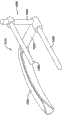
图1是设置在虚拟箱中的示例性心外膜夹的透视图;Figure 1 is a perspective view of an exemplary epicardial clip disposed in a dummy box;

图2A是图1中的心外膜夹的俯视图;Figure 2A is a top view of the epicardial clip in Figure 1;

图2B是图1中的心外膜夹的侧视图;Figure 2B is a side view of the epicardial clip in Figure 1;

图3A示出在想像的三维x-y-z坐标体系中图1的心外膜夹;Figure 3A shows the epicardial clip of Figure 1 in an imaginary three-dimensional x-y-z coordinate system;

图3B为图3A的三维x-y-z坐标体系中的x-y平面上的心外膜夹的二维图;3B is a two-dimensional view of the epicardial clip on the x-y plane in the three-dimensional x-y-z coordinate system of FIG. 3A;

图3C为图3A的三维x-y-z坐标体系中的x-z平面上的心外膜夹的二维图;3C is a two-dimensional view of the epicardial clip on the x-z plane in the three-dimensional x-y-z coordinate system of FIG. 3A;

图3D为图3A的三维x-y-z坐标体系中的y-z平面上的心外膜夹的二维图;3D is a two-dimensional view of the epicardial clip on the y-z plane in the three-dimensional x-y-z coordinate system of FIG. 3A;

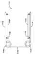
图4A为另一示例性心外膜夹的俯视图;Figure 4A is a top view of another exemplary epicardial clip;

图4B是图4A中的心外膜夹的侧视图;Figure 4B is a side view of the epicardial clip in Figure 4A;

图4C为沿图4A中的4C-4C线截取的心外膜夹的剖面图;Figure 4C is a cross-sectional view of the epicardial clip taken alongline 4C-4C in Figure 4A;

图5为所选择的心脏解剖特征的示意图;Fig. 5 is a schematic diagram of selected cardiac anatomical features;

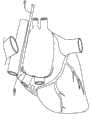
图6A为示出心外膜夹的示例性部分的心脏前部视图;Figure 6A is an anterior view of the heart showing an exemplary portion of an epicardial clip;

图6B为示出心外膜夹的示例性部分的心脏后部视图;Figure 6B is a posterior view of the heart showing an exemplary portion of an epicardial clip;

图7为示出心外膜夹的示例性部分的、心房除去后的心脏的心室部分的俯视图;7 is a top view of the ventricular portion of the heart after removal of the atria showing an exemplary portion of an epicardial clip;

图8A-8C为示出二尖瓣相对于心脏上的心外膜夹部分的平面的取向的示意图;8A-8C are schematic diagrams showing the orientation of the mitral valve relative to the plane of the epicardial clip portion on the heart;

图9-15示出示例性心外膜夹的其它实施方案和可选择的构造;9-15 illustrate other embodiments and alternative configurations of exemplary epicardial clips;

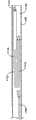
图16为另一心外膜夹的俯视图;Figure 16 is a top view of another epicardial clip;

图17为沿图16的17-17线截取的心外膜夹的侧视图;Figure 17 is a side view of the epicardial clip taken along line 17-17 of Figure 16;

图18为沿图16的18-18线截取的心外膜夹的侧视图;Figure 18 is a side view of the epicardial clip taken along line 18-18 of Figure 16;

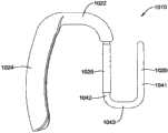
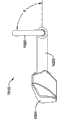
图19和20为再一示例性心外膜夹的透视图;19 and 20 are perspective views of yet another exemplary epicardial clip;

图21为图19和20所示的心外膜夹的俯视图;Figure 21 is a top view of the epicardial clip shown in Figures 19 and 20;

图21A为示出心外膜夹的示例性弯曲和尺寸的俯视图;Figure 21A is a top view showing exemplary curvature and dimensions of an epicardial clip;

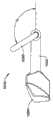
图22为具有旋转后的前部部分的图19和20所示心外膜夹的透视图;22 is a perspective view of the epicardial clip shown in FIGS. 19 and 20 with the anterior portion rotated;

图23A-23C为图19和20所示心外膜夹的侧视图,示出了前部部分各种可能的旋转后的位置;23A-23C are side views of the epicardial clip shown in FIGS. 19 and 20 showing various possible rotated positions of the anterior portion;

图24为其上设置有图19和20的心外膜夹的心脏的上面视图;Figure 24 is a top view of the heart with the epicardial clip of Figures 19 and 20 placed thereon;

图25-29为图19和20所示的心外膜夹的可选择的构造;Figures 25-29 are alternative configurations of the epicardial clip shown in Figures 19 and 20;

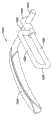
图30示出具有设置在后部部分上的垂悬物材料的图19和20的心外膜夹;Figure 30 shows the epicardial clip of Figures 19 and 20 with a pendant material disposed on the posterior portion;

图31-34示出图19和20的心外膜夹的进一步改进;Figures 31-34 show a further modification of the epicardial clip of Figures 19 and 20;

图35-38示出校准设备的示例性实施方案,其中该校准设备可以用于确定本文所公开的心外膜夹的正确大小、形状和/或取向;35-38 illustrate exemplary embodiments of calibration devices that may be used to determine the correct size, shape and/or orientation of the epicardial clips disclosed herein;

图39A和39B示出心外膜夹的另外实施方案;以及Figures 39A and 39B illustrate additional embodiments of epicardial clips; and

图40-44示出将心外膜夹定位在心脏上的示例性方法。40-44 illustrate an exemplary method of positioning an epicardial clip on the heart.

尽管可以对本发明中的各种改进和可选择的形式进行修改,但是在附图中通过例子的形式示出了特定的改进和可选择的形式,并且对其将要详细描述。然而,应该理解的是,这并不是要将发明内容局限于所描述的具体实施方案。相反,意图涵盖落在本发明精神和范围内的所有的改进、等同物、以及变化。Although various modifications and alternatives in the present invention can be modified, specific modifications and alternatives are shown by way of example in the drawings and will be described in detail. It should be understood, however, that the intention is not to limit the inventive subject matter to the particular embodiments described. On the contrary, the intention is to cover all modifications, equivalents, and variations falling within the spirit and scope of the invention.

具体实施方式Detailed ways

除非在权利要求书或本申请文件中的其它地方给出不同的定义,否则都应该使用下面所限定的术语的定义。Unless a different definition is given in the claims or elsewhere in this application document, the definitions of the terms defined below shall apply.

不管是否明确指出,本文假定所有的数值都用术语“约”来修饰。术语“约”通常是指这样的数值范围:本领域技术人员会考虑到该参考值的等同物(如,具有相同的功能或结果)。在多数情况下,术语“约”可以指包括取整数后为最接近的有效数字的数字。Whether expressly stated or not, it is assumed herein that all numerical values are modified by the term "about". The term "about" generally refers to a range of values that would be considered equivalent (eg, having the same function or result) to the referenced value by those skilled in the art. In most instances, the term "about" may be meant to include numbers rounded to the nearest significant figure.

由端点表示的数值范围包括该范围内的所有数值(例如,1至5包括1、1.5、2、2.75、3、3.80、4和5)。The recitations of numerical ranges by endpoints include all numbers within that range (eg, 1 to 5 includes 1, 1.5, 2, 2.75, 3, 3.80, 4, and 5).

虽然公开了一些与各种组成、特征和/或说明有关的合适的尺寸、范围和/或数值,但是本领域技术人员根据本发明公开会理解到所希望的尺寸、范围和/或数值可能偏离已经公开的那些尺寸、范围和/或数值。Although some suitable dimensions, ranges and/or values are disclosed in relation to various compositions, features and/or descriptions, those skilled in the art will understand from the present disclosure that the desired dimensions, ranges and/or values may deviate from Those dimensions, ranges and/or values have been disclosed.

如本说明书和随附的权利要求书中所用,单数形式“一”和“所述”包括复数对象,除非在其它地方明确地指出其含义。如本说明书和随附的权利要求书中所用,术语“或”通常包括“和/或”的意思,除非在其它地方明确地指出其含义。As used in this specification and the appended claims, the singular forms "a" and "the" include plural referents unless the meaning is clearly indicated otherwise. As used in this specification and the appended claims, the term "or" generally includes its meaning "and/or" unless its meaning is expressly indicated elsewhere.

如本说明书和随附的权利要求书中所用,在解剖学含义中,术语“前部”用来表示“朝前、在前面、或者前表面”。As used in this specification and the appended claims, the term "anterior" is used in an anatomical sense to mean "facing forward, at the front, or at the front surface."

如本说明书和随附的权利要求书中所用,在解剖学含义中,术语“后部”用来表示“朝后、在后面、或者后表面”。As used in this specification and the appended claims, the term "posterior" is used in an anatomical sense to mean "rearward, at the rear, or posterior surface".

如本说明书和随附的权利要求书中所用,在解剖学含义中,术语“之上”用来表示“上面、在上面、朝上、或者朝前头”。As used in this specification and the appended claims, the term "over" is used in an anatomical sense to mean "above, on, upward, or forward of".

如本说明书和随附的权利要求书中所用,在解剖学含义中,术语“之下”用来表示“下面、在下面、朝下、或者朝后头”。As used in this specification and the appended claims, the term "under" is used in an anatomical sense to mean "under, below, downward, or posteriorly".

如本说明书和随附的权利要求书中所用,在解剖学含义中,术语“侧面”用来表示“远离身体径向或中间平面或者中线的位置或方向,向侧面、或者侧表面”。As used in this specification and the appended claims, the term "lateral" is used in an anatomical sense to mean "a position or direction away from a radial or median plane or midline of the body, toward a side, or lateral surface".

下面的详细描述应参照附图,其中在附图中,不同图中相同的元件的编号相同。这些详细描述和附图(不局限于规格)描述了示例性实施方案并且不是要限定本发明的范围。所描述的示例性实施方案仅作为示意性。任意一个示例性实施方案中所选择的特征可以被并入其它的实施方案中,除非有相反的说明。In the following detailed description, reference should be made to the accompanying drawings, in which like elements in different drawings are numbered the same. The detailed description and drawings, which are not limiting in specification, describe exemplary embodiments and are not intended to limit the scope of the invention. The described exemplary embodiments are by way of illustration only. Selected features of any one exemplary embodiment can be incorporated into other embodiments unless stated to the contrary.

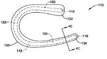
现在参见附图,图1示出了心外膜夹10。心外膜夹10被描绘在虚拟箱50中以进一步说明心外膜夹10的三维几何形状。另外,虚拟箱50中示出了两个虚拟平面53、55以进一步示出心外膜夹10的几何形状。心外膜夹10可以包括具有第一末端14和第二末端16的弯曲部件12。在一些实施方案中,弯曲部件12可以是线材、杆、棒、带等。在一些实施方案中,心外膜夹10可以由单一的连续线材形成,或者心外膜夹10可以包括多个相互连接的线材。弯曲部件12包括接近第一末端14的前部部分20、接近第二末端16的后部部分24、以及夹在前部部分20和后部部分24之间的侧面部分22。换句话说,侧面部分22位于部件12的前部部分20和后部部分24之间。如图1所示,在一些实施方案中,前部部分20可以包括笔直部分,后部部分24可以包括弯曲或弧形部分,以及/或者连接前部部分20和后部部分24的侧面部分22可以包括弯曲部分(如,螺旋部分)。在一些实施方案中,前部部分20可以包括弯曲部分并且/或者后部部分24可以包括笔直部分。可以选择部件12的各部分的形状(如弯曲部分)使得部件12的弯曲与心脏的大体形状吻合。在一些实施方案中,部件12可以由柔性材料形成,使得在医疗过程中部件12的弯曲可以根据需要而改变,以与患者心脏的解剖形状以及/或者心脏解剖区域周围的可允许变形相对应。在其它实施方案中,部件12可以由具有固定的弯曲度并且不容易弯曲成特别的非柔性或刚性材料形成。Referring now to the drawings, FIG. 1 shows anepicardial clip 10 . Theepicardial clip 10 is depicted in a virtual box 50 to further illustrate the three-dimensional geometry of theepicardial clip 10 . Additionally, twovirtual planes 53 , 55 are shown in the virtual box 50 to further illustrate the geometry of theepicardial clip 10 . Theepicardial clip 10 may include acurved member 12 having afirst end 14 and asecond end 16 . In some embodiments,curved member 12 may be a wire, rod, rod, ribbon, or the like. In some embodiments,epicardial clip 10 may be formed from a single continuous wire, orepicardial clip 10 may comprise a plurality of interconnected wires. Thecurved member 12 includes afront portion 20 proximate thefirst end 14 , arear portion 24 proximate thesecond end 16 , and aside portion 22 sandwiched between thefront portion 20 and therear portion 24 . In other words,side portion 22 is located betweenfront portion 20 andrear portion 24 ofcomponent 12 . As shown in FIG. 1 , in some embodiments, thefront portion 20 may include a straight portion, therear portion 24 may include a curved or arcuate portion, and/or aside portion 22 connecting thefront portion 20 and therear portion 24 Curved portions (eg, helical portions) may be included. In some embodiments, thefront portion 20 may include a curved portion and/or therear portion 24 may include a straight portion. The shape of portions of member 12 (eg, curved portions) may be selected such that the curvature ofmember 12 conforms to the general shape of the heart. In some embodiments,member 12 may be formed of a flexible material such that the curvature ofmember 12 may be changed as needed during a medical procedure to correspond to the anatomical shape of the patient's heart and/or allowable deformations around the anatomical region of the heart. In other embodiments,member 12 may be formed from a particularly inflexible or rigid material that has a fixed degree of curvature and does not bend easily.

部件12可以由任意的合适材料形成。例如,部件12可以由金属、金属合金、聚合物、金属-聚合物复合体、它们的组合等、或者任意其它合适的材料制得。合适的金属和金属合金的一些例子包括:不锈钢,如304V、304L和316L不锈钢;低碳钢;钛合金,包括α-β钛合金,如6AL-4V(如,UNS:R56400);镍-钛合金,如线弹性和/或超弹性镍钛诺;其它镍合金,如镍-铬-钼合金(如,UNS:N06625(如INCONEL

Figure BPA00001325007100071
625),UNS:N06022(如HASTELLOYC-22
Figure BPA00001325007100073
),UNS:N10276(如HASTELLOY
Figure BPA00001325007100074
C276
Figure BPA00001325007100075
),其它HASTELLOY合金等),镍-铜合金(如,UNS:N04400(如MONEL
Figure BPA00001325007100077
400、NICKELVAC
Figure BPA00001325007100078
400、等)),镍-钴-铬-钼合金(如,UNS:R30035(如MP35-N
Figure BPA00001325007100079
等)),镍-钼合金(如,UNS:N10665(如HASTELLOY
Figure BPA000013250071000710
ALLOY B2
Figure BPA000013250071000711
)),其它镍-铬合金,其它镍-钼合金,其它镍-钴合金,其它镍-铁合金,其它镍-铜合金,其它镍-钨合金,等;钴-铬合金;钴-铬-钼合金(如,UNS:R30003(如ELGILOY
Figure BPA000013250071000712
、PHYNOX
Figure BPA000013250071000713
,等));富含铂的不锈钢;钛合金;它们的组合;等等;或者任意其它的合适材料。Component 12 may be formed from any suitable material. For example,component 12 may be fabricated from metal, metal alloys, polymers, metal-polymer composites, combinations thereof, etc., or any other suitable material. Some examples of suitable metals and metal alloys include: stainless steels, such as 304V, 304L, and 316L stainless steels; mild steels; titanium alloys, including alpha-beta titanium alloys, such as 6AL-4V (e.g., UNS: R56400); nickel-titanium Alloys, such as linear elastic and/or superelastic Nitinol; other nickel alloys, such as nickel-chromium-molybdenum alloys (eg, UNS: N06625 (eg INCONEL
Figure BPA00001325007100071
625), UNS: N06022 (such as HASTELLOY C-22
Figure BPA00001325007100073
), UNS: N10276 (such as HASTELLOY
Figure BPA00001325007100074
C276
Figure BPA00001325007100075
), other HASTELLOY alloy, etc.), nickel-copper alloy (such as, UNS: N04400 (such as MONEL
Figure BPA00001325007100077
400、NICKELVAC
Figure BPA00001325007100078
400, etc.)), nickel-cobalt-chromium-molybdenum alloy (such as, UNS: R30035 (such as MP35-N
Figure BPA00001325007100079
etc.)), nickel-molybdenum alloy (such as, UNS: N10665 (such as HASTELLOY
Figure BPA000013250071000710
ALLOY B2
Figure BPA000013250071000711
)), other nickel-chromium alloys, other nickel-molybdenum alloys, other nickel-cobalt alloys, other nickel-iron alloys, other nickel-copper alloys, other nickel-tungsten alloys, etc.; cobalt-chromium alloys; cobalt-chromium-molybdenum alloys Alloy (such as, UNS: R30003 (such as ELGILOY
Figure BPA000013250071000712
、PHYNOX
Figure BPA000013250071000713
, etc.)); platinum-rich stainless steel; titanium alloys; combinations thereof; etc.; or any other suitable material.

合适的聚合物的一些例子可以包括:氟化乙烯丙烯(FEP)、聚甲醛(POM,例如,可得自DuPont的DELRIN)、聚醚嵌段酯、聚氨酯、聚丙烯(PP)、聚乙烯吡咯烷酮(PVC)、聚醚酯(如可得自DSM Engineering Plastics的ARNITEL)、醚或酯类共聚物(如丁烯/聚(亚烷基醚)邻苯二甲酸酯和/或其它聚酯弹性体,如可得自DuPont的HYTREL)、聚酰胺(如可得自Bayer的DURETHAN

Figure BPA000013250071000717
或可得自Elf Atochem的CRISTAMID
Figure BPA000013250071000718
)、弹性体聚酰胺、嵌段聚酰胺/醚、聚醚嵌段酰胺(PEBA,如商标名为PEBAX
Figure BPA000013250071000719
的市售品)、乙烯醋酸乙烯酯共聚物(EVA)、有机硅、聚乙烯(PE)、高密度聚乙烯、低密度聚乙烯、聚酯、聚对苯二甲酸丁二醇酯(PBT)、聚对苯二甲酸乙二醇酯(PET)、聚醚醚酮(PEEK)、聚亚酰胺(PI)、生物适应性聚合物、其它合适的材料、或者它们的化合物、组合物、聚合物/金属复合物,等。Some examples of suitable polymers may include: fluorinated ethylene propylene (FEP), polyoxymethylene (POM, e.g., DELRIN available from DuPont ), polyether block esters, polyurethanes, polypropylene (PP), polyvinylpyrrolidone (PVC), polyetheresters (such as ARNITEL available from DSM Engineering Plastics ), ether or ester copolymers (such as butene/poly(alkylene ether) phthalate and/or other polyester elastomers such as HYTREL available from DuPont ), polyamides (such as DURETHAN available from Bayer
Figure BPA000013250071000717
or CRISTAMID available from Elf Atochem
Figure BPA000013250071000718
), elastomeric polyamide, block polyamide/ether, polyether block amide (PEBA, such as trade name PEBAX
Figure BPA000013250071000719
commercially available), ethylene vinyl acetate (EVA), silicone, polyethylene (PE), high-density polyethylene, low-density polyethylene, polyester, polybutylene terephthalate (PBT) , polyethylene terephthalate (PET), polyether ether ketone (PEEK), polyimide (PI), biocompatible polymers, other suitable materials, or their compounds, compositions, polymers / metal complexes, etc.

图2A为相对于图1所示夹具10的取向而截取的夹具10的俯视图。从上往下直接观看图1所示虚拟箱50的顶部52并显示出想像平面53时获得图2A所示视图。如图2A所示,当从该方向观察时,夹具10通常可以具有U型或C型。夹具10可以被成型为使得在部件12的第一末端14与部件12的第二末端16之间,夹具10在前部部分20与后部部分24之间的距离最近。如后文所讨论的那样,第一末端14与第二末端16之间的距离可以确定二尖瓣的最终前后直径。前部部分20可以基本上是笔直的,因此能够固定在心脏的横窦中。后部部分24可以是弓形的,其对应于心脏后心室壁的半圆形弯曲。侧面部分22可以具有围绕心脏左侧的螺旋状弯曲,该弯曲使得横窦中的前部部分20以及后部部分24位于心脏的后部,如心脏的房室沟处或房室沟下面或者心包斜窦中。在一项实施方案中,侧面部分22的弯曲的半径可以为约5毫米至约70毫米,或者为约30毫米至约46毫米,例如为约10毫米、约20毫米、约30毫米、约40毫米、约50毫米、约60毫米、约70毫米,或者为其它所需的弯曲半径,使得侧面部分22可以被正确地设置在心脏侧面周围。在一些实施方案中,侧面部分22可以被安置在心脏左心房附件的周围、上面和/或下面。在其它实施方案中,侧面部分22可以被安置在心脏左心房的上面。FIG. 2A is a top view ofjig 10 taken relative to the orientation ofjig 10 shown in FIG. 1 . The view shown in FIG. 2A is obtained looking directly from above at the top 52 of the virtual box 50 shown in FIG. 1 and showing theimaginary plane 53 . As shown in FIG. 2A , thejig 10 may generally have a U-shape or a C-shape when viewed from this direction. Theclamp 10 may be shaped such that the distance between thefront portion 20 and therear portion 24 of theclamp 10 is closest between thefirst end 14 of thecomponent 12 and thesecond end 16 of thecomponent 12 . As discussed below, the distance between thefirst end 14 and thesecond end 16 can determine the final anterior-posterior diameter of the mitral valve. Theanterior portion 20 may be substantially straight, thereby enabling fixation in the transverse sinus of the heart.Posterior portion 24 may be arcuate, which corresponds to the semicircular curvature of the posterior ventricular wall of the heart. Thelateral portion 22 may have a helical curvature around the left side of the heart such that theanterior portion 20 in the transverse sinus and theposterior portion 24 are located at the back of the heart, such as at or below the atrioventricular groove of the heart or the pericardium In the oblique sinus. In one embodiment, the radius of curvature of theside portion 22 may be from about 5 millimeters to about 70 millimeters, or from about 30 millimeters to about 46 millimeters, such as about 10 millimeters, about 20 millimeters, about 30 millimeters, about 40 millimeters mm, about 50 mm, about 60 mm, about 70 mm, or other desired radius of curvature so that theside portion 22 can be properly positioned around the sides of the heart. In some embodiments,side portion 22 may be positioned around, above and/or below the left atrial appendage of the heart. In other embodiments,side portion 22 may be positioned over the left atrium of the heart.

图2B为相对于图1所示夹具10的取向而截取的夹具10的侧视图。直接观看图1所示虚拟箱50的前侧54并显示出想像平面53和55时获得图2B所示视图。如图2B所示,前部部分20可以位于想像平面中并且后部部分24可以位于想像平面中。后部部分24的想像平面可以与前部部分20的想像平面成锐角。在一些实施方案中,侧面部分的弯曲(如侧面部分的螺旋几何形状)可以控制前部部分20与后部部分24之间的角度θ。例如,在一些实施方案中,角度θ可以为约5度至约20度,例如为约5度、约10度、约15度、约20度、或者任意其它合适的角度。因此,夹具10的三维构造是指夹具10不必处于单一的想像平面中。FIG. 2B is a side view ofjig 10 taken relative to the orientation ofjig 10 shown in FIG. 1 . The view shown in FIG. 2B is obtained looking directly at the front side 54 of the virtual box 50 shown in FIG. 1 and showingimaginary planes 53 and 55 . As shown in FIG. 2B , thefront portion 20 may lie in an imaginary plane and therear portion 24 may lie in an imaginary plane. The imaginary plane of therear portion 24 may form an acute angle with the imaginary plane of thefront portion 20 . In some embodiments, the curvature of the side portions (eg, the helical geometry of the side portions) can control the angle θ between thefront portion 20 and therear portion 24 . For example, in some embodiments, angle Θ may be from about 5 degrees to about 20 degrees, such as about 5 degrees, about 10 degrees, about 15 degrees, about 20 degrees, or any other suitable angle. Thus, the three-dimensional configuration of thejig 10 means that thejig 10 does not have to lie in a single imaginary plane.

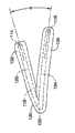
图3A-3D示出了位于坐标体系中的夹具10,该坐标体系具有原点O、从原点O延伸的x轴、从原点O延伸并且与x轴垂直的y轴、以及从原点O延伸并且与x轴和y轴均垂直的z轴。图3A示出了在三维x-y-z坐标体系中的夹具10。图3B-3D示出了分别在x-y坐标体系、x-z坐标体系和y-z坐标体系中的夹具10的二维视图。图3B为直接观看x-y面(即,穿过x轴和y轴的平面)时的视图。图3C为直接观看x-z面(即,穿过x轴和z轴的平面)时的视图。图3D为直接观看y-z面(即,穿过y轴和z轴的平面)时的视图。3A-3D show thefixture 10 in a coordinate system having an origin O, an x-axis extending from the origin O, a y-axis extending from the origin O and perpendicular to the x-axis, and a y-axis extending from the origin O and The z-axis is perpendicular to both the x-axis and the y-axis. Figure 3A shows thefixture 10 in a three-dimensional x-y-z coordinate system. 3B-3D show two-dimensional views of thefixture 10 in an x-y coordinate system, an x-z coordinate system, and a y-z coordinate system, respectively. FIG. 3B is a view looking directly at the x-y plane (ie, the plane passing through the x-axis and the y-axis). FIG. 3C is a view looking directly at the x-z plane (ie, the plane passing through the x-axis and the z-axis). FIG. 3D is a view looking directly at the y-z plane (ie, the plane passing through the y-axis and the z-axis).

如在部件12的第一末端14位于原点O的坐标体系中所示,前部部分20沿x轴在x方向(如,正的x方向)上延伸。前部部分20可以位于该坐标体系的x-y面中。可以具有弯曲(如螺旋弯曲)的侧面部分22从前部部分20延伸,并且侧面部分22可以在前部部分20与后部部分24之间在z方向(如,负的z方向)上产生坐标变化。后部部分24从侧面部分22延伸并且在x方向(如,负的x方向)上产生坐标变化、在y方向(如,负的y方向)上产生坐标变化以及在z方向(如,负的z方向)上产生坐标变化。因此,后部部分24不位于坐标体系的x-y平面、x-z平面或y-z平面中。这样,部件12可以包括这样一些元件,所述元件在x方向、y方向和z方向中均延伸,并且部件12不位于单一一个平面中。在一些实施方案中,从前部部分20延伸的侧面部分22可以包括沿y方向(如,正的y方向)延伸的笔直部分以及延伸至后部部分的弯曲部分。Front portion 20 extends along the x-axis in an x-direction (eg, a positive x-direction), as shown in a coordinate system in whichfirst end 14 ofmember 12 is at origin O. Thefront portion 20 may lie in the x-y plane of this coordinate system. Extending from thefront portion 20 is aside portion 22, which may have a curvature (e.g., a helical curvature), and theside portion 22 may produce a coordinate change in the z-direction (e.g., a negative z-direction) between thefront portion 20 and therear portion 24. . Therear portion 24 extends from theside portion 22 and produces a coordinate change in the x-direction (e.g., the negative x-direction), a coordinate change in the y-direction (e.g., the negative y-direction), and a coordinate change in the z-direction (e.g., the negative y-direction). Coordinate changes occur in the z direction). Accordingly, therear portion 24 does not lie in the x-y plane, x-z plane or y-z plane of the coordinate system. Thus,part 12 may comprise elements that extend in each of the x-direction, y-direction and z-direction, andpart 12 does not lie in a single plane. In some embodiments, theside portions 22 extending from thefront portion 20 may include straight portions extending in the y-direction (eg, the positive y-direction) and curved portions extending to the rear portion.

图4A和4B示出心外膜夹110的另一实施方案。与图1的弯曲部件112相似,心外膜夹110可以包括弯曲部件12(也参见图4C),如线材或带。弯曲部件112可以与图1的弯曲部件112具有基本上相同的形状和弯曲,因此,不必对部件112的弯曲进行额外的讨论。Another embodiment of anepicardial clip 110 is shown in FIGS. 4A and 4B . Similar tocurved member 112 of FIG. 1 ,epicardial clip 110 may include curved member 12 (see also FIG. 4C ), such as a wire or a strap.Curved member 112 may have substantially the same shape and curvature ascurved member 112 of FIG. 1 , and thus, no additional discussion of the curvature ofmember 112 is necessary.

如图4C(其为夹具110的穿过图4A中的线4C-4C的剖面)所示,夹具110包括弯曲部件112,该弯曲部件112被外部覆层130包围或者裹在外部覆层130中。在一些实施方案中,外部覆层130可以覆盖前部部分20、后部部分24和/或侧面部分22中的一者或多者。例如,外部覆层130可以覆盖后部部分24和侧面部分22而前部部分20未被裹在外部覆层130中。在一些实施方案中,外部覆层130可以为防止创伤的、可生物吸收的并且/或者生物适应性的覆层。例如,在一些实施方案中,外部覆层130可以为顺应材料,例如遍布有聚合物的成型品,如遍布有硅酮的成型品。外部覆层130(其可以至少部分地由顺应材料形成)可以更均匀地将应力从部件112分布至心脏表面,防止设置在心脏上的夹具110的侧面移动,并且/或者提供用于将夹具110固定到心脏上的区域。例如,在一些实施方案中,外部覆层130可以分布夹紧力以避免心肌层和/或心外膜上的动脉和/或静脉堵塞。在一些实施方案中,外部覆层130可以提供充分的扭转挠性,从而使得夹具110与心脏的轮廓相适应。As shown in FIG. 4C , which is a section ofjig 110 throughline 4C-4C in FIG. 4A ,jig 110 includes acurved member 112 that is surrounded by or encased in anouter cladding 130. . In some embodiments, theouter covering 130 may cover one or more of thefront portion 20 , therear portion 24 , and/or theside portions 22 . For example, theouter covering 130 may cover therear portion 24 and theside portions 22 without thefront portion 20 being encased in theouter covering 130 . In some embodiments, theouter covering 130 may be an atraumatic, bioabsorbable and/or biocompatible covering. For example, in some embodiments, theouter cover 130 may be a compliant material, such as a polymer over molding, such as a silicone over molding. Outer coating 130 (which may be formed at least in part from a compliant material) may more evenly distribute stress fromcomponent 112 to the surface of the heart, prevent sideways movement ofclip 110 disposed on the heart, and/or provide area fixed to the heart. For example, in some embodiments, theouter coating 130 can distribute clamping forces to avoid occlusion of arteries and/or veins on the myocardium and/or epicardium. In some embodiments, theouter coating 130 can provide sufficient torsional flexibility such that theclip 110 conforms to the contours of the heart.

外部覆层130在前部部分120上可以具有圆形或球形部分132,并且在后部部分124上具有平坦部分134。如后文所讨论的那样,球形部分132可以防止当夹具110设置在心脏上时发生侧面移动,并且可以在横窦中更均匀地分布应力。在一些实施方案中,可以将具有球形部分132的前部部分120成型为保护大血管(如主动脉、肺动脉干、上腔大静脉)的血液动力学并且帮助前部部分120保持在横窦中。可以形成平坦部分134以对应于心脏的轮廓并且/或者可以更均匀地分布夹具110施加在心脏后部的力。例如,平坦部分134可以与心脏心外膜表面上的血管周围相一致,从而避免血管堵塞。Theouter cladding 130 may have a rounded orspherical portion 132 on thefront portion 120 and aflat portion 134 on therear portion 124 . As discussed below,spherical portion 132 can prevent lateral movement whenclamp 110 is placed on the heart and can more evenly distribute stress in the transverse sinus. In some embodiments,anterior portion 120 withbulbous portion 132 can be shaped to protect the hemodynamics of large vessels (e.g., aorta, pulmonary trunk, superior vena cava) and to help maintainanterior portion 120 in the transverse sinus .Flat portion 134 may be formed to correspond to the contour of the heart and/or may more evenly distribute the force exerted byclamp 110 on the back of the heart. For example,flat portion 134 may conform to the periphery of blood vessels on the epicardial surface of the heart, thereby avoiding vascular occlusion.

如图4C所示,在一些实施方案中,外部覆层130可以包括在织物护套133中以及/或者包裹在织物护套133中。例如,在一些实施方案中,根据需要,织物护套133可以为PTFE材料、聚酯编织织物、聚酯丝绒、聚丙烯毡、编织或编织的织物、非编织织物、多孔材料、或者其它织物。织物护套133可以促进心脏心外膜表面上的组织生长,可以将组织生长提供为织物护套133的空隙,以及/或者提供充足的摩擦力以保持夹具110与心脏接触并防止已设置在心脏上的设备移动。其中和/或其上的组织生长可以使得夹具110保持在心脏中的所需位置处并防止腐蚀。As shown in FIG. 4C , in some embodiments, theouter cover 130 may be included in and/or wrapped in afabric sheath 133 . For example, in some embodiments,fabric sheath 133 may be a PTFE material, polyester woven fabric, polyester velor, polypropylene felt, woven or woven fabric, non-woven fabric, porous material, or other fabric, as desired. Thefabric sheath 133 can promote tissue growth on the epicardial surface of the heart, can provide tissue growth as a void for thefabric sheath 133, and/or provide sufficient friction to keep theclamp 110 in contact with the heart and prevent theclamp 110 from being placed in the heart. device moves on. Tissue growth in and/or thereon may keepclip 110 in a desired position in the heart and prevent corrosion.

在一些实施方案中,夹具110可以还包括药物洗脱涂层、或者作为外部覆层130的替代物而具有药物洗脱涂层。药物洗脱涂层可以为治疗药剂在特定的期间内的控制释放。治疗药剂可以为可提供所需效果的任意医用药剂。合适的治疗药剂包括药物、遗传物质、以及生物学材料。一些可被负载在药物洗脱涂层中的合适的治疗药剂包括但不限于抗生素、抗菌剂、抗氧化剂、抗心律失常药、细胞生长因子、免疫抑制剂(如他克莫司、依维莫司以及雷帕霉素(西罗莫司))、治疗性抗体、伤口愈合剂、治疗性转基因构建体、肽类、蛋白质、细胞外基质成分、甾体和非甾体消炎药、抗增生药(如甾体类)、维生素和再狭窄抑制药,如Taxol

Figure BPA00001325007100101
、紫杉醇(即,紫杉醇、紫杉醇类似物、或者紫杉醇衍生物、以及它们的混合物)。In some embodiments,clip 110 may also include or have a drug eluting coating instead ofouter coating 130 . Drug eluting coatings can provide controlled release of therapeutic agents over a specified period of time. A therapeutic agent can be any medical agent that provides a desired effect. Suitable therapeutic agents include drugs, genetic material, and biological material. Some suitable therapeutic agents that can be loaded into drug eluting coatings include, but are not limited to, antibiotics, antibacterials, antioxidants, antiarrhythmics, cellular growth factors, immunosuppressants (e.g., tacrolimus, everolimus, and rapamycin (sirolimus), therapeutic antibodies, wound healing agents, therapeutic transgenic constructs, peptides, proteins, extracellular matrix components, steroidal and nonsteroidal anti-inflammatory drugs, antiproliferative drugs (such as steroids), vitamins, and restenosis inhibitors such as Taxol
Figure BPA00001325007100101
, paclitaxel (ie, paclitaxel, paclitaxel analogs, or paclitaxel derivatives, and mixtures thereof).

图4A和4B分别为夹具110的在与图2A和2B所示的夹具10的取向相同的取向上的俯视图和侧视图。因此,如图4A所示,夹具110可以基本上为U型或C型。在一些实施方案中,在部件112的第一末端114与部件112的第二末端116之间,夹具10在前部部分120与后部部分124之间的距离最近。第一末端114与第二末端116之间的距离可以确定二尖瓣的最终前后直径。4A and 4B are top and side views, respectively, ofjig 110 in the same orientation asjig 10 shown in FIGS. 2A and 2B . Thus, as shown in FIG. 4A, thejig 110 may be substantially U-shaped or C-shaped. In some embodiments, the distance between thefront portion 120 and therear portion 124 of thejig 10 is closest between thefirst end 114 of themember 112 and thesecond end 116 of themember 112 . The distance between thefirst end 114 and thesecond end 116 may determine the final anterior-posterior diameter of the mitral valve.

如图4B所示,前部部分120可以位于想像平面中并且后部部分124可以位于想像平面中。后部部分124的想像平面可以与前部部分120的想像平面成锐角θ。侧面部分122的几何形状(如螺旋几何形状)可以控制前部部分120与后部部分124之间的角度θ。因此,侧面部分122的弯曲(如螺旋弯曲)可以确保前部部分120正确地位于横窦中同时后部部分124正确地位于心脏的后部,如心脏的房室沟处或房室沟下面或者心包斜窦中。As shown in FIG. 4B , thefront portion 120 may lie in an imaginary plane and therear portion 124 may lie in an imaginary plane. The imaginary plane of therear portion 124 may form an acute angle θ with the imaginary plane of theanterior portion 120 . The geometry of theside portion 122 , such as the helical geometry, can control the angle θ between thefront portion 120 and therear portion 124 . Thus, the curvature (e.g., helical curvature) of theside portions 122 can ensure that theanterior portion 120 is correctly positioned in the transverse sinus while theposterior portion 124 is correctly positioned at the back of the heart, such as at or below the atrioventricular groove of the heart or In the oblique sinus of the pericardium.

图5示出了作为人心脏的心脏H。从前侧稍高的位置来观看心脏H。心脏H的室包括左心室LV、左心房LA、右心室RV和右心房RA。还示出了肺动脉干PT、主动脉A、上腔大静脉SVC、右肺静脉RPV、左肺静脉LPV、以及左心房附件LAA。图5还示出了横窦TS。横窦TS为心包P与心脏H的心外膜表面之间的心包腔,位于主动脉A和肺动脉干PT之后以及左心房和上腔大静脉SVC之前。Fig. 5 shows a heart H which is a human heart. The heart H is viewed from a slightly higher position on the front side. The chambers of the heart H include a left ventricle LV, a left atrium LA, a right ventricle RV, and a right atrium RA. Also shown are pulmonary trunk PT, aorta A, superior vena cava SVC, right pulmonary vein RPV, left pulmonary vein LPV, and left atrial appendage LAA. Figure 5 also shows the transverse sinus TS. The transverse sinus TS is the pericardial cavity between the pericardium P and the epicardial surface of the heart H, posterior to the aorta A and pulmonary trunk PT and anterior to the left atrium and superior vena cava SVC.

也示出了将围心囊或心包P(其为覆盖心脏H的心外膜表面的组织膜)从图5的心脏H除去后的情况,以进一步说明心脏H的重要的解剖结构。斜窦OS为心脏H后部(形成于心包P与心脏H的心外膜表面之间)的盲隐窝(如,死路)。斜窦OS通常位于右肺静脉RPV与左肺静脉LPV,具有下腔静脉IVC(其位于斜窦OS的右部)的胸部。只有两层浆膜心包将横窦TS和斜窦OS分开。The pericardial sac or pericardium P (which is the tissue membrane covering the epicardial surface of the heart H) is also shown after removal from the heart H of FIG. 5 to further illustrate the important anatomy of the heart H. The oblique sinus OS is a blind recess (eg, dead end) in the posterior part of the heart H (formed between the pericardium P and the epicardial surface of the heart H). The oblique sinus OS is usually located in the right RPV and left pulmonary vein LPV, chest with the inferior vena cava IVC which is located to the right of the oblique sinus OS. Only two layers of the serosa pericardium separate the transverse TS from the oblique OS.

在医疗过程中夹具10可设置在心脏H的心外膜表面。例如,在一些实施方案中,在不停跳心脏上述中,夹具10可以被安装在心脏H上,而无需心/肺体外循环机。例如,夹具10可通过开胸手术(胸骨切开术)或外侧切口而植入到心脏H上。在一些实施方案中,夹具10可通过侵害性小的内窥镜途径而被设置到心脏H上。Clip 10 may be placed on the epicardial surface of heart H during a medical procedure. For example, in some embodiments, clamp 10 may be mounted on heart H without a heart/lung extracorporeal bypass machine in a beating heart setting. For example,clip 10 may be implanted on heart H through open chest surgery (sternotomy) or lateral incision. In some embodiments,clip 10 may be placed on heart H through a less invasive endoscopic approach.

例如,在胸骨切开术中,可以进入胸腔以直接观察夹具10在跳动的心脏H上的放置。可以切开心包P以接近心包P与心脏H的心外膜表面之间的心包腔。在接近心包腔时,夹具10可以被正确地设置在心脏H的心外膜表面上。前部部分20可以设置在位于主动脉A和肺动脉干PT之后且左心房和上腔大静脉SVC之前的横窦TS中。因此,部件12的第一末端14可以位于横窦TS中。后部部分24可设置在心脏H的后侧,如房室沟AVG处或房室沟AVG下面(如图6B所示)或者心包斜窦OS中。这样,部件12的第二末端16可以位于房室沟AVG处或房室沟AVG下面或者心包斜窦OS中。在一些实施方案中,后部部分24可以设置在心脏H后侧的房室沟下面。侧面部分22可以围绕心脏H的左侧面延伸,使得前部部分20正确地设置在横窦TS中同时后部部分24正确地设置在心脏H的后侧,如房室沟AVG处或房室沟AVG下面或者心包斜窦OS中。在一些实施方案中,侧面部分22可以在左心房附件LAA之下的位置围绕心脏H延伸。但是,在其它的实施方案中,侧面部分22可以在左心房附件LAA之上或者左心房LA上方的位置围绕心脏H延伸以将前部部分20和后部部分24相连。For example, during a sternotomy, the chest cavity can be accessed to directly observe the placement of theclamp 10 on the beating heart H. FIG. The pericardium P may be cut to access the pericardial cavity between the pericardium P and the epicardial surface of the heart H. Theclip 10 can be correctly placed on the epicardial surface of the heart H when approaching the pericardial cavity. Theanterior portion 20 may be disposed in the transverse sinus TS posterior to the aorta A and pulmonary trunk PT and anterior to the left atrium and superior vena cava SVC. Thus, thefirst end 14 of thecomponent 12 may be located in the transverse sinus TS. Theposterior portion 24 may be disposed on the posterior side of the heart H, such as at or below the atrioventricular groove AVG (as shown in FIG. 6B ) or in the oblique pericardial sinus OS. Thus, thesecond end 16 of themember 12 may be located at or below the atrioventricular groove AVG or in the oblique pericardial sinus OS. In some embodiments, theposterior portion 24 may be positioned below the atrioventricular groove on the posterior side of the heart H. Theside portion 22 may extend around the left side of the heart H such that theanterior portion 20 is properly positioned in the transverse sinus TS while theposterior portion 24 is properly positioned on the posterior side of the heart H, such as at the atrioventricular groove AVG or atrioventricular Sulcus below the AVG or in the pericardial oblique sinus OS. In some embodiments,side portion 22 may extend around heart H at a location below the left atrial appendage LAA. However, in other embodiments,side portion 22 may extend around heart H at a location above left atrial appendage LAA or above left atrium LA to connectanterior portion 20 andposterior portion 24 .

当夹具10被正确地设置时,夹具10可以位于心脏H的心外膜表面、心包P的内部。因此,设置夹具10时可以不需要穿过心脏进入心脏的一个或多个室以及/或者可以不需要使夹具10与位于心脏各室内的血液接触。通过在心外膜表面(心脏H内部的外部)上放置夹具10,避免了与手术过程(其中需要接近心脏H的一个或多个室)有关的并发症。另外,与心内直视手术或需要通过脉管系统而接近心脏的手术过程相比,完成手术过程所需要的时间可以大大减少。Theclip 10 may be located on the epicardial surface of the heart H, inside the pericardium P, when theclip 10 is properly set. Thus, theclip 10 may not need to be placed through the heart into one or more chambers of the heart and/or theclip 10 may not need to come into contact with blood located within the various chambers of the heart. By placingclamp 10 on the epicardial surface (outside of the interior of heart H), complications associated with surgical procedures in which access to one or more chambers of heart H is required are avoided. Additionally, the time required to complete a surgical procedure can be greatly reduced compared to open heart surgery or surgical procedures that require access to the heart through the vasculature.

在一些实施方案中,在医疗过程中,部件12的第一末端14与第二末端16之间的距离可以改变以调节二尖瓣MV小叶的接合。通过调节部件12的第一末端14与第二末端16之间的距离,或者调节部件12的弯曲度,施加到心脏H壁上的力的量可以改变从而获得所需的对二尖瓣MV的反应。在一些实施方案中,最初可以使用校准设备以确定所需的夹具10的弯曲度,然后可以选择适当弯曲度的夹具10,或者可以使夹具10形成为合适的弯曲度以获得对二尖瓣MV的所需结果。可以获得超声波心动描记图像以确定夹具10的最佳的或者所需的位置和/或弯曲度。In some embodiments, the distance between thefirst end 14 and thesecond end 16 of themember 12 can be changed to adjust the coaptation of the mitral valve MV leaflets during a medical procedure. By adjusting the distance between thefirst end 14 and thesecond end 16 of themember 12, or adjusting the curvature of themember 12, the amount of force applied to the wall of the heart H can be varied to obtain the desired force on the mitral valve MV. reaction. In some embodiments, a calibration device may be used initially to determine the desired curvature of theclip 10, and then aclip 10 of the appropriate curvature may be selected, or theclip 10 may be formed to the appropriate curvature to achieve optimal alignment of the mitral valve MV. the desired result. Echocardiographic images may be obtained to determine an optimal or desired position and/or curvature of theclamp 10 .

图6A为心脏H的前部视图,其中夹具10设置在心脏H的心外膜表面。如图6A所示,夹具10的前部部分20设置在位于主动脉A和肺动脉干PT之后且左心房和上腔大静脉SVC之前的横窦TS中。侧面部分22可以在左心房附件LAA之下的位置围绕心脏H延伸。在其它的实施方案中,侧面部分22可以在左心房附件LAA之上或者左心房LA上方的位置围绕心脏H延伸。FIG. 6A is an anterior view of a heart H with theclamp 10 placed on the epicardial surface of the heart H. FIG. As shown in Figure 6A, theanterior portion 20 of theclip 10 is placed in the transverse sinus TS posterior to the aorta A and pulmonary trunk PT and anterior to the left atrium and superior vena cava SVC. Theside portions 22 may extend around the heart H at a location below the left atrial appendage LAA. In other embodiments, thelateral portion 22 may extend around the heart H at a location above the left atrial appendage LAA or above the left atrium LA.

图6B为心脏H的后部视图,其中夹具10设置在心脏H的心外膜表面。如图6B所示,夹具10的后部部分24设置在心脏H后侧的房室沟AVG下面。可以设置后部部分24使得其正好位于旋动脉CX下面。在其它实施方案中,可以设置后部部分24使得其正好位于旋动脉CX上面。FIG. 6B is a posterior view of a heart H with theclip 10 placed on the epicardial surface of the heart H. FIG. As shown in FIG. 6B , theposterior portion 24 of thejig 10 is placed under the atrioventricular groove AVG on the posterior side of the heart H. As shown in FIG. Theposterior portion 24 may be positioned so that it is located just below the circumflex artery CX. In other embodiments, theposterior portion 24 may be positioned such that it lies just above the circumflex artery CX.

当夹具10被正确设置(其中前部部分20位于横窦TS中并且后部部分24位于斜窦OS中)时,夹具10可以对心脏H壁施加向里的压力。夹具10所施加的向里的压力可以改变位于左心房LA和左心室LV之间的二尖瓣环的几何形状,由此减少了穿过二尖瓣MV的前后距离以及/或者穿过二尖瓣MV的隔外侧距离。例如可以通过超声波心动描记图像来确定合适的向里的压力以优化二尖瓣MV的功能性,从而降低或消除二尖瓣反流。When theclamp 10 is properly positioned (with theanterior portion 20 in the transverse sinus TS and theposterior portion 24 in the oblique sinus OS), theclamp 10 can apply inward pressure to the wall of the heart H. The inward pressure applied by theclip 10 can change the geometry of the mitral annulus between the left atrium LA and the left ventricle LV, thereby reducing the anterior-posterior distance across the mitral valve MV and/or the distance across the mitral valve. The septum-lateral distance of the valve MV. For example, echocardiographic images can be used to determine the appropriate inward pressure to optimize the functionality of the mitral MV to reduce or eliminate mitral regurgitation.

图7为心房去除后的心脏H的心室部分的俯视图。由于心房被除去了,可以清楚地看到位于左心房LA和左心室LV之间的二尖瓣MV。图7还示出了位于右心房RA和右心室RV之间的三尖瓣TV、以及导向主动脉A的主动脉瓣AV和导向肺动脉干PT的肺动脉瓣PV。如图7所示,二尖瓣MV包括两个小叶,即前叶AL和后叶PL。示出的是在心脏收缩期二尖瓣MV关闭的状态。由于夹具10可以不位于二尖瓣MV平面内,图8中以虚线示出了夹具10。FIG. 7 is a top view of the ventricular portion of heart H after removal of the atrium. With the atria removed, the mitral valve MV can be clearly seen between the left atrium LA and the left ventricle LV. Figure 7 also shows the tricuspid valve TV located between the right atrium RA and the right ventricle RV, and the aortic valve AV leading to the aorta A and the pulmonary valve PV leading to the pulmonary trunk PT. As shown in FIG. 7, the mitral valve MV includes two leaflets, an anterior leaflet AL and a posterior leaflet PL. Shown is the closed state of the mitral valve MV during systole. Since theclip 10 may not lie in the plane of the mitral valve MV, theclip 10 is shown in phantom in FIG. 8 .

如图7所示,当夹具10被正确地放置在心脏周围,夹具10的形状可以使二尖瓣MV的前后尺寸减少。换句话说,夹具10可以促进二尖瓣MV的后叶PL向前叶AL靠近,使得二尖瓣MV的前叶和后叶更好地接触(接合),这可以降低或消除二尖瓣反流。例如,夹具10的后部部分24可以推向左心室LV的心室壁以改变二尖瓣MV环的距离。因此,如图7所示,包含夹具10可以使得后叶PL与前叶AL在心脏收缩期更充分地接触以降低或防止逆行血液流过二尖瓣,从而提高了心脏的效率。在医疗过程中,可以获得超声波心动描记图像以确定夹具10的最佳的或者所需的位置和/或弯曲度,从而获得二尖瓣MV环的合适的前后尺寸(距离)和/或隔外侧尺寸(距离)以最大程度地减小和/或消除二尖瓣反流。As shown in FIG. 7, when theclip 10 is properly placed around the heart, the shape of theclip 10 can reduce the anterior-posterior dimension of the mitral valve MV. In other words, theclip 10 can promote the approach of the posterior leaflet PL of the mitral valve MV to the anterior leaflet AL, so that the anterior leaflet and the posterior leaflet of the mitral valve MV can better contact (join), which can reduce or eliminate mitral valve regurgitation. flow. For example, theposterior portion 24 of theclip 10 may be pushed against the ventricular wall of the left ventricle LV to change the distance of the mitral valve MV annulus. Thus, as shown in FIG. 7, the inclusion ofclip 10 may allow more adequate contact of the posterior leaflet PL with the anterior leaflet AL during systole to reduce or prevent retrograde blood flow through the mitral valve, thereby increasing the efficiency of the heart. During a medical procedure, echocardiographic images may be obtained to determine the optimal or desired position and/or curvature of theclamp 10 to obtain the appropriate anterior-posterior dimension (distance) and/or lateral septum of the mitral MV annulus. size (distance) to minimize and/or eliminate mitral regurgitation.

图8A-8C示出了:当夹具10的前部部分20位于横窦TS中并且夹具10的后部部分24位于心脏H的后侧(如房室沟处或房室沟下面)时,二尖瓣MV平面取向时的夹具10。如前所述,二尖瓣MV位于想像平面(图8A-8C中为平面90)中。当被设置在心脏H的心外膜表面上时,前部部分20在二尖瓣MV平面上方延伸并且后部部分24在二尖瓣MV平面下方延伸。这样,前部部分20和后部部分24都不位于二尖瓣MV的同一平面内。另外,夹具10的第一末端14与夹具10的第二末端16之间的虚拟线不位于二尖瓣MV的平面内。如图8A-8C所示,二尖瓣MV的平面横穿夹具10的侧面部分22。8A-8C show that when theanterior portion 20 of thejig 10 is positioned in the transverse sinus TS and theposterior portion 24 of thejig 10 is positioned on the posterior side of the heart H (such as at or below the atrioventricular groove), the twoClamp 10 with the cusp MV in planar orientation. As previously mentioned, the mitral valve MV lies in an imaginary plane (plane 90 in FIGS. 8A-8C ). When positioned on the epicardial surface of the heart H, theanterior portion 20 extends above the plane of the mitral valve MV and theposterior portion 24 extends below the plane of the mitral valve MV. In this way, neither theanterior portion 20 nor theposterior portion 24 lies in the same plane of the mitral valve MV. Additionally, the imaginary line between thefirst end 14 of theclip 10 and thesecond end 16 of theclip 10 does not lie in the plane of the mitral valve MV. As shown in FIGS. 8A-8C , the plane of the mitral valve MV traverses theside portion 22 of theclip 10 .

图9至15示出了具有各种改变和其它特征的心外膜夹的可选择构造的其它实施方案。图9所示心外膜夹210中,在弯曲部件212的前部部分220中包括额外的或者第二弯曲240。第二弯曲240可以在前部弯曲,从而当前部部分220位于主动脉A后的横窦TS中时第二弯曲240在主动脉A周围伸出。这样,第二弯曲240可以有助于获得更好的设备稳定性以及/或者保持在横窦TS中,防止夹具210用于心脏H的过程中夹具210发生移动。9 to 15 illustrate other embodiments of alternative configurations of epicardial clips with various modifications and other features. In theepicardial clip 210 shown in FIG. 9 , an additional orsecond bend 240 is included in theanterior portion 220 of thecurved member 212 . Thesecond bend 240 may be curved anteriorly so that thesecond bend 240 protrudes around the aorta A when theanterior portion 220 is located in the transverse sinus TS posterior to the aorta A. In this way, thesecond bend 240 can help achieve better device stability and/or remain in the transverse sinus TS, preventing movement of theclamp 210 during use of theclamp 210 on the heart H.

心外膜夹210还包括在部件212的后部部分224中的较紧的弯曲242(如,弯曲半径小于后部部分224其它部分的弯曲半径)。弯曲242位于部件212的第二末端216。弯曲242增加了该区域中的心室壁上的向里的力,从而在二尖瓣MV的A3-P3区域中提供额外的推力。Theepicardial clip 210 also includes a tighter bend 242 (eg, a smaller bend radius than the rest of the posterior portion 224 ) in theposterior portion 224 of themember 212 .Bend 242 is located atsecond end 216 ofmember 212 . Thebend 242 increases the inward force on the ventricular wall in this region, providing additional thrust in the A3-P3 region of the mitral valve MV.

所示出的心外膜夹210具有设置在后部部分224的至少一部分上的护垫244。护垫244可以帮助力从心外膜夹210分布至心脏心室壁的较大区域。例如,心外膜夹210的护垫244可以防止或降低施加到位于心脏心外膜表面的血管上的接触力。The illustratedepicardial clip 210 has apad 244 disposed over at least a portion of theposterior portion 224 .Cushion 244 can help distribute force fromepicardial clip 210 to a larger area of the heart's ventricular wall. For example,pads 244 ofepicardial clip 210 may prevent or reduce contact forces applied to blood vessels located on the epicardial surface of the heart.

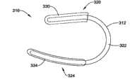
图10所示的心外膜夹310包括前部部分320、后部部分324以及前部部分320和后部部分324之间的侧面部分322。心外膜夹310还包括设置在部件312的前部部分320上的前护垫330、以及设置在部件312的后部部分324上的后护垫334。前护垫330可以帮助前部部分320保持在横窦中并且防止夹具310移动。后护垫334(在一些实施方案中为平坦的护垫)可以将力分布在心室壁的较大区域上而不会堵塞心肌中的血管。Theepicardial clip 310 shown in FIG. 10 includes ananterior portion 320 , aposterior portion 324 , and aside portion 322 between theanterior portion 320 and theposterior portion 324 . Theepicardial clip 310 also includes afront pad 330 disposed on thefront portion 320 of themember 312 , and arear pad 334 disposed on therear portion 324 of themember 312 .Anterior pad 330 may help maintainanterior portion 320 in the transverse sinus and preventclamp 310 from moving. Back pad 334 (a flat pad in some embodiments) can distribute force over a larger area of the ventricular wall without occluding blood vessels in the myocardium.

图11所示的心外膜夹410包括接近部件412的第一末端414的前部部分420、接近部件412的第二末端416的后部部分424、以及前部部分420和后部部分424之间的侧面部分422。心外膜夹410还包括以一定的间隔沿部件412的后部部分424设置的三个后护垫444。后护垫444可以包括用于接收缝合线、结扎物或组织锚定的孔,使得后护垫444可以与心脏的心室壁缝合或锚定。The epicardial clip 410 shown in FIG. 11 includes an anterior portion 420 proximal to the first end 414 of the member 412, a posterior portion 424 proximal to the second end 416 of the member 412, and a gap between the anterior portion 420 and the posterior portion 424. The side portion 422 between. The epicardial clip 410 also includes three rear pads 444 disposed at intervals along the rear portion 424 of the member 412 . The back pad 444 may include holes for receiving sutures, ligatures, or tissue anchors so that the back pad 444 may be sutured or anchored to the ventricular wall of the heart.

心外膜夹410在部件412的第一末端414处在前部部分420中还包括球状末端432。形成球状末端432可以保护大血管(如主动脉、肺动脉干、上腔大静脉)的血液动力学并且有助于前部部分420保持在横窦中。The epicardial clip 410 also includes a bulbous end 432 in the anterior portion 420 at the first end 414 of the member 412 . Forming the bulbous tip 432 can preserve the hemodynamics of the large vessels (eg, aorta, pulmonary trunk, superior vena cava) and help maintain the anterior portion 420 in the transverse sinus.

另外,心外膜夹410包括位于前部部分420和侧面部分422之间的较紧的弯曲442。弯曲442的弯曲半径可以小于侧面部分422的弯曲半径。弯曲442增加了该区域中的心室壁上的向里的力,从而在二尖瓣的A1-P1区域中提供额外的推力。Additionally, epicardial clip 410 includes a tighter bend 442 between front portion 420 and side portion 422 . The bend radius of bend 442 may be smaller than the bend radius of side portion 422 . The bend 442 increases the inward force on the ventricular wall in this region, providing additional thrust in the A1-P1 region of the mitral valve.

图12所示的心外膜夹510包括前部部分520、后部部分524、以及前部部分520和后部部分524之间的侧面部分522。心外膜夹510还包括多个位于部件512上的球540。可以选择性地对球540充气以在心脏的心外膜表面的所需位置处提供所需量的力。在一些实施方案中,每个球540可以各自地或者共同地充气至所需的大小。在一些实施方案中,可以独立地、同时地、以及/或者连续地对球540充气。可以通过一根或多根管子532(其可以与球540固定连接、或者在对球540合适地充气后将一根或多根管子532从球540上卸下来)来对球540充气。The epicardial clip 510 shown in FIG. 12 includes an anterior portion 520 , a posterior portion 524 , and a side portion 522 between the anterior portion 520 and the posterior portion 524 . Epicardial clip 510 also includes a plurality of balls 540 located on member 512 . The ball 540 can be selectively inflated to provide a desired amount of force at a desired location on the epicardial surface of the heart. In some embodiments, each ball 540 may be inflated to a desired size individually or collectively. In some embodiments, the balls 540 may be inflated independently, simultaneously, and/or continuously. The ball 540 may be inflated through one or more tubes 532 (which may be fixedly attached to the ball 540, or the one or more tubes 532 may be detached from the ball 540 after the ball 540 is properly inflated).

球540可以在所需的位置提供向里的力以使得瓣膜小叶更好地接合。例如,后部部分524可以包括三个球540。球540a可以在二尖瓣的A3-P3区域中提供所需的向里的推力,球540b可以在二尖瓣的A2-P2区域中提供所需的向里的推力,并且球540c可以在二尖瓣的A1-P1区域中提供所需的向里的推力。前部部分520上的球540d也可以在A1-P1区域中提供所需的推力并且/或者球540d可以有助于前部部分520保持在横窦中。The ball 540 can provide inward force at the desired location for better coaptation of the valve leaflets. For example, rear portion 524 may include three balls 540 . Ball 540a can provide the desired inward thrust in the A3-P3 region of the mitral valve, ball 540b can provide the desired inward thrust in the A2-P2 region of the mitral valve, and ball 540c can provide the desired inward thrust in the A2-P2 region of the mitral valve, and ball 540c can The required inward thrust is provided in the A1-P1 region of the cusp. The ball 540d on the anterior portion 520 can also provide the required thrust in the Al-P1 region and/or the ball 540d can help maintain the anterior portion 520 in the transverse sinus.

图13所示的心外膜夹610包括前部部分620、后部部分624、以及前部部分620和后部部分624之间的侧面部分622。心外膜夹610还包括从部件612延伸的臂612。当心外膜夹610被合适地设置在心脏周围时,臂646可以向里推向心室壁(左心室乳头肌的外部)以降低乳头肌间的距离,从而提高二尖瓣小叶的接合。在其它实施方案中,心外膜夹610可以具有一个或多个向里推向乳头肌的其它臂。例如,可以使用具有两个臂646的实施方案来将左心室中的乳头肌相互挤或推。Theepicardial clip 610 shown in FIG. 13 includes ananterior portion 620 , aposterior portion 624 , and aside portion 622 between theanterior portion 620 and theposterior portion 624 .Epicardial clip 610 also includes anarm 612 extending frommember 612 . When theepicardial clip 610 is properly positioned around the heart, thearms 646 can be pushed inwardly towards the ventricular wall (outside of the left ventricular papillary muscles) to reduce the distance between the papillary muscles, thereby improving coaptation of the mitral valve leaflets. In other embodiments,epicardial clip 610 may have one or more other arms that push inward toward the papillary muscle. For example, an embodiment with twoarms 646 can be used to squeeze or push the papillary muscles in the left ventricle against each other.

也可以使用与部件612连接的护垫644来将夹具610锚定或固定在心脏的心外膜表面上。例如,可以用紧钉等将夹具610缝合或锚定在心肌上以将夹具以合适的取向保持在心脏的周围。Cushion 644 attached tocomponent 612 may also be used to anchor orsecure clip 610 to the epicardial surface of the heart. For example,clip 610 may be sutured or anchored to the myocardium with staples or the like to maintain the clip in a proper orientation around the heart.

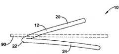
图14示出了心外膜夹710的其它实施方案。心外膜夹710由具有前部部分720、后部部分724以及夹在前部部分720和后部部分724之间的侧面部分722的部件712形成。侧面部分722相对于前部部分720和后部部分724这两者弯曲。因此,侧面部分722可以位于不同于前部部分720平面和后部部分724平面的平面内。侧面部分722的形状可以使得侧面部分722稳定在心脏心室壁的侧面部分。FIG. 14 shows another embodiment of an epicardial clip 710 . The epicardial clip 710 is formed from a member 712 having an anterior portion 720 , a posterior portion 724 , and a side portion 722 sandwiched between the anterior portion 720 and the posterior portion 724 . The side portions 722 are curved relative to both the front portion 720 and the rear portion 724 . Accordingly, the side portions 722 may lie in a different plane than the plane of the front portion 720 and the plane of the rear portion 724 . The shape of the side portion 722 can be such that the side portion 722 stabilizes the side portion of the heart ventricle wall.

图15示出另一心外膜夹810。心外膜夹810由具有前部部分820、后部部分824以及夹在前部部分820和后部部分824之间的侧面部分822的部件812形成。如图15所示,侧面部分822包括弹簧状螺旋环826,使得夹具810具有弹性,这使得在被所施加的力扭后再释放时部件812可以恢复其原始形状。这样,在夹具810插在心脏中时部件812的末端814和816可以彼此面对,但是当所施加的力从部件812除去时,螺旋环826的弹性往往将末端814和816彼此拉向一起。FIG. 15 shows anotherepicardial clip 810 . Theepicardial clip 810 is formed from amember 812 having ananterior portion 820 , aposterior portion 824 , and aside portion 822 sandwiched between theanterior portion 820 and theposterior portion 824 . As shown in FIG. 15, theside portion 822 includes a spring-likehelical ring 826 that renders theclamp 810 resilient, which allows themember 812 to return to its original shape when released after being twisted by an applied force. As such, ends 814 and 816 ofmember 812 may face each other whenclip 810 is inserted in the heart, but when the applied force is removed frommember 812, the elasticity ofhelical ring 826 tends to pull ends 814 and 816 toward each other.

图16为心外膜夹910的另一构造的俯视图。如图16所示,这样设置心外膜夹910:其面向从高处俯视安装有心外膜夹910的心脏的观察者。心外膜夹910由具有前部部分920、后部部分924以及夹在前部部分920和后部部分924之间的侧面部分922的部件912形成。前部部分920被构造成位于心脏的前部,后部部分924被构造成位于心脏的后部,并且侧面部分922被构造成位于心脏的侧面。例如,当被合适地设置在心脏的心外膜表面上时,前部部分920可以位于横窦中,后部部分924可以位于心脏后侧(如,房室沟处或房室沟下面或者心包斜窦中),并且侧面部分922可以在心脏侧面周围延伸以合适地放置前部部分920和后部部分924。FIG. 16 is a top view of another configuration of anepicardial clip 910 . As shown in FIG. 16 , theepicardial clip 910 is arranged such that it faces an observer looking down on the heart on which theepicardial clip 910 is installed from a height. Theepicardial clip 910 is formed from amember 912 having ananterior portion 920 , aposterior portion 924 , and aside portion 922 sandwiched between theanterior portion 920 and theposterior portion 924 .Anterior portion 920 is configured to be located at the front of the heart,posterior portion 924 is configured to be located at the rear of the heart, andlateral portion 922 is configured to be located at the side of the heart. For example, when properly positioned on the epicardial surface of the heart, theanterior portion 920 may be located in the transverse sinus and theposterior portion 924 may be located in the posterior side of the heart (e.g., at or below the atrioventricular groove or the pericardial oblique sinus), andlateral portion 922 may extend around the sides of the heart for proper placement ofanterior portion 920 andposterior portion 924.

心外膜夹910可以包括多个区域。如图16所示,心外膜夹910包括七个区域,可以想到区域的其它的数目和/或构造。在一些实施方案中,心外膜夹910的各区域可以是心外膜夹910的弯曲部分与笔直部分的交替区域。如图16所示,心外膜夹910包括第一区域981和第二区域982,它们跨越心外膜夹910的后部部分924。第一区域981可以为弯曲半径为R1并且长度为L1(该长度具有角度θ1)的弯曲区域。在一些实施方案中,第一区域981的弯曲半径R1可以为约1英寸至约2英寸,约1.25英寸至约1.75英寸,或者约1.5英寸,这取决于心脏的特定解剖形状。第一区域981可以延伸穿过角度θ1。在一些实施方案中,角度θ1可以为约20°至约40°,或者约30°。在一些实施方案中,第一区域981的长度L1可以为约0.5英寸至约1.5英寸,约0.75英寸至约1.0英寸,或者约0.785英寸。第一区域981的弯曲性可以使得其与心脏后侧的弯曲度一致。Epicardial clip 910 may include multiple regions. As shown in Figure 16,epicardial clip 910 includes seven regions, although other numbers and/or configurations of regions are contemplated. In some embodiments, the regions of theepicardial clip 910 may be alternating regions of curved and straight portions of theepicardial clip 910 . As shown in FIG. 16 , theepicardial clip 910 includes afirst region 981 and asecond region 982 that span theposterior portion 924 of theepicardial clip 910 . Thefirst region 981 may be a curved region with a radius of curvature R1 and a length L1 (the length has an angle θ1 ). In some embodiments, the radius of curvature R1 of thefirst region 981 can be about 1 inch to about 2 inches, about 1.25 inches to about 1.75 inches, or about 1.5 inches, depending on the particular anatomical shape of the heart. Thefirst region 981 may extend through the angle θ1 . In some embodiments, angle θ1 may be from about 20° to about 40°, or about 30°. In some embodiments, the length L1 of thefirst region 981 can be about 0.5 inches to about 1.5 inches, about 0.75 inches to about 1.0 inches, or about 0.785 inches. The curvature of thefirst region 981 may be such that it conforms to the curvature of the posterior side of the heart.

第二区域982可以为笔直或基本笔直的区域,其长度L2为约0.4英寸至约0.8英寸,约0.5英寸至约0.7英寸,或者约0.5英寸。Thesecond region 982 can be a straight or substantially straight region having a lengthL2 of about 0.4 inches to about 0.8 inches, about 0.5 inches to about 0.7 inches, or about 0.5 inches.

心外膜夹910还可以包括第三区域983、第四区域984和第五区域985,它们跨越心外膜夹910的侧面部分922。第三区域983可以为弯曲半径为R3并且长度为L3(该长度具有角度θ3)的弯曲区域。在一些实施方案中,第三区域983的弯曲半径R3可以为约0.25英寸至约1.5英寸,约0.5英寸至约1.0英寸,或者约0.75英寸,这取决于心脏的特定解剖形状。第三区域983可以延伸穿过角度θ3。在一些实施方案中,角度θ3可以为约75°至约130°,约90°至约115°,或者约105°。在一些实施方案中,第三区域983的长度L3可以为约0.5英寸至约2.0英寸,约1.0英寸至约1.5英寸,或者约1.375英寸。第三区域983的弯曲性可以使得其与心脏前侧的弯曲度一致。Theepicardial clip 910 may also include athird region 983 , afourth region 984 , and afifth region 985 spanning theside portion 922 of theepicardial clip 910 . Thethird region 983 may be a curved region with a radius of curvature R3 and a length L3 (the length has an angle θ3 ). In some embodiments,third region 983 may have a radius of curvatureR3 of about 0.25 inches to about 1.5 inches, about 0.5 inches to about 1.0 inches, or about 0.75 inches, depending on the particular anatomical shape of the heart. Thethird region 983 may extend through the angle θ3 . In some embodiments, angleθ3 can be from about 75° to about 130°, from about 90° to about 115°, or about 105°. In some embodiments, the lengthL3 of thethird region 983 can be about 0.5 inches to about 2.0 inches, about 1.0 inches to about 1.5 inches, or about 1.375 inches. The curvature of thethird region 983 may be such that it conforms to the curvature of the front side of the heart.

第四区域984可以为笔直或基本笔直的区域,其长度L4为约0.2英寸至约0.5英寸,约0.3英寸至约0.4英寸,或者约0.375英寸。Fourth region 984 may be a straight or substantially straight region having a lengthL4 of about 0.2 inches to about 0.5 inches, about 0.3 inches to about 0.4 inches, or about 0.375 inches.

第五区域985可以为弯曲半径为R5并且长度为L5(该长度具有角度θ5)的弯曲区域。在一些实施方案中,第五区域985的弯曲半径R5可以为约0.25英寸至约0.75英寸,约0.4英寸至约0.5英寸,或者约0.4625英寸,这取决于心脏的特定解剖形状。第五区域985可以延伸穿过角度θ5。在一些实施方案中,角度θ5可以为约75°至约130°,约90°至约115°,或者约110°。在一些实施方案中,第五区域985的长度L5可以为约0.5英寸至约2.0英寸,约0.75英寸至约1.0英寸,或者约0.888英寸。第五区域985的弯曲性可以使得其与心脏前侧的弯曲度一致。Thefifth region 985 may be a curved region with a radius of curvature R5 and a length L5 having an angle θ5 . In some embodiments,fifth region 985 may have a radius of curvatureR5 of about 0.25 inches to about 0.75 inches, about 0.4 inches to about 0.5 inches, or about 0.4625 inches, depending on the particular anatomical shape of the heart.Fifth region 985 may extend through angle θ5 . In some embodiments, angleθ5 can be from about 75° to about 130°, from about 90° to about 115°, or about 110°. In some embodiments, the lengthL5 of thefifth region 985 can be about 0.5 inches to about 2.0 inches, about 0.75 inches to about 1.0 inches, or about 0.888 inches. The curvature of thefifth region 985 may be such that it conforms to the curvature of the anterior side of the heart.

另外,心外膜夹910可以包括第六区域986和第七区域987,它们跨越心外膜夹910的前部部分920。第六区域986可以为笔直或基本笔直的区域,其长度L6为约0.5英寸至约1.0英寸,约0.6英寸至约0.8英寸,或者约0.75英寸。Additionally, theepicardial clip 910 can include asixth region 986 and aseventh region 987 that span theanterior portion 920 of theepicardial clip 910 . Thesixth region 986 can be a straight or substantially straight region having a length L6 of about 0.5 inches to about 1.0 inches, about 0.6 inches to about 0.8 inches, or about 0.75 inches.

第七区域987可以为弯曲半径为R7并且长度为L7(该长度具有角度θ7)的弯曲区域。在一些实施方案中,第七区域987的弯曲半径R7可以为约0.25英寸至约0.75英寸,约0.3英寸至约0.6英寸,或者约0.5英寸,这取决于心脏的特定解剖形状。第七区域987可以延伸穿过角度θ7。在一些实施方案中,角度θ7可以为约75°至约120°,约80°至约100°,或者约90°。在一些实施方案中,第七区域987的长度L7可以为约0.5英寸至约1.25英寸,约0.6英寸至约0.8英寸,或者约0.785英寸。第七区域987的弯曲性可以使得当前部部分920位于心脏的横窦中时其位于主动脉根部周围从而进一步将心外膜夹910锚定在横窦中。Theseventh region 987 may be a curved region with a radius of curvature R7 and a length L7 (the length has an angle θ7 ). In some embodiments, the radius of curvatureR7 of theseventh region 987 can be about 0.25 inches to about 0.75 inches, about 0.3 inches to about 0.6 inches, or about 0.5 inches, depending on the particular anatomical shape of the heart.Seventh region 987 may extend through angle θ7 . In some embodiments, angleθ7 can be about 75° to about 120°, about 80° to about 100°, or about 90°. In some embodiments, the lengthL7 of theseventh region 987 can be about 0.5 inches to about 1.25 inches, about 0.6 inches to about 0.8 inches, or about 0.785 inches. The curvature of theseventh region 987 may allow theanterior portion 920 to be located around the aortic root when located in the transverse sinus of the heart thereby further anchoring theepicardial clip 910 in the transverse sinus.

图17为沿图16的17-17线截取的心外膜夹910的侧视图。如图17所示,心外膜夹910可以具有螺旋性。例如,侧面部分922可以包括一个或多个螺旋弯曲,使得前部部分920不位于与后部部分924相同的平面内。例如,心外膜夹910的第三区域983和/或第五区域985可以包括螺旋弯曲。FIG. 17 is a side view ofepicardial clip 910 taken along line 17-17 of FIG. 16 . As shown in FIG. 17, theepicardial clip 910 may have helicity. For example,side portion 922 may include one or more helical bends such thatfront portion 920 does not lie in the same plane asrear portion 924 . For example,third region 983 and/orfifth region 985 ofepicardial clip 910 may include a helical bend.

另外,如图17所示,第七区域987可以与相邻的第六区域986形成钝角θ8。例如,第七区域987与第六区域986的钝角θ8可以为约120°至约170°,约130°至约160°,或者约155°。角度θ8可以使得第七区域987保持在心脏的横窦内。In addition, as shown in FIG. 17 , theseventh region 987 may form an obtuse angle θ8 with the adjacentsixth region 986 . For example, the obtuse angle θ8 between theseventh region 987 and thesixth region 986 may be about 120° to about 170°, about 130° to about 160°, or about 155°. The angleθ8 can maintain theseventh region 987 within the transverse sinus of the heart.

图18为沿图16的18-18线截取的心外膜夹910的侧视图。如图18所示,前部部分920不位于与后部部分924相同的平面内。例如,前部部分920可以位于这样的想像平面内,其中该想像平面与后部部分924所位于的想像平面成角度θ9。例如,前部部分920与后部部分924的角度θ9可以为约10°至约30°,约20°至约25°,或者约23.5°。角度θ9可以使得前部部分920位于心脏的横窦内,同时使得后部部分924位于心脏后侧(如心脏的房室沟处或房室沟下面或者斜窦中),并且侧面部分922在心脏侧面延伸。FIG. 18 is a side view ofepicardial clip 910 taken along line 18-18 of FIG. 16 . As shown in FIG. 18 , thefront portion 920 does not lie in the same plane as therear portion 924 . For example, thefront portion 920 may lie in an imaginary plane that is at an angle θ9 to the imaginary plane in which therear portion 924 lies. For example, the angle θ9 of thefront portion 920 to therear portion 924 can be about 10° to about 30°, about 20° to about 25°, or about 23.5°. The angleθ9 may be such that theanterior portion 920 is located within the transverse sinus of the heart, while theposterior portion 924 is located posterior to the heart (e.g., at or below the atrioventricular groove of the heart or in the oblique sinus), and thelateral portion 922 is in the The heart extends laterally.

图19和20为另一心外膜夹1010的透视图。心外膜夹1010可以包括前部部分1020、后部部分1024以及夹在前部部分1020和后部部分1024之间的侧面部分1022。前部部分1020被构造成位于心脏的前部,后部部分1024被构造成位于心脏的后部,并且侧面部分1022被构造成位于心脏的侧面。例如,当被合适地设置在心脏的心外膜表面上时,前部部分1020可以位于横窦中,后部部分1024可以位于心脏后侧(如,房室沟处或房室沟下面或者心包斜窦中),并且侧面部分1022可以在心脏侧面周围延伸以合适地放置前部部分1020和后部部分1024。19 and 20 are perspective views of anotherepicardial clip 1010 . Theepicardial clip 1010 can include ananterior portion 1020 , aposterior portion 1024 , and aside portion 1022 sandwiched between theanterior portion 1020 and theposterior portion 1024 .Anterior portion 1020 is configured to be located at the front of the heart,posterior portion 1024 is configured to be located at the rear of the heart, andlateral portion 1022 is configured to be located at the side of the heart. For example, when properly positioned on the epicardial surface of the heart, theanterior portion 1020 may be located in the transverse sinus and theposterior portion 1024 may be located in the posterior side of the heart (e.g., at or below the atrioventricular groove or the pericardial groove). oblique sinus), andlateral portion 1022 may extend around the sides of the heart for proper placement ofanterior portion 1020 andposterior portion 1024.

在一些实施方案中,心外膜夹1010可以包括芯元件(图中未示出),如被外部元件1030包围或者裹在外部元件1030中的具有合适弯曲度的线材或棒。在一些实施方案中,外部元件1030可以为防止创伤的、可生物吸收的并且/或者生物适应性的覆层。例如,在一些实施方案中,外部元件1030可以为顺应材料,例如遍布有聚合物的成型品,如遍布有硅酮的成型品,其成型、形成或设置在内部芯元件的周围。在一些实施方案中,外部元件1030可以为与心脏轮廓互补的不规则形状的元件。外部元件1030可以更均匀地将应力从心外膜夹1010分布至心脏表面,防止设置在心脏上的夹具1010的侧面移动,并且/或者提供用于将夹具1010固定到心脏上的区域。例如,在一些实施方案中,外部元件1030(如遍布有硅酮的成型品)可以分布夹紧力以避免心肌层上的动脉和/或静脉堵塞。在一些实施方案中,外部元件1030可以提供充分的扭转挠性,从而使得夹具1010与心脏的轮廓相适应。In some embodiments, theepicardial clip 1010 may include a core member (not shown), such as a wire or rod having a suitable curvature, surrounded by or encased in theouter member 1030 . In some embodiments, theouter element 1030 can be an atraumatic, bioabsorbable and/or biocompatible coating. For example, in some embodiments, theouter element 1030 may be a compliant material, such as a polymer-over-mold, such as a silicone-over-mold, that is molded, formed, or disposed about the inner core element. In some embodiments, theouter element 1030 can be an irregularly shaped element that complements the contours of the heart.Outer element 1030 may more evenly distribute stress fromepicardial clip 1010 to the surface of the heart, prevent sideways movement ofclip 1010 disposed on the heart, and/or provide an area for securingclip 1010 to the heart. For example, in some embodiments, the outer member 1030 (eg, a silicone-over-mold) can distribute clamping forces to avoid occlusion of arteries and/or veins on the myocardium. In some embodiments,outer member 1030 can provide sufficient torsional flexibility such thatclip 1010 conforms to the contours of the heart.

另外,尽管未示出,在一些实施方案中,外部元件1030可以包裹在织物覆层或护套中。在一些实施方案中,织物覆层可以自身被缝合、粘附、夹别或固定、或者被缝合、粘附、夹别或固定在外部元件1030上以保持该织物覆层。例如,在一些实施方案中,根据需要,所述织物覆层可以为PTFE材料、聚酯编织织物、聚酯丝绒、聚丙烯毡、编织或编织的织物、非编织织物、多孔材料、或者其它织物。在一些实施方案中,织物覆层可以促进心脏心外膜表面上的组织生长,可以将组织生长提供为织物护套的空隙,以及/或者提供充足的摩擦力(拉力)以保持夹具1010与心脏接触并防止已设置在心脏上的设备移动。其中和/或其上的组织生长可以使得心外膜夹1010长期保持在心脏中的所需位置处并防止腐蚀。Additionally, although not shown, in some embodiments, theouter member 1030 may be wrapped in a fabric covering or sheath. In some embodiments, the fabric covering may be stitched, adhered, clipped or secured to itself, or to theouter element 1030 to retain the fabric covering. For example, in some embodiments, the fabric covering may be PTFE material, polyester woven fabric, polyester velor, polypropylene felt, woven or woven fabric, non-woven fabric, porous material, or other fabrics as desired. . In some embodiments, the fabric covering can promote tissue growth on the epicardial surface of the heart, can provide tissue growth as a void for the fabric sheath, and/or provide sufficient friction (pull) to holdclamp 1010 to the heart Contact and prevent movement of devices that have been placed on the heart. Tissue growth in and/or thereon may enable long-term retention of theepicardial clip 1010 in a desired location in the heart and prevent corrosion.

在一些实施方案中,心外膜夹1010可以还包括药物洗脱涂层、或者作为外部元件和/或织物覆层的替代物而具有药物洗脱涂层。药物洗脱涂层可以为治疗药剂在特定的期间内的控制释放。治疗药剂可以为可提供所需效果的任意医用药剂。合适的治疗药剂包括药物、遗传物质、以及生物学材料。一些可被负载在药物洗脱涂层中的合适的治疗药剂包括但不限于抗生素、抗菌剂、抗氧化剂、抗心律失常药、细胞生长因子、免疫抑制剂(如他克莫司、依维莫司以及雷帕霉素(西罗莫司))、治疗性抗体、伤口愈合剂、治疗性转基因构建体、肽类、蛋白质、细胞外基质成分、甾体和非甾体消炎药、抗增生药(如甾体类)、维生素和再狭窄抑制药,如Taxol

Figure BPA00001325007100201
、紫杉醇(即,紫杉醇、紫杉醇类似物、或者紫杉醇衍生物、以及它们的混合物)。In some embodiments, theepicardial clip 1010 may also include or have a drug eluting coating as an alternative to an outer member and/or fabric covering. Drug eluting coatings can provide controlled release of therapeutic agents over a specified period of time. A therapeutic agent can be any medical agent that provides a desired effect. Suitable therapeutic agents include drugs, genetic material, and biological material. Some suitable therapeutic agents that can be loaded into drug eluting coatings include, but are not limited to, antibiotics, antibacterials, antioxidants, antiarrhythmics, cellular growth factors, immunosuppressants (e.g., tacrolimus, everolimus, and rapamycin (sirolimus), therapeutic antibodies, wound healing agents, therapeutic transgenic constructs, peptides, proteins, extracellular matrix components, steroidal and nonsteroidal anti-inflammatory drugs, antiproliferative drugs (such as steroids), vitamins, and restenosis inhibitors such as Taxol
Figure BPA00001325007100201
, paclitaxel (ie, paclitaxel, paclitaxel analogs, or paclitaxel derivatives, and mixtures thereof).

如图21所示,当从上方观察时,心外膜夹1010通常可以具有U型或C型。心外膜夹1010可以为单片式的单一元件,或者心外膜夹1010可以由连接在一起的两个以上的单独的元件形成。例如,如图21所示,可以一体化形成后部部分1024和侧面部分1022,并且前部部分1020可以连接在侧面部分1022上。例如,前部部分1020可以包括用于将前部部分1020连接至侧面部分1022上的连接部分或连接器1025。在一些实施方案中,连接部分1025可以为在一部分前部部分1020上延伸并且在一部分侧面部分1022上延伸的管状元件。As shown in Figure 21, theepicardial clip 1010 may generally have a U-shape or a C-shape when viewed from above. Theepicardial clip 1010 may be a single piece that is a single component, or theepicardial clip 1010 may be formed from two or more separate components joined together. For example, as shown in FIG. 21 ,rear portion 1024 andside portion 1022 may be integrally formed, andfront portion 1020 may be attached toside portion 1022 . For example, thefront portion 1020 may include connecting portions orconnectors 1025 for connecting thefront portion 1020 to theside portions 1022 . In some embodiments, connectingportion 1025 may be a tubular element extending over a portion offront portion 1020 and over a portion ofside portion 1022 .

如图21所示,前部部分1020可以包括双元件(double-member,如,自身向后弯曲形成U型的元件)。发现在使用过程中前部部分1020的双元件可以提高在横窦中的保持性和/或稳定性。前部部分1020的双元件可以包括通过连接部1043(其可以为弯曲部)而连接的第一臂1041和第二臂1042。在一些实施方案中,第一臂1041可以与第二臂1042平行,并且连接部1043可以基本上与第一臂1041和第二臂1042垂直。注意的是,在一些实施方案中,第二臂1042的一部分可以延伸进入连接部分1025中或者与侧面部分1022相连接。在一些实施方案中,前部部分1020的弯曲部分的弯曲度可以与侧面部分1022的弯曲度垂直。在一些实施方案中,前部部分1020的弯曲部分的弯曲度可以与二尖瓣平面垂直。在一些实施方案中,前部部分1020可以基本上从横窦的下部至横窦的上部占据横窦。在一些实施方案中,第二臂1042可以位于横窦门,同时第一臂1041可以相对于心包(其在心房上部将横窦和斜窦分开)折返而自身锚定。As shown in FIG. 21, thefront portion 1020 may comprise a double-member (eg, a member that bends back on itself to form a U-shape). The dual elements of theanterior portion 1020 were found to improve retention and/or stability in the transverse sinus during use. The dual member of thefront portion 1020 may include afirst arm 1041 and asecond arm 1042 connected by a connection 1043 (which may be a bend). In some embodiments, thefirst arm 1041 can be parallel to thesecond arm 1042 , and the connectingportion 1043 can be substantially perpendicular to thefirst arm 1041 and thesecond arm 1042 . Note that in some embodiments, a portion of thesecond arm 1042 may extend into theconnection portion 1025 or be connected to theside portion 1022 . In some embodiments, the curvature of the curved portion of thefront portion 1020 may be perpendicular to the curvature of theside portions 1022 . In some embodiments, the curvature of the curved portion of theanterior portion 1020 may be perpendicular to the plane of the mitral valve. In some embodiments, theanterior portion 1020 can occupy the transverse sinus substantially from the lower portion of the transverse sinus to the upper portion of the transverse sinus. In some embodiments, thesecond arm 1042 can be located at the portal of the transverse sinus, while thefirst arm 1041 can anchor itself relative to the reentry of the pericardium (which separates the transverse and oblique sinuses in the upper part of the atrium).

图21A示出心外膜夹1010的各部分的一些合适的尺寸。尽管指出了心外膜夹1010的一些合适的尺寸,但是本领域技术人员根据本公开会理解到,如果需要的话,本文所公开的其它实施方案、以及其它可想到的实施方案也可以包括相似的尺寸。例如,在一些实施方案中,心外膜夹10、110、210、310、410、510、610、710和810的相应区域可以具有与此相似的尺寸。FIG. 21A shows some suitable dimensions for the various parts of theepicardial clip 1010 . While some suitable dimensions for theepicardial clip 1010 are indicated, those skilled in the art will appreciate in light of this disclosure that other embodiments disclosed herein, as well as other conceivable embodiments, may also include similar size. For example, in some embodiments, corresponding regions ofepicardial clips 10, 110, 210, 310, 410, 510, 610, 710, and 810 may have similar dimensions thereto.

如图21A所示,例如,前部部分1020(其可以为心外膜夹1010的笔直部分)的长度L1可以为约1英寸至约3英寸,约1英寸至约2.5英寸,约1.25英寸至约2英寸,或者约1.28英寸至约2.07英寸。在其它实施方案中,例如,前部部分1020可以为弯曲部分,其弧长为约1英寸至约3英寸,约1英寸至约2.5英寸,约1.25英寸至约2英寸,或者约1.28英寸至约2.07英寸。As shown in Figure 21A, for example, the lengthL of the anterior portion 1020 (which may be the straight portion of the epicardial clip 1010) may be about 1 inch to about 3 inches, about 1 inch to about 2.5 inches, about 1.25 inches to about 2 inches, or about 1.28 inches to about 2.07 inches. In other embodiments, for example,front portion 1020 can be a curved portion with an arc length of about 1 inch to about 3 inches, about 1 inch to about 2.5 inches, about 1.25 inches to about 2 inches, or about 1.28 inches to about 2 inches. About 2.07 inches.

心外膜夹1010可以具有前/侧弯曲部分1021,其限定了前部部分1020与侧面部分1022之间的过度区域。在一些实施方案中,前/侧弯曲部分1021可以被认为是前部部分1020的一部分,而在其它的实施方案中,前/侧弯曲部分1021可以被认为是侧面部分1022的一部分。在其它的实施方案中,前/侧弯曲部分1021的第一部分可以与前部部分1020连接,而前/侧弯曲部分1021的第二部分可以与侧面部分1022连接。前/侧弯曲部分1021的弧长L2可以为约0.25英寸至约1.5英寸,约0.5英寸至约1英寸,约0.4英寸至约1.1英寸,或者约0.43英寸至约1.09英寸。前/侧弯曲部分1021的弯曲度半径R1可以为约0.1英寸至约1.25英寸,约0.2英寸至约1英寸,约0.24英寸至约0.75英寸,或者约0.24英寸至约0.74英寸。Theepicardial clip 1010 may have an anterior/lateralcurved portion 1021 that defines a transition region between ananterior portion 1020 and alateral portion 1022 . In some embodiments, front/side curvedportion 1021 may be considered part offront portion 1020 , while in other embodiments, front/side curvedportion 1021 may be considered part ofside portion 1022 . In other embodiments, a first portion of front/side curvedportion 1021 may be connected tofront portion 1020 and a second portion of front/side curvedportion 1021 may be connected toside portion 1022 . The arc lengthL2 of the front/side curvedportion 1021 may be from about 0.25 inches to about 1.5 inches, from about 0.5 inches to about 1 inch, from about 0.4 inches to about 1.1 inches, or from about 0.43 inches to about 1.09 inches. Front/side curvedportion 1021 may have a radius of curvature R1 of about 0.1 inches to about 1.25 inches, about 0.2 inches to about 1 inch, about 0.24 inches to about 0.75 inches, or about 0.24 inches to about 0.74 inches.

侧面部分1022可以包括位于前/侧弯曲部分1021与后/侧弯曲部分1023之间的笔直部分。因此,在一些实施方案中,侧面部分1022可以包括位于侧面部分1022的第一弯曲部分与第二弯曲部分之间的笔直部分。侧面部分1022的笔直部分的长度L3可以为约0.1英寸至约0.5英寸,约0.2英寸至约0.4英寸,约0.15英寸至约0.35英寸,或者约0.15英寸至约0.35英寸。Theside portion 1022 may include a straight portion between the front/side curvedportion 1021 and the rear/side curvedportion 1023 . Thus, in some embodiments,side portion 1022 may include a straight portion between the first curved portion and the second curved portion ofside portion 1022 . The lengthL3 of the straight portion ofside portion 1022 may be from about 0.1 inches to about 0.5 inches, from about 0.2 inches to about 0.4 inches, from about 0.15 inches to about 0.35 inches, or from about 0.15 inches to about 0.35 inches.

心外膜夹1010可以具有后/侧弯曲部分1023,其限定了侧面部分1022与后部部分1024之间的过度区域。在一些实施方案中,后/侧弯曲部分1023可以被认为是侧面部分1022的一部分,而在其它的实施方案中,后/侧弯曲部分1023可以被认为是后部部分1024的一部分。在其它的实施方案中,后/侧弯曲部分1023的第一部分可以与侧面部分1022连接,而后/侧弯曲部分1023的第二部分可以与后部部分1024连接。后/侧弯曲部分1023的弧长L4可以为约0.25英寸至约1.5英寸,约0.5英寸至约1.0英寸,约0.65英寸至约1.1英寸,或者约0.64英寸至约1.1英寸。后/侧弯曲部分1023的弯曲度半径R2可以为约0.2英寸至约1.25英寸,约0.3英寸至约1.0英寸,约0.4英寸至约0.85英寸,或者约0.44英寸至约0.87英寸。Theepicardial clip 1010 may have a posterior/lateralcurved portion 1023 that defines a transition region between thelateral portion 1022 and theposterior portion 1024 . In some embodiments, rear/side curvedportion 1023 may be considered part ofside portion 1022 , while in other embodiments, rear/side curvedportion 1023 may be considered part ofrear portion 1024 . In other embodiments, a first portion of rear/side curvedportion 1023 may be connected toside portion 1022 and a second portion of rear/side curvedportion 1023 may be connected torear portion 1024 . The arc lengthL4 of the rear/side curvedportion 1023 may be from about 0.25 inches to about 1.5 inches, from about 0.5 inches to about 1.0 inches, from about 0.65 inches to about 1.1 inches, or from about 0.64 inches to about 1.1 inches. The radius of curvatureR2 of the rear/side curvedportion 1023 may be from about 0.2 inches to about 1.25 inches, from about 0.3 inches to about 1.0 inches, from about 0.4 inches to about 0.85 inches, or from about 0.44 inches to about 0.87 inches.

例如,后部部分1024(其可以为心外膜夹1010的弯曲部分)的弧长L5可以为约1英寸至约3英寸,约1.25英寸至约2.75英寸,约1.5英寸至约2.5英寸,或者约1.55英寸至约2.5英寸。后部部分1024的弯曲度半径R3可以为约2英寸至约5英寸,约2.5英寸至约4.5英寸,约3英寸至约4英寸,或者约2.9英寸至约4.1英寸。For example, the arc lengthL5 of the posterior portion 1024 (which may be the curved portion of the epicardial clip 1010) may be from about 1 inch to about 3 inches, from about 1.25 inches to about 2.75 inches, from about 1.5 inches to about 2.5 inches, Or about 1.55 inches to about 2.5 inches. The radius of curvatureR3 of therear portion 1024 may be from about 2 inches to about 5 inches, from about 2.5 inches to about 4.5 inches, from about 3 inches to about 4 inches, or from about 2.9 inches to about 4.1 inches.

在一些实施方案中,前部部分1020可以能够相对于后部部分1024和/或侧面部分1022而旋转。例如,前部部分1020可以能够围绕纵向穿过前部部分1020的连接元件1025的轴旋转。在其它的实施方案中,前部部分1020可以相对于后部部分1024和/或侧面部分1022以固定的角度被取向。In some embodiments, thefront portion 1020 may be capable of rotating relative to therear portion 1024 and/or theside portions 1022 . For example, thefront portion 1020 may be rotatable about an axis extending longitudinally through the connectingelement 1025 of thefront portion 1020 . In other embodiments,front portion 1020 may be oriented at a fixed angle relative torear portion 1024 and/orside portions 1022 .

图22为具有旋转后的前部部分1020的心外膜夹1010的透视图,其中所述前部部分1020旋转至这样的位置,使得前部部分1020所处的想像平面基本上与后部部分1024和/或侧面部分1022所处的想像平面垂直。22 is a perspective view of anepicardial clip 1010 with ananterior portion 1020 rotated to a position such that theanterior portion 1020 resides in an imaginary plane substantially parallel to the posterior portion. The imaginary plane in which 1024 and/orside portion 1022 lie is vertical.

图23A-23C为心外膜夹1010的侧视图,示出了在相对于后部部分1024和/或侧面部分1022的三个可能的旋转后的位置处的前部部分1020。在一些实施方案中,前部部分1020能够相对于后部部分1024和/或侧面部分1022旋转之任意的角度θ。图23A示出了相对于后部部分1024和侧面部分1022旋转至约90°的前部部分1020。图23B示出了相对于后部部分1024和侧面部分1022旋转至约60°的前部部分1020。图23C示出了相对于后部部分1024和侧面部分1022旋转至约120°的前部部分1020。可以理解的是,在一些实施方案中,前部部分1020可旋转约0°至约180°,约30°至约150°,约45°至约135°,约60°至约120°,约70°至约110°,约80°至约100°,或者其它任意所需旋转范围。23A-23C are side views ofepicardial clip 1010 showinganterior portion 1020 in three possible rotated positions relative toposterior portion 1024 and/orlateral portion 1022 . In some embodiments, thefront portion 1020 is capable of rotating relative to therear portion 1024 and/or theside portions 1022 by any angle θ. FIG. 23A showsfront portion 1020 rotated to about 90° relative torear portion 1024 andside portions 1022 . FIG. 23B showsfront portion 1020 rotated to about 60° relative torear portion 1024 andside portions 1022 . FIG. 23C showsfront portion 1020 rotated to about 120° relative torear portion 1024 andside portions 1022 . It is understood that, in some embodiments, thefront portion 1020 can be rotated from about 0° to about 180°, from about 30° to about 150°, from about 45° to about 135°, from about 60° to about 120°, about 70° to about 110°, about 80° to about 100°, or any other desired range of rotation.

图24为向下观看其上设置有心外膜夹1010的心脏的心房时的俯视图。如图24所示,当被设置在心脏上时,心外膜夹1010的前部部分1020可以被设置在横窦TS(肺动脉干PT和主动脉A之后并且上腔大静脉SVC之前)中。当被设置在横窦TS中时,前部部分1020的双元件可以基本上垂直地放置在横窦TS中。例如,前部部分1020的双元件、或者前部部分1020的其它部件可以基本上从横窦的下部至横窦的上部占据或跨越横窦。发现前部部分的位置和形状可以提高在横窦TS中的保持性和/或稳定性。FIG. 24 is a top view looking down at the atrium of the heart with theepicardial clip 1010 placed thereon. As shown in Figure 24, when placed on the heart, theanterior portion 1020 of theepicardial clip 1010 may be placed in the transverse sinus TS (after the pulmonary trunk PT and aorta A and anterior to the superior vena cava SVC). When positioned in the transverse sinus TS, the dual elements of theanterior portion 1020 may be placed substantially vertically in the transverse sinus TS. For example, dual elements ofanterior portion 1020, or other components ofanterior portion 1020, may occupy or span the transverse sinus substantially from the lower portion of the transverse sinus to the upper portion of the transverse sinus. It was found that the position and shape of the anterior portion can improve retention and/or stability in the transverse sinus TS.

如图24所示,后部部分1024可以设置在心脏后侧的心外膜表面上,如房室沟处或房室沟下面或者斜窦OS中。因此,保持在前部部分1020与后部部分1024之间的距离可以将心脏的前壁推向心脏的后壁,对心脏的几何形状整形。例如,将心外膜夹1010合适地设置在一部分心脏的周围,可以改变二尖瓣环的前后尺寸和/或隔外侧尺寸以对二尖瓣环整形从而减小二尖瓣反流。As shown in FIG. 24, theposterior portion 1024 may be disposed on the epicardial surface on the posterior side of the heart, such as at or below the atrioventricular groove or in the oblique sinus OS. Thus, maintaining a distance between theanterior portion 1020 and theposterior portion 1024 may push the anterior wall of the heart towards the posterior wall of the heart, shaping the geometry of the heart. For example, appropriate placement ofepicardial clip 1010 around a portion of the heart can alter the anteroposterior and/or lateral septal dimensions of the mitral annulus to reshape the mitral annulus to reduce mitral regurgitation.

图25-29示出图19和20所示心外膜夹1010的可选择的构造。如图25所示,心外膜夹1010可以包括锚定的或不旋转的前部部分1020。在该实施方案中,可以形成或选择前部部分1020以具有与特定患者的解剖轮廓互补的所需角度和/或弯曲度,从而确保控制前部部分1020与心脏结构间的力。例如,图25所示的前部部分1020包括上臂部1026、下臂部1027、以及在上臂部1026和下臂部1027之间延伸的侧部1028。下臂部1027可以被构造成位于横窦的下部。上臂部1026可以被构造成位于横窦的上部。25-29 illustrate alternative configurations for theepicardial clip 1010 shown in FIGS. 19 and 20 . As shown in FIG. 25 ,epicardial clip 1010 may include ananterior portion 1020 that is anchored or non-rotating. In this embodiment,anterior portion 1020 can be formed or selected to have a desired angle and/or curvature that complements a particular patient's anatomical contours to ensure controlled force betweenanterior portion 1020 and cardiac structures. For example,front portion 1020 shown in FIG. 25 includesupper arm 1026 ,lower arm 1027 , andside 1028 extending betweenupper arm 1026 andlower arm 1027 . Thelower arm 1027 may be configured to be located in the lower portion of the transverse sinus. Theupper arm 1026 may be configured to be located in the upper portion of the transverse sinus.

在一些实施方案中,下臂部1027可以包括具有向下弯曲的凹向弯曲度的弧,使得前部部分1020的下臂部1027更好地与横窦的前环或底部的自然鞍形相一致,并使得下臂部1027的端部1029可以设置在右心房与左心房之间的隔膜壁的底面、或者与右心房与左心房之间的隔膜壁的底面接触。In some embodiments, thelower arm 1027 may comprise an arc with a downwardly curved concave curvature such that thelower arm 1027 of theanterior portion 1020 better conforms to the natural saddle shape of the anterior ring or floor of the transverse sinus , and make theend 1029 of thelower arm 1027 be placed on the bottom surface of the septum wall between the right atrium and the left atrium, or contact with the bottom surface of the septum wall between the right atrium and the left atrium.

如图26的可选择的构造所示,前部部分1020可以为包括上臂部1026和下臂部1027(当放在横窦中时,其被构造成位于上臂部1026下面)的封闭环。下臂部1027可以位于横窦的底部,同时上臂部1026可以相对于心包(其在心房上部将横窦和斜窦分开)折返而自身锚定。另外,所示出的侧面部分1022通过位于上臂部1026和下臂部1027间的连接点与前部部分1020的封闭环的中间部分相连。在图26所示的实施方案中,前部部分1020相对于心外膜夹1010的侧面部分1022和/或后部部分1024而自由旋转。已经发现,例如,将侧面部分1022连接在前部部分1020的中间部位同时使前部部分1020相对于心外膜夹1010的其它部分自由旋转,可以有助于将力均匀地分散在前部部分1020的上臂部1026与下臂部1027间的心脏的结构上。更均匀地分散力,通过具有两个小的凸起而不是一个大的凸起,可以降低心脏结构的肿胀。As shown in an alternative configuration of FIG. 26, theanterior portion 1020 may be a closed loop including anupper arm 1026 and a lower arm 1027 (configured to lie below theupper arm 1026 when placed in the transverse sinus). Thelower arm 1027 may be located at the floor of the transverse sinus, while theupper arm 1026 may anchor itself relative to the pericardium (which separates the transverse and oblique sinuses in the upper part of the atria) by reentry. Additionally, theside portion 1022 is shown connected to the middle portion of the closed loop of thefront portion 1020 by a connection point between theupper arm portion 1026 and thelower arm portion 1027 . In the embodiment shown in FIG. 26 ,anterior portion 1020 is free to rotate relative toside portion 1022 and/orposterior portion 1024 ofepicardial clip 1010 . It has been found, for example, that attaching theside portions 1022 to the middle of thefront portion 1020 while allowing thefront portion 1020 to rotate freely relative to the rest of theepicardial clip 1010 can help to distribute the force evenly across the front portion. The structure of the heart between theupper arm 1026 and thelower arm 1027 of 1020 . Distributing the force more evenly, by having two small bumps instead of one large bump, reduces swelling of the heart structure.

与图25相似,图26中的下臂部1027可以被构造成位于横窦的下部。在一些实施方案中,下臂部1027可以包括具有向下弯曲的凹向弯曲度的弧,使得前部部分1020的下臂部1027更好地与横窦的前环或底部的自然鞍形相一致,并使得下臂部1027的端部1029可以设置在右心房与左心房之间的隔膜壁的底面、或者与右心房与左心房之间的隔膜壁的底面接触。Similar to FIG. 25, thelower arm 1027 in FIG. 26 may be configured to be located in the lower portion of the transverse sinus. In some embodiments, thelower arm 1027 may comprise an arc with a downwardly curved concave curvature such that thelower arm 1027 of theanterior portion 1020 better conforms to the natural saddle shape of the anterior ring or floor of the transverse sinus , and make theend 1029 of thelower arm 1027 be placed on the bottom surface of the septum wall between the right atrium and the left atrium, or contact with the bottom surface of the septum wall between the right atrium and the left atrium.

图27的可选择构造示出了具有与心外膜夹1010的侧面部分1022相连的封闭环的前部部分1020。前部部分1020可以旋转地连接到侧面部分1022,使得前部部分1020旋转。如图27所示,前部部分1020与侧面部分1022之间的连接可以接近前部部分1020的下臂部1027。在该实施方案中,大部分的力是通过前部部分1020的下臂部1027传递到心脏结构上的。An alternative configuration of FIG. 27 shows ananterior portion 1020 having a closed loop connected to aside portion 1022 of theepicardial clip 1010 .Front portion 1020 may be rotatably connected toside portions 1022 such thatfront portion 1020 rotates. As shown in FIG. 27 , the connection between thefront portion 1020 and theside portions 1022 may be near thelower arm portion 1027 of thefront portion 1020 . In this embodiment, most of the force is transferred to the heart structure through thelower arm portion 1027 of thefront portion 1020 .

另外,如图27所示,侧面部分1022可以使得前部部分1020相对于后部部分1024而重新布置,以调节前部部分1020与后部部分1024之间的距离。例如,侧面部分1022可以包括棒1034(前部部分1020和/或后部部分1024的连接部分1032可以设置在棒1034上)。前部部分1020和/或后部部分1024的连接部分1032可以沿着棒1034滑动或移动以改变距离。当已获得所需的距离时,例如通过连接部分1032中的固定螺丝,可以将前部部分1020和/或后部部分1024固定在侧面部分1022上。Additionally, as shown in FIG. 27 , theside portions 1022 may allow thefront portion 1020 to be rearranged relative to therear portion 1024 to adjust the distance between thefront portion 1020 and therear portion 1024 . For example,side portions 1022 may include rods 1034 (connectingportions 1032 offront portion 1020 and/orrear portion 1024 may be disposed on rods 1034). The connectingportion 1032 of thefront portion 1020 and/or therear portion 1024 can slide or move along therod 1034 to change the distance. When the desired distance has been achieved, thefront part 1020 and/or therear part 1024 can be fixed to theside part 1022, for example by means of set screws in the connectingpart 1032.

不具有被缝隙或开口分开的两个臂部,取而代之的是,图28中所示的可选择构造示出了呈桨状(其尺寸基本上从横窦的下部至横窦的上部占据横窦)的前部部分1020。前部部分1020的桨可以具有下缘1051和上缘1052。在一些实施方案中,前部部分1020的下缘1051可以具有向下弯曲的凹向弯曲,使得前部部分1020的下缘1051更好地与横窦的前环或底部的自然鞍形相一致,并使得下缘1051的端部1059可以设置在右心房与左心房之间的隔膜壁的底面、或者与右心房与左心房之间的隔膜壁的底面接触,同时前部部分1020的下缘1051中心部分的弯曲可以防止中间部分不利地推到心脏的心房中。Instead of having two arms separated by a slit or opening, the alternative configuration shown in FIG. 28 shows a paddle shape (its size substantially occupies the transverse sinus )front portion 1020. The paddles of thefront portion 1020 may have a lower edge 1051 and an upper edge 1052 . In some embodiments, the inferior edge 1051 of theanterior portion 1020 may have a downwardly curved concave curvature such that the inferior edge 1051 of theanterior portion 1020 better conforms to the natural saddle shape of the anterior ring or floor of the transverse sinus, And the end 1059 of the lower edge 1051 can be arranged on the bottom surface of the septum wall between the right atrium and the left atrium, or contact with the bottom surface of the septum wall between the right atrium and the left atrium, while the lower edge 1051 of thefront part 1020 The curvature of the central portion prevents the central portion from being pushed undesirably into the atria of the heart.

图29所示的心外膜夹1010的构造包括具有刚性或半刚性上臂部1062和柔性或更柔软的下臂部1064的前部部分1020。在一些实施方案中,下臂部1064或者前部部分1020的其它部分可以包括弹性带1066(例如橡胶带)。例如,弹性带1066可以在前部部分1020的两个锚定点1068和1069间拉伸。弹性带1066(其用作前部部分1020的下臂部1064)可以有助于与横窦的底部相一致。两个锚定点1068和1069可以被构造成支承心外膜夹1010所施加的力的大部分,因此弹性带1066可以与横窦的底部相一致,而不会过度地推向左心房或主动脉。The configuration of theepicardial clip 1010 shown in FIG. 29 includes ananterior portion 1020 having a rigid or semi-rigidupper arm 1062 and a flexible or more compliantlower arm 1064 . In some embodiments, thelower arm portion 1064 or other portion of thefront portion 1020 can include an elastic band 1066 (eg, a rubber band). For example,elastic band 1066 can be stretched between twoanchor points 1068 and 1069 offront portion 1020 . The elastic band 1066 (which serves as thelower arm 1064 of the anterior portion 1020) can help conform to the floor of the transverse sinus. The twoanchor points 1068 and 1069 can be configured to support the majority of the force exerted by theepicardial clip 1010, so theelastic band 1066 can conform to the floor of the transverse sinus without pushing too far into the left atrium or aorta .

图30示出具有从后部部分1024延伸的垂悬物材料1070的心外膜夹1010。垂悬物材料1070可以由桥接材料、疝补片、或其它织物材料形成,或者由透明柔性材料形成以便观察心脏表面上的血管。垂悬物材料1070可用于帮助将夹具1010锚定在心脏表面上。例如,垂悬物材料1070可以通过平头钉、缝线、或其它系牢物而连接到心脏表面。FIG. 30 showsepicardial clip 1010 withpendant material 1070 extending fromposterior portion 1024 . Theoverhang material 1070 may be formed from a bridging material, a hernia patch, or other fabric material, or from a transparent flexible material to allow viewing of blood vessels on the surface of the heart.Overhang material 1070 may be used to helpanchor clip 1010 to the surface of the heart. For example, thependant material 1070 may be attached to the surface of the heart by tacks, sutures, or other fasteners.

在一些实施方案中,在后部部分1024被合适地设置后,垂悬物材料1070可以设置有夹具1010并且与心脏连接。在其它的实施方案中,垂悬物材料1070可以首先与心脏表面连接,然后在设置后部部分1024时后部部分1024可以连接至垂悬物材料。这种布置是有用的,以保持夹具1010的一致定位,同时调节、改变、替换或重新布置夹具1010。在一些实施方案中,垂悬物材料1070可以通过缝线、夹子、粘合剂、平头钉、倒钩或其它系牢物和系牢手段而连接到后部部分1024。In some embodiments, after theposterior portion 1024 is properly positioned, theoverhang material 1070 can be provided with theclip 1010 and attached to the heart. In other embodiments, thependant material 1070 can be attached to the surface of the heart first, and then theposterior portion 1024 can be attached to the pendant material when theposterior portion 1024 is positioned. This arrangement is useful to maintain consistent positioning of thejig 1010 while adjusting, changing, replacing, or rearranging thejig 1010 . In some embodiments, theoverhang material 1070 can be attached to therear portion 1024 by sutures, clips, adhesives, tacks, barbs, or other fastening and fastening means.

图31至34示出了具有其它机械稳定性特征件或组件的心外膜夹1010的其它构造。例如,后部部分1024可以具有旋转进入房室沟的趋势并且/或者随着夹具1010与心脏之间的力而向上移动。因此,在一些实施方案中,心外膜夹1010可以包括从后部部分1024延伸的机械特征件,其靠近冠状窦上的折返以提供向下的反作用力从而帮助保持夹具1010的正确设置。例如,图31中,夹具1010可以包括具有两个臂1074(其从后部部分1024向上延伸)以及横臂1076(其在两个臂1074间延伸)的附加部分1072。在图32所示的可选择实施方案中,横臂1076通过单个臂1074与后部部分1024相连。臂1074可以具有弯曲以与心脏的结构的解剖弯曲互补。如果需要,横臂1076(其可以位于后部部分1024上方)可以与冠状窦上的折返接触以提供向下的力。31-34 illustrate other configurations ofepicardial clip 1010 with other mechanical stability features or components. For example, theposterior portion 1024 may have a tendency to rotate into the atrioventricular groove and/or move upward with the force between theclamp 1010 and the heart. Thus, in some embodiments,epicardial clip 1010 may include a mechanical feature extending fromposterior portion 1024 proximate the reentry over the coronary sinus to provide a downward counter force to help maintainclip 1010 in proper setting. For example, in FIG. 31 ,clamp 1010 may include anadditional portion 1072 having twoarms 1074 extending upwardly fromrear portion 1024 and across arm 1076 extending between the twoarms 1074 . In an alternative embodiment shown in FIG. 32 ,crossarm 1076 is connected torear portion 1024 by asingle arm 1074 . Thearms 1074 may have a curvature to complement the anatomical curvature of the structure of the heart. Cross-arm 1076 (which may be located above posterior portion 1024) may contact the reentry on the coronary sinus to provide downward force, if desired.

如图33所示,其它的实施方案包括前部部分1020的附加部分1080(其可以提供充分的抗衡力以保持合适地设置在心脏上的夹具1010)。如图33所示,附加部分1080可以包括臂1082。臂1082可以与从前部部分1020延伸的元件1084连接。臂1082与元件1084之间的连接可以使得臂1082选择性地相对于元件1084和/或夹具1010的前部部分1020而滑动和/或旋转。一旦正确地被设置,则臂1082可以被锁定(如固定螺丝)以防止臂1082的进一步滑动和/或旋转。向心脏的解剖区域推的臂1082可以提供所需的抗衡力以将后部部分1024保持在所需位置。As shown in FIG. 33, other embodiments include anadditional portion 1080 of the front portion 1020 (which may provide sufficient counterweight to maintain theclamp 1010 properly positioned on the heart). As shown in FIG. 33 , theadditional portion 1080 may include anarm 1082 .Arm 1082 may be connected tomember 1084 extending fromfront portion 1020 . The connection between thearm 1082 and themember 1084 may allow thearm 1082 to selectively slide and/or rotate relative to themember 1084 and/or thefront portion 1020 of theclamp 1010 . Once properly set, thearm 1082 may be locked (eg, a set screw) to prevent further sliding and/or rotation of thearm 1082 .Arms 1082 pushing against the anatomical region of the heart can provide the counter-force needed to maintainposterior portion 1024 in the desired position.

如图34所示,也可以通过悬挂机构1090(其锚定在心尖上)对后部部分1024提供向下的力。悬挂机构1090可以包括位于心尖处的帽1092(其通过一个或多个系绳1094而连接到后部部分1024)。通过设置在心尖下方的帽1092,系绳1094可以帮助向下牵拉后部部分1024以将后部部分1024保持在所需位置。在其它的实施方案中,系绳1094可以通过一个或多个锚、平头钉、缝线、或其它系牢物而锚定在心壁上。As shown in FIG. 34, a downward force may also be provided to theposterior portion 1024 by a suspension mechanism 1090 (which is anchored at the apex).Suspension mechanism 1090 may include acap 1092 at the apex (connected toposterior portion 1024 by one or more tethers 1094). With thecap 1092 positioned below the apex, thetether 1094 can help pull theposterior portion 1024 downward to hold theposterior portion 1024 in a desired position. In other embodiments, thetether 1094 may be anchored to the heart wall by one or more anchors, tacks, sutures, or other fasteners.

图35-38示出校准设备的多个可选择实施方案,其中该校准设备可以用于测量心外膜夹的重要尺寸,以在心脏上提供正确的设置和/或所需的二尖瓣整形。通过使用校准设备可以确定的一些测量/尺寸包括眼肌折迭距离(cinching distance)(即,前部部分与后部部分之间的距离)、后部部分的角度和/或弯曲度、后部部分的长度、前部部分的角度和/或弯曲度、前部部分的长度、以及前部部分的高度。在一些实施方案中,所述校准设备可以无限调节,而在其它一些实施方案中,所述校准设备可以在多个分离尺寸中的每个之间分别调节。分别调节的校准设备的分离尺寸可以对应于可获得的心外膜夹的多个分离尺寸中的一个。Figures 35-38 illustrate alternative embodiments of a calibration device that can be used to measure critical dimensions of the epicardial clip to provide correct setting on the heart and/or desired mitral reshaping . Some of the measurements/dimensions that can be determined by using calibration equipment include cinching distance (i.e., the distance between the anterior portion and the posterior portion), angle and/or curvature of the posterior portion, posterior The length of the section, the angle and/or curvature of the front section, the length of the front section, and the height of the front section. In some embodiments, the calibration device is infinitely adjustable, while in other embodiments the calibration device is individually adjustable between each of the plurality of separation dimensions. The separately adjusted separation size of the calibration device may correspond to one of a plurality of separation sizes of available epicardial clips.

图35示出了校准设备1210(其可以在多个分离尺寸中的每个之间分别调节)的一个实施方案。校准设备1210包括前部部分1220和后部部分1224,它们可以类似于设置在心脏上的心外膜夹的前部部分和后部部分。在前部部分1220和后部部分1224之间延伸的侧面部分1222的长度可以被调节至多个长度中的一个。例如,侧面部分1222可以包括嵌入第二元件1228中的第一元件1226。第二元件1228可以包括开口1230,针1232(如安装有弹簧的针1232)可以延伸进入开口1230。第一元件1226可以包括多个凹陷或开口1234,针1232可以插入其中。这样,第一元件1226可以相对于第二元件1228而启动,直至第二元件1228的开口1230与第一元件1226的所需凹陷或开口1234对齐,在该点,针1232可以延伸进入凹陷或开口1234,将侧面部分1222以固定的长度锁住。前部部分1220和后部部分1224之间的距离可以逐步变化直到确定所需的距离。Figure 35 shows one embodiment of acalibration device 1210 that is separately adjustable between each of a plurality of separation sizes. Thecalibration device 1210 includes ananterior portion 1220 and aposterior portion 1224, which may be similar to the anterior and posterior portions of an epicardial clip placed on the heart. The length ofside portion 1222 extending betweenfront portion 1220 andrear portion 1224 may be adjusted to one of a plurality of lengths. For example,side portion 1222 may includefirst element 1226 embedded insecond element 1228 . Thesecond member 1228 can include anopening 1230 into which aneedle 1232 , such as a spring-loadedneedle 1232 , can extend. Thefirst member 1226 may include a plurality of recesses oropenings 1234 into which theneedles 1232 may be inserted. In this way, thefirst element 1226 can be actuated relative to thesecond element 1228 until theopening 1230 of thesecond element 1228 is aligned with the desired recess or opening 1234 of thefirst element 1226, at which point theneedle 1232 can be extended into the recess oropening 1234, lock theside portion 1222 with a fixed length. The distance betweenfront portion 1220 andrear portion 1224 may be varied in steps until a desired distance is determined.

图36示出了校准设备1310(其可以在多个分离尺寸中的每个之间分别调节)的另一实施方案。校准设备1310包括前部部分1320和后部部分1324,它们可以类似于设置在心脏上的心外膜夹的前部部分和后部部分。在前部部分1320和后部部分1324之间延伸的侧面部分1322的长度可以被调节至多个长度中的一个。例如,侧面部分1322可以包括嵌入第二元件1328中的第一元件1326。第一元件1326可以包括从第一元件1326的一侧延伸的多个齿状物1334(如刺齿构造)。从第二元件1328延伸的臂1332可以与一个齿状物1334啮合以防止后部部分1324从前部部分1320进一步延长。齿状物1334的取向使得侧面部分1322被最初拉长,这使得后部部分1324逐步向前部部分1320拉伸。随着后部部分1324向前部部分1320移动,臂1332可以从与一个齿状物1334的啮合离开并进入到与相邻齿状物1334的啮合,直至获得后部部分1324与前部部分1320之间的所需距离。这样,第一元件1326可以相对于第二元件1328而启动,直至臂1332沿着第一元件1326而设置在所需的齿状物1334处。前部部分1220和后部部分1224之间的距离可以逐步变化直到确定所需的距离。Figure 36 shows another embodiment of acalibration device 1310 that is individually adjustable between each of a plurality of separation sizes. Thecalibration device 1310 includes ananterior portion 1320 and aposterior portion 1324, which may be similar to the anterior and posterior portions of an epicardial clip placed on the heart. The length ofside portion 1322 extending betweenfront portion 1320 andrear portion 1324 may be adjusted to one of a plurality of lengths. For example,side portion 1322 may includefirst element 1326 embedded insecond element 1328 . Thefirst element 1326 may include a plurality of teeth 1334 (eg, in a ratchet configuration) extending from a side of thefirst element 1326 . Anarm 1332 extending from thesecond member 1328 may engage atooth 1334 to prevent further extension of therear portion 1324 from thefront portion 1320 . Theteeth 1334 are oriented such that theside portions 1322 are initially elongated, which causes therear portion 1324 to progressively stretch toward thefront portion 1320 . As therear portion 1324 moves toward thefront portion 1320, thearm 1332 can move out of engagement with onetooth 1334 and into engagement with anadjacent tooth 1334 until therear portion 1324 and thefront portion 1320 are achieved. the required distance between. In this way, thefirst element 1326 can be actuated relative to thesecond element 1328 until thearm 1332 is disposed along thefirst element 1326 at the desiredtooth 1334 . The distance betweenfront portion 1220 andrear portion 1224 may be varied in steps until a desired distance is determined.

图37示出了可以调节的校准设备1410的另一实施方案。校准设备1410包括前部部分1420和后部部分1424,它们可以类似于设置在心脏上的心外膜夹的前部部分和后部部分。在前部部分1420和后部部分1424之间延伸的侧面部分1422的长度可以被调节至多个长度中的一个。例如,侧面部分1422可以包括嵌入第二元件1428中的第一元件1426。第一元件1426可以包括从第一元件1426的一侧延伸的多个齿状物1434(如刺齿构造)。齿状物1434的取向可以使得侧面部分1422被最初拉长,这使得后部部分1424向前部部分1420拉伸直至获得所需的距离。第一元件1426可以以滑动的方式(例如)在第二元件1428的轨道中与第二元件1428啮合。第二元件1428的表面可以包括拉环或凸出物(图中未示出),该拉环或凸出物可以随着第一元件1426相对于第二元件1428移动而与第一元件1426的齿状物1434啮合。随着后部部分1424向前部部分1420移动,第二元件1428的拉环或凸出物啮合在相邻的两个齿状物1434之间的沟内,以阻止第一元件1426在相反方向上的移动。第一元件1426可以相对于第二元件1428而启动,直至后部部分1424位于距前部部分1420所需的距离,在该点,第二元件1428的拉环或凸出物可以与一个齿状物1434啮合以阻止在相反方向上的第一元件1426和第二元件1428之间的移动,这可以被描述为刺齿效果。齿状物1434的刺齿效果可以使得前部部分1420和后部部分1424之间的距离可变化直至确定所需距离。FIG. 37 shows another embodiment of acalibration device 1410 that can be adjusted. Thecalibration device 1410 includes ananterior portion 1420 and aposterior portion 1424, which may be similar to the anterior and posterior portions of an epicardial clip placed on the heart. The length ofside portion 1422 extending betweenfront portion 1420 andrear portion 1424 may be adjusted to one of a plurality of lengths. For example,side portion 1422 may includefirst element 1426 embedded insecond element 1428 . Thefirst element 1426 may include a plurality of teeth 1434 (eg, in a ratchet configuration) extending from a side of thefirst element 1426 . Theteeth 1434 may be oriented such that theside portions 1422 are initially elongated, which causes therear portion 1424 to stretch toward thefront portion 1420 until the desired distance is achieved. Thefirst element 1426 can engage thesecond element 1428 in a sliding manner, eg, in a track of thesecond element 1428 . The surface of thesecond member 1428 may include a tab or protrusion (not shown) that may engage with thefirst member 1426 as thefirst member 1426 moves relative to thesecond member 1428 .Teeth 1434 mesh. As therear portion 1424 moves toward thefront portion 1420, the tab or protrusion of thesecond member 1428 engages in the groove between adjacent twoteeth 1434 to prevent thefirst member 1426 from moving in the opposite direction. on the move. Thefirst element 1426 can be activated relative to thesecond element 1428 until therear portion 1424 is at the desired distance from thefront portion 1420, at which point the tab or protrusion of thesecond element 1428 can engage atoothed Object 1434 engages to prevent movement betweenfirst element 1426 andsecond element 1428 in opposite directions, which may be described as a ratchet effect. The jagged effect of theteeth 1434 may allow the distance between thefront portion 1420 and therear portion 1424 to be varied until a desired distance is determined.

图38示出另一校准设备1510。校准设备1510包括前部部分1520和后部部分1524,它们可以类似于设置在心脏上的心外膜夹的前部部分和后部部分。在前部部分1520和后部部分1524之间延伸的侧面部分1522的长度可以被调节至多个长度中的一个。例如,侧面部分1522可以包括在前部部分1520和后部部分1524之间延伸的螺杆1532和非螺杆1534。螺杆1532和非螺杆1534可以从前部部分延伸至齿轮箱1540。旋钮1542可以从齿轮箱1540延伸出来。旋钮1542可以被固定在轴(该轴固定在齿轮箱1540中的齿轮1544上)上。齿轮1544可以与固定在螺杆1532上的齿轮1546啮合。这样,旋钮1542的旋转可以使螺杆1532旋转。FIG. 38 shows anothercalibration device 1510 .Calibration device 1510 includesanterior portion 1520 andposterior portion 1524, which may be similar to the anterior and posterior portions of an epicardial clip placed on the heart. The length ofside portion 1522 extending betweenfront portion 1520 andrear portion 1524 may be adjusted to one of a plurality of lengths. For example,side portion 1522 may include threadedrods 1532 andnon-screwed rods 1534 extending betweenfront portion 1520 andrear portion 1524 .Screw 1532 and non-screw 1534 may extend from the front portion togearbox 1540 .Knob 1542 may extend fromgear case 1540 .Knob 1542 may be affixed to a shaft affixed to agear 1544 ingearbox 1540 . Thegear 1544 can mesh with agear 1546 fixed on thescrew 1532 . In this manner, rotation ofknob 1542 may causescrew 1532 to rotate.

螺杆1532的旋转可以调节前部部分1520和后部部分1524之间的距离。例如,在前部部分1520包括与螺杆1532的螺纹啮合的螺纹孔(threaded bore)的实施方案中,螺杆1532的旋转可以使前部部分1520沿螺杆1532前进。在该实施方案中,后部部分1524可以沿螺杆1532的长度保持不动。包含非螺杆1534可以防止前部部分1520随螺杆1532的旋转而旋转,同时还可以使前部部分1520沿螺杆1532和非螺杆1534直移运动。Rotation of thescrew 1532 can adjust the distance between thefront portion 1520 and therear portion 1524 . For example, in embodiments wherefront portion 1520 includes a threaded bore that engages the threads ofscrew 1532 , rotation ofscrew 1532 may advancefront portion 1520 alongscrew 1532 . In this embodiment,rear portion 1524 may remain stationary along the length ofscrew 1532 . The inclusion of the non-screw 1534 prevents thefront portion 1520 from rotating with the rotation of thescrew 1532 , while also allowing thefront portion 1520 to move in translation along thescrew 1532 and the non-screw 1534 .

在后部部分1524包括与螺杆1532的螺纹啮合的螺纹孔的实施方案中,螺杆1532的旋转可以使后部部分1524沿螺杆1532前进。在该实施方案中,前部部分1524可以沿螺杆1532的长度保持不动。包含非螺杆1534可以防止后部部分1524随螺杆1532的旋转而旋转,同时还可以使后部部分1524沿螺杆1532和非螺杆1534直移运动。In embodiments whererear portion 1524 includes a threaded hole that engages the threads ofscrew 1532 , rotation ofscrew 1532 may advancerear portion 1524 alongscrew 1532 . In this embodiment, thefront portion 1524 may remain stationary along the length of thescrew 1532 . The inclusion of the non-screw 1534 prevents therear portion 1524 from rotating with the rotation of thescrew 1532 while still allowing therear portion 1524 to move in translation along thescrew 1532 and the non-screw 1534 .

旋钮1542可以旋转直至获得前部部分1520和后部部分1524之间的距离,这使得前部部分1520和后部部分1524之间的距离可以微调。Knob 1542 can be rotated until the distance betweenfront portion 1520 andrear portion 1524 is obtained, which allows fine adjustment of the distance betweenfront portion 1520 andrear portion 1524 .

图39A示出C型或U型心外膜夹1110。心外膜夹1110包括第一腿1112、第二腿1114以及连接第一腿1112和第二腿1114的后部1116。在一些实施方案中,第一腿1112可以基本上与第二腿1114平行。第一腿1112可以近似地垂直于后部1116,并且第二腿1114可以近似地垂直于后部1116。具有腔室的第一管状翻边1122可以沿第一腿1112延伸,并且具有腔室的第二管状翻边1124可以沿第二腿1114延伸。第一延展性元件1132可以位于第一腿1112上,例如靠近第一管状翻边1122的末端。第二延展性元件1134可以位于第二腿1114上,例如靠近第二管状翻边1124的末端。FIG. 39A shows a C- or U-shapedepicardial clip 1110 . Theepicardial clip 1110 includes afirst leg 1112 , asecond leg 1114 , and aposterior portion 1116 connecting thefirst leg 1112 and thesecond leg 1114 . In some embodiments, thefirst leg 1112 can be substantially parallel to thesecond leg 1114 .First leg 1112 can be approximately perpendicular torear portion 1116 andsecond leg 1114 can be approximately perpendicular torear portion 1116 . Afirst tubular cuff 1122 having a cavity may extend along thefirst leg 1112 and asecond tubular cuff 1124 having a cavity may extend along thesecond leg 1114 . The firstmalleable element 1132 can be located on thefirst leg 1112 , for example near the end of thefirst tubular cuff 1122 . The secondmalleable element 1134 can be located on thesecond leg 1114 , eg, near the end of thesecond tubular cuff 1124 .

夹具1110可以由弹性材料形成,使得夹具1110可以折叠成低轮廓(profile),也使得当夹具1110由所施加的力扭曲后被释放时夹具1110恢复原形。Theclip 1110 may be formed from a resilient material such that theclip 1110 may be folded into a low profile and also such that theclip 1110 returns to its original shape when theclip 1110 is released after being distorted by an applied force.

图39B示出可选择的在第一腿1112与中间部分1116之间的拐角处、以及第二腿1114与中间部分1116之间的拐角处具有扭力弹簧环1140的夹具1110的布置。扭力弹簧环1140可以有助于夹具1110折叠成低轮廓(profile)构造的能力,而且扭力弹簧环1140可以使得当夹具1110由所施加的力扭曲后被释放时夹具1110恢复原形。39B shows analternative clamp 1110 arrangement with torsion spring rings 1140 at the corners between thefirst leg 1112 and themiddle portion 1116 , and at the corners between thesecond leg 1114 and themiddle portion 1116 . Thetorsion spring ring 1140 can facilitate the ability of theclip 1110 to collapse into a low profile configuration, and thetorsion spring ring 1140 can allow theclip 1110 to return to its original shape when theclip 1110 is released after being twisted by an applied force.

如图40所示,夹具1110可以折叠并负载于导管1150的管腔中。例如,夹具1110可以被折叠,使得第二腿1114和后部1116相对于第一腿1112而折叠,这样夹具1110基本上是平坦的。医疗器械(如抓紧器1160)可以被导入到导管1150中以将夹具1110在患者的胸腔中调用和/或操作。在其它的实施方案中,可以使用刚性棒或其它可驱动的元件以将夹具1110从导管1150中调用和/或操作。As shown in FIG. 40 ,clip 1110 may be folded and loaded within the lumen ofcatheter 1150 . For example,jig 1110 may be folded such thatsecond leg 1114 andrear portion 1116 are folded relative tofirst leg 1112 such thatjig 1110 is substantially flat. A medical instrument, such asgrasper 1160, may be introduced intocatheter 1150 to deploy and/or manipulateclip 1110 in the patient's chest cavity. In other embodiments, a rigid rod or other actuatable element may be used to call and/or operate theclamp 1110 from thecatheter 1150 .

在胸腔闭合性内窥镜过程中,夹具1110可以设置在患者的心脏上以调节二尖瓣环的前后尺寸,从而提高二尖瓣小叶的接合。该内窥镜操作将夹具1110的第一腿1112设置在横窦中并且将夹具1110的第二腿1114设置在心脏后侧(如房室沟处或房室沟下面或者斜窦中)。During a chest closure endoscopic procedure, theclamp 1110 may be placed on the patient's heart to adjust the anterior-posterior dimension of the mitral valve annulus to improve coaptation of the mitral valve leaflets. This endoscopic manipulation places thefirst leg 1112 of theclamp 1110 in the transverse sinus and thesecond leg 1114 of theclamp 1110 in the posterior side of the heart (eg, at or below the atrioventricular groove or in the oblique sinus).

用于将夹具1110设置在心脏上的示例性医疗过程包括在患者右胸中形成第一胸腔镜口和第二胸腔镜口。例如,第一胸腔镜口可以为在第三、第四或第五肋间隙中的12毫米切口。第二胸腔镜口可以为在第三、第四或第五肋间隙中的5毫米切口。内窥镜的长轴穿过第一胸腔镜口而插入到胸腔中。医用抓紧装置可以穿过内窥镜的工作轨道而进入患者的胸腔中,同时内窥镜剪或其它剪切装置穿过第二胸腔镜口而插入到胸腔中。注意的是,在一些实施方案中,剪切装置可以穿过内窥镜的工作轨道而插入并且抓紧装置可以穿过第二口而进入。在其它的其中内窥镜具有两个工作轨道的实施方案中,上述装置中的每一个均可以穿过内窥镜的一个工作轨道而进入。可以使用抓紧装置来抓紧心包的一部分,同时可以使用剪切装置来切开右心包以接近心包腔。例如,可以在右膈神经之前将右心包切开约1至2厘米。然后可以从上述切口中取出内窥镜、抓紧装置和剪切装置。An exemplary medical procedure for placingclip 1110 on the heart includes creating a first thoracoscopic port and a second thoracoscopic port in the patient's right chest. For example, the first thoracoscopic port may be a 12 mm incision in the third, fourth or fifth intercostal space. The second thoracoscopic port can be a 5mm incision in the third, fourth or fifth intercostal space. The long shaft of the endoscope is inserted into the chest cavity through the first thoracoscopic port. The medical grasping device may pass through the working rail of the endoscope into the chest cavity of the patient while endoscopic scissors or other cutting device is inserted into the chest cavity through the second thoracoscopic port. Note that in some embodiments, the shearing device can be inserted through the working rail of the endoscope and the grasping device can be accessed through the second port. In other embodiments in which the endoscope has two working rails, each of the above devices can be accessed through one of the working rails of the endoscope. A grasping device may be used to grasp a portion of the pericardium, while a shearing device may be used to cut the right pericardium to access the pericardial cavity. For example, the right pericardium may be cut approximately 1 to 2 cm anterior to the right phrenic nerve. The endoscope, grasping device and shearing device can then be removed from the aforementioned incision.

然后,可视化套管1170(如圆端的可视化套管)可以通过第一切口而导入。如图41所示,可视化套管1170可以通过心包中的切口而插入并通过位于上腔大静脉之前且升主动脉之后的通道而设置在心包横窦中。勒除器导管1180可以通过可视化套管1170而进入横窦中。勒除器导管1180可以位于从横窦至心脏后侧(如房室沟处或房室沟下面或者斜窦中)的心脏左侧周围。勒除器导管1180可以位于左肺静脉下面。在一些实施方案中,勒除器导管1180可以位于左心房附件下面,而在其它的实施方案中,勒除器导管1180可以位于左心房附件上面。A visualization cannula 1170 (eg, a round-ended visualization cannula) can then be introduced through the first incision. As shown in Figure 41, avisualization cannula 1170 can be inserted through an incision in the pericardium and placed in the transverse pericardial sinus through a channel located anterior to the superior vena cava and posterior to the ascending aorta. Asnare catheter 1180 may be passed through thevisualization cannula 1170 into the transverse sinus. Thesnare catheter 1180 may be positioned around the left side of the heart from the transverse sinus to the posterior side of the heart, such as at or below the atrioventricular groove or in the oblique sinus. Thesnare catheter 1180 may be positioned below the left pulmonary vein. In some embodiments, thesnare catheter 1180 can be positioned below the left atrial appendage, while in other embodiments, thesnare catheter 1180 can be positioned above the left atrial appendage.

如图42所示,心脏后侧具有勒除器导管1180的远端,可视化套管1170可以重新布置在心脏后侧。然后,勒除器导管1180的远端可以收回并撤到可视化套管1170中并且从胸腔镜切口出来,到达患者胸部外面。通过使勒除器导管1180的近端和远端位于患者外面,可视化套管1170可以从胸腔镜切口撤出,只留下勒除器导管1180。As shown in Figure 42, with the distal end of thesnare catheter 1180 on the posterior side of the heart, thevisualization cannula 1170 can be repositioned on the posterior side of the heart. The distal end of thesnare catheter 1180 can then be retracted and withdrawn into thevisualization cannula 1170 and out of the thoracoscopic incision to the outside of the patient's chest. By having the proximal and distal ends of thesnare catheter 1180 outside the patient, thevisualization cannula 1170 can be withdrawn from the thoracoscopic incision, leaving only thesnare catheter 1180 .

然后,如图43所示,夹具1110的第一和第二翻边1122/1124可以负载到勒除器导管1180上。勒除器导管1180的近端可以负载穿过第一翻边1122的管腔,并且勒除器导管1180的远端可以负载穿过第二翻边1124的管腔。然后夹具1110可以被折叠并负载在导管1150中。Then, as shown in FIG. 43 , the first andsecond cuffs 1122 / 1124 of theclamp 1110 may be loaded onto thesnare catheter 1180 . The proximal end of thesnare catheter 1180 can be loaded through the lumen of thefirst cuff 1122 and the distal end of thesnare catheter 1180 can be loaded through the lumen of thesecond cuff 1124 . Thejig 1110 can then be folded and loaded in thecatheter 1150 .

导管1150可以通过胸腔镜切口而进入胸腔并到达靠近心脏的位置。当导管1150和夹具1110位于靠近心脏的位置,则夹具1110可以从导管1150中出来得到利用。例如,可以使用抓紧器1160或刚性棒来将夹具1110从导管1150中取出。一旦从导管1150中出来,则夹具可以恢复到其扩张的C型或U型构造。Catheter 1150 may be passed through a thoracoscopic incision into the chest cavity and to a location close to the heart. When thecatheter 1150 andclip 1110 are located close to the heart, theclip 1110 can come out of thecatheter 1150 for use. For example, grasper 1160 or a rigid rod may be used to removeclamp 1110 fromcatheter 1150 . Once out of thecatheter 1150, the clip can return to its expanded C-shaped or U-shaped configuration.

然后,可以使用抓紧器1160将夹具1110沿勒除器导管1180前进,直至第一腿1112位于横窦中并且第二腿1114位于心脏后侧(如房室沟处或房室沟下面或者斜窦中)。放置勒除器导管1180可以将夹具1110导入合适的位置。可以获得超声波心动描记图像以确定夹具1110的最佳的或者所需的位置。在固定在心脏上的情况下,夹具1110可以在勒除器导管1180上方滑动,直至获得二尖瓣的所需功能性。一旦被合适地设置,则延展性元件1132/1134可以卷向勒除器导管1180以将夹具1110固定在勒除器导管1180上并且防止在这两者间进一步的相对移动。然后,可以将从患者体内延伸出的勒除器导管1180的比第一腿1112和第二腿1114长的多余长度剪掉并从患者体内除去。Thegripper 1110 can then be advanced along thesnare catheter 1180 using thegrasper 1160 until thefirst leg 1112 is in the transverse sinus and thesecond leg 1114 is in the posterior side of the heart (e.g. at or below the atrioventricular groove or oblique sinus middle). Placing thesnare catheter 1180 can guide theclip 1110 into place. Echocardiographic images may be obtained to determine the optimal or desired position of theclamp 1110 . While secured to the heart, theclip 1110 can be slid over thesnare catheter 1180 until the desired functionality of the mitral valve is achieved. Once properly positioned,malleable elements 1132/1134 may be crimped towardsnare catheter 1180 to secureclamp 1110 onsnare catheter 1180 and prevent further relative movement therebetween. The excess length ofsnare catheter 1180 extending from the patient thanfirst leg 1112 andsecond leg 1114 may then be trimmed and removed from the patient.

图44示出了完成后的夹具植入物。夹具1110的设置以及在心脏周围延伸的勒除器导管1180的剩余部分向心脏壁提供向里的力,从而改变了横跨二尖瓣环的前后尺寸。二尖瓣环的整形可以改善二尖瓣小叶的接合,因此提高心脏的效率。Figure 44 shows the jig implant after completion. The placement of theclamp 1110 and the remainder of thesnare catheter 1180 extending around the heart provides an inward force to the heart wall, thereby changing the anterior-posterior dimension across the mitral annulus. Reshaping of the mitral valve annulus can improve the coaptation of the mitral valve leaflets, thus increasing the efficiency of the heart.

参照人的心脏讨论了本文所公开的设备和方法,但是,如果需要的话,这些设备和方法可以同样适用于其它动物的心脏。另外,参照心脏的二尖瓣讨论了本文所公开的设备和方法,但是,本领域技术人员也可以发现可用于治疗三尖瓣或其它心脏瓣的一些特征。The devices and methods disclosed herein are discussed with reference to the human heart, however, the devices and methods can be equally applied to the hearts of other animals, if desired. Additionally, the devices and methods disclosed herein are discussed with reference to the mitral valve of the heart, however, those skilled in the art may also find features useful for treating the tricuspid valve or other heart valves.

本领域技术人员将会认识到,也可以采用本文所描述和想到的特定实施方案之外的其它形式来证实本发明。因此,可以在不偏离随附的权利要求书所限定的范围和精神的条件下进行各种改变。Those skilled in the art will appreciate that the invention may also be embodied in other forms than the specific embodiments described and contemplated herein. Accordingly, various changes may be made without departing from the scope and spirit as defined by the appended claims.

Claims (73)

Translated fromChinese
1.一种用于心脏二尖瓣环整形的心外膜夹,所述二尖瓣位于心脏的左心房和左心室之间的平面内,所述心脏的解剖学结构包括主动脉、肺动脉干、上腔大静脉、横窦、斜窦、以及房室沟,所述夹具包括:1. An epicardial clip for heart mitral annulus shaping, the mitral valve is located in the plane between the left atrium and the left ventricle of the heart, the anatomical structure of the heart includes the aorta, pulmonary trunk , superior vena cava, transverse sinus, oblique sinus, and atrioventricular groove, the fixture includes:具有第一末端和第二末端的弯曲部件,所述部件形成:A curved member having a first end and a second end, the member forming:a)被构造成设置在心脏横窦中的前部部分;a) an anterior portion configured to be disposed in the transverse sinus of the heart;b)被构造成设置在心脏房室沟处或房室沟下面的后部部分;以及b) a posterior portion configured to be positioned at or below the atrioventricular groove of the heart; andc)在所述前部部分和所述后部部分之间延伸的侧面部分,所述侧面部分包括弯曲,使得所述部件的第一末端设置在二尖瓣平面中或二尖瓣平面之上并且所述部件的第二末端设置在二尖瓣平面中或二尖瓣平面之下;c) a side portion extending between the front portion and the rear portion, the side portion comprising a curvature such that the first end of the member is disposed in or above the plane of the mitral valve and the second end of the member is disposed in or below the plane of the mitral valve;其中所述横窦为位于主动脉和肺动脉干之后且上腔大静脉之前的心脏的心包腔;并且wherein the transverse sinus is the pericardial cavity of the heart posterior to the aorta and pulmonary trunk and anterior to the superior vena cava; and其中所述房室沟为心脏后侧处心脏左心房和左心室之间的自然连接。Wherein the atrioventricular groove is the natural connection between the left atrium and the left ventricle of the heart at the back side of the heart.2.根据权利要求1所述的心外膜夹,其中所述弯曲为螺旋弯曲。2. The epicardial clip of claim 1, wherein the bend is a helical bend.3.根据权利要求2所述的心外膜夹,其中,当从侧面观看所述弯曲部件时,所述前部部分与所述后部部分形成锐角。3. The epicardial clip of claim 2, wherein the anterior portion forms an acute angle with the posterior portion when the curved member is viewed from the side.4.根据权利要求1所述的心外膜夹,其中所述前部部分基本上笔直。4. The epicardial clip of claim 1, wherein the anterior portion is substantially straight.5.根据权利要求1所述的心外膜夹,其中所述后部部分为弧形。5. The epicardial clip of claim 1, wherein the posterior portion is arcuate.6.根据权利要求1所述的心外膜夹,还包括包裹至少一部分所述部件的顺应材料。6. The epicardial clip of claim 1, further comprising a compliant material surrounding at least a portion of the member.7.根据权利要求6所述的心外膜夹,其中所述顺应材料为包覆成型品。7. The epicardial clip of claim 6, wherein the compliant material is an overmold.8.根据权利要求6所述的心外膜夹,其中所述顺应材料为硅酮。8. The epicardial clip of claim 6, wherein the compliant material is silicone.9.根据权利要求6所述的心外膜夹,其中所述顺应材料包括所述后部部分上的平坦部分。9. The epicardial clip of claim 6, wherein the compliant material includes a flat portion on the posterior portion.10.根据权利要求6所述的心外膜夹,其中所述顺应材料包括所述前部部分上的圆形部分。10. The epicardial clip of claim 6, wherein the compliant material includes a rounded portion on the anterior portion.11.根据权利要求6所述的心外膜夹,其中织物护套包覆所述顺应材料。11. The epicardial clip of claim 6, wherein a fabric sheath covers the compliant material.12.根据权利要求11所述的心外膜夹,其中所述织物护套促进其上的组织生长。12. The epicardial clip of claim 11, wherein the fabric sheath promotes tissue growth thereon.13.根据权利要求11所述的心外膜夹,其中所述织物护套促进其中的组织生长。13. The epicardial clip of claim 11, wherein the fabric sheath promotes tissue growth therein.14.一种放置在心脏的心外膜表面上以整形心脏二尖瓣环的心外膜夹,所述二尖瓣位于心脏的左心房和左心室之间的平面内,所述心脏的解剖学结构包括主动脉、肺动脉干、上腔大静脉、横窦、以及房室沟,所述心外膜夹包括:14. An epicardial clip placed on the epicardial surface of the heart to reshape the annulus of the mitral valve of the heart, said mitral valve lying in a plane between the left atrium and left ventricle of the heart, the anatomical Medical structures include the aorta, pulmonary trunk, superior vena cava, transverse sinus, and atrioventricular groove, and the epicardial clip includes:具有前部部分、后部部分以及在所述前部部分和所述后部部分之间延伸的侧面部分的弯曲部件;a curved member having a front portion, a rear portion, and side portions extending between the front portion and the rear portion;其中所述前部部分包括从所述横窦的下部至所述横窦的上部占据所述横窦的元件。Wherein said anterior portion comprises an element occupying said transverse sinus from a lower portion of said transverse sinus to an upper portion of said transverse sinus.15.根据权利要求14所述的心外膜夹,其中所述前部部分的所述元件包括具有第一臂和第二臂并且形成U型的双臂元件。15. The epicardial clip of claim 14, wherein said member of said anterior portion comprises a double-armed member having a first arm and a second arm and forming a U-shape.16.根据权利要求14所述的心外膜夹,其中所述前部部分的所述元件与下臂部连接的上臂部。16. The epicardial clip of claim 14, wherein said element of said anterior portion is connected to an upper arm portion of a lower arm portion.17.根据权利要求16所述的心外膜夹,其中所述下臂部包括在第一锚定点和第二锚定点间拉伸的弹性带。17. The epicardial clip of claim 16, wherein the lower arm includes an elastic band stretched between the first anchor point and the second anchor point.18.根据权利要求16所述的心外膜夹,其中所述下臂部设置在所述横窦的下部。18. The epicardial clip of claim 16, wherein the lower arm is disposed at the lower portion of the transverse sinus.19.根据权利要求18所述的心外膜夹,其中所述上臂部设置在所述横窦的上部。19. The epicardial clip of claim 18, wherein the upper arm portion is disposed on an upper portion of the transverse sinus.20.根据权利要求14所述的心外膜夹,其中所述弯曲部件包括用于将所述前部部分连接至所述侧面部分的连接器。20. The epicardial clip of claim 14, wherein the curved member includes a connector for connecting the front portion to the side portion.21.根据权利要求20所述的心外膜夹,其中所述连接器具有虚拟的纵轴,并且其中所述前部部分围绕所述连接器的所述虚拟纵轴旋转。21. The epicardial clip of claim 20, wherein the connector has an imaginary longitudinal axis, and wherein the anterior portion rotates about the imaginary longitudinal axis of the connector.22.根据权利要求21所述的心外膜夹,其中所述前部部分旋转至少30度的角度。22. The epicardial clip of claim 21, wherein the anterior portion is rotated through an angle of at least 30 degrees.23.根据权利要求21所述的心外膜夹,其中所述前部部分旋转至少60度的角度。23. The epicardial clip of claim 21, wherein the anterior portion is rotated through an angle of at least 60 degrees.24.根据权利要求14所述的心外膜夹,其中所述前部部分设置在所述横窦中,并且所述后部部分设置在所述房室沟处或房室沟下。24. The epicardial clip of claim 14, wherein the anterior portion is disposed in the transverse sinus and the posterior portion is disposed at or below the atrioventricular groove.25.根据权利要求14所述的心外膜夹,其中所述前部部分的所述元件位于虚拟平面中并且所述后部部分位于另一虚拟平面中,其中所述前部部分的所述元件不位于所述后部部分的所述虚拟平面中。25. The epicardial clip of claim 14, wherein said elements of said anterior portion lie in an imaginary plane and said posterior portion lie in another imaginary plane, wherein said elements of said anterior portion Elements are not located in said virtual plane of said rear portion.26.根据权利要求14所述的心外膜夹,其中所述后部部分包括包覆成型品覆层。26. The epicardial clip of claim 14, wherein the posterior portion comprises an overmold coating.27.一种用于心脏二尖瓣环整形的心外膜夹,所述心脏包括左心房、左心室、横窦、以及房室沟,所述二尖瓣位于心脏的左心房和左心室之间的平面内,所述夹具包括:27. An epicardial clip for reshaping the mitral valve ring of the heart, the heart includes left atrium, left ventricle, transverse sinus, and atrioventricular groove, and the mitral valve is located between the left atrium and the left ventricle of the heart between planes, the fixture consists of:具有第一末端和第二末端的弯曲部件,所述部件形成:A curved member having a first end and a second end, the member forming:i)设置在所述二尖瓣平面中或所述二尖瓣平面上方的前部部分;i) an anterior portion disposed in or above said mitral valve plane;ii)设置在所述二尖瓣平面中或所述二尖瓣平面下方的后部部分;以及ii) a posterior portion disposed in or below the mitral plane; andiii)在所述前部部分和所述后部部分之间延伸的侧面部分,所述侧面部分包括在所述心脏的侧面周围延伸的弯曲。iii) a side portion extending between said anterior portion and said posterior portion, said side portion comprising a curve extending around the side of said heart.28.根据权利要求27所述的心外膜夹,其中所述弯曲为螺旋弯曲。28. The epicardial clip of claim 27, wherein the bend is a helical bend.29.根据权利要求27所述的心外膜夹,其中所述二尖瓣平面横穿所述侧面部分和所述后部部分中的至少一者。29. The epicardial clip of claim 27, wherein the mitral valve plane traverses at least one of the lateral portion and the posterior portion.30.根据权利要求27所述的心外膜夹,其中所述前部部分包括弯曲度与所述侧面部分的弯曲度相反的弯曲部分。30. The epicardial clip of claim 27, wherein the front portion includes a curved portion having an opposite curvature to that of the side portions.31.根据权利要求27所述的心外膜夹,其中所述前部部分包括弯曲度通常与所述侧面部分的弯曲的弯曲度垂直的弯曲部分。31. The epicardial clip of claim 27, wherein the front portion includes a curved portion having a curvature generally perpendicular to the curvature of the side portions.32.根据权利要求31所述的心外膜夹,其中所述前部部分的所述弯曲部分与从心脏延伸出的主动脉的弯曲度一致。32. The epicardial clip of claim 31, wherein the curvature of the anterior portion conforms to the curvature of the aorta extending from the heart.33.根据权利要求27所述的心外膜夹,其中所述前部部分包括弯曲度通常与所述二尖瓣平面垂直的弯曲部分。33. The epicardial clip of claim 27, wherein the anterior portion includes a curved portion having a curvature generally perpendicular to the plane of the mitral valve.34.根据权利要求33所述的心外膜夹,其中所述前部部分的所述弯曲部分与所述横窦的底部的弯曲度一致。34. The epicardial clip of claim 33, wherein the curvature of the anterior portion conforms to the curvature of the floor of the transverse sinus.35.根据权利要求27所述的心外膜夹,其中所述前部部分设置在所述横窦中。35. The epicardial clip of claim 27, wherein the anterior portion is disposed in the transverse sinus.36.根据权利要求27所述的心外膜夹,其中所述后部部分设置在所述房室沟处或房室沟下面。36. The epicardial clip of claim 27, wherein the posterior portion is disposed at or below the atrioventricular groove.37.根据权利要求27所述的心外膜夹,其中所述部件的至少一部分被生物适应性覆层所覆盖。37. The epicardial clip of claim 27, wherein at least a portion of the member is covered by a biocompatible coating.38.根据权利要求37所述的心外膜夹,其中所述生物适应性覆层为硅酮材料。38. The epicardial clip of claim 37, wherein the biocompatible covering is a silicone material.39.根据权利要求27所述的心外膜夹,其中所述夹具还包括一个或多个从所述部件延伸出的护垫以与心脏的外表面接触。39. The epicardial clip of claim 27, wherein the clip further comprises one or more pads extending from the member to contact the outer surface of the heart.40.根据权利要求27所述的心外膜夹,其中所述前部部分靠近所述部件的第一末端,并且所述夹具还包括设置在所述部件的第一末端的球形部件。40. The epicardial clip of claim 27, wherein the anterior portion is proximate the first end of the member, and the clip further comprises a spherical member disposed at the first end of the member.41.根据权利要求27所述的心外膜夹,还包括包裹至少一部分所述部件的顺应材料。41. The epicardial clip of claim 27, further comprising a compliant material surrounding at least a portion of the member.42.根据权利要求41所述的心外膜夹,其中所述后部部分和所述侧面部分被所述顺应材料包裹,并且所述前部部分未被所述顺应材料包裹。42. The epicardial clip of claim 41, wherein the posterior portion and the side portions are wrapped by the compliant material, and the anterior portion is not wrapped by the compliant material.43.根据权利要求27所述的心外膜夹,还包括覆盖至少一部分所述部件的织物材料。43. The epicardial clip of claim 27, further comprising a fabric material covering at least a portion of the member.44.根据权利要求27所述的心外膜夹,还包括覆盖至少一部分所述部件的生物吸收性包覆材料。44. The epicardial clip of claim 27, further comprising a bioabsorbable wrap material covering at least a portion of the component.45.一种用于心脏二尖瓣环整形的心外膜夹,其中所述心外膜夹可以被限定在想像的坐标体系中,该坐标体系具有原点、从原点延伸的x轴、从原点延伸并与x轴垂直的y轴、以及从原点延伸并与x轴和y轴都垂直的z轴,所述夹具包括:45. An epicardial clip for cardiac mitral annulus reshaping, wherein said epicardial clip can be defined in an imaginary coordinate system having an origin, an x-axis extending from the origin, a y-axis extending perpendicular to the x-axis, and a z-axis extending from the origin perpendicular to both the x-axis and the y-axis, the fixture comprising:具有第一末端和第二末端的弯曲部件,所述部件的第一末端设置在原点处;a curved member having a first end and a second end, the first end of the member being disposed at the origin;所述部件形成前部部分、后部部分、以及在所述前部部分和所述后部部分之间延伸的侧面部分;said members forming a front portion, a rear portion, and side portions extending between said front portion and said rear portion;所述前部部分从原点开始并沿x轴在正的x方向上延伸;the front portion starts at the origin and extends in a positive x-direction along the x-axis;从所述前部部分延伸出的所述侧面部分包括在正的y方向上延伸的笔直部分以及向所述后部部分延伸的弯曲部分;said side portions extending from said front portion include straight portions extending in the positive y-direction and curved portions extending towards said rear portion;所述后部部分在负的x方向上从所述侧面部分延伸出。The rear portion extends from the side portion in the negative x-direction.46.根据权利要求45所述的心外膜夹,其中所述侧面部分在z方向上产生坐标变化。46. The epicardial clip according to claim 45, wherein the side portion produces a coordinate change in the z-direction.47.根据权利要求45所述的心外膜夹,其中所述后部部分在x方向上产生坐标变化、在y方向上产生坐标变化、以及在z方向上产生坐标变化。47. The epicardial clip of claim 45, wherein the posterior portion is coordinate-variable in the x-direction, coordinate-variable in the y-direction, and coordinate-variable in the z-direction.48.一种用于心脏二尖瓣环整形的心外膜夹,其中所述心外膜夹可以被限定在想像的坐标体系中,该坐标体系具有原点、从原点延伸的x轴、从原点延伸并与x轴垂直的y轴、以及从原点延伸并与x轴和y轴都垂直的z轴,所述夹具包括:48. An epicardial clip for cardiac mitral annulus reshaping, wherein said epicardial clip can be defined in an imaginary coordinate system having an origin, an x-axis extending from the origin, a y-axis extending perpendicular to the x-axis, and a z-axis extending from the origin perpendicular to both the x-axis and the y-axis, the fixture comprising:具有第一末端和第二末端的弯曲部件,所述部件的第一末端设置在原点处;a curved member having a first end and a second end, the first end of the member being disposed at the origin;所述部件形成前部部分、后部部分、以及在所述前部部分和所述后部部分之间延伸的侧面部分;said members forming a front portion, a rear portion, and side portions extending between said front portion and said rear portion;所述前部部分从原点开始并沿x轴在x方向上延伸;the front portion starts from the origin and extends in the x-direction along the x-axis;包括螺旋弯曲的所述侧面部分从所述前部部分延伸出,并且在所述前部部分与所述后部部分之间在z方向上产生坐标变化;并且said side portion including a helical bend extends from said front portion and produces a coordinate change in the z-direction between said front portion and said rear portion; and所述后部部分从所述侧面部分延伸出并在x方向上产生坐标变化、在y方向上产生坐标变化、以及在z方向上产生坐标变化。The rear portion extends from the side portion and is coordinate-variable in the x-direction, coordinate-variable in the y-direction, and coordinate-variable in the z-direction.49.根据权利要求48所述的心外膜夹,其中所述坐标体系还包括与x轴和y轴都平行的x-y平面、与x轴和z轴都平行的x-z平面、以及与y轴和z轴都平行的y-z平面,其中所述后部部分不位于坐标体系的x-y平面、x-z平面或y-z平面中。49. The epicardial clip according to claim 48, wherein the coordinate system further comprises an x-y plane parallel to the x-axis and the y-axis, an x-z plane parallel to the x-axis and the z-axis, and a plane parallel to the y-axis and the z-axis. A y-z plane in which the z-axes are all parallel, wherein the rear portion does not lie in the x-y plane, x-z plane or y-z plane of the coordinate system.50.根据权利要求48所述的心外膜夹,其中所述后部部分包括弧。50. The epicardial clip of claim 48, wherein the posterior portion comprises an arc.51.根据权利要求48所述的心外膜夹,其中所述前部部分包括笔直部分。51. The epicardial clip of claim 48, wherein the anterior portion comprises a straight portion.52.根据权利要求48所述的心外膜夹,其中所述侧面部分的弯曲的半径为约5毫米至约70毫米。52. The epicardial clip of claim 48, wherein the radius of curvature of the side portions is from about 5 millimeters to about 70 millimeters.53.根据权利要求48所述的心外膜夹,其中所述侧面部分的弯曲的半径为约30毫米至约46毫米。53. The epicardial clip of claim 48, wherein the radius of curvature of the side portions is from about 30 millimeters to about 46 millimeters.54.根据权利要求48所述的心外膜夹,其中所述侧面部分包括第一弯曲部分、第二弯曲部分、以及夹在第一弯曲部分和第二弯曲部分之间的笔直部分。54. The epicardial clip of claim 48, wherein the side portion includes a first curved portion, a second curved portion, and a straight portion sandwiched between the first curved portion and the second curved portion.55.根据权利要求48所述的心外膜夹,其中在所述弯曲部件的第一末端与所述弯曲部件的第二末端之间,所述夹具在所述前部部分与所述后部部分之间的距离最近。55. The epicardial clip of claim 48, wherein the clamp is between the anterior portion and the posterior portion between the first end of the curved member and the second end of the curved member. The parts are closest to each other.56.一种设置在包围心脏的心包内的心脏心外膜表面的夹具,所述心脏的解剖学结构包括主动脉、肺动脉干、上腔大静脉、横窦、以及房室沟,所述夹具包括:56. A clamp placed on the epicardial surface of the heart in the pericardium surrounding the heart, the anatomical structure of the heart including the aorta, pulmonary trunk, superior vena cava, transverse sinus, and atrioventricular groove, the clamp include:具有第一末端和第二末端的弯曲部件,所述部件形成:A curved member having a first end and a second end, the member forming:a)从所述第一末端延伸出的前部部分;a) a front portion extending from said first end;b)从所述第二末端延伸出的后部部分;以及b) a rear portion extending from said second end; andc)在所述前部部分和所述后部部分之间延伸的侧面部分,所述侧面部分包括弯曲;c) a side portion extending between said front portion and said rear portion, said side portion comprising a bend;其中,当从上方观看所述弯曲部件时,该部件呈U型。Wherein, when viewing the curved part from above, the part is U-shaped.57.根据权利要求56所述的心外膜夹,其中,当从侧面观看所述弯曲部件时,所述前部部分与所述后部部分形成锐角。57. The epicardial clip of claim 56, wherein the anterior portion forms an acute angle with the posterior portion when the curved member is viewed from the side.58.根据权利要求56所述的心外膜夹,其中所述弯曲为螺旋弯曲。58. The epicardial clip of claim 56, wherein the bend is a helical bend.59.根据权利要求56所述的心外膜夹,其中所述前部部分位于虚拟平面中并且所述后部部分位于另一虚拟平面中,其中所述后部部分的虚拟平面与所述前部部分的虚拟平面形成锐角。59. The epicardial clip of claim 56, wherein the anterior portion lies in an imaginary plane and the posterior portion lies in another imaginary plane, wherein the imaginary plane of the posterior portion is the same as the anterior The imaginary planes of the upper part form an acute angle.60.根据权利要求56所述的心外膜夹,其中所述前部部分被构造成位于所述主动脉和肺动脉干之后并且所述上腔大静脉之前的心脏横窦中。60. The epicardial clip of claim 56, wherein the anterior portion is configured to be located in the transverse sinus of the heart posterior to the aortic and pulmonary trunks and anterior to the superior vena cava.61.根据权利要求56所述的心外膜夹,其中所述后部部分被构造成位于心脏的房室沟处或房室沟下面。61. The epicardial clip of claim 56, wherein the posterior portion is configured to lie at or below the atrioventricular groove of the heart.62.一种与心脏二尖瓣有关的二尖瓣反流的心外膜治疗方法,所述心脏的解剖学结构包括主动脉、肺动脉干、上腔大静脉、横窦、左心房附件、以及斜窦,所述方法包括:62. A method for epicardial treatment of mitral regurgitation associated with the mitral valve of a heart whose anatomy includes the aorta, pulmonary trunk, superior vena cava, transverse sinus, left atrial appendage, and oblique sinus, the method comprising:提供夹具,该夹具包括前部部分、后部部分、以及在所述前部部分和所述后部部分之间延伸的侧面部分;providing a clamp comprising a front portion, a rear portion, and side portions extending between the front portion and the rear portion;将所述前部部分设置在心脏的横窦中;并且positioning the anterior portion in the transverse sinus of the heart; and将所述后部部分设置在心脏的房室沟处或房室沟下面;positioning the posterior portion at or below the atrioventricular groove of the heart;其中所述夹具对二尖瓣环整形。Wherein the jig reshapes the mitral valve annulus.63.根据权利要求62所述的方法,其中所述后部部分向左心室的后壁施加压力以提高二尖瓣的接合。63. The method of claim 62, wherein the posterior portion applies pressure to the posterior wall of the left ventricle to enhance coaptation of the mitral valve.64.根据权利要求62所述的方法,其中所述侧面部分在心脏左心房附件下方围绕心脏的侧面延伸。64. The method of claim 62, wherein the side portion extends around the side of the heart below the left atrial appendage of the heart.65.根据权利要求62所述的方法,其中所述侧面部分在心脏左心房附件上方围绕心脏的侧面延伸。65. The method of claim 62, wherein the side portion extends around the side of the heart above the left atrial appendage of the heart.66.根据权利要求62所述的方法,其中所述二尖瓣位于平面内,并且所述前部部分在所述二尖瓣平面上方延伸。66. The method of claim 62, wherein the mitral valve lies in-plane and the anterior portion extends above the plane of the mitral valve.67.根据权利要求62所述的方法,其中所述二尖瓣位于平面内,并且所述后部部分在所述二尖瓣平面下方延伸。67. The method of claim 62, wherein the mitral valve lies in-plane and the posterior portion extends below the plane of the mitral valve.68.根据权利要求62所述的方法,还包括从所述夹具延伸出的护垫,其中所述护垫向左心室的后壁施加压力以提高二尖瓣的接合。68. The method of claim 62, further comprising a pad extending from the clip, wherein the pad applies pressure to the posterior wall of the left ventricle to enhance coaptation of the mitral valve.69.一种与患者心脏二尖瓣有关的二尖瓣反流的心外膜治疗方法,所述心脏的解剖学结构包括右心房、右心室、左心房、左心室、主动脉、肺动脉干、上腔大静脉、横窦、斜窦、房室沟、右肺静脉、左肺静脉、心包、以及左心房附件,所述方法包括:69. A method for epicardial treatment of mitral regurgitation associated with the mitral valve of a patient's heart, the anatomy of which includes the right atrium, right ventricle, left atrium, left ventricle, aorta, pulmonary trunk, Superior vena cava, transverse sinus, oblique sinus, atrioventricular groove, right pulmonary vein, left pulmonary vein, pericardium, and left atrial appendage, the method comprising:在患者的右胸部中设置胸腔镜口;placing a thoracoscopic port in the patient's right chest;使内窥镜装置穿过所述胸腔镜口;passing an endoscopic device through the thoracoscopic port;切开右心包以接近心包腔;Incision of the right pericardium to access the pericardial cavity;使可视化套管通过位于上腔大静脉之前且升主动脉之后的通道而进入心包横窦中;The visualization cannula is passed into the transverse pericardial sinus through a channel located anterior to the superior vena cava and posterior to the ascending aorta;通过所述胸腔镜口使勒除器导管的远端从横窦进入斜窦中同时使勒除器导管的近端保持在患者胸部外;passing the distal end of the snare catheter from the transverse sinus into the oblique sinus through the thoracoscopic port while maintaining the proximal end of the snare catheter outside the patient's chest;将所述可视化套管重新布置在斜窦中;repositioning the visualization cannula in the oblique sinus;收回勒除器导管的远端;Retract the distal end of the snare catheter;将勒除器导管的远端从胸腔镜口撤到患者胸部外;Withdraw the distal end of the snare catheter from the thoracoscopic port out of the patient's chest;提供具有第一腿、第二腿、以及第一腿和第二腿间的中间部分的夹具;providing a clamp having a first leg, a second leg, and an intermediate portion between the first leg and the second leg;将所述夹具负载在胸腔镜口外部的勒除器导管的近端和远端上;loading the clamps on the proximal and distal ends of the snare catheter external to the thoracoscopic port;将设置在导管中的所述夹具穿过所述胸腔镜口;passing the clamp disposed in the catheter through the thoracoscopic port;从所述导管将所述夹具张开,从而将所述夹具扩张;spreading the clamp from the catheter, thereby expanding the clamp;使一部分所述夹具进入所述横窦中,并且使一部分所述夹具进入斜窦中、或者房室沟处或房室沟下面;entering a portion of the jig into the transverse sinus, and entering a portion of the jig into the oblique sinus, or at or below the atrioventricular groove;将所述勒除器导管固定在所述夹具的第一腿上和所述夹具的第二腿上;以及securing the snare catheter to the first leg of the clamp and to the second leg of the clamp; and将多余长度的所述勒除器导管切除。The excess length of the snare catheter was cut off.70.根据权利要求69所述的方法,其中所述胸腔镜口位于第三肋间隙。70. The method of claim 69, wherein the thoracoscopic port is located in the third intercostal space.71.根据权利要求69所述的方法,其中所述胸腔镜口位于第五肋间隙。71. The method of claim 69, wherein the thoracoscopic port is located in the fifth intercostal space.72.根据权利要求69所述的方法,其中在右膈神经之前将所述右心包切开1至2厘米。72. The method of claim 69, wherein the right pericardium is incised 1 to 2 centimeters anterior to the right phrenic nerve.73.根据权利要求69所述的方法,其中所述勒除器导管卷向所述夹具的第一腿并且所述勒除器导管卷向所述夹具的第二腿。73. The method of claim 69, wherein the snare catheter is rolled toward a first leg of the clamp and the snare catheter is rolled toward a second leg of the clamp.
CN200980133820.5A2008-07-012009-06-25epicardial clipExpired - Fee RelatedCN102149349B (en)

Applications Claiming Priority (3)

Application NumberPriority DateFiling DateTitle
US12/166,247US8647254B2 (en)2008-07-012008-07-01Epicardial clip
US12/166,2472008-07-01
PCT/US2009/048700WO2010002706A1 (en)2008-07-012009-06-25Epicardial clip

Publications (2)

Publication NumberPublication Date
CN102149349Atrue CN102149349A (en)2011-08-10
CN102149349B CN102149349B (en)2014-10-22

Family

ID=41464889

Family Applications (1)

Application NumberTitlePriority DateFiling Date
CN200980133820.5AExpired - Fee RelatedCN102149349B (en)2008-07-012009-06-25epicardial clip

Country Status (3)

CountryLink
US (6)US8647254B2 (en)
CN (1)CN102149349B (en)
WO (1)WO2010002706A1 (en)

Cited By (1)

* Cited by examiner, † Cited by third party
Publication numberPriority datePublication dateAssigneeTitle
CN112423709A (en)*2018-05-182021-02-26万能医药公司Method and apparatus for heart valve repair

Families Citing this family (52)

* Cited by examiner, † Cited by third party
Publication numberPriority datePublication dateAssigneeTitle
JP4083683B2 (en)2001-09-072008-04-30マーディル, インコーポレイテッド Method and apparatus for external heart fixation
US20070208217A1 (en)2006-03-032007-09-06Acorn Cardiovascular, Inc.Self-adjusting attachment structure for a cardiac support device
US8647254B2 (en)*2008-07-012014-02-11Maquet Cardiovascular LlcEpicardial clip
WO2010031060A1 (en)2008-09-152010-03-18Medtronic Ventor Technologies Ltd.Prosthetic heart valve having identifiers for aiding in radiographic positioning
EP2593024A1 (en)2010-07-172013-05-22The New York And Presbyterian HospitalMethods and systems for minimally invasive endoscopic surgeries
US9017349B2 (en)2010-10-272015-04-28Atricure, Inc.Appendage clamp deployment assist device
EP2468215A1 (en)*2010-12-222012-06-27Centre Hospitaller Universitaire Vaudois (CHUV)Annuloplasty ring
CA2822381C (en)2010-12-232019-04-02Foundry Newco Xii, Inc.System for mitral valve repair and replacement
JP5872692B2 (en)2011-06-212016-03-01トゥエルヴ, インコーポレイテッド Artificial therapy device
US11202704B2 (en)2011-10-192021-12-21Twelve, Inc.Prosthetic heart valve devices, prosthetic mitral valves and associated systems and methods
JP6133309B2 (en)2011-10-192017-05-24トゥエルヴ, インコーポレイテッド Prosthetic heart valve device
US9655722B2 (en)2011-10-192017-05-23Twelve, Inc.Prosthetic heart valve devices, prosthetic mitral valves and associated systems and methods
US9039757B2 (en)2011-10-192015-05-26Twelve, Inc.Prosthetic heart valve devices, prosthetic mitral valves and associated systems and methods
US9763780B2 (en)2011-10-192017-09-19Twelve, Inc.Devices, systems and methods for heart valve replacement
EA201400478A1 (en)2011-10-192014-10-30Твелв, Инк. DEVICES, SYSTEMS AND METHODS OF PROTESIZING THE HEART VALVE
US9579198B2 (en)2012-03-012017-02-28Twelve, Inc.Hydraulic delivery systems for prosthetic heart valve devices and associated methods
AU2013328871B2 (en)2012-10-122018-08-16Diaxamed, LlcCardiac treatment system and method
US9901351B2 (en)2012-11-212018-02-27Atricure, Inc.Occlusion clip
AU2014268631B2 (en)2013-05-202019-08-01Twelve, Inc.Implantable heart valve devices, mitral valve repair devices and associated systems and methods
BR112016011572B1 (en)2013-11-212022-08-16Atricure, Inc OCCLUSION CLAMP
US9901352B2 (en)2014-12-122018-02-27Atricure, Inc.Occlusion clip
US10299928B2 (en)*2015-01-052019-05-28David AlonHeart ventricle remodeling
JP2018507089A (en)*2015-03-042018-03-15エンドギア エルエルシー Endoscopic clip
US10238490B2 (en)2015-08-212019-03-26Twelve, Inc.Implant heart valve devices, mitral valve repair devices and associated systems and methods
GB2548891B (en)2016-03-312018-07-04I Birdi LtdA prosthetic device for mitral valve repair
WO2017189276A1 (en)2016-04-292017-11-02Medtronic Vascular Inc.Prosthetic heart valve devices with tethered anchors and associated systems and methods
US20200146854A1 (en)2016-05-162020-05-14Elixir Medical CorporationMethods and devices for heart valve repair
US10973638B2 (en)2016-07-072021-04-13Edwards Lifesciences CorporationDevice and method for treating vascular insufficiency
US10575950B2 (en)2017-04-182020-03-03Twelve, Inc.Hydraulic systems for delivering prosthetic heart valve devices and associated methods
US10702378B2 (en)2017-04-182020-07-07Twelve, Inc.Prosthetic heart valve device and associated systems and methods
US10433961B2 (en)2017-04-182019-10-08Twelve, Inc.Delivery systems with tethers for prosthetic heart valve devices and associated methods
US10792151B2 (en)2017-05-112020-10-06Twelve, Inc.Delivery systems for delivering prosthetic heart valve devices and associated methods
US10646338B2 (en)2017-06-022020-05-12Twelve, Inc.Delivery systems with telescoping capsules for deploying prosthetic heart valve devices and associated methods
US10709591B2 (en)2017-06-062020-07-14Twelve, Inc.Crimping device and method for loading stents and prosthetic heart valves
US10729541B2 (en)2017-07-062020-08-04Twelve, Inc.Prosthetic heart valve devices and associated systems and methods
US10786352B2 (en)2017-07-062020-09-29Twelve, Inc.Prosthetic heart valve devices and associated systems and methods
WO2019055527A1 (en)*2017-09-132019-03-21Mayo Foundation For Medical Education And ResearchMethods and devices for securing epicardial devices
EP3459469A1 (en)2017-09-232019-03-27Universität ZürichMedical occluder device
US12402885B2 (en)2017-09-232025-09-02Universität ZürichMedical occlusion device
WO2019084102A1 (en)2017-10-252019-05-02Mayo Foundation For Medical Education And ResearchDevices and methods for cardiac pacing and resynchronization
US11191547B2 (en)2018-01-262021-12-07Syntheon 2.0, LLCLeft atrial appendage clipping device and methods for clipping the LAA
WO2019148048A1 (en)2018-01-272019-08-01Chine, LlcSelf-adjusting device
US11026791B2 (en)2018-03-202021-06-08Medtronic Vascular, Inc.Flexible canopy valve repair systems and methods of use
US11285003B2 (en)2018-03-202022-03-29Medtronic Vascular, Inc.Prolapse prevention device and methods of use thereof
DE102018124048A1 (en)*2018-09-282020-04-02Artract Medical UG Device, kit and method to support heart action and delivery system
WO2020117888A1 (en)*2018-12-062020-06-11Edwards Lifesciences CorporationUnidirectional valvular implant
WO2020176212A1 (en)*2019-02-262020-09-03Edwards Lifesciences CorporationDevice for reshaping heart anatomy
CN113873957B (en)2019-03-252025-06-24拉米纳公司 Devices and systems for treating the left atrial appendage
US10925615B2 (en)2019-05-032021-02-23Syntheon 2.0, LLCRecapturable left atrial appendage clipping device and methods for recapturing a left atrial appendage clip
JP7531236B2 (en)2019-09-262024-08-09ウニベルシタット チューリッヒ Left atrial appendage closure device
US12303116B2 (en)2020-03-242025-05-20Laminar, Inc.Devices, systems, and methods for occluding cavities within the body
WO2025136892A1 (en)*2023-12-202025-06-26Edwards Lifesciences CorporationPericardial implants

Citations (4)

* Cited by examiner, † Cited by third party
Publication numberPriority datePublication dateAssigneeTitle
US20020111533A1 (en)*1996-01-022002-08-15Melvin David BoydDevice and method for restructuring heart chamber geometry
US20040064014A1 (en)*2001-05-312004-04-01Melvin David B.Devices and methods for assisting natural heart function
US20040133069A1 (en)*2000-05-102004-07-08Acorn Cardiovascular, Inc.Cardiac disease treatment and device
US6908482B2 (en)*2001-08-282005-06-21Edwards Lifesciences CorporationThree-dimensional annuloplasty ring and template

Family Cites Families (38)

* Cited by examiner, † Cited by third party
Publication numberPriority datePublication dateAssigneeTitle
US4042979A (en)*1976-07-121977-08-23Angell William WValvuloplasty ring and prosthetic method
DE69010890T2 (en)*1989-02-131995-03-16Baxter Int PARTLY FLEXIBLE RING-SHAPED PROSTHESIS FOR IMPLANTING AROUND THE HEART-VALVE RING.
US5957977A (en)*1996-01-021999-09-28University Of CincinnatiActivation device for the natural heart including internal and external support structures
US6592619B2 (en)*1996-01-022003-07-15University Of CincinnatiHeart wall actuation device for the natural heart
US6183411B1 (en)1998-09-212001-02-06Myocor, Inc.External stress reduction device and method
US6050936A (en)1997-01-022000-04-18Myocor, Inc.Heart wall tension reduction apparatus
US6406420B1 (en)1997-01-022002-06-18Myocor, Inc.Methods and devices for improving cardiac function in hearts
US6701929B2 (en)1999-03-032004-03-09Hany HusseinDevice and method for treatment of congestive heart failure
WO2004032717A2 (en)*2002-10-082004-04-22Chase Medical, L.P.Devices and methods for mitral valve annulus reformation
US6402781B1 (en)*2000-01-312002-06-11MitralifePercutaneous mitral annuloplasty and cardiac reinforcement
US8956407B2 (en)2000-09-202015-02-17Mvrx, Inc.Methods for reshaping a heart valve annulus using a tensioning implant
US7591826B2 (en)2000-12-282009-09-22Cardiac Dimensions, Inc.Device implantable in the coronary sinus to provide mitral valve therapy
US6764510B2 (en)2002-01-092004-07-20Myocor, Inc.Devices and methods for heart valve treatment
US20050119735A1 (en)*2002-10-212005-06-02Spence Paul A.Tissue fastening systems and methods utilizing magnetic guidance
US6814053B2 (en)*2002-11-062004-11-09Detroit Diesel CorporationMethod and apparatus for limiting engine operation in a programmable range
US7112219B2 (en)2002-11-122006-09-26Myocor, Inc.Devices and methods for heart valve treatment
US7247134B2 (en)2002-11-122007-07-24Myocor, Inc.Devices and methods for heart valve treatment
US20040123369A1 (en)*2002-12-302004-07-01Eric PolesukProfessional haircoloring glove
GB2400609A (en)2003-04-162004-10-20Reckitt BenckiserMultiple-emulsion cleaner
US20040210240A1 (en)*2003-04-212004-10-21Sean SaintMethod and repair device for treating mitral valve insufficiency
US7166127B2 (en)*2003-12-232007-01-23Mitralign, Inc.Tissue fastening systems and methods utilizing magnetic guidance
US8012202B2 (en)2004-07-272011-09-06Alameddine Abdallah KMitral valve ring for treatment of mitral valve regurgitation
US7211110B2 (en)*2004-12-092007-05-01Edwards Lifesciences CorporationDiagnostic kit to assist with heart valve annulus adjustment
EP2767260B1 (en)2005-03-252019-07-03St. Jude Medical, Cardiology Division, Inc.Apparatus for controlling the internal circumference of an anatomic orifice or lumen
US7918865B2 (en)2005-04-072011-04-05Sentreheart, Inc.Apparatus and method for the ligation of tissue
US20060241746A1 (en)*2005-04-212006-10-26Emanuel ShaoulianMagnetic implants and methods for reshaping tissue
US20070061010A1 (en)*2005-09-092007-03-15Hauser David LDevice and method for reshaping mitral valve annulus
US20090012413A1 (en)*2006-09-082009-01-08Sabbah Hani NCardiac patterning for improving diastolic function
EP2068768A4 (en)*2006-09-252014-01-08Corassist Cardiovascular LtdMethod and system for improving diastolic function of the heart
US8529620B2 (en)*2007-05-012013-09-10Ottavio AlfieriInwardly-bowed tricuspid annuloplasty ring
US9656009B2 (en)*2007-07-112017-05-23California Institute Of TechnologyCardiac assist system using helical arrangement of contractile bands and helically-twisting cardiac assist device
US20090177028A1 (en)*2008-01-042009-07-09Anthony John WhiteNon-blood contact cardiac compression device, for augmentation of cardiac function by timed cyclic tensioning of elastic cords in an epicardial location
US8647254B2 (en)*2008-07-012014-02-11Maquet Cardiovascular LlcEpicardial clip
US20100010538A1 (en)*2008-07-112010-01-14Maquet Cardiovascular LlcReshaping the mitral valve of a heart
EP2967857B1 (en)*2013-03-142024-10-30The United States of America, as represented by The Secretary, Department of Health and Human ServicesDevices for treating functional tricuspid valve regurgitation
WO2014200764A1 (en)*2013-06-122014-12-18The United States Of America, As Represented By The Secretary, Department Of Health & Human ServicesEncircling implant delivery systems and methods
US9907547B2 (en)*2014-12-022018-03-064Tech Inc.Off-center tissue anchors
WO2019148048A1 (en)*2018-01-272019-08-01Chine, LlcSelf-adjusting device

Patent Citations (4)

* Cited by examiner, † Cited by third party
Publication numberPriority datePublication dateAssigneeTitle
US20020111533A1 (en)*1996-01-022002-08-15Melvin David BoydDevice and method for restructuring heart chamber geometry
US20040133069A1 (en)*2000-05-102004-07-08Acorn Cardiovascular, Inc.Cardiac disease treatment and device
US20040064014A1 (en)*2001-05-312004-04-01Melvin David B.Devices and methods for assisting natural heart function
US6908482B2 (en)*2001-08-282005-06-21Edwards Lifesciences CorporationThree-dimensional annuloplasty ring and template

Cited By (1)

* Cited by examiner, † Cited by third party
Publication numberPriority datePublication dateAssigneeTitle
CN112423709A (en)*2018-05-182021-02-26万能医药公司Method and apparatus for heart valve repair

Also Published As

Publication numberPublication date
US20200015972A1 (en)2020-01-16
US10485663B2 (en)2019-11-26
US9724194B2 (en)2017-08-08
US20120323314A1 (en)2012-12-20
US20100004504A1 (en)2010-01-07
US20220370201A1 (en)2022-11-24
US9795481B2 (en)2017-10-24
WO2010002706A1 (en)2010-01-07
US20180008412A1 (en)2018-01-11
US11311381B2 (en)2022-04-26
US20140172084A1 (en)2014-06-19
CN102149349B (en)2014-10-22
US8647254B2 (en)2014-02-11

Similar Documents

PublicationPublication DateTitle
US20220370201A1 (en)Epicardial Clip
CN110709029B (en)Minimally invasive implantable device and mitral valve implant system
EP3793483B1 (en)Devices for heart valve repair
USRE47490E1 (en)Prosthetic valve with ventricular tethers
US8070804B2 (en)Apparatus and methods for heart valve repair
JP5844406B2 (en) Heart valve downsizing apparatus and method
US9050189B2 (en)Method and apparatus for minimally invasive heart valve procedures
US20100010538A1 (en)Reshaping the mitral valve of a heart
CN111212614A (en) Axisymmetric adjustable device for the treatment of mitral valve regurgitation
US11793628B2 (en)Transcatheter bio-prosthesis member and support structure
JP2009519783A (en) Papillary muscle position control device, system and method
JP2021511935A (en) Epicardial valve repair system
JP2023515809A (en) Transcatheter valve leads and valve elements
US20240423798A1 (en)Flexible valve anchors
HK40083912A (en)Device that can be implanted in a minimally invasive manner and mitral valve implant system

Legal Events

DateCodeTitleDescription
C06Publication
PB01Publication
C10Entry into substantive examination
SE01Entry into force of request for substantive examination
C14Grant of patent or utility model
GR01Patent grant
CF01Termination of patent right due to non-payment of annual fee

Granted publication date:20141022

CF01Termination of patent right due to non-payment of annual fee

[8]ページ先頭

©2009-2025 Movatter.jp