CN102148512A - Charger and charging method thereof - Google Patents
Charger and charging method thereofDownload PDFInfo
- Publication number
- CN102148512A CN102148512ACN2010101149104ACN201010114910ACN102148512ACN 102148512 ACN102148512 ACN 102148512ACN 2010101149104 ACN2010101149104 ACN 2010101149104ACN 201010114910 ACN201010114910 ACN 201010114910ACN 102148512 ACN102148512 ACN 102148512A
- Authority
- CN
- China
- Prior art keywords
- power supply
- controller
- supply circuit
- battery
- charger
- Prior art date
- Legal status (The legal status is an assumption and is not a legal conclusion. Google has not performed a legal analysis and makes no representation as to the accuracy of the status listed.)
- Granted
Links
Images


Classifications
- Y—GENERAL TAGGING OF NEW TECHNOLOGICAL DEVELOPMENTS; GENERAL TAGGING OF CROSS-SECTIONAL TECHNOLOGIES SPANNING OVER SEVERAL SECTIONS OF THE IPC; TECHNICAL SUBJECTS COVERED BY FORMER USPC CROSS-REFERENCE ART COLLECTIONS [XRACs] AND DIGESTS
- Y02—TECHNOLOGIES OR APPLICATIONS FOR MITIGATION OR ADAPTATION AGAINST CLIMATE CHANGE
- Y02E—REDUCTION OF GREENHOUSE GAS [GHG] EMISSIONS, RELATED TO ENERGY GENERATION, TRANSMISSION OR DISTRIBUTION
- Y02E60/00—Enabling technologies; Technologies with a potential or indirect contribution to GHG emissions mitigation
- Y02E60/10—Energy storage using batteries
Landscapes
- Charge And Discharge Circuits For Batteries Or The Like (AREA)
- Secondary Cells (AREA)
Abstract
Description
Translated fromChinese技术领域technical field
本发明涉及一种充电器及其充电方法,尤其涉及一种在电池接入充电器且没有市电输入时,节省电池电能的充电器及其充电方法。The invention relates to a charger and a charging method thereof, in particular to a charger and a charging method thereof for saving battery power when the battery is connected to the charger and there is no commercial power input.
背景技术Background technique
随着科技的发展,电池的种类日益繁多,且发展出了可充电电池,如镍镉电池、铅酸电池和锂电池等等,分别满足了不同使用者的需求。但可充电电池的使用寿命是有限的,由于其经常需要使用充电器进行充电,此时充电器的品质优劣对可充电电池的使用寿命产生了巨大影响。With the development of science and technology, there are more and more types of batteries, and rechargeable batteries have been developed, such as nickel-cadmium batteries, lead-acid batteries, lithium batteries, etc., to meet the needs of different users. However, the service life of the rechargeable battery is limited, because it often needs to be charged with a charger, and the quality of the charger has a huge impact on the service life of the rechargeable battery.
现有的一些充电器具有许多功能,如判断电池电压、判断充电电压、判断充电电流以及判断电池是否充满等等。但当电池接入该些充电器后,不论是否有市电输入,所述充电器实现上述功能的电路均利用所述电池的电能开始工作,然而,如果接入到所述充电器的电池已经过放电或者完全放电,则此时接入所述充电器后,仍旧会被充电器耗费大量电能,如果所述充电器持续一段时间没有接入市电,此时会严重损伤所述电池,极大的缩短了所述电池的使用寿命。Some existing chargers have many functions, such as judging the battery voltage, judging the charging voltage, judging the charging current, judging whether the battery is fully charged, and so on. However, when the batteries are connected to these chargers, regardless of whether there is commercial power input, the circuit of the charger to realize the above functions starts to work using the electric energy of the batteries. However, if the batteries connected to the charger have been If the charger is over-discharged or fully discharged, a large amount of power will still be consumed by the charger after being connected to the charger at this time. If the charger is not connected to the mains for a period of time, the battery will be seriously damaged at this time, which is extremely serious. Greatly shorten the service life of the battery.
发明内容Contents of the invention
本发明提供一种充电器及其充电方法,其能在电池接入充电器且没有市电输入时,节省电池电能。The invention provides a charger and a charging method thereof, which can save battery power when the battery is connected to the charger and there is no commercial power input.
为实现上述目的,本发明的技术方案是:一种充电器,包括:利用外接电源向电池充电的充电电路;用于检测所述外接电源的输入的外接电源检测模块,并输出检测信号;用于控制所述充电电路工作的控制器,其能够接收所述检测信号,并根据所述检测信号判断是否有所述外接电源输入;向所述控制器供电的第一供电电路和第二供电电路,所述第二供电电路的供电电流小于所述第一供电电路的供电电流,所述第一供电电路和所述第二供电电路均能够从所述电池获取电能向所述控制器供电,当所述控制器判断没有所述外接电源输入时,其控制所述第一供电电路断电。In order to achieve the above object, the technical solution of the present invention is: a charger, comprising: a charging circuit for charging the battery by an external power supply; an external power supply detection module for detecting the input of the external power supply, and outputting a detection signal; A controller for controlling the operation of the charging circuit, which can receive the detection signal and judge whether there is an input of the external power supply according to the detection signal; the first power supply circuit and the second power supply circuit that supply power to the controller , the power supply current of the second power supply circuit is smaller than the power supply current of the first power supply circuit, and both the first power supply circuit and the second power supply circuit can obtain electric energy from the battery to supply power to the controller, when When the controller determines that there is no input of the external power supply, it controls the first power supply circuit to be powered off.
优选的,所述充电器还包括一个第三供电电路,当所述充电器存在所述外接电源输入时,第三供电电路获取所述外接电源的电能向所述控制器供电。Preferably, the charger further includes a third power supply circuit, and when the charger has the external power supply input, the third power supply circuit obtains the electric energy of the external power supply to supply power to the controller.
优选的,当所述充电器开始对所述电池充电,所述第一供电回路断电,所述第二供电回路获取所述外接电源的电能向所述控制器供电。Preferably, when the charger starts to charge the battery, the first power supply loop is powered off, and the second power supply loop obtains the electric energy of the external power supply to supply power to the controller.
优选的,所述第一供电电路具有一个稳压模块,能够将所述第一供电电路的电压进行转换,并供应给所述控制器。Preferably, the first power supply circuit has a voltage stabilizing module capable of converting the voltage of the first power supply circuit and supplying it to the controller.
优选的,所述第二供电电路具有串联的电阻和稳压管。Preferably, the second power supply circuit has a resistor and a voltage regulator tube connected in series.
优选的,所述第二供电电路具有一个与所述稳压管并联的电容,其用于在控制器瞬时内用电需求增大时,向控制器供电。Preferably, the second power supply circuit has a capacitor connected in parallel with the regulator tube, which is used to supply power to the controller when the power demand of the controller increases instantaneously.
优选的,所述充电器还包括具有纽扣电池的第四供电电路,所述第四供电电路将所述纽扣电池的电能供给所述控制器。Preferably, the charger further includes a fourth power supply circuit having a button battery, and the fourth power supply circuit supplies the electric energy of the button battery to the controller.
本发明还提供一种充电器的充电方法,用于利用外接电源向电池充电,该充电器具有控制器、外接电源检测模块和电子开关,以及给所述控制器供电的第一供电电路和第二供电电路,且所述第二供电电路的供电电流小于所述第一供电电路的供电电流,该充电方法包括:当电池装入所述充电器,所述第一供电电路和所述第二供电电路获取所述电池的电能向所述控制器供电;所述控制器判断所述电池是否需要充电;当所述电池需要充电,所述控制器控制所述电子开关闭合,并由所述外接电源检测模块检测所述外接电源的输入;当所述外接电源检测模块没有发现所述外接电源的输入时,所述控制器控制所述电子开关断开,并控制所述第一供电电路断电,仅由所述第二供电电路向所述控制器供电;每间隔一段时间,所述控制器接通一次所述第一供电电路,以及控制所述电子开关闭合,并由所述外接电源检测模块检测是否有所述外接电源的输入;当所述外接电源检测模块检测到所述外接电源的输入时,所述充电器开始对所述电池充电。The present invention also provides a charging method for a charger, which is used to charge a battery with an external power supply. The charger has a controller, an external power supply detection module and an electronic switch, and a first power supply circuit and a second power supply circuit for supplying power to the controller Two power supply circuits, and the power supply current of the second power supply circuit is smaller than the power supply current of the first power supply circuit. The charging method includes: when the battery is loaded into the charger, the first power supply circuit and the second power supply circuit The power supply circuit obtains the electric energy of the battery to supply power to the controller; the controller judges whether the battery needs to be charged; when the battery needs to be charged, the controller controls the electronic switch to close, and the external The power detection module detects the input of the external power supply; when the external power detection module does not find the input of the external power supply, the controller controls the electronic switch to be turned off, and controls the first power supply circuit to be powered off , only the second power supply circuit supplies power to the controller; at intervals, the controller turns on the first power supply circuit once, and controls the electronic switch to close, and is detected by the external power supply The module detects whether there is an input of the external power supply; when the external power supply detection module detects the input of the external power supply, the charger starts to charge the battery.
优选的,所述充电器还包括充电电压检测模块,其反馈检测数据给所述控制器,所述控制器根据所述检测数据得出电池的电压值,所述控制器判断所述电池是否需要充电步骤还包括:所述控制器控制所述第一供电电路通电;所述电池电压检测模块检测电池电压,并反馈给所述控制器检测数据;Preferably, the charger also includes a charging voltage detection module, which feeds back detection data to the controller, and the controller obtains the voltage value of the battery according to the detection data, and the controller judges whether the battery needs The charging step further includes: the controller controls the first power supply circuit to be powered on; the battery voltage detection module detects the battery voltage and feeds back detection data to the controller;
所述控制器根据所述检测数据得出电池电压,将所述电池电压与一个预设电压值比较;当所述电池电压大于或等于所述预设电压值时,所述控制器控制所述第一供电电路断电,仅由所述第二供电电路向所述控制器供电。The controller obtains the battery voltage according to the detection data, and compares the battery voltage with a preset voltage value; when the battery voltage is greater than or equal to the preset voltage value, the controller controls the The first power supply circuit is powered off, and only the second power supply circuit supplies power to the controller.
当所述电池电压小于所述预设电压值时,所述控制器控制所述充电器向所述电池充电。When the battery voltage is lower than the preset voltage value, the controller controls the charger to charge the battery.
优选的,在每间隔一段时间检测一次是否有所述外接电源输入的步骤中,还包括以下子步骤:每间隔一段时间,所述控制器接通所述第一供电电路;Preferably, in the step of detecting whether there is input of the external power supply at intervals, the following sub-steps are further included: at intervals, the controller turns on the first power supply circuit;
所述控制器控制所述电子开关闭合;所述外接电源检测模块检测是否有所述外接电源输入;当所述外接电源检测模块没有检测到所述外接电源的输入时,所述控制器控制所述电子开关断开;所述控制器控制所述第一供电电路断电,仅由所述第二供电电路向所述控制器供电。The controller controls the electronic switch to close; the external power detection module detects whether there is an input of the external power; when the external power detection module does not detect the input of the external power, the controller controls the The electronic switch is turned off; the controller controls the first power supply circuit to be powered off, and only the second power supply circuit supplies power to the controller.
与现有技术相比,本发明的充电器及其充电方法设置有第一供电电路和第二供电电路,当所述电池装入充电器,该二个供电电路均能够从所述电池获取电能向所述控制器供电,若此时没有所述外接电源输入到所述充电器中,所述控制器会控制所述第一供电电路断电,而仅由所述第二供电电路向所述控制器供电。由于第二供电电路的电阻较大,供电电流较小,致使耗费电池的电能非常少,从而避免使所述电池进一步过放电,有效防止所述充电器给电池造成损伤。Compared with the prior art, the charger and its charging method of the present invention are provided with a first power supply circuit and a second power supply circuit, and when the battery is loaded into the charger, the two power supply circuits can obtain electric energy from the battery supply power to the controller, if there is no external power input into the charger at this time, the controller will control the first power supply circuit to cut off the power, and only the second power supply circuit will supply power to the Controller power supply. Since the resistance of the second power supply circuit is relatively large and the supply current is relatively small, very little electric energy is consumed by the battery, thereby avoiding further over-discharging of the battery and effectively preventing damage to the battery by the charger.
附图说明Description of drawings
下面结合附图和实施方式对本发明作进一步说明。The present invention will be further described below in conjunction with the accompanying drawings and embodiments.
图1是第一实施方式提供的充电器的工作状态示意图;Fig. 1 is a schematic diagram of the working state of the charger provided by the first embodiment;
图2是图1中充电器的充电电路的框图;Fig. 2 is a block diagram of the charging circuit of the charger in Fig. 1;
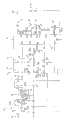
图3是图1中充电器的充电电路的电路图;Fig. 3 is a circuit diagram of the charging circuit of the charger in Fig. 1;
图4是图1中充电器的工作流程图;Fig. 4 is the working flowchart of charger among Fig. 1;
图5是图1中充电器的充电方法的流程图;Fig. 5 is a flow chart of the charging method of the charger in Fig. 1;
图6是图5中充电方法判断电池是否需要充电的子流程图;Fig. 6 is a subflow chart of judging whether the battery needs to be charged by the charging method in Fig. 5;
图7是图5中充电方法检测是否有外接电源输入的子流程图;Fig. 7 is a subflow chart of whether the charging method detects whether there is an external power supply input in Fig. 5;
图8是本发明第二实施方式提供的充电器的充电电路的电路图。Fig. 8 is a circuit diagram of a charging circuit of a charger provided in a second embodiment of the present invention.
其中,in,
100.充电器 42.接收部 70.控制器供电模块100. Charger 42. Receiver 70. Controller power supply module
10.外接电源 50.转换模块 71.第一供电电路10.
20.电池 60.控制器 72.第二供电电路20.
30.开关组件 61.电池电压检测模块 73.第三供电电路30. Switch
31.手动开关 62.充电电压检测模块 74.受控部31.
32.电子开关 63.时钟电路 75.稳压模块32.
40.外接电源检测模块 64.指示模块 76.连接点40. External power
41.发光部 65.充电电流检测模块 77.连接点41.
78.电流输入线路 271.第一供电电路 Q1.三极管78.
79.连接点 272.第二供电电路 Q2、Q3.MOS管79.
80.主供电线路 278.电流输入线路 D1、D2.二极管80. Main
200.充电器 R1、R2.电阻 D3、D4.二极管200. Charger R1, R2. Resistor D3, D4. Diode
210.外接电源 R3、R4.电阻 D5、D9.二极管210. External power supply R3, R4. Resistor D5, D9. Diode
220.电池 R5、R6.电阻 D6、D7.发光二极管220. Battery R5, R6. Resistor D6, D7. Light-emitting diode
230.开关组件 R7、R8.电阻 D8.发光二极管230. Switch component R7, R8. Resistor D8. Light emitting diode
240.外接电源检测模块 R9、R10.电阻 KM.线圈240. External power supply detection module R9, R10. Resistor KM. Coil
250.转换模块 R11、R12.电阻 C1、C2.电容250. Conversion module R11, R12. Resistance C1, C2. Capacitance
260.控制器 R13、R14.电阻 C3、C4.电容260. Controller R13, R14. Resistor C3, C4. Capacitor
270.控制器供电模块 R15、R16.电阻 Z1.稳压管270. Controller power supply module R15, R16. Resistor Z1. Regulator tube
具体实施方式Detailed ways
请参见图1,为本发明第一实施方式提供的一种充电器100的工作状态示意图。充电器100可以利用外接电源10向电池20充电。Please refer to FIG. 1 , which is a schematic diagram of a working state of a
外接电源10可以为交流电源或直流电源,其电能来源可以为市电或其他商用或民用发电机发出的电能,在本实施方式中,外接电源10为交流电源,电能来源为市电。The
电池20为可充电电池,如:镍镉电池、锂电池、铅酸电池以及镍氢电池等等,在本实施方式中,其为铅酸电池。The
可以理解,电池20并不限于普通意义上的单节电池,其包括具有若干电池的电池包。It can be understood that the
请参阅图2,其为充电器100的充电电路的示意框图。充电器100的充电电路具有一个与外接电源10和电池20连接的主供电线路80,在主供电线路80具有开关组件30、外接电源检测模块40、转换模块50、控制器60和控制器供电模块70。开关组件30控制充电器100与外接电源10连接的通断,外部电源检测模块40与开关组件30连接,检测是否有外接电源10输入,并能够向控制器60发送检测信号。转换模块50能够将外接电源10输入的电压,转换成适宜充电器100工作的电压。控制器60控制充电器100对电池20充电,并具有休眠状态和工作状态。控制器供电模块70获取外接电源10或电池20的电能向控制器60供电,并满足休眠状态和工作状态不同的用电需求。Please refer to FIG. 2 , which is a schematic block diagram of the charging circuit of the
请一并参阅图3,其为充电器100的充电电路的电路图。开关组件30设置于靠近主供电线路80与外接电源10连接的位置,其包括相并联的一个手动开关31和一个电子开关32。Please also refer to FIG. 3 , which is a circuit diagram of the charging circuit of the
手动开关31为一个非自锁机械开关,当手动开关31被按下,其连接的电路导通,当施加的外力撤销时,手动开关31自动断开。The
电子开关32可以为继电器、三极管或其他可控制具备通断功能的电子元件,在本实施方式中,其为一个继电器。该继电器主要包括一个线圈KM、三极管Q1、电阻R11、R12。三极管Q1为一个NPN型三极管,其基极通过电阻R11与控制器60连接。电阻R12与三极管Q1的基极和发射极相并联。线圈KM与三极管Q1的集电极相电性连接,以及与控制器供电模块70相电性连接。The
当控制器60控制电子开关32闭合时,会向三极管Q1的基极提供一个高电平,从而使三极管Q1导通,线圈KM产生磁力,进而使所述继电器吸合,实现其连接的电路导通。When the
外接电源检测模块40用于检测是否有外接电源10的电能输入,其与开关组件30以及控制器60连接,并能够向控制器60发送检测信号。外接电源检测模块40可以为一个采样电路、一个光耦电源检测电路或由多个电阻组成的检测电路,在本实施方式中,其为一个光耦电源检测电路。外接电源检测模块40包括发光部41和接收部42,发光部41包括相互并联且反向的发光二极管D8和二极管D9,并通过一个电阻R13与开关组件30连接,当开关组件30导通且外接电源10输入电能时,发光部41发出光线。接收部42为一个光敏三极管,其接收所述光线而导通向控制器60发出检测信号。The external power
转换模块50设置于主供电线路80中,将外接电源10经过主供电线路80输入的电压进行转换,以适合对电池20进行充电。转换模块50可以为一个AC/DC转换电路,也可以为一个DC/DC转换电路,也可以兼具AC/DC转换电路和DC/DC转换电路,在本实施方式中,其为一个AC/DC转换电路,将外接电源10输入的交流电转换成直流电。The
可以理解,转换模块50还可以设置具备对电池20恒流充电和恒压充电的功能,由于限于篇幅,且为本领域公知技术,在此不做详细介绍。It can be understood that the
控制器供电模块70包括一个第一供电电路71、一个第二供电电路72以及一个第三供电电路73。当没有外接电源10输入时,第一供电电路71在控制器60的控制下能够获取电池20的电能向控制器60供电,第二供电电路72直接获取电池20的电能向控制器60供电,第三供电电路73不能向控制器60供电;当有外接电源10输入时,控制器60电能来源仅为外接电源10。The controller
第一供电电路71与第二供电电路72具有相同的电流输入线路78,并且电流输入线路78与主供电线路80相电性连接,形成一个连接点79,且连接点79位于主供电线路80靠近电池20的位置,在连接点79与转换模块50之间设置有一个二极管D1,防止电池20的电流流入转换模块50。The first
第一供电电路71主要包括一个受控模块74和一个稳压模块75。受控模块74用于接受控制器60的控制,使第一供电电路71具有两个状态,即通电状态和断电状态,进而实现控制第一供电电路71是否向控制器60供电。The first
受控模块74包括电阻R4、MOS管Q3、电容C1、电阻R2、电阻R1以及MOS管Q2。MOS管Q3与电容C1相并联后与MOS管Q2的栅极连接,MOS管Q3的栅极经过电阻R4与控制器60连接,电阻R1与MOS管的源极和栅极相并联。当电池20接入充电器100后的瞬间内,由于电容C1充电相当于短路,因此电流能够流经电阻R1为MOS管Q2提供一个开启电压,使MOS管Q2导通,使第一供电电路71处于通电状态,电流经过稳压模块75进入控制器60,此时控制器60会向MOS管Q3的栅极提供一个电压,使其导通,从而维持第一供电电路71的通电状态。当需要第一供电电路71进入断电状态时,控制器60停止向MOS管Q3提供电压,则受控模块74不再形成通路,则MOS管Q2的栅极不再有电压输入,则电流无法通过MOS管Q3,此时第一供电电路71为断电状态。The controlled
可以理解,MOS管Q2、Q3还可以替换成其他具有电路通断控制的电子元件,如三极管、继电器等,在此限于篇幅,不进行详细列举,但只要其实现的功能和效果与本发明相同或相近似,均应涵盖于本发明保护范围内。It can be understood that the MOS tubes Q2 and Q3 can also be replaced with other electronic components with circuit on-off control, such as triodes, relays, etc., which are not listed in detail here due to space limitations, but as long as their functions and effects are the same as those of the present invention Or similar, all should be covered within the protection scope of the present invention.
稳压模块75为一个DC/DC转换电路,将第一供电电路71的电压转换成适合控制器60的直流电压并供给控制器60。当没有外接电源10输入时,此时第一供电电路71获取电池20的电能向控制器60供电,稳压模块75会将电池20输入的电压进行降压以适合控制器60,并能够持续稳定的保持输出该电压。在本实施方式中,假设电池20的电压为28V并在不断下降,而控制器60的工作电压为5V,则稳压模块75会将电池20提供的电压降至5V后,再提供给控制器60。当有外接电源10输入时,由于经过转换模块50转换输出的直流电的电压可能过高,如果直接向控制器60供电,则可能烧毁控制器60,此时,稳压模块75会对转换模块50输出的电流进行降压,并且使其更加稳定,以适合向控制器60供电。The
第二供电电路72中仅设置有一个电阻R10,且第二供电电路72的带负载能力小于第一供电电路71的带负载能力,即第一供电电路71能够驱动更多的电路元件。电阻R10可以设置成1M、1.5M或2M等等,在本实施方式中,其阻值为1M。第二供电电路72与第一供电电路71具有一个连接点76,二者连接后共同接入控制器60的电源输入端子。连接点76位于稳压模块75与控制器60之间,且为了防止在第一供电电路71处于断电状态时,电流会流向稳压模块75,在连接点76与稳压模块75之间设置一个二极管D5。Only one resistor R10 is provided in the second
当控制器60仅由第二供电电路72供电时,由于供电电流较小,且不够稳定,控制器60不会进行数据比较或判断之类的工作,能够进入并维持休眠状态,当其被唤醒时能够控制受控模块74使第一供电电路71进入通电状态,进而能够控制电子开关32闭合。When the
可以理解,为了使第二供电电路72向控制器60供电更加稳定,且防止第二电路中瞬时电压过高烧毁控制器60,可以在连接点76处连接一个稳压管Z1,此时第二供电电路72通过电阻R10和稳压管Z1串联向控制器60供电,由于电阻R10阻止大,且产生压降较大,致使稳压管Z1的输出电压小于其额定电压,从而实现流向控制器60的电流较小且稳定。另外,第二供电电路72通过与稳压管Z1并联设置一个电容C2,以满足控制器60从睡眠状态被唤醒时,瞬时内对电能需求激增的需要,防止因供电不足,导致控制器60死机。It can be understood that in order to make the power supply from the second
第三供电电路73能够利用外接电源10的电能向控制器60供电,其直接与主供电线路80连接,且连接点位于经转换模块50将外接电能转换成直流电能之后的部分。The third
第三供电电路73上设置有稳压模块,即DC/DC转换电路,为了实现电路优化,第三供电电路73和第一供电电路71可以共用一个稳压模块75,即第一供电电路71与第三供电电路73连接后再与稳压模块75连接,从而形成一个连接点77,并且在第一供电电路71靠近连接点77的位置设置二极管D3,以及在第三供电电路73靠近连接点77的位置设置二极管D2,限定电流的方向,避免第三供电电路73的电流流入第一供电电路71,或者第一供电电路71的电流流入第三供电电路73。为了防止电路接通瞬间,电路中电流过大烧毁稳压模块75,可以在连接点77与稳压模块75之间设置电阻R9,以保护稳压模块75。The third
可以理解,转换模块50可以具有两个正极输出端,且该两个输出端的输出电压不同,一个适用于用于给电池20充电,另一个适用于用于向控制器60供电,此时第三供电电路73直接与转换模块50给控制器60供电的输出端连接,如此,第三供电电路73可以不连接稳压模块75,直接向控制器60供电。It can be understood that the
第一供电电路71、第二供电电路72以及第三供电电路73向控制器60供电情况如下表一。The power supply conditions of the first
表一Table I

如序号1当没有外接电源10和电池20接入充电器100时,充电器100不会进行任何工作;如序号2和3当有外接电源10接入而无电池20时,控制器60不会控制接通电子开关32,此时点动手动开关31,会通过第三供电电路73向控制器60供电,但控制器60因没有发现电池20而不会进行工作。For example, when there is no
如序号4、5、6、7和8所示,当没有外接电源10接入而电池20装入充电器100时,第一供电电路71和第二供电电路72均向控制器60供电(如序号4),且第一供电电路71的供电电流大于第二供电回路72的供电电流,控制器60判断电池20是否需要充电,当不需要充电时,控制器60不会控制电子开关32接通,当电池20需要充电时(如序号5),则控制器60控制电子开关32接通,并通过外接电源检测模块40检测是否存在外接电源10输入,此时若没有发现外接电源10输入,则控制器60使第一供电电路71断电(如序号6),并断开电子开关32,仅由第二供电电路72进行供电。控制器60每每间隔一段时间接通一次第一供电电路71,并控制电子开关32接通一次(如序号7),判断是否有外接电源10输入。As shown in serial numbers 4, 5, 6, 7 and 8, when there is no
如序号8所示,当发现有外接电源10输入时,则控制电子开关32接通,并控制充电器100开始对电池20充电,此时第三供电回路73接通并向控制器60供电。由于线路长度原因,导致在连接点77处第三供电电路73的电压高于第一供电电路71的电压,因此,第一供电电路71在第三供电电路73导通后,便不再向控制器60供电。As shown in number 8, when an
如序号9所示,当电池20充满后,控制器60控制电子开关32断开,此时控制器60仅由第二供电电路72供电,充电器100不会消耗外接电源10的电能,且因为第二供电电路72供电电流较小,其消耗电池20的电能也非常少,从而实现整个充电器100非常节省电能。As shown in serial number 9, when the
如序号10所示,当电池20充满后,每间隔一段时间控制器60控制第一供电电路71接通一次,此时控制器60判断电池20是否需要充电,如果需要则重复前述功能,不需要则控制第一供电电路71停止供电。As shown in
如序号11所示,当外接电源10和电池20均接入充电器100,在控制器60尚未做出相应进行对电池20充电的时间内,如果手动开关31被接通,此时充电器100立即开始对电池20充电,并控制电子开关32闭合,从而实现了快速响应充电的功能。如果电池20装入充电器100时,已经过放电甚至完全放电,其可能没有足够的电能完成前述序号7和8的功能,即控制器60无法提供足够的电能使电子开关32接通,此时如果没有闭合手动开关31,则充电器100无法开始对电池20进行充电,若闭合手动开关31,则外部电源10会通过第三供电电路73向控制器60供电,从而控制器60能够控制接通电子开关32,即使此时断开手动开关31,电能也会从电子开关32进入第三供电电路73,从而确保对控制器60进行供电,进而能够实现整个充电器100对电池20进行充电。As shown in serial number 11, when both the
可以理解,充电器100还可以具有一个第四供电电路,所述第四供电电路具有一个纽扣电池,其将所述纽扣电池的电能供应给控制器60,为控制器60提供休眠状态下的电能,并可以使控制器60接通第一供电电路71。此时充电器100可以省去第二供电电路72,也可以四个向控制器60供电的供电电路并存。It can be understood that the
控制器60用于控制充电器100向电池20充电,其连接有一个电池电压检测模块61、充电电压检测模块62、时钟电路63、指示模块64以及充电电流检测模块65。控制器60内部还集成有看门狗电路,用于在控制器60进入休眠状态时,唤醒控制器60。The
电池电压检测模块61与控制器供电模块70连接,当电池20接入充电器100后,检测电池20的电压,并向控制器60反馈其检测信息,由控制器60进行运算得出电池20的电压值。The battery
充电电压检测模块62用于在充电器100为电池20充电过程中,检测充电电压,并向控制器60反馈其检测信息,由控制器60进行运算得出充电电压。The charging
时钟电路63用于给控制器60提供时钟源,并能够从控制器60获取电能,以维持该时钟电路63的工作。The
可以理解,时钟电路63为一个外接低频时钟电路,当控制器60进入休眠状态时,会停止给时钟电路63电能供应,从而节省了电能。It can be understood that the
指示模块64包括若干发光二极管,其在控制器60的控制下发光或者改变发光颜色,发光颜色的变化,可以用来表示充电器100的工作状态或者电池20是否已经被充满。在本实施方式中,设置二个发光二极管D6、D7,并分别发出红色和绿色两种颜色的光线。LED的状态,对应充电器的状态如下表二所示。The
表二Table II

控制器60从控制器供电模块70获取电能,能够接收外接电源检测模块40发出的检测信号,并根据所述检测信号判断是否有外接电源10的输入,能够向电子开关32以及控制器供电模块70发出控制信号,并且能够向时钟电路63以及指示模块64提供电能。The
可以理解,在控制器60根据外接电源检测模块40发出的检测信号判断是否有外接电源10的输入时,会因外接电源检测模块40的具体组成不同,导致判断方式有所不同,比如,外接电源检测模块40可以为采样电路,即其获取电池20的电能工作,并对外接电源10的输入进行采样检测,当没有检测到外接电源10的输入时,其输出低电平给控制器60,当检测到外接电源10的输入时,其输出高电平给控制器60,相对于控制器60,外接电源检测模块40输出的低电平或高电平即为检测信号。在本实施方式中,外接电源检测模块40为光耦电源检测电路,当有外接电源10的输入时,外接电源检测模块40输出的检测信号为电信号,当没有外接电源10的输入时,外接电源检测模块40输出的检测信号为空值,即其不发出电信号,控制器60根据接收到电信号或空值,判断出是否有外接电源10的输入。当然,控制器60通过外接电源检测模块40得出是否有外接电源10输入的技术方案并不局限于此,因限于篇幅,再次不进行穷举,但只要其采用的技术以及实现的效果与本发明相同或相似,均应涵盖于本发明保护范围内。It can be understood that when the
请参阅图4,为控制器60控制充电器100对电池20充电的工作流程图。Please refer to FIG. 4 , which is a flow chart of the
当电池20装入充电器100,第一供电电路71和第二供电电路72均从电池20获取电能向控制器60供电,控制器60开始工作,其维持第一供电电路71处于通电状态,并通过电池电压检测模块61提供的检测数据运算得出电池电压值,并通过与控制器60内部一个预设电压值比较判断电池是否需要充电,在本实施方式中,举例为假设所述预设电压值为26V,当控制器60发现电池20的电压大于26V,则认为电池20不需要充电,当控制器60发现电池电压值小于或等于26V,则认为电池20需要充电。When the
当电池20不需要充电时,控制器60控制第一供电电路71进入断电状态,其仅由第二供电电路72供电,充电过程结束,控制器进入休眠状态;当检测到电池20需要充电时,控制器60控制电子开关32闭合,并通过外接电源检测模块40检测是否有外接电源10输入,当没有发现外接电源10,控制器60控制第一供电电路71进入断电状态,其仅由第二供电电路72供电,此时控制器60进入休眠状态,并且每间隔一段时间由其内部的看门狗电路唤醒一次,被唤醒后,其接通第一供电电路71,并随即控制电子开关32闭合一次,由外接电源检测电路40检测是否有外接电源10输入,当没有外接电源10输入时,再次进入休眠,并重复被唤醒检测外接电源10的步骤;当发现外接电源10输入,则开始对电池20充电。When the
可以理解,控制器60每间隔一段时间从休眠模式被唤醒,该时间间隔可以逐渐延长,如最初5分钟内每3秒控制器60被唤醒一次,并控制电子开关32闭合,检测是否有外接电源10,如果没有外接电源10,则在第6分钟至第10分钟改为30秒被唤醒一次,10分钟后改为每10分钟唤醒一次。当然,本发明并不限于在本实施方式中描述的唤醒控制器60的规律,本领域技术人员还可以做出其他改变,但只要其技术精髓与本发明相同或相近似,均应涵盖于本发明保护范围内。It can be understood that the
在充电过程中,控制器60通过获取电池电压检测模块61、充电电压检测模块62以及充电电流检测模块65检测到的数据,判断电池20是否已经充满,当然也可以仅仅根据电池电压、充电电压或充电电流中的一项数据,判断电池20是否已经充满。在本实施方式中,举例为仅仅根据充电电流判断电池20是否充满,在控制器60内设置一个预设电流值,比如为300mA,当控制器60对通过充电电流检测模块65检测到的数据进行运算后,得出的充电电流值如果大于300mA,则认为电池20没有充满,需要继续充电;当得出的充电电流值小于等于300mA,控制器60会认为电池20已经充满,则控制电子开关32断开,结束充电过程。During the charging process, the
可以理解,当电池20充满后,如果没有脱离充电器100,则充电器100会进入休眠状态,仅由第二供电电路72供电,此后控制器60每间隔一段时间被唤醒一次,接通第一供电电路71并检测电池电压,如果控制器60发现电池20需要充电,则其控制充电器100对电池20充电,如果电池20不需要充电,则其控制第一供电电路71断电,然后再次进入休眠状态。It can be understood that when the
与现有充电器相比较,充电器100采用了两个从电池20获取电能向控制器60供电的供电电路,第一供电电路71通过稳压模块75向控制器60提供的电能,使控制器60能够控制电子开关32以及进行检测电压或电流等工作,第二供电电路72设置有大电阻R10,从而电流较小,且仅仅通过一个稳压管Z1进行稳压,可以使控制器60维持在休眠状态,并能够使其被唤醒,以及接通第一供电电路71。由于当控制器60进入休眠状态时,仅由第二供电电路72供电,避免了第一供电电路71中多个电子元件的静态耗电,特别是避免了稳压模块75的耗电,节省了电池20的电能,也避免了电池20进一步过放电的风险。Compared with the existing charger, the
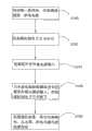
请参阅图5,其为本发明第一实施方式提供的一种适用于充电器100的充电方法,该方法包括以下步骤。Please refer to FIG. 5 , which is a charging method suitable for the
步骤S110:当电池20装入充电器100,第一供电电路71和第二供电电路72获取电池20的电能向控制器60供电。Step S110 : when the
当电池20装入充电器100时,第一供电电路71和第二供电电路72会通电,此时控制器60开始工作,并控制第一供电电路71维持通电状态。When the
步骤S115:控制器60判断电池20是否需要充电。Step S115: The
控制器60通过对电池电压检测模块61检测的数据进行运算,得出电池电压,比较其与控制器60内部的预设电压值的大小关系,判断出电池20是否需要充电。The
步骤S119:若电池20不需要充电,控制器60控制第一供电电路71断电,仅由第二供电电路72向控制器60供电。Step S119: If the
随即控制器60会进入休眠状态,等待被其内部的看门狗电路唤醒。Then the
步骤S123:当电池20需要充电,控制器60控制电子开关32闭合,并由外接电源检测模块40检测外接电源10的输入。Step S123: When the
步骤S125:当外接电源检测模块40没有发现外接电源10的输入时,控制器60控制电子开关32断开,并控制第一供电电路71断电,仅由第二供电电路72向控制器60供电。Step S125: When the external power
当控制器60通过外接电源检测电路40没有发现外接电源10时,其控制第一供电电路71断电,仅由第二供电电路72供电,此时控制器60进入休眠状态。When the
步骤S127:每间隔一段时间,控制器60接通一次第一供电电路71,以及控制电子开关32闭合,并由外接电源检测模块40检测是否有外接电源10的输入。Step S127: At regular intervals, the
控制器60每间隔一段时间被唤醒一次,并接通第一供电电路71,随即控制电子开关32闭合一次,通过外接电源检测电路40检测是否有外接电源10输入。The
步骤S133:当有外接电源10输入时,充电器100开始对电池20充电。Step S133 : When the
步骤S139:当电池20被充满后,控制器60控制充电器100断开与外接电源10连接。Step S139 : When the
控制器60可以通过获取电池电压检测模块61、充电电压检测模块62以及充电电流检测模块65检测到的数据,判断电池20是否已经充满,当然也可以仅仅根据电池电压、充电电压或充电电流判断电池20是否已经充满。在本实施方式中,控制器60根据充电电流判断电池20是否充满,若电池20已经充满,则控制电子开关32断开,使充电器100断开与外接电源10的连接。The
步骤S141:控制器60每间隔一段时间,接通一次第一供电电路71,并重复前述步骤S115。Step S141: The
因为电池20存在自放电现象,如果其长时间安装在充电器100上,则控制器60会每间隔一段时间接通一次第一供电电路71,并通过电池电压检测模块61检测的数据,进行运算得出电池20的电压值,判断其是否需要充电。Because the
可以理解,前述为一个重复循环的充电方法,仅当电池20被移除充电器100,该充电方法结束。It can be understood that the foregoing charging method is a repeated cycle, and the charging method ends only when the
可以理解,请一并参阅图6,前述步骤S115还包括如下子步骤。It can be understood that, please refer to FIG. 6 together, the aforementioned step S115 also includes the following sub-steps.
步骤S150:控制器60控制第一供电电路71通电。Step S150: the
步骤S152:电池电压检测模块61检测电池10的电压,并反馈给控制器60检测数据;Step S152: the battery
步骤S154:控制器60根据检测数据得出电池电压值,将所述电池电压值与一个预设电压值比较;Step S154: the
步骤S156:当所述电池电压值大于或等于所述预设电压值时,控制器60控制第一供电电路71断电,仅由第二供电电路72向控制器60供电。Step S156: When the battery voltage value is greater than or equal to the preset voltage value, the
步骤S158:当所述电池电压值小于所述预设电压值时,控制器60控制充电器100向电池20充电。Step S158: When the battery voltage value is lower than the preset voltage value, the
可以理解,请一并参阅图7,前述步骤S127还包括如下子步骤。It can be understood that, please refer to FIG. 7 together, the aforementioned step S127 also includes the following sub-steps.
步骤S160:每间隔一段时间,控制器60接通第一供电电路71。Step S160: the
控制器60每间隔一段时间,被唤醒一次,随即其接通第一供电电路71。The
步骤S162:控制器60控制电子开关32闭合;Step S162: the
控制器60在第一供电电路71的电力供应下,接通电子开关32。The
步骤S164:外接电源检测模块40检测是否有外接电源10输入。Step S164: The external power
步骤S166:当外接电源检测模块40没有检测到外接电源10的输入时,控制器60控制电子开关32断开。Step S166: When the external power
步骤S168:控制器60控制第一供电电路71断电,仅由第二供电电路72向控制器60供电。Step S168: the
此时,控制器60进入休眠状态,等待下一次被唤醒。At this time, the
请参阅图8,其为本发明第二实施方式提供的充电器200的电路图。充电器200能够利用外接电源210向电池220充电,其具有一个与外接电源210连接的主供电线路280,在主供电线路280上连接有开关组件230、外接电源检测模块240、转换模块250、控制器260和控制器供电模块270。Please refer to FIG. 8 , which is a circuit diagram of a charger 200 provided in a second embodiment of the present invention. The charger 200 can use the
充电器200与第一实施方式提供的充电器100的功能及结构基本相同,其不同之处在于:控制器供电模块270仅包括第一供电电路271和第二供电电路272。The function and structure of the charger 200 are basically the same as those of the
当需要对电池220充电,且外接电源检测模块240发现外接电源210输入时,电流会沿着主供电线路280进入电流输入线路278,随即流经第一供电电路271和第二供电电路272向控制器260供电。在对电池220充电的过程中,控制器260会维持第一供电电路271处于通电状态,以保持控制器260能够得到持续稳定的电能供应。When the
与现有技术相比,本发明的充电器及其充电方法设置有第一供电电路和第二供电电路,当电池装入所述充电器,该二个供电电路均能够从所述电池获取电能向所述控制器供电,若此时没有所述外接电源输入到所述充电器中,所述控制器会控制所述第一供电电路断电,而仅由所述第二供电电路向所述控制器供电。由于第二供电电路的电阻较大,供电电流较小,致使耗费电池的电能非常少,从而避免使所述电池进一步过放电,有效防止所述充电器给电池造成损伤。Compared with the prior art, the charger and its charging method of the present invention are provided with a first power supply circuit and a second power supply circuit, and when a battery is loaded into the charger, the two power supply circuits can obtain electric energy from the battery supply power to the controller, if there is no external power input into the charger at this time, the controller will control the first power supply circuit to cut off the power, and only the second power supply circuit will supply power to the Controller power supply. Since the resistance of the second power supply circuit is relatively large and the supply current is relatively small, very little electric energy is consumed by the battery, thereby avoiding further over-discharging of the battery and effectively preventing damage to the battery by the charger.
本领域技术人员可以想到的是,本发明还可以有其他的实现方式,但只要其采用的技术精髓与本发明相同或相近似,或者任何基于本发明作出的变化和替换都在本发明的保护范围之内。Those skilled in the art can imagine that the present invention can also have other implementations, but as long as the technical essence it adopts is the same as or similar to the present invention, or any changes and replacements based on the present invention are protected by the present invention. within range.
Claims (10)
Priority Applications (2)
| Application Number | Priority Date | Filing Date | Title |
|---|---|---|---|
| CN2010101149104ACN102148512B (en) | 2010-02-05 | 2010-02-05 | Charger and charging method thereof |
| PCT/CN2011/070864WO2011095132A1 (en) | 2010-02-05 | 2011-01-31 | Charger |
Applications Claiming Priority (1)
| Application Number | Priority Date | Filing Date | Title |
|---|---|---|---|
| CN2010101149104ACN102148512B (en) | 2010-02-05 | 2010-02-05 | Charger and charging method thereof |
Related Child Applications (1)
| Application Number | Title | Priority Date | Filing Date |
|---|---|---|---|
| CN201110118400.9ADivisionCN102148526B (en) | 2010-02-05 | 2010-02-05 | Charger |
Publications (2)
| Publication Number | Publication Date |
|---|---|
| CN102148512Atrue CN102148512A (en) | 2011-08-10 |
| CN102148512B CN102148512B (en) | 2013-10-16 |
Family
ID=44422579
Family Applications (1)
| Application Number | Title | Priority Date | Filing Date |
|---|---|---|---|
| CN2010101149104AActiveCN102148512B (en) | 2010-02-05 | 2010-02-05 | Charger and charging method thereof |
Country Status (1)
| Country | Link |
|---|---|
| CN (1) | CN102148512B (en) |
Cited By (11)
| Publication number | Priority date | Publication date | Assignee | Title |
|---|---|---|---|---|
| CN102749857A (en)* | 2012-06-15 | 2012-10-24 | 天津市亚安科技股份有限公司 | Cradle head energy saving device and cradle head energy-saving control method |
| CN103199572A (en)* | 2012-01-07 | 2013-07-10 | 苏州宝时得电动工具有限公司 | Charging base station and charging method |
| CN103701180A (en)* | 2014-01-10 | 2014-04-02 | 济南大学 | Electric vehicle charging APO (Automatic Power Off) device |
| CN104124718A (en)* | 2013-04-27 | 2014-10-29 | 宏碁股份有限公司 | Power supply device and power supply method |
| CN104617643A (en)* | 2015-03-09 | 2015-05-13 | 广东欧珀移动通信有限公司 | Charging method, equipment to be charged, power supply equipment and charging system |
| CN106300482A (en)* | 2015-06-05 | 2017-01-04 | 西安中兴新软件有限责任公司 | A kind of charger and control method thereof |
| CN106494418A (en)* | 2016-12-07 | 2017-03-15 | 中车株洲电力机车有限公司 | A kind of low-voltage control circuit of train aid system and train |
| CN107546802A (en)* | 2017-09-08 | 2018-01-05 | 广州明美新能源有限公司 | A kind of high-power multi-series and parallel li-ion cell protection system |
| CN110338733A (en)* | 2019-07-15 | 2019-10-18 | 浙江帅康电气股份有限公司 | An independent water catalyst generator and its cleaning device and electric appliance |
| CN110797948A (en)* | 2019-11-18 | 2020-02-14 | 深圳市群芯科创电子有限公司 | Fast charging control circuit |
| CN113644708A (en)* | 2021-07-23 | 2021-11-12 | 深圳拓邦股份有限公司 | Equipment charging management system, device, method and storage medium |
Citations (5)
| Publication number | Priority date | Publication date | Assignee | Title |
|---|---|---|---|---|
| JPH04347541A (en)* | 1991-05-24 | 1992-12-02 | Mitsuba Electric Mfg Co Ltd | Power supply circuit for computer |
| US20050132108A1 (en)* | 2003-12-15 | 2005-06-16 | Chien-Ju Lee | Current limiting device and a PDA utilizing the current limiting device |
| CN101452264A (en)* | 2007-07-16 | 2009-06-10 | 周先谱 | Power control device for zero power consumption standby and safety operation |
| CN101630859A (en)* | 2009-08-14 | 2010-01-20 | 深圳和而泰智能控制股份有限公司 | Mobile terminal charger |
| CN201616691U (en)* | 2010-02-05 | 2010-10-27 | 苏州宝时得电动工具有限公司 | Charger |
- 2010
- 2010-02-05CNCN2010101149104Apatent/CN102148512B/enactiveActive
Patent Citations (5)
| Publication number | Priority date | Publication date | Assignee | Title |
|---|---|---|---|---|
| JPH04347541A (en)* | 1991-05-24 | 1992-12-02 | Mitsuba Electric Mfg Co Ltd | Power supply circuit for computer |
| US20050132108A1 (en)* | 2003-12-15 | 2005-06-16 | Chien-Ju Lee | Current limiting device and a PDA utilizing the current limiting device |
| CN101452264A (en)* | 2007-07-16 | 2009-06-10 | 周先谱 | Power control device for zero power consumption standby and safety operation |
| CN101630859A (en)* | 2009-08-14 | 2010-01-20 | 深圳和而泰智能控制股份有限公司 | Mobile terminal charger |
| CN201616691U (en)* | 2010-02-05 | 2010-10-27 | 苏州宝时得电动工具有限公司 | Charger |
Cited By (15)
| Publication number | Priority date | Publication date | Assignee | Title |
|---|---|---|---|---|
| CN103199572B (en)* | 2012-01-07 | 2016-08-03 | 苏州宝时得电动工具有限公司 | charging base station and charging method |
| CN103199572A (en)* | 2012-01-07 | 2013-07-10 | 苏州宝时得电动工具有限公司 | Charging base station and charging method |
| CN102749857A (en)* | 2012-06-15 | 2012-10-24 | 天津市亚安科技股份有限公司 | Cradle head energy saving device and cradle head energy-saving control method |
| CN104124718A (en)* | 2013-04-27 | 2014-10-29 | 宏碁股份有限公司 | Power supply device and power supply method |
| CN103701180A (en)* | 2014-01-10 | 2014-04-02 | 济南大学 | Electric vehicle charging APO (Automatic Power Off) device |
| CN104617643B (en)* | 2015-03-09 | 2018-01-16 | 广东欧珀移动通信有限公司 | Charging method, charging equipment, power supply unit and charging system |
| CN104617643A (en)* | 2015-03-09 | 2015-05-13 | 广东欧珀移动通信有限公司 | Charging method, equipment to be charged, power supply equipment and charging system |
| CN106300482A (en)* | 2015-06-05 | 2017-01-04 | 西安中兴新软件有限责任公司 | A kind of charger and control method thereof |
| CN106494418A (en)* | 2016-12-07 | 2017-03-15 | 中车株洲电力机车有限公司 | A kind of low-voltage control circuit of train aid system and train |
| CN106494418B (en)* | 2016-12-07 | 2018-08-03 | 中车株洲电力机车有限公司 | A kind of low-voltage control circuit and train of train auxiliary system |
| CN107546802A (en)* | 2017-09-08 | 2018-01-05 | 广州明美新能源有限公司 | A kind of high-power multi-series and parallel li-ion cell protection system |
| CN110338733A (en)* | 2019-07-15 | 2019-10-18 | 浙江帅康电气股份有限公司 | An independent water catalyst generator and its cleaning device and electric appliance |
| CN110797948A (en)* | 2019-11-18 | 2020-02-14 | 深圳市群芯科创电子有限公司 | Fast charging control circuit |
| CN110797948B (en)* | 2019-11-18 | 2021-10-08 | 深圳市群芯科创电子有限公司 | Fast charging control circuit |
| CN113644708A (en)* | 2021-07-23 | 2021-11-12 | 深圳拓邦股份有限公司 | Equipment charging management system, device, method and storage medium |
Also Published As
| Publication number | Publication date |
|---|---|
| CN102148512B (en) | 2013-10-16 |
Similar Documents
| Publication | Publication Date | Title |
|---|---|---|
| CN102148512B (en) | Charger and charging method thereof | |
| USRE50619E1 (en) | Emergency power source | |
| CN103000964B (en) | Controller of battery management system | |
| CN102148526B (en) | Charger | |
| CN205793566U (en) | A kind of single live wire switch | |
| CN204391863U (en) | Automatic power-off circuit and automatic power-off device for full storage battery of storage battery car | |
| JP2020510396A5 (en) | ||
| CN103236733B (en) | Electric bicycle charging device with functions of delaying time and powering off | |
| CN107895997B (en) | Energy system with multi-energy composite power supply | |
| CN105119349A (en) | General smart battery charger | |
| CN103427821B (en) | Power management device realizing zero standby current | |
| CN101752881B (en) | Uninterruptible power supply with low power consumption | |
| CN103368235B (en) | Nickel-metal hydride battery charge-discharge circuit in uninterruptible power supply | |
| CN105262192A (en) | Vehicle-mounted direct current system capable of stabilizing power supply and charging batteries | |
| CN201616699U (en) | Charger | |
| CN102148524B (en) | Charger | |
| CN103326426A (en) | Electromobile charger self-outage device | |
| CN203933057U (en) | A kind of portable multi-function portable power source | |
| CN201616691U (en) | Charger | |
| WO2011095132A1 (en) | Charger | |
| CN206195406U (en) | Energy -conserving formula electric vehicle charging electrical socket of autotomying | |
| CN201298743Y (en) | Energy-saving device for moped charger | |
| CN211830278U (en) | Charging management system for rechargeable battery | |
| CN202634014U (en) | Efficient and safe battery charger | |
| CN202488846U (en) | An intelligent LED emergency lighting device |
Legal Events
| Date | Code | Title | Description |
|---|---|---|---|
| C06 | Publication | ||
| PB01 | Publication | ||
| C10 | Entry into substantive examination | ||
| SE01 | Entry into force of request for substantive examination | ||
| C14 | Grant of patent or utility model | ||
| GR01 | Patent grant |