CN102142950A - Communication device and communication method - Google Patents
Communication device and communication methodDownload PDFInfo
- Publication number
- CN102142950A CN102142950ACN2011100265507ACN201110026550ACN102142950ACN 102142950 ACN102142950 ACN 102142950ACN 2011100265507 ACN2011100265507 ACN 2011100265507ACN 201110026550 ACN201110026550 ACN 201110026550ACN 102142950 ACN102142950 ACN 102142950A
- Authority
- CN
- China
- Prior art keywords
- data
- modulation
- subcarriers
- outputs
- chips
- Prior art date
- Legal status (The legal status is an assumption and is not a legal conclusion. Google has not performed a legal analysis and makes no representation as to the accuracy of the status listed.)
- Granted
Links
Images


Classifications
- H—ELECTRICITY
- H04—ELECTRIC COMMUNICATION TECHNIQUE
- H04L—TRANSMISSION OF DIGITAL INFORMATION, e.g. TELEGRAPHIC COMMUNICATION
- H04L5/00—Arrangements affording multiple use of the transmission path
- H04L5/0001—Arrangements for dividing the transmission path
- H04L5/0014—Three-dimensional division
- H04L5/0016—Time-frequency-code
- H—ELECTRICITY
- H04—ELECTRIC COMMUNICATION TECHNIQUE
- H04B—TRANSMISSION
- H04B1/00—Details of transmission systems, not covered by a single one of groups H04B3/00 - H04B13/00; Details of transmission systems not characterised by the medium used for transmission
- H04B1/69—Spread spectrum techniques
- H04B1/692—Hybrid techniques using combinations of two or more spread spectrum techniques
- H—ELECTRICITY
- H04—ELECTRIC COMMUNICATION TECHNIQUE
- H04L—TRANSMISSION OF DIGITAL INFORMATION, e.g. TELEGRAPHIC COMMUNICATION
- H04L27/00—Modulated-carrier systems
- H04L27/0008—Modulated-carrier systems arrangements for allowing a transmitter or receiver to use more than one type of modulation
- H—ELECTRICITY
- H04—ELECTRIC COMMUNICATION TECHNIQUE
- H04L—TRANSMISSION OF DIGITAL INFORMATION, e.g. TELEGRAPHIC COMMUNICATION
- H04L27/00—Modulated-carrier systems
- H04L27/32—Carrier systems characterised by combinations of two or more of the types covered by groups H04L27/02, H04L27/10, H04L27/18 or H04L27/26
- H04L27/34—Amplitude- and phase-modulated carrier systems, e.g. quadrature-amplitude modulated carrier systems
- H04L27/3405—Modifications of the signal space to increase the efficiency of transmission, e.g. reduction of the bit error rate, bandwidth, or average power
- H—ELECTRICITY
- H04—ELECTRIC COMMUNICATION TECHNIQUE
- H04L—TRANSMISSION OF DIGITAL INFORMATION, e.g. TELEGRAPHIC COMMUNICATION
- H04L5/00—Arrangements affording multiple use of the transmission path
- H04L5/003—Arrangements for allocating sub-channels of the transmission path
- H04L5/0058—Allocation criteria
- H04L5/006—Quality of the received signal, e.g. BER, SNR, water filling
- H—ELECTRICITY
- H04—ELECTRIC COMMUNICATION TECHNIQUE
- H04L—TRANSMISSION OF DIGITAL INFORMATION, e.g. TELEGRAPHIC COMMUNICATION
- H04L5/00—Arrangements affording multiple use of the transmission path
- H04L5/0001—Arrangements for dividing the transmission path
- H04L5/0028—Variable division
- H—ELECTRICITY
- H04—ELECTRIC COMMUNICATION TECHNIQUE
- H04L—TRANSMISSION OF DIGITAL INFORMATION, e.g. TELEGRAPHIC COMMUNICATION
- H04L5/00—Arrangements affording multiple use of the transmission path
- H04L5/003—Arrangements for allocating sub-channels of the transmission path
- H04L5/0044—Allocation of payload; Allocation of data channels, e.g. PDSCH or PUSCH
- H—ELECTRICITY
- H04—ELECTRIC COMMUNICATION TECHNIQUE
- H04L—TRANSMISSION OF DIGITAL INFORMATION, e.g. TELEGRAPHIC COMMUNICATION
- H04L5/00—Arrangements affording multiple use of the transmission path
- H04L5/003—Arrangements for allocating sub-channels of the transmission path
- H04L5/0058—Allocation criteria
- H04L5/0064—Rate requirement of the data, e.g. scalable bandwidth, data priority
Landscapes
- Engineering & Computer Science (AREA)
- Signal Processing (AREA)
- Computer Networks & Wireless Communication (AREA)
- Quality & Reliability (AREA)
- Mobile Radio Communication Systems (AREA)
Abstract
Translated fromChinese
Description
Translated fromChinese本申请为以下专利申请的分案申请:申请日为2004年8月18日,申请号为200480022519.4,发明名称为《无线发送装置以及无线发送方法》。This application is a divisional application of the following patent application: the filing date is August 18, 2004, the application number is 200480022519.4, and the title of the invention is "Wireless Transmission Device and Wireless Transmission Method".
技术领域technical field
本发明涉及无线发送装置以及无线发送方法。The present invention relates to a wireless transmission device and a wireless transmission method.
背景技术Background technique
近年来,作为高速传输大量数据的方法,OFDM(Orthogonal Frequency Division Multiple,正交频分多路复用)和CDMA相结合的系统被探讨研究。在OFDM和CDMA相结合的系统中,有将数据进行扩频而形成的码片按频率方向配置在副载波上的方式和按时间方向配置在副载波上的方式。In recent years, as a method of high-speed transmission of large amounts of data, a system combining OFDM (Orthogonal Frequency Division Multiple, Orthogonal Frequency Division Multiplexing) and CDMA has been studied. In a system combining OFDM and CDMA, there is a method of arranging chips formed by spreading data on subcarriers in the frequency direction and a method of arranging subcarriers in the time direction.
在频率方向上扩频时,因为多路径环境会引起频率选择性衰落,使频率方向的传播路径发生剧烈变动,所以虽然能够得到解扩时的频率分集效果,但是扩频码之间的正交性受到破坏,接收特性恶化。When spreading in the frequency direction, because the multipath environment will cause frequency selective fading, the propagation path in the frequency direction will change drastically, so although the frequency diversity effect during despreading can be obtained, the orthogonality between the spreading codes Sexuality is destroyed and reception characteristics deteriorate.
在时间轴方向上扩频时,与频率方向相比,因为时间轴方向的传播路径的变动相对而言较为缓和,所以虽然不能得到频率分集的效果,但是能够确保扩频码之间的正交性。可是,由于被分配到衰减较大的副载波上的数据的接收SNR(信噪比)非常小,发生完全错误的可能性较高。When spreading in the time axis direction, compared with the frequency direction, the variation of the propagation path in the time axis direction is relatively gentle, so although the effect of frequency diversity cannot be obtained, the orthogonality between spreading codes can be ensured. sex. However, since the reception SNR (Signal-to-Noise Ratio) of the data allocated to the subcarrier with large attenuation is very small, the possibility of complete error is high.
特别是使用16QAM(正交振幅调制)等复用调制进行码分复用时,由于扩频码之间的正交性被破坏而加剧接收性能的恶化,所以与频率轴方向的扩频相比,时间轴方向的扩频特性较好。Especially when multiplexing modulation such as 16QAM (Quadrature Amplitude Modulation) is used for code division multiplexing, since the orthogonality between spreading codes is destroyed and the deterioration of receiving performance is aggravated, compared with spreading in the frequency axis direction, , the spread spectrum characteristics in the direction of the time axis are better.
发明内容Contents of the invention
在现有装置中,无论哪种方法都各有利弊,通过OFDM和CDMA相结合来提高传输效率是个难题。In existing devices, no matter which method has its own advantages and disadvantages, it is a difficult problem to improve the transmission efficiency through the combination of OFDM and CDMA.
本发明的目的在于提供一种无线发送装置以及无线发送方法,该无线发送装置以及无线发送方法能够进行传输效率良好的通信。An object of the present invention is to provide a wireless transmission device and a wireless transmission method capable of performing communication with high transmission efficiency.
本发明的通信装置包括:调制单元,使用多个第一调制方式中的一个调制方式调制第一数据,使用多个第二调制方式中的一个调制方式调制第二数据,所述多个第二调制方式包含与所述第一调制方式的调制复用数不同的调制方式;以及配置单元,在时间轴方向上将经调制的所述第一数据配置在多个副载波上,在频率轴方向上将经调制的所述第二数据配置在多个副载波上。The communication device of the present invention includes: a modulating unit that uses one of multiple first modulation modes to modulate first data, uses one of multiple second modulation modes to modulate second data, and the multiple second modulation modes The modulation method includes a modulation method different from the modulation multiplexing number of the first modulation method; and the configuration unit configures the modulated first data on a plurality of subcarriers in the direction of the time axis, and in the direction of the frequency axis configuring the modulated second data on multiple subcarriers.
本发明的通信装置包括:接收单元,接收第一数据和第二数据,所述第一数据在时间轴方向上被配置在多个副载波上,且使用多个第一调制方式中的一个调制方式调制,所述第二数据在频率轴方向上被配置在多个副载波上,且使用多个第二调制方式中的一个调制方式调制,所述多个第二调制方式包含与所述第一调制方式的调制复用数不同的调制方式;以及解调单元,解调接收的所述第一数据和接收的所述第二数据。The communication device of the present invention includes: a receiving unit that receives first data and second data, the first data is arranged on a plurality of subcarriers in the direction of the time axis, and is modulated using one of the plurality of first modulation methods mode modulation, the second data is configured on a plurality of subcarriers in the direction of the frequency axis, and is modulated using one of a plurality of second modulation modes, and the plurality of second modulation modes include the same A modulation scheme with different modulation multiplexing numbers; and a demodulation unit that demodulates the received first data and the received second data.
本发明的通信方法包括以下步骤:使用多个第一调制方式中的一个调制方式调制第一数据,使用多个第二调制方式中的一个调制方式调制第二数据,所述多个第二调制方式包含与所述第一调制方式的调制复用数不同的调制方式;在时间轴方向上将经调制的所述第一数据配置在多个副载波上;以及在频率轴方向上将经调制的所述第二数据配置在多个副载波上。The communication method of the present invention includes the following steps: using one of multiple first modulation modes to modulate the first data, using one of multiple second modulation modes to modulate the second data, the multiple second modulation modes The method includes a modulation method different from the modulation multiplexing number of the first modulation method; the modulated first data is arranged on a plurality of subcarriers in the time axis direction; and the modulated first data is arranged in the frequency axis direction The second data of is configured on multiple subcarriers.
本发明的通信方法包括以下步骤:接收第一数据,所述第一数据在时间轴方向上被配置在多个副载波上,且使用多个第一调制方式中的一个调制方式调制;接收第二数据,所述第二数据在频率轴方向上被配置在多个副载波上,且使用多个第二调制方式中的一个调制方式调制,所述多个第二调制方式包含与所述第一调制方式的调制复用数不同的调制方式;以及解调接收的所述第一数据和接收的所述第二数据。The communication method of the present invention includes the following steps: receiving first data, the first data is configured on a plurality of subcarriers in the direction of the time axis, and is modulated by one of the plurality of first modulation methods; receiving the first data Two data, the second data is configured on a plurality of subcarriers in the direction of the frequency axis, and is modulated using one of the plurality of second modulation methods, the plurality of second modulation methods include the same as the first modulation method a modulation scheme with different modulation multiplexing numbers; and demodulating the received first data and the received second data.
本发明的无线通信装置包括:编码单元,对发送数据进行编码,生成信息位和奇偶校验位;扩频单元,将所述信息位和所述奇偶校验位乘上扩频码进行扩频;映射单元,将所述奇偶校验位经扩频而形成的码片配置在时间轴方向上,将所述信息位经扩频而形成的码片按频率方向和时间轴方向进行二维配置;以及发送单元,发送由所述映射单元配置后的各个码片。The wireless communication device of the present invention includes: a coding unit, which encodes the transmitted data, and generates information bits and parity bits; a spreading unit, which multiplies the information bits and the parity bits by a spreading code to spread the spectrum The mapping unit configures the chips formed by spreading the parity bits in the direction of the time axis, and configures the chips formed by spreading the information bits in a two-dimensional manner in the frequency direction and the direction of the time axis ; and a sending unit, sending each chip configured by the mapping unit.
本发明的无线通信装置包括:接收单元,接收使用多个副载波而发送的信号;解映单元,将奇偶校验位经扩频而形成的码片重新排列在时间轴方向上,将信息位经扩频而形成的码片按频率方向和时间轴方向进行二维的重新排列;解扩单元,对由所述解映单元重新排列的各个码片进行解扩;以及译码单元,根据解扩后的信息位和奇偶检验位对数据进行译码。The wireless communication device of the present invention includes: a receiving unit, which receives signals transmitted using a plurality of subcarriers; The chips formed by spreading are two-dimensionally rearranged according to the frequency direction and the time axis direction; the despreading unit despreads each chip rearranged by the demapping unit; and the decoding unit performs despreading according to the despreading unit The expanded information bits and parity bits decode the data.
本发明的无线通信方法包括:对发送数据进行编码,生成信息位和奇偶校验位;将所述信息位和所述奇偶校验位乘上扩频码进行扩频;将所述奇偶校验位经扩频而形成的码片配置在时间轴方向上,将所述信息位经扩频而形成的码片按频率方向和时间轴方向进行二维配置;以及发送配置后的各个码片。The wireless communication method of the present invention includes: encoding the transmission data to generate information bits and parity bits; multiplying the information bits and the parity bits by spreading codes to spread spectrum; The chips formed by spreading the bits are arranged in the time axis direction, and the chips formed by spreading the information bits are arranged two-dimensionally in the frequency direction and the time axis direction; and sending each arranged chips.
本发明的无线发送装置是一种发送由多个副载波组成的无线信号的无线发送装置,包括:使用第1调制方式将发送数据调制而得到第1调制数据,同时使用比上述第1调制方式高的调制复用数的第2调制方式将发送数据调制而得到第2调制数据的调制器;将上述第1调制数据扩频而得到多个第1码片,同时将上述第2调制数据扩频而得到多个第2码片的扩频器;以及将上述第1码片配置在频率方向上排列的多个第1副载波上,同时将上述第2码片配置在时间方向上排列的多个第2副载波上的映射器。The wireless transmission device of the present invention is a wireless transmission device for transmitting a wireless signal composed of a plurality of subcarriers, including: using a first modulation method to modulate the transmission data to obtain the first modulated data, and simultaneously using The second modulation method with a high modulation multiplexing number modulates the transmission data to obtain a modulator of the second modulated data; spreads the above-mentioned first modulated data to obtain a plurality of first chips, and simultaneously spreads the above-mentioned second modulated data A frequency spreader for obtaining a plurality of second chips; Mappers on multiple 2nd subcarriers.
根据本发明,能够进行传输效率良好的通信。According to the present invention, communication with good transmission efficiency can be performed.
附图说明Description of drawings
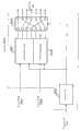
图1表示根据本发明实施方式1的无线通信装置结构的方框图。FIG. 1 is a block diagram showing the configuration of a wireless communication device according to Embodiment 1 of the present invention.
图2表示一例频率方向的信道变动的图。FIG. 2 shows an example of channel variation in the frequency direction.
图3表示一例时间轴上的信道变动的图。FIG. 3 shows an example of channel variation on the time axis.
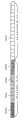
图4表示上述实施方式的无线通信装置的一例码片配置的图。FIG. 4 is a diagram showing an example of a chip arrangement of the wireless communication device according to the above-mentioned embodiment.
图5表示上述实施方式的无线通信装置的一例映射器结构的方框图。Fig. 5 is a block diagram showing an example of a mapper configuration of the wireless communication device according to the above-mentioned embodiment.
图6表示一例扩频后的数据的图。Fig. 6 is a diagram showing an example of spread data.
图7表示一例将数据配置在副载波上的图。FIG. 7 shows an example of arranging data on subcarriers.
图8表示根据本发明实施方法1的无线通信装置的结构方框图。FIG. 8 is a block diagram showing the structure of a wireless communication device according to Method 1 of the present invention.
图9表示上述实施方式的无线通信装置的一例解调器结构的方框图。FIG. 9 is a block diagram showing an example of a configuration of a demodulator of the wireless communication device according to the above-mentioned embodiment.
图10表示上述实施方式的无线通信装置的一例映射器结构的方框图。Fig. 10 is a block diagram showing an example of a mapper configuration of the wireless communication device according to the above-mentioned embodiment.
图11表示一例频率方向的信道变动的图。FIG. 11 shows an example of channel variation in the frequency direction.
图12表示上述实施方式的无线通信装置的一例码片配置的图。Fig. 12 is a diagram showing an example of a chip arrangement of the wireless communication device according to the above-mentioned embodiment.
图13表示上述实施方式的无线通信装置的一例解调器结构的方框图。Fig. 13 is a block diagram showing an example of a configuration of a demodulator of the wireless communication device according to the above-mentioned embodiment.
图14表示根据本发明实施方式2的无线通信装置结构的方框图。Fig. 14 is a block diagram showing the configuration of a wireless communication device according to Embodiment 2 of the present invention.
图15表示一例扩频后的数据的图。Fig. 15 is a diagram showing an example of spread data.
图16表示一例将数据配置在副载波上的图。FIG. 16 shows an example of arranging data on subcarriers.
图17表示根据本发明实施方式2的无线通信装置结构的方框图。Fig. 17 is a block diagram showing the structure of a wireless communication device according to Embodiment 2 of the present invention.
图18表示根据本发明实施方式3的无线通信装置结构的方框图。FIG.18 is a block diagram showing the configuration of a wireless communication device according to Embodiment 3 of the present invention.
图19表示本实施方式的无线通信装置的一例映射器结构的方框图。FIG. 19 is a block diagram showing an example of a mapper configuration of the wireless communication device according to this embodiment.
图20表示一例扩频后的数据的图。Fig. 20 is a diagram showing an example of spread data.
图21表示一例将数据配置在副载波上的图。FIG. 21 shows an example of arranging data on subcarriers.
图22表示根据本发明实施方式3的无线通信装置结构的方框图。Fig. 22 is a block diagram showing the configuration of a wireless communication device according to Embodiment 3 of the present invention.
图23表示上述实施方式的无线通信装置的一例解映器结构的方框图。Fig. 23 is a block diagram showing an example configuration of a demultiplexer of the wireless communication device according to the above-mentioned embodiment.
图24表示根据本发明实施方式4的无线通信装置结构的方框图。FIG.24 is a block diagram showing the configuration of a wireless communication device according to Embodiment 4 of the present invention.
图25表示上述实施方式的无线通信装置的一例映射器结构的方框图。Fig. 25 is a block diagram showing an example of a mapper configuration of the wireless communication device according to the above-mentioned embodiment.
图26表示根据本发明实施方式4的无线通信装置结构的方框图。FIG.26 is a block diagram showing the configuration of a wireless communication device according to Embodiment 4 of the present invention.
图27表示上述实施方式的无线通信装置的一例解映器结构的方框图。Fig. 27 is a block diagram showing an example configuration of a demultiplexer of the wireless communication device according to the above-mentioned embodiment.
图28表示根据本发明实施方式5的无线通信装置结构的方框图。Fig. 28 is a block diagram showing the configuration of a wireless communication device according to Embodiment 5 of the present invention.
图29表示上述实施方式的无线通信装置的一例映射器结构的方框图。Fig. 29 is a block diagram showing an example of a mapper configuration of the wireless communication device according to the above-mentioned embodiment.
图30表示根据本发明实施方式5的无线通信装置结构的方框图。FIG.30 is a block diagram showing the configuration of a wireless communication device according to Embodiment 5 of the present invention.
图31表示上述实施方式的无线通信装置的一例解映器结构的方框图。Fig. 31 is a block diagram showing an example of the structure of a demultiplexer of the wireless communication device according to the above-mentioned embodiment.
具体实施方式Detailed ways
下面关于本发明的实施方法参照图详细说明。The implementation method of the present invention will be described in detail below with reference to the drawings.
(实施方式1)(Embodiment 1)
图1是表示根据本发明实施方式1的无线通信装置结构的方框图。图1的无线通信装置100,主要包括:编码器101、调制器102、扩频器103、无线接收器104、判定器105、映射器106、IFFT(反向快速傅立叶变换)器107、P/S(并行串行)转换器108、G.I(保护间隔)附加器109、无线发送器110。FIG. 1 is a block diagram showing the configuration of a wireless communication device according to Embodiment 1 of the present invention. The
在图1中,编码器101将发送数据编码后输出到调制器102。调制器102将数据调制后输出到扩频器103。扩频器103将数据乘上扩频码后输出到映射器106。In FIG. 1 , an
无线接收器104接收由通信对方发送的无线信号,对其进行放大、转换成基频、解调以及译码,从而获得各个副载波的传播路径质量的信息。然后,无线接收器104将传播路径质量的信息输出到判定器105。判定器105分别对每个副载波的传播路径质量进行判定,判定其不小于规定水平还是不足于规定水平,并将判定结果输出到映射器106。The
映射器106将数据扩频而形成的码片配置在时间轴方向上。另外,映射器106将数据扩频而形成的码片按频率方向上配置在传播路径质量达不到规定水平的副载波上。然后,映射器106将被配置在各副载波上的数据(码片)输出到IFFT器107。The
IFFT器107将被配置在各副载波上的数据进行反向块速傅里叶转换,输出转换后的数据给P/S转换器108。P/S转换器108将IFFT处理后的数据进行并行-串行转换,并输出到G.I附加器109。The
G.I附加器109在数据中附加保护间隔,并输出到无线发送器110。无线发送器110将数据转换成无线频率后发送出去。The
接下来,说明根据本实施方式的无线通信装置的数据配置的操作。图2是表示频率方向的信道变动的一例的图。在图2中,纵轴表示接收电平,横轴表示频率。另外,f1~f12表示副载波的频率。在图2中,f2、f5、f8、f11的信号由于受频率选择性衰落的影响,其接收电平非常低。而且,每个频率之间的电平差非常大。例如,f10的信号和f11的信号的电平差,还有f11的信号和f12的信号的电平差就非常大。Next, the operation of data configuration of the wireless communication device according to the present embodiment will be described. FIG. 2 is a diagram showing an example of channel variation in the frequency direction. In FIG. 2, the vertical axis represents the reception level, and the horizontal axis represents the frequency. In addition, f1 to f12 represent frequencies of subcarriers. In Fig. 2, the signals of f2, f5, f8, and f11 are affected by frequency selective fading, and their received levels are very low. Also, the level difference between each frequency is very large. For example, the level difference between the signal of f10 and the signal of f11, and the level difference between the signal of f11 and the signal of f12 are very large.
另一方面,各频率中的时间方向上的变化,比频率方向上的变化,电平差要小。图3是表示时间轴上的信道变动的一例的图。在图3中,纵轴表示接收电平、横轴表示时间。图3的接收电平和图2的接收电平用同样的比例尺来表示。On the other hand, the change in the time direction in each frequency has a smaller level difference than the change in the frequency direction. FIG. 3 is a diagram showing an example of channel variation on the time axis. In FIG. 3 , the vertical axis represents the reception level, and the horizontal axis represents time. The reception level in FIG. 3 and the reception level in FIG. 2 are shown on the same scale.
图3表示的是图2的频率f10、f11以及f12的信号在时间方向的变动。与图2相比可知,各信号在时间方向上的变动的电平差较小。FIG. 3 shows the variation of the signals of frequencies f10, f11 and f12 in FIG. 2 in the time direction. Compared with FIG. 2 , it can be seen that the level difference of the variation of each signal in the time direction is small.
因此,本发明将数据扩频而形成的码片按时间方向配置在接收电平不小于规定电平的载波上并发送,将数据扩频而形成的码片按频率方向配置在接收电平不足于规定电平的载波上并发送。Therefore, in the present invention, the chips formed by spreading the data are arranged in the time direction on a carrier whose receiving level is not less than a specified level and transmitted, and the chips formed by spreading the data are arranged in the frequency direction on a carrier whose receiving level is not lower than the specified level. On the carrier of the specified level and transmit.
图4是表示本实施方式的无线通信装置的码片配置的一例的图。在图4中,纵轴表示时间,横轴表示频率。另外,图4的频率f1~f12与图2的频率f1~f12相对应。FIG. 4 is a diagram showing an example of a chip arrangement of the wireless communication device according to the present embodiment. In FIG. 4 , the vertical axis represents time, and the horizontal axis represents frequency. In addition, frequencies f1 to f12 in FIG. 4 correspond to frequencies f1 to f12 in FIG. 2 .
无线通信装置100将数据扩频而形成的码片按时间方向配置在接收电平不小于规定电平的频率f1、f3、f4、f6、f7、f9、f10以及f12的副载波上。例如,将某个发送数据扩频而得到的码片配置在411、412、413以及414的位置上。
另外,无线通装置100将数据扩频而形成的码片按频率方向配置在接收电平不足于规定水平的f2、f5、f8以及f11的副载波上。例如,将某个发送数据扩频而得到的码片配置在421、431、441以及451的位置上。In addition, the
接下来,关于映射器106详细说明。图5是表示本实施方式的无线通信装置的映射器结构的一例的方框图。图5的映射器106主要由映射控制器501、切换器502、时间方向映射器503、频率方向映射器504、切换器505构成。Next, the
在图5中,映射控制器501基于判定器105输出的判定结果,控制切换器502和切换器505。In FIG. 5 ,
映射控制器501,首先输出指示给切换器502,使数据从扩频器103输出到时间方向映射器503,该数据配置在传播路径质量不小于规定水平的副载波上的数据。接下来,映射控制器501输出指示给切换器502,使扩频器103输出数据给频率方向映射器504,该数据是配置在传播路径质量不足于规定水平的副载波上的数据。
另外,映射控制器501将码片的传播路径质量不小于规定水平的副载波数输出到时间方向的映射器503;将码片的传播路径质量不足于规定水平的副载波数输出到频率方向的映射器504。另外,映射控制器501将传播路径质量不小于规定水平的副载波的频率和传播路径的质量不足于规定水平的副载波的频率输出到切换器505。In addition, the
切换器502按照映射控制器501的指示,将通过扩频器103扩频的码片输出到时间方向映射器503或频率方向映射器504。时间方向映射器503将码片按时间方向配置在各个副载波上,并输出到切换器505。频率方向映射器504将码片按频率方向配置在各个副载波上,从而输出到切换器505。The
切换器505将由时间方向映射器503输出的码片输出到传播路径质量不小于规定水平的副载波,并将由频率方向映射器504输出的码片输出到传播路径质量不足于规定水平的副载波。
下面说明关于利用上述结构进行映射映射的一例。图6是表示一例扩频后的数据的图。图7是表示一例将数据配置在副载波上的图。图6的数据分别以扩频率为4进行扩频,1个数据被扩频到4个码片。另外,在图7中,载波频率f1、f3、f6以及f7是传播路径质量不小于规定水平的,载波频率f2、f4、f5以及f8是传播路径质量不足于规定水平的。An example of mapping using the above configuration will be described below. Fig. 6 is a diagram showing an example of spread data. FIG. 7 is a diagram showing an example of arranging data on subcarriers. The data in FIG. 6 are spread with a spreading factor of 4, and one piece of data is spread to 4 chips. In FIG. 7, carrier frequencies f1, f3, f6, and f7 have channel quality not lower than a predetermined level, and carrier frequencies f2, f4, f5, and f8 have channel quality less than a predetermined level.
数据601被映射到图7的频率f1。接下来,数据602被图7的频率f3、数据603被图7的频率f6、数据604被图7的频率f7分别映射在时间轴方向上。
数据在时间轴方向被映射到传播路径质量不小于规定水平的载波频率上以后,在频率方向被映射到传播路径质量不足于规定水平的载波频率上。After the data is mapped in the time axis direction to a carrier frequency whose propagation path quality is not lower than a predetermined level, it is mapped in the frequency direction to a carrier frequency whose propagation path quality is not lower than a predetermined level.
数据605被映射到频率f2、f4、f5以及f8的701、702、703以及704的位置上。同样地,数据606、607以及608以各码片为单位被映射到频率f2、f4、f5以及f8上。
根据以上动作,无线通信装置100在时间轴方向将数据映射到传播路径质量不小于规定水平的载波频率上,在频率方向将数据映射到传播路径质量不足于规定水平的载波频率上。With the above operations,
接下来说明无线通信装置100进行发送的数据的接收的例子。图8是表示根据本发明实施方法1的无线通信装置结构的方框图。图8的无线通信装置800主要包括:无线接收器801、G.I删除器802、S/P转换器803、FFT器804、解映器805、信道估计器806、判定器807、无线发送器808、解扩器809、解调器810、译码器811。Next, an example in which
在图8中,无线接收器801接收由无线通信装置100发送来的无线信号,然后将该无线信号转换成基频,并将所得到的接收信号输出到G.I删除器802。G.I删除器802从接收信号中解除保护间隔,并输出到S/P转换器803。In FIG. 8 ,
S/P转换器803进行数据的串行-并行转换,并输出到FFT器804。FFT器804将接收信号进行高速傅里叶转换,并将转换后的接收信号输出到解映器805。The S/
解映器805,按照判定器807的判定结果,对于传播路径质量不小于规定水平的副载波的接收信号,将配置在时间轴方向的码片汇总成一个数据;对于传播路径质量不足于规定水平的副载波的接收信号,将配置在频率方向上的码片汇总成另一个数据。The
然后,解映器805将重新排列的数据输出到解扩器809。另外,解映器805将各副载波的接收信号输出到信道估计器806。Then, the
信道估计器806,估计每个副载波的传播路径环境,将估计结果输出到判定器807和无线发送器808。例如,信道估计器806对被加插到每个副载波的导频信号的接收质量进行测定,从该接收质量估计每个副载波的传播路径的环境。The
判定器807在每个副载波判定传播路径质量是不小于规定水平还是不足于规定水平,并将判定结果输出到解映器805。因为判定器807使用和无线通信装置100的判定器105同样的标准进行判定,所以无线通信装置100的映射器106和无线通信装置800的解映器805,可以使在时间方向配置数据的码片成分的副载波和在频率方向配置数据的码片成分的副载波一样。
无线发送器808将估计出来的传播路径质量的信息进行调制,并转换成无线频率,作为无线信号发送给无线通信装置100。解扩器809将重新排列的接收数据乘上扩频码,然后进行解扩,并输出到解调器810。解调器810将接收数据解调,并输出到译码器811。译码器811将接收数据进行译码。The
接下来,说明关于解映器805的细节。图9是说明本实施方式的无线通信装置的一例解映器结构的方框图。图9的解映器805主要包括:解映控制器901、切换器902、时间方向解映器903、频率方向解映器904、切换器905。Next, details about the
解映控制器901基于由判定器807输出的判定结果,控制切换器902和切换器905。另外,解映控制器901将传播路径质量不小于规定水平的副载波的频率和传播路径质量不足于规定水平的副载波的频率输出到切换器902。The
解映控制器901将码片的传播路径质量不小于规定水平的副载波数输出到时间方向解映器903,并将码片的传播路径的质量不足于规定水平的副载波数输出到频率方向解映器904。The
切换器902将由传播路径质量不小于规定水平的副载波传送的接收信号输出到时间方向解映器903,并将由传播路径质量不足于规定水平的副载波传送的接收信号输出到频率方向解映器904。The
时间方向解映器903将按时间方向配置在各副载波上的码片汇总成一个数据,并输出到切换器905。频率方向解映器904将按频率方向配置在各副载波上的码片汇总成另一个数据,并输出到向切换器905。The
切换器905将由时间方向解映器903输出的接收数据输出到解扩器809,此后,将由频率方向解映器904输出的接收数据输出到解扩器809。The
如上所述,根据本实施方式的无线通信装置,在OFDM-CDMA通信中,通过在时间轴方向将扩频发送数据而形成的码片配置在传播路径环境比规定水平好的副载波上,在频率方向将扩频发送数据而形成的码片配置在传播路径环境比规定水平差的副载波上,可以保证在时间方向扩频码片时的扩频码之间的正交性,同时可以得到在频率方向扩频码片时的频率分集效果。As described above, according to the wireless communication device of this embodiment, in OFDM-CDMA communication, chips formed by spreading transmission data in the direction of the time axis are arranged on subcarriers whose propagation channel environment is better than a predetermined level, and the In the frequency direction, the chips formed by spreading the transmitted data are arranged on the subcarriers whose propagation path environment is worse than the specified level, which can ensure the orthogonality between the spreading codes when the chips are spread in the time direction, and at the same time, it can be obtained Frequency diversity effect when spreading chips in frequency direction.
另外,上述实施方式中对于传播路径的环境差的副载波,虽然按频率方向配置数据被扩频的码片,但是该码片还可以同时按频率方向和时间轴方向进行二维配置。下面说明将码片进行二维配置的例子。In addition, in the above embodiment, for the subcarriers with poor propagation path environment, although the chips whose data is spread are arranged in the frequency direction, the chips can also be arranged two-dimensionally in the frequency direction and the time axis direction at the same time. An example of two-dimensional arrangement of chips will be described below.
图10是说明有关本实施方式的无线通信装置的一例映射器结构的方框图。但是,对于与图5相同的构成,使用和图5相同的编号,并省略详细说明。FIG. 10 is a block diagram illustrating an example of a mapper configuration of the wireless communication device according to the present embodiment. However, for the same configuration as in FIG. 5 , the same reference numerals as in FIG. 5 are used, and detailed description is omitted.
图10的映射器106具有二维映射器1001用来替代频率方向映射器504。二维映射器1001对传播路环境差的副载波,将数据进行扩频而形成的码片在频率方向和时间轴方向上进行二维配置,并输出到切换器505。The
图11是表示一例频率方向信道变动的图。在图11中,纵轴表示接收电平、横轴表示频率。另外,f1~f12表示副载波的频率。在图11中,f2、f5、f8、f9、f10以及f11的信号,由于受频率选择性衰落的影响,接收电平都非常低。f1、f3、f4、f6、f7以及f12的信号,接收电平都比阈值1101要高。Fig. 11 is a diagram showing an example of channel variation in the frequency direction. In FIG. 11 , the vertical axis represents the reception level, and the horizontal axis represents the frequency. In addition, f1 to f12 represent frequencies of subcarriers. In FIG. 11, the reception levels of the signals f2, f5, f8, f9, f10, and f11 are all extremely low due to the influence of frequency selective fading. The reception levels of the signals f1 , f3 , f4 , f6 , f7 , and f12 are all higher than the threshold value 1101 .
图12是表示本实施方式的无线通信装置的一例码片配置的图。在图12中,纵轴表示时间、横轴表示频率。另外,图12的频率f1~f12与图11的频率f1~f12相对应。FIG. 12 is a diagram showing an example of a chip arrangement of the wireless communication device according to the present embodiment. In FIG. 12 , the vertical axis represents time and the horizontal axis represents frequency. In addition, frequencies f1 to f12 in FIG. 12 correspond to frequencies f1 to f12 in FIG. 11 .
无线通信装置100按时间方向将数据进行扩频而形成的码片配置在接收电平不小于规定电平的频率f1、f3、f4、f6、f7以及f12的副载波上。例如,将扩频某个发送数据而得到的码片配置在1211、1212、1213以及1214的位置上。
然后,无线通信装置100按频率方向和时间轴方向将数据扩频而形成的码片二维配置在接收电平不足于规定水平的频率f2、f5、f8、f9、f10以及f11的副载波上。例如,将某个发送数据扩频而得到的码片分别配置在1221、1222、1223以及1224的位置上。Then, the
图13是表示本实施方式的无线通信装置的一例解映器结构的方框图。但是,对于与图9相同的构成,使用和图9相同的编号,并省略详细说明。FIG. 13 is a block diagram showing an example configuration of a demultiplexer of the wireless communication device according to this embodiment. However, for the same configuration as in FIG. 9 , the same reference numerals as in FIG. 9 are used, and detailed description is omitted.
图13的解映器805具备二维解映器1301用来替代频率方向解映器904。二维解调器1301将从频率方向和时间轴方向被二维配置在传播路径的环境差的副载波上的码片汇总成一个数据,并输出到切换器905。The
如上所述,对传播路环境差的副载波,在频率方向和时间轴方向上将数据进行扩频而形成的码片进行二维配置。As described above, chips formed by spreading data in the frequency direction and the time axis direction are two-dimensionally arranged for subcarriers with poor propagation channel environment.
另外,在上述说明中,有关接收装置端的信道估计器806以及判定器807,虽然利用了在判定器输入值里的由相关帧的接收数据得到的信道估计值,但是比如在利用FDD方式(频分双工)时,也可以将相关帧以前的帧的信道估计值保存下来(该帧的发送端判定器的输入值),并基于此来构成解映器。In addition, in the above description, the
另外,TDD方式(时分双工)的情况下,发送端和接收端的无线通信装置成为分别基于接收的信号进行信道估计的结构,即使是不向通信对方传送信道估计值的方法也是可行的。In addition, in the case of the TDD method (time division duplex), the wireless communication devices on the transmitting side and the receiving side are configured to perform channel estimation based on received signals, and a method that does not transmit the channel estimated value to the communication partner is also possible.
(实施方式2)(Embodiment 2)
图14是表示有关本发明实施方式2的无线通信装置结构的方框图。其中,对于与图1相同的结构,使用与图1相同的编号,并省略详细说明。Fig. 14 is a block diagram showing the configuration of a wireless communication device according to Embodiment 2 of the present invention. Note that the same reference numerals as in FIG. 1 are used for the same configuration as in FIG. 1 , and detailed description thereof will be omitted.
图14的无线通信装置1400具备:编码器1401、调制器1402、调制器1403、扩频器1404、扩频器1405、映射器1406。对于编码后的数据的信息位,将码元按频率方向和时间方向二维配置在副载波上;对于奇偶检验位,按时间方向将码元配置在副载波上,这和图1有所不同。映射器1406由二维映射器1407和时间方向映射器1408构成。
在图14中,编码器1401将要发送的数据进行编码,并将数据的信息位输出到调制器1402,将奇偶检验位输出到调制器1403。调制器1402将信息位进行调制,并输出到扩频器1404。调制器1403将奇偶检验位进行调制,并输出到扩频器1405。In FIG. 14 , an
扩频器1404将信息位乘上扩频码,并输出到二维映射器1407。扩频器1405将奇偶检验位乘上扩频码,并输出到时间方向映射器1408。The
二维映射器1407将扩频信息位而形成的码片按频率方向和时间轴方向二维配置在副载波上,输出到IFFT器107。时间方向映射器1408将扩频奇偶检验位而形成的码片按时间方向配置在副载波上,并输出到IFFT器107。The two-
接下来说明有关本实施方式的无线通信装置1400的映射。图15是表示一例扩频后的数据的图。图15的数据分别以扩频率为4进行扩频,一个数据被扩频到4个码片。另外,在图15中,数据按编码率为1/2进行编码,信息位为1501~1504的4位、奇偶检验位为1505~1508的4位。Next, the mapping of
图16是表示一例将数据配置在副载波的图。在图16中,纵轴表示频率、横轴表示时间。在图16中,无线通信装置1400按照频率方向两个码片、时间方向两个码片将信息位1501~1504进行二维配置。另外,无线通信装置1400按时间方向将奇偶检验位1505~1508配置。FIG. 16 is a diagram showing an example of arranging data on subcarriers. In FIG. 16 , the vertical axis represents frequency, and the horizontal axis represents time. In FIG. 16 , a
接下来,说明有关接收由无线通信装置1400发送的数据的无线通信装置。图17是表示有关本发明实施方式2的无线通信装置结构的方框图。其中,对于与图8相同的结构,使用与图8相同的编号,并省略详细说明。Next, a wireless communication device that receives data transmitted by
图17所示的无线通信装置1700具备:解映器1701、解扩器1702、解扩器1703、解调器1704、解调器1705、译码器1706。对于编码后的数据的信息位,将按频率方向和时间方向二维配置在副载波上的码片汇总成一个信息位;对于奇偶检验位,将按时间方向配置在副载波上的码片汇总成一个检验位,这与图8的无线通信装置不同。解映器1701由二维解映器1707和时间方向解映器1708构成。Wireless communication device 1700 shown in FIG. 17 includes demultiplexer 1701 , despreader 1702 , despreader 1703 , demodulator 1704 , demodulator 1705 , and decoder 1706 . For the information bits of the coded data, the chips arranged on the subcarriers in the frequency direction and the time direction are summarized into one information bit; for the parity bits, the chips arranged on the subcarriers in the time direction are summarized into a check bit, which is different from the wireless communication device in FIG. 8 . The demapper 1701 is composed of a two-dimensional demapper 1707 and a time direction demapper 1708 .
FFT器804将接收信息进行快速傅立叶变换,并将转换后的接收信号输出到二维解映器1707和时间方向解映器1708。The
二维解映器1707将按频率方向和时间方向二维配置在各副载波上的码片汇总成一个信息位,输出到解扩器1702。时间方向解映器1708将按频率方向配置在各副载波的码片汇总成一个奇偶检验位,输出到解扩器1703。The two-dimensional demapper 1707 collects the chips two-dimensionally arranged on each subcarrier in the frequency direction and the time direction into one information bit, and outputs it to the despreader 1702 . The demapper 1708 in the time direction gathers the chips arranged in each subcarrier in the frequency direction into one parity bit, and outputs it to the despreader 1703 .
解扩器1702在重新排列的信息位上乘上扩频码进行解扩,并输出到解调器1704。解扩器1703在重新排列的奇偶检验位上乘上扩频码进行解扩,并输出到解调器1705。The despreader 1702 multiplies the rearranged information bits by a spreading code for despreading, and outputs the result to the demodulator 1704 . The despreader 1703 multiplies the rearranged parity bits by a spreading code to perform despreading, and outputs the result to the demodulator 1705 .
解调器1704将信息位解调,输出到译码器1706。解调器1705将奇偶检验位解调,输出到译码器1706。译码器1706根据信息位和奇偶检验位对数据进行译码。The demodulator 1704 demodulates the information bits and outputs it to the decoder 1706 . The demodulator 1705 demodulates the parity bit and outputs it to the decoder 1706 . Decoder 1706 decodes data according to information bits and parity bits.
如上所述,根据本实施方式的无线通信装置,在OFDM-CDMA通信中,按频率方向和时间方向将扩频信息位而形成的码片二维配置在副载波上、按时间方向将扩频奇偶检验位而形成的码片配置在副载波上,这样既可以防止信息位的电位发生过度下降,而且因为可以保持奇偶检验位的正交性,所以可以发挥纠错时所需的各位的特性。As described above, according to the wireless communication device of this embodiment, in OFDM-CDMA communication, chips formed by spreading information bits in the frequency direction and time direction are two-dimensionally arranged on subcarriers, and the spread information bits are spread in the time direction. The chip formed by the parity check bit is arranged on the subcarrier, which can prevent the potential of the information bit from excessively dropping, and because the orthogonality of the parity check bit can be maintained, the characteristics of each bit required for error correction can be used. .
另外,虽然在上述说明里,用于时间方向扩频的副载波和用于二维扩频的副载波是完全分开的,但是同时采用二种扩频方法的副载波也可以。In addition, although in the above description, the subcarriers used for time direction spreading and the subcarriers used for two-dimensional spreading are completely separated, it is also possible to use the subcarriers of the two spreading methods at the same time.
(实施方式3)(Embodiment 3)
图18是表示根据本发明实施方式3的无线通信装置结构的方框图。其中,对于与图1相同的结构,使用与图1相同的编号,并省略详细说明。Fig. 18 is a block diagram showing the configuration of a wireless communication device according to Embodiment 3 of the present invention. Note that the same reference numerals as in FIG. 1 are used for the same configuration as in FIG. 1 , and detailed description thereof will be omitted.
图18的无线通信装置1800具备:编码器1801、编码器1802、调制器1803、调制器1804、扩频器1805、扩频器1806、映射器1807。在发送由多个不同的编码率编码出来的数据时,对由高编码率编码的数据,按频率方向和时间方向将数据进行扩频而形成的码片二维配置在副载波上、对由低编码率编码的数据,按时间方向将数据进行扩频而形成的码片配置在副载波上,这与图1的无线通信装置不同。
编码器1801将要发送的数据进行编码,并输出到调制器1803。编码器1802用比编码器1801低的编码率将发送的数据进行编码,并输出到调制器1804。Encoder 1801 encodes data to be transmitted, and outputs it to
调制器1803将数据进行调制,并输出到扩频器1805。调制器1804将数据进行调制,并输出到扩频器1806。The
扩频器1805将数据乘上扩频码,并输出到映射器1807。扩频器1806将数据乘上扩频码,并输出到映射器1807。The
映射器1807对由扩频器1805输出的数据、即进行了高编码率的编码处理的数据,按频率方向和时间方向将数据进行扩频而形成的码片二维配置在副载波上。另外,映射器1807对由扩频部1806输出的数据,即由低编码率进行编码处理的数据,按时间方向将数据进行扩频而形成的码片配置在副载波上。然后,映射器1807将配置在副载波上的码片的数据输出到IFFT器107。The
接下来详细说明映射器1807。图19是表示本实施方式的无线通信装置的映射器结构的一例的方框图。Next, the
图19的映射器1807主要由二维映射器1901、时间方向映射器1902和加法器1903构成。The
二维映射器1901对由高编码率编码的数据,将数据进行扩频而形成的码片按频率方向和时间轴方向二维配置在副载波上,并输出到加法器1903。时间方向映射器1902对由低编码率编码的数据,按时间方向将数据进行扩频而形成的码片配置在副载波上,并输出到加法器1903。The two-
加法器1903将由二维映射器1901输出的数据和由时间方向映射器1902输出的数据在每个副载波中相加,并输出到IFFT器107。The
图20是表示扩频后数据的一例的图。图20的数据是由用低编码率编码的数据2001和由比数据2001高的编码率编码的数据2002~2005组成的。图21是表示将数据配置在副载波上的一例的图。在图21中,纵轴表示码分复用数、横轴表示频率。另外,右斜方向的轴表示时间。Fig. 20 is a diagram showing an example of spread data. The data in FIG. 20 is composed of
低编码率的数据2001将码片按时间方向配置在副载波上,高编码率的数据2002~2005将码片按频率方向和时间方向二维配置在副载波上。The low
接下来说明有关接收由无线通信装置1800发送的数据的无线通信装置。图22是表示根据本发明实施方式3的无线通信装置结构的方框图。但是,对于与图8相同的结构,使用与图8相同的编号,并省略详细说明。Next, a wireless communication device that receives data transmitted by
在图22中,无线通信装置2200具有解映器2201、解扩器2202、解扩器2203、解调器2204、解调器2205、译码器2206、译码器2207。对由高编码率编码的数据,将按频率方向和时间方向二维配置在副载波上的码片汇总成一个信息位,对由低编码率编码的数据,将按时间方向配置在副载波的码片汇总成一个奇偶检验位,这与图8的无线通信装置不同。In FIG. 22 , radio communication device 2200 has demultiplexer 2201 , despreader 2202 , despreader 2203 , demodulator 2204 , demodulator 2205 , decoder 2206 , and decoder 2207 . For data encoded by a high coding rate, the chips that are two-dimensionally arranged on the subcarrier in the frequency direction and time direction are summarized into one information bit; for data encoded by a low coding rate, the chips that are arranged in the subcarrier in the time direction are The chips are aggregated into one parity bit, which is different from the wireless communication device of FIG. 8 .
在图22中,FFT器804将接收信息进行快速傅立叶变换,并将转换后的接收信号输出到解映器2201。In FIG. 22 , the
解映器2201将按频率方向和时间方向二维配置在各副载波上的码片汇总成一个信息位,并输出到解扩器2202,将按时间方向配置在各副载波上的码片汇总成一个奇偶检验位,并输出到解扩器2203。The demapper 2201 summarizes the chips arranged on each subcarrier two-dimensionally in the frequency direction and the time direction into one information bit, and outputs it to the
解扩器2202将重新排列的数据乘上扩频码进行解扩,并输出到解调器2204。解扩器2203将重新排列的数据乘上扩频码进行解扩,并输出到解调器2205。The
解调器2204将数据进行解调,并输出到译码器2206。解调器2205将数据进行解调,并输出到译码器2207。The demodulator 2204 demodulates the data and outputs it to the decoder 2206 . The demodulator 2205 demodulates the data and outputs it to the decoder 2207 .
译码器2206以及译码器2207将数据进行译码。译码器2206处理的数据编码率与编码器1801相对应、译码器2207处理的数据编码率与编码器1802相对应。即译码器2206处理的数据的编码率比译码器2207处理的数据的编码率要高。The decoder 2206 and the decoder 2207 decode the data. The encoding rate of the data processed by the decoder 2206 corresponds to that of the
接下来详细说明有关解映器2201。图23是表示本实施方式的无线通信装置的解映器结构的一例的方框图。Next, the demapper 2201 will be described in detail. FIG. 23 is a block diagram showing an example of a structure of a demultiplexer of the wireless communication device according to this embodiment.
图23的解映器2201主要由二维解调器2301、时间方向解调器2302构成。The demapper 2201 in FIG. 23 is mainly composed of a two-
二维解调器2301对由高编码率编码的数据,将按频率方向和时间方向二维配置在各副载波上的码片汇总成一个信息位,并输出到向解扩器2202。时间方向解调器2302对由低编码率编码的数据,将按频率方向配置在各副载波上的码片汇总成一个奇偶检验位并输出到解扩器2203。The two-
如上所述,根据本实施方式的无线通信装置,在发送利用多个不同的编码率编码出来的数据时,对由高编码率编码的数据,将数据进行扩频而形成的码片按频率方向和时间方向二维配置在副载波上;对由低编码率编码的数据,将数据进行扩频而形成的码片按时间方向配置在副载波上,这样对由高编码率编码的数据,可以防止产生接收质量过度恶劣的位,并可以防止发生因不能正确接收少量的奇偶检验位而使纠错不能正确进行的状态。As described above, according to the wireless communication device of the present embodiment, when transmitting data encoded by a plurality of different encoding rates, the chips formed by spreading the data on the data encoded by a high encoding rate are divided into frequency directions. and the time direction are two-dimensionally arranged on the subcarrier; for the data encoded by the low coding rate, the chips formed by spreading the data are arranged on the subcarrier according to the time direction, so that the data encoded by the high coding rate can be It prevents generation of bits with excessively poor reception quality, and prevents error correction from occurring due to failure to receive a small amount of parity bits correctly.
另外,在上述说明中虽然使用了2种编码率,但3种以上的编码率混在一起使用也可以。例如,对使用不小于给定的编码率进行编码的数据,按频率方向和时间方向将数据进行扩频而形成的码片二维配置在副载波上;对使用不足于给定的扩频码率进行编码的数据,按时间方向将数据进行扩频而形成的码片配置在副载波上也可以。In addition, although two kinds of coding rates are used in the above description, three or more kinds of coding rates may be mixed and used. For example, for data coded with a code rate not less than a given code, the chips formed by spreading the data in the frequency direction and time direction are two-dimensionally arranged on the subcarrier; For data coded at a certain rate, chips obtained by spreading the data in the time direction may be arranged on subcarriers.
另外,在上述说明中,虽然以扩频率为4,每1位扩频到4个码片中,但是对扩频率没有限制,任何扩频率都可以使用。In addition, in the above description, although the spreading factor is set to 4, and each bit is spread to 4 chips, there is no limit to the spreading factor, and any spreading factor can be used.
(实施方式4)(Embodiment 4)
图24是表示根据本实施方式4的无线通信装置的结构的方框图。其中,对于与图1相同的结构,使用与图1相同的编号,并省略详细说明。Fig. 24 is a block diagram showing the configuration of a wireless communication device according to Embodiment 4. Note that the same reference numerals as in FIG. 1 are used for the same configuration as in FIG. 1 , and detailed description thereof will be omitted.
图24的无线通信装置2400具备:编码器2401、调制器2402、扩频器2403、扩频器2404、映射器2405。在向频率轴方向扩频码元时,利用比向时间轴方向扩频码元时高的扩频率进行扩频,这与图1的无线通信装置有所不同。另外,映射器2405主要由频率方向映射器2406和时间方向映射器2407构成。
编码器2401将发送的数据编码,并输出到调制器2402。调制器2402将数据调制,并将调制后的数据的一部分输出到扩频器2403,另一部分输出到扩频器2404。Encoder 2401 encodes the transmitted data and outputs it to
扩频器2403将数据扩频,并输出到映射器2405里的频率方向映射器2606。扩频器2404使用比扩频器2403低的扩频率将数据扩频,并输出到映射器2405里的时间方向映射器2407。The
频率方向映射器2406按频率方向将数据进行扩频而形成的码片配置在副载波上,并将码片配置在副载波上后的数据输出到IFFT器107。时间方向映射器2407按时间方向将数据进行扩频而形成的码片配置在副载波上,并将码片配置在副载波上后的数据输出到IFFT器107。The
接下来说明有关映射器2405的细节。图25是表示本实施方式的无线通信装置的一例映射器结构的方框图。Next, details about the
映射控制器2501将传播路径质量不小于规定水平的副载波数输出到时间方向映射器2407、将传播路径质量不足于规定水平的副载波数输出到频率方向映射器2406。另外,映射控制器2501将传播路径质量不小于规定水平的副载波的频率和传播路径质量不足于规定水平的副载波的频率输出到切换器2502。
频率方向映射器2406对由扩频器2403输出的数据,将数据进行扩频而形成的码片按频率方向配置在副载波上,并输出到切换器2502。时间方向映射器2407将利用低扩频率扩频的码片按时间方向配置在副载波上,并输出到切换器2502。The
切换器2502将由时间方向映射部2407输出码片输出到传播路径质量不小于规定水平的副载波,将由频率方向映射器2406输出的码片输出到传播路径质量不足于规定水平的副载波。The
通过以上的动作,无线通信装置2400按时间轴方向将数据映射到传播路径质量不小于规定水平的载波频率上,按频率方向将利用比按时间轴方向映射的数据高的扩频率扩频了的数据映射到传播路径质量不足于规定水平的载波频率上。Through the above operations,
接下来,说明接收由无线通信装置2400发送的数据的例子。图26是表示根据本实施方式的无线通信装置的结构的方框图。Next, an example of receiving data transmitted by
图26的无线通信装置2600具备:解映器2601、解扩器2602、解扩器2603、解调器2604、译码器2605。将在频率轴方向扩频的码元用比在时间方向扩频的码元更高的扩频率进行解扩,这与图8的无线通信装置有所不同。另外,解映器2601主要由频率方向解映器2606和时间方向解映器2607构成。
解映器2601按照判定器807的判定结果,对传播路径质量不小于规定水平的副载波的接收信号,将在时间轴方向配置的码片汇总成一个数据;对传播路径质量不足于规定水平的副载波的接收信号,将在频率方向配置的码片汇总成一个数据。
解扩器2602将重新排列的数据进行解扩,并输出到解调器2604。解扩器2603利用比解扩器2602低的扩频率将重新排列的数据进行解扩,并输出到解调器2604。解调器2604将接收数据解调,并输出到译码器2605。译码器2605将接收数据进行译码。
接下来说明有关解映器2601的细节。图27是表示本实施方式的无线通信装置的一例解映器的结构的方框图。图27的解映器2601主要由解映控制器2701、切换器2702、频率方向解映器2606和时间方向解映器2607构成。Next, details about the
解映控制器2701基于由判定器807输出的判定结果来控制切换器2702。另外,解映控制器2701将传播路径质量不小于规定水平的副载波频率和传播路径质量不足于规定水平的副载波频率输出到切换器2702。The
解映控制器2701将传播路径质量不小于规定水平的副载波数输出到时间方向解映器2607;将传播路径质量不足于规定水平的副载波数输出到频率方向解映器2606。The
切换器2702将由传播路径质量不小于规定水平的副载波传送的接收信号输出到时间方向解映器2607;将由传播路径质量不足于规定水平的副载波传送的接收信号输出到频率方向解映器2606。The
时间方向解映器2607将按时间方向配置在各副载波上的码片汇总成一个数据,并输出到扩频器2603。频率方向解映器2606将按频率方向配置在各副载波上的码片汇总成一个数据,并输出到逆扩频器2602。The
如上所述,根据本实施方式的无线通信装置,在OFDM-CDMA通信中,通过将在频率轴方向扩频的码元用比在时间方向扩频的码元更高的扩频率进行解扩,将扩频发送数据而形成的码片,按时间轴方向配置在传播路径环境比规定水平好的副载波上,按频率方向配置在传播路径环境比规定水平差的副载波上,可以同时获得保证在时间方向扩频码片时的扩频码之间的正交性的效果,以及在频率方向扩频码片时的频率分集效果。As described above, according to the radio communication apparatus of this embodiment, in OFDM-CDMA communication, by despreading symbols spread in the frequency direction with a higher spreading factor than symbols spread in the time direction, , the chips formed by spreading the transmitted data are arranged on the subcarriers whose propagation path environment is better than the specified level according to the time axis direction, and are arranged on the subcarriers whose propagation path environment is worse than the specified level according to the frequency direction, and can simultaneously obtain The effect of ensuring the orthogonality between spreading codes when spreading chips in the time direction, and the effect of frequency diversity when spreading chips in the frequency direction.
(实施方式5)(Embodiment 5)
图28是根据本实施方式的无线通信装置的结构的方框图。其中,对于与图1相同的结构,使用与图1相同的编号,并省略详细说明。FIG. 28 is a block diagram showing the configuration of a wireless communication device according to the present embodiment. Note that the same reference numerals as in FIG. 1 are used for the same configuration as in FIG. 1 , and detailed description thereof will be omitted.
图28的无线通信装置2800具备:编码器2801、调制器2802、调制器2803、扩频器2804、扩频器2805和映射器2806。将向时间轴方向扩频的码元,比向频率轴扩频的码元,使用由一个码元可以传输的信息的复用数高的调制方式调制,这与图1的无线通信装置不同。另外,映射器2806主要由频率方向映射器2807和时间方向映射器2808构成。
编码器2801将发送数据编码,并将编码后的数据的一部分输出到调制器2802,将其他部分输出到调制器2803。Encoder 2801 encodes transmission data, outputs a part of the encoded data to
调制器2802将数据调制,并输出到扩频器2804。调制器2803使用比调制器2802由一个码元可以传输的信息的复用数高的调制方式调制数据,并输出到扩频器2805。例如,调制器2802利用BPSK或QPSK进行调制,调制器2803利用16QAM或64QAM进行调制。
扩频器2804将数据扩频,并输出到映射器2806里的频率方向映射器2807。扩频器2805将数据扩频,并输出到映射器2806里的时间方向映射器2808。The
频率方向映射器2807按频率方向将数据进行扩频而形成的码片配置在副载波上,并将码片配置在副载波上后的数据输出到IFFT器107。时间方向映射器2808按时间方向将数据进行扩频而形成的码片配置在副载波上,并将码片配置在副载波上后的数据输出到IFFT器107。The
接下来详细说明映射器2806。图29是表示本实施方式的无线通信装置的一例映射器结构的方框图。Next, the
控制器2901将传播路径质量不小于规定水平的副载波数输出到时间方向映射器2808、将传播路径质量不足于规定水平的副载波数输出到频率方向映射器2807。另外,映射控制器2901将传播路径质量不小于规定水平的副载波的频率和传播路径质量不足于规定水平的副载波的频率输出到切换器2902。
频率方向映射器2807对由扩频器2804输出的数据,将数据进行扩频而形成的码片按频率方向配置在副载波上,并输出到切换器2902。时间方向映射器2808对使用复用数高的调制方式调制的数据,将数据进行扩频而形成的码片按时间方向配置在副载波上,并输出到切换器2902。The
切换器2902将由时间方向映射器2808输出的码片输出到传播路径质量不小于规定水平的副载波,将由频率方向映射器2807输出的码片输出到传播路径质量不足于规定水平的副载波。
通过上述动作,无线通信装置2800,按频率方向将数据映射到传播路径质量不足于规定水平的载波频率上,与向频率轴方向扩频的码元相比,将使用由一个码元可以传输的信息的复用数高的调制方式调制的数据,按时间轴方向将数据映射到传播路径质量不小于规定水平的载波频率上。Through the above-described operations,
接下来说明有关接收由无线通信装置2800发送的数据的例子。图30是表示根据本实施方式5的无线通信装置的结构的方框图。Next, an example of receiving data transmitted by
图30的无线通信装置3000具备:解映器3001、解扩器3002、解扩器3003、解调器3004、解调器3005和译码器3006。与在频率方向扩频的数据的解扩后的码元相比,将在时间轴方向扩频的数据的解扩后的码元用复用数高的解调方式解调,这与图8的无线通信装置有所不同。另外解映器3001主要由频率方向解映器3007和时间方向解映器3008构成。Wireless communication device 3000 shown in FIG. 30 includes demultiplexer 3001 , despreader 3002 , despreader 3003 , demodulator 3004 , demodulator 3005 , and decoder 3006 . Compared with the despread symbols of the data spread in the frequency direction, the despread symbols of the data spread in the time axis direction are demodulated by a demodulation method with a high multiplexing number, which is consistent with Fig. 8 different wireless communication devices. In addition, the demapper 3001 is mainly composed of a
解映器3001依据判定器807的判定结果,对传播路径质量不小于规定水平的副载波的接收信号,将在时间轴方向配置的码片汇总成一个数据;对传播路径质量不足于规定水平的副载波的接收信号,将在频率方向配置的码片汇总成一个数据。The demapping unit 3001, according to the determination result of the
解扩器3002将重新排列的数据解扩,并输出到解调器3004。解扩器3003将重新排列的数据解扩,并输出到解调器3005。Despreader 3002 despreads the rearranged data and outputs it to demodulator 3004 . Despreader 3003 despreads the rearranged data and outputs it to demodulator 3005 .
解调器3004将接收数据解调,并输出到译码器3006。解调器3005将接收数据用比解调器3004由一个码元可以传输的信息的复用数更高的调制方式调制,并输出到译码器3006。例如,解调器3004利用BPSK或QPSK解调,解调器3005利用16QAM或64QAM进行解调。译码器3006将接收数据译码。The demodulator 3004 demodulates the received data and outputs it to the decoder 3006 . The demodulator 3005 modulates the received data with a modulation scheme higher than the multiplexing number of information that the demodulator 3004 can transmit with one symbol, and outputs it to the decoder 3006 . For example, the demodulator 3004 uses BPSK or QPSK to demodulate, and the demodulator 3005 uses 16QAM or 64QAM to perform demodulation. The decoder 3006 decodes the received data.
接下来说明有关解映器3001的细节。图31是表示本实施方式的无线通信装置的一例解映器结构的方框图。图31的解映器3001主要由解映控制器3101、切换器3102、频率方向解映器3007和时间方向解调器3008构成。Next, details about the demapper 3001 will be described. Fig. 31 is a block diagram showing an example configuration of a demultiplexer of the wireless communication device according to this embodiment. The demapper 3001 in FIG. 31 is mainly composed of a
解映控制器3101基于由判定器807输出的判定结果控制切换器3102。另外,解映控制器3101将传播路径质量不小于规定水平的副载波频率和传播路径质量不足于规定水平的副载波频率输出到切换器3102。The
解映控制器3101将传播路径质量不小于规定水平的副载波数输出到时间方向解调器3008,并将传播路径质量不足于规定水平的副载波数输出到频率方向解映器3007。
切换器3102将由传播路径质量不小于规定水平的副载波传送的接收信号输出到时间方向解调器3008,将由传播路径质量不足于规定水平的副载波传送的接收信号输出到频率方向解映器3007。The
时间方向解调器3008将按时间方向配置在各副载波上的码片汇总成一个数据,并输出到解扩器3003。频率方向解映器3007将按频率方向配置在各副载波上的码片汇总成一个数据,并输出到解扩器3002。The
如上所述,根据本实施方式的无线通信装置,在OFDM-CDMA通信中,与在频率轴方向扩频的码元相比,通过将在时间轴方向扩频的码元用由一个码元可以传输的信息的复用数高的调制方式进行调制,将发送数据进行扩频而形成的码片,按时间轴方向配置在传播路环境比规定水平好的副载波,另一方面将利用复用数低的或不利用复用的调制方式调制的数据的扩频码片,按频率方向配置在传播路环境比规定水平差的副载波上,从而可以同时获得保证在时间方向扩频码片时的扩频码之间的正交性的效果,以及在频率方向扩频码片时的频率分集效果。As described above, according to the radio communication apparatus of this embodiment, in OFDM-CDMA communication, compared with the symbol spread in the frequency axis direction, the symbol spread in the time axis direction can be divided into one symbol. The transmitted information is modulated by a modulation method with a high number of multiplexing, and the chips formed by spreading the transmission data are arranged in the time axis direction on the subcarriers with a better propagation path environment than the specified level. On the other hand, the multiplexed Spread spectrum chips of data modulated by a low number or not using multiplexing modulation methods are arranged in the frequency direction on the subcarriers whose propagation path environment is worse than the specified level, so as to obtain guaranteed spread spectrum chips in the time direction at the same time The effect of the orthogonality between the spreading codes, and the frequency diversity effect when spreading the chips in the frequency direction.
另外,上述说明的频率方向的映射也可以使用时间轴和频率轴的二维映射。In addition, the map in the frequency direction described above may also use a two-dimensional map of the time axis and the frequency axis.
另外,上述说明的调制器以及解调器是利用BPSK或QPSK和16QAM或64QAM的组合,但是作为复用调制解调方式没有上述的限制。In addition, the modulator and demodulator described above use a combination of BPSK or QPSK and 16QAM or 64QAM, but there is no limitation as described above as a multiplexing modulation and demodulation method.
另外,在上述说明中,作为将数据叠加在多个副载波上的方法,使用快速逆傅立叶变换以及快速傅立叶变换,但是也可以使用离散余弦变换等的正交变换。In addition, in the above description, as a method of superimposing data on a plurality of subcarriers, an inverse fast Fourier transform and a fast Fourier transform are used, but an orthogonal transform such as a discrete cosine transform may also be used.
另外,在本发明中,对在时间方向配置码片和在频率方向配置码片的先后没有任何限制,先在哪个方向上配置都可以。In addition, in the present invention, there is no restriction on the order in which chips are allocated in the time direction and in the frequency direction, and it does not matter which direction is allocated first.
另外,用于上述各实施方式说明的各功能模块,典型地由集成电路LSI(大规模集成电路)来实现。这些既可以分别实行单芯片化,也可以包含其中一部分或者是全部而实行单芯片化。In addition, each functional block used in the description of each of the above-mentioned embodiments is typically realized by an integrated circuit LSI (Large Scale Integration). Each of these may be implemented as a single chip, or a part or all of them may be included as a single chip.
这里,虽然称做LSI,但根据集成度的不同也可以称为IC(集成电路)、系统LSI(系统大规模集成电路)、超LSI(超大规模集成电路)、极大LSI(极大规模集成电路)。Here, although it is called LSI, it can also be called IC (Integrated Circuit), System LSI (System Large Scale Integration), Super LSI (Very Large Scale circuit).
另外,集成电路化的技术不只限于LSI,也可以使用专用电路或通用处理器来实现。制造LSI后,也可以利用LSI制造后能够编程的FPGA(Field Programmable Gate Array,现场可编程门阵列),或可以利用将LSI内部的电路块连接或设定重新配置的可重配置处理器(Reconfigurable Processor)。In addition, the technique of circuit integration is not limited to LSI, and it can also be implemented using a dedicated circuit or a general-purpose processor. After manufacturing the LSI, you can also use the FPGA (Field Programmable Gate Array, Field Programmable Gate Array) that can be programmed after the LSI is manufactured, or you can use the reconfigurable processor (Reconfigurable Processor).
再有,如果随着半导体技术的进步或者其他技术的派生,出现了替换LSI集成电路的技术,当然也可以利用该技术来实现功能块的集成化。也有应用生物工程学技术等的可能性。Furthermore, if a technology to replace LSI integrated circuits emerges with the advancement of semiconductor technology or the derivation of other technologies, of course this technology can also be used to realize the integration of functional blocks. There is also the possibility of applying bioengineering technology, etc.
本申请基于2002年8月19日申请的日本专利申请2002-238530号以及2003年8月19日申请的日本专利2003-295614号。其内容全部包含于此作为参考。This application is based on Japanese Patent Application No. 2002-238530 filed on August 19, 2002 and Japanese Patent Application No. 2003-295614 filed on August 19, 2003. Its content is hereby incorporated by reference in its entirety.
工业实用性Industrial Applicability
本发明适合用于将OFDM与CDMA相组合的无线通信装置、通信终端装置以及基站装置。The present invention is suitable for use in radio communication devices, communication terminal devices, and base station devices that combine OFDM and CDMA.
Claims (12)
Applications Claiming Priority (3)
| Application Number | Priority Date | Filing Date | Title |
|---|---|---|---|
| JP295614/03 | 2003-08-19 | ||
| JP2003295614AJP4295578B2 (en) | 2002-08-19 | 2003-08-19 | Wireless communication apparatus and wireless communication method |
| CN2004800225194ACN1833386B (en) | 2003-08-19 | 2004-08-18 | Wireless transmission device and wireless transmission method |
Related Parent Applications (1)
| Application Number | Title | Priority Date | Filing Date |
|---|---|---|---|
| CN2004800225194ADivisionCN1833386B (en) | 2003-08-19 | 2004-08-18 | Wireless transmission device and wireless transmission method |
Publications (2)
| Publication Number | Publication Date |
|---|---|
| CN102142950Atrue CN102142950A (en) | 2011-08-03 |
| CN102142950B CN102142950B (en) | 2016-04-27 |
Family
ID=34191118
Family Applications (3)
| Application Number | Title | Priority Date | Filing Date |
|---|---|---|---|
| CN201110026550.7AExpired - LifetimeCN102142950B (en) | 2003-08-19 | 2004-08-18 | Communicator and communication means |
| CN2004800225194AExpired - LifetimeCN1833386B (en) | 2003-08-19 | 2004-08-18 | Wireless transmission device and wireless transmission method |
| CN2010101175240AExpired - LifetimeCN101789847B (en) | 2003-08-19 | 2004-08-18 | Radio transmitting apparatus and radio transmitting method |
Family Applications After (2)
| Application Number | Title | Priority Date | Filing Date |
|---|---|---|---|
| CN2004800225194AExpired - LifetimeCN1833386B (en) | 2003-08-19 | 2004-08-18 | Wireless transmission device and wireless transmission method |
| CN2010101175240AExpired - LifetimeCN101789847B (en) | 2003-08-19 | 2004-08-18 | Radio transmitting apparatus and radio transmitting method |
Country Status (4)
| Country | Link |
|---|---|
| US (4) | US7580345B2 (en) |
| EP (1) | EP1667348B1 (en) |
| CN (3) | CN102142950B (en) |
| WO (1) | WO2005018126A1 (en) |
Families Citing this family (8)
| Publication number | Priority date | Publication date | Assignee | Title |
|---|---|---|---|---|
| CN101091340A (en) | 2004-12-28 | 2007-12-19 | 松下电器产业株式会社 | Wireless communication device and wireless communication method |
| US8274880B2 (en) | 2005-03-30 | 2012-09-25 | Apple Inc. | Systems and methods for OFDM channelization |
| US20100015927A1 (en)* | 2006-10-24 | 2010-01-21 | Panasonic Corporation | Radio communication device and radio communication method |
| BRPI0812036A2 (en)* | 2007-05-29 | 2015-07-21 | Sharp Kk | Wireless receiving device, wireless communication system and wireless communication method |
| JP5366494B2 (en)* | 2007-10-10 | 2013-12-11 | パナソニック株式会社 | Multi-carrier transmitter |
| US9225453B2 (en)* | 2013-04-09 | 2015-12-29 | Futurewei Technologies, Inc. | Optimizing optical systems using code division multiple access and/or orthogonal frequency-division multiplexing |
| EP3404833A1 (en)* | 2017-05-17 | 2018-11-21 | Vestel Elektronik Sanayi ve Ticaret A.S. | Transmitter for a wireless communication network, receiver for a wireless communication network, network node for a wireless communication network and wireless communication network |
| US12250100B2 (en)* | 2022-02-14 | 2025-03-11 | David E. Newman | Selecting a modulation scheme responsive to fault types in 5G/6G |
Citations (4)
| Publication number | Priority date | Publication date | Assignee | Title |
|---|---|---|---|---|
| CN1364358A (en)* | 2000-03-17 | 2002-08-14 | 松下电器产业株式会社 | Wireless communication device and wireless communication method |
| WO2003019836A1 (en)* | 2001-08-27 | 2003-03-06 | Matsushita Electric Industrial Co., Ltd. | Radio communication apparatus and radio communication method |
| US20030053413A1 (en)* | 2001-08-30 | 2003-03-20 | Ntt Docomo, Inc. | Radio transmission system and method, and transmitter apparatus and receiver apparatus used in the radio transmission system |
| CN1411179A (en)* | 2001-09-28 | 2003-04-16 | 株式会社东芝 | OFDM transmitting and receiving apparatus |
Family Cites Families (11)
| Publication number | Priority date | Publication date | Assignee | Title |
|---|---|---|---|---|
| JP3535344B2 (en)* | 1997-05-30 | 2004-06-07 | 松下電器産業株式会社 | Multicarrier transmission method, data transmission device, mobile station device, and base station device |
| ATE412289T1 (en)* | 1998-10-30 | 2008-11-15 | Broadcom Corp | CABLE MODEM SYSTEM |
| US6366601B1 (en) | 1999-11-17 | 2002-04-02 | Motorola, Inc. | Variable rate spread spectrum communication method and apparatus |
| SG108240A1 (en)* | 2000-02-23 | 2005-01-28 | Ntt Docomo Inc | Multi-carrier cdma radio transmitting method and apparatus, and channel estimation method and apparatus for multi-carrier cdma radio transmitting system |
| TW572534U (en)* | 2001-04-16 | 2004-01-11 | Interdigital Tech Corp | A time division duplex/code division multiple access (FDD/CDMA) user equipment |
| JP2003032226A (en) | 2001-07-17 | 2003-01-31 | Matsushita Electric Ind Co Ltd | Wireless communication device and wireless communication method |
| JP3628987B2 (en) | 2001-07-31 | 2005-03-16 | 松下電器産業株式会社 | Wireless communication apparatus and wireless communication method |
| US7609608B2 (en)* | 2001-09-26 | 2009-10-27 | General Atomics | Method and apparatus for data transfer using a time division multiple frequency scheme with additional modulation |
| US7197276B2 (en)* | 2002-03-15 | 2007-03-27 | Broadcom Corporation | Downstream adaptive modulation in broadband communications systems |
| US7760820B2 (en)* | 2002-08-28 | 2010-07-20 | Agency For Science, Technology And Research | Receiver having a signal reconstructing section for noise reduction, system and method thereof |
| US7209513B2 (en)* | 2003-05-14 | 2007-04-24 | Texas Instruments Incorporated | Phase, frequency and gain characterization and mitigation in SCDMA burst receiver using multi-pass processing |
- 2004
- 2004-08-18USUS10/568,448patent/US7580345B2/enactiveActive
- 2004-08-18CNCN201110026550.7Apatent/CN102142950B/ennot_activeExpired - Lifetime
- 2004-08-18CNCN2004800225194Apatent/CN1833386B/ennot_activeExpired - Lifetime
- 2004-08-18WOPCT/JP2004/011851patent/WO2005018126A1/ennot_activeCeased
- 2004-08-18CNCN2010101175240Apatent/CN101789847B/ennot_activeExpired - Lifetime
- 2004-08-18EPEP04771812.7Apatent/EP1667348B1/ennot_activeExpired - Lifetime
- 2009
- 2009-07-06USUS12/498,106patent/US8077598B2/enactiveActive
- 2011
- 2011-10-28USUS13/284,764patent/US8300521B2/ennot_activeExpired - Fee Related
- 2012
- 2012-09-06USUS13/605,812patent/US9065602B2/ennot_activeExpired - Lifetime
Patent Citations (4)
| Publication number | Priority date | Publication date | Assignee | Title |
|---|---|---|---|---|
| CN1364358A (en)* | 2000-03-17 | 2002-08-14 | 松下电器产业株式会社 | Wireless communication device and wireless communication method |
| WO2003019836A1 (en)* | 2001-08-27 | 2003-03-06 | Matsushita Electric Industrial Co., Ltd. | Radio communication apparatus and radio communication method |
| US20030053413A1 (en)* | 2001-08-30 | 2003-03-20 | Ntt Docomo, Inc. | Radio transmission system and method, and transmitter apparatus and receiver apparatus used in the radio transmission system |
| CN1411179A (en)* | 2001-09-28 | 2003-04-16 | 株式会社东芝 | OFDM transmitting and receiving apparatus |
Also Published As
| Publication number | Publication date |
|---|---|
| CN101789847B (en) | 2012-01-04 |
| CN101789847A (en) | 2010-07-28 |
| WO2005018126A1 (en) | 2005-02-24 |
| US20060256755A1 (en) | 2006-11-16 |
| US7580345B2 (en) | 2009-08-25 |
| CN102142950B (en) | 2016-04-27 |
| US8300521B2 (en) | 2012-10-30 |
| US20130022080A1 (en) | 2013-01-24 |
| US8077598B2 (en) | 2011-12-13 |
| EP1667348A1 (en) | 2006-06-07 |
| EP1667348B1 (en) | 2017-07-26 |
| US9065602B2 (en) | 2015-06-23 |
| US20120039363A1 (en) | 2012-02-16 |
| US20090270052A1 (en) | 2009-10-29 |
| CN1833386A (en) | 2006-09-13 |
| EP1667348A4 (en) | 2012-06-06 |
| CN1833386B (en) | 2011-04-06 |
Similar Documents
| Publication | Publication Date | Title |
|---|---|---|
| US9774435B2 (en) | Method, apparatus, and system for transmitting and receiving information of an uncoded channel in an orthogonal frequency division multiplexing system | |
| KR101221706B1 (en) | Transmitting/receiving apparatus and method for supporting multiple input multiple output technology in a forward link of a high rate packet data system | |
| KR101109936B1 (en) | Radio communication apparatus and subcarrier assignment method | |
| CN102246446B (en) | Method and apparatus for transmitting signals in a wireless communication system | |
| KR20060136290A (en) | Method and apparatus for transceiving downlink data to combining receive data in ofdm system | |
| KR20070000320A (en) | Method and apparatus for transceiving downlink data to combining receive data in ofdm system | |
| US9065602B2 (en) | Integrated circuit for controlling a process | |
| KR100871265B1 (en) | Transmission/rece apparatus and method for supporting both high rate packet data transmission and orthogonal frequency division multiplexing transmission in a mobile communication system | |
| JP4295578B2 (en) | Wireless communication apparatus and wireless communication method | |
| KR101220560B1 (en) | Transmitting/receiving apparatus and method for supporting effective control channel in a high rate packet data system | |
| JP4887385B2 (en) | Wireless communication apparatus and wireless communication method |
Legal Events
| Date | Code | Title | Description |
|---|---|---|---|
| C06 | Publication | ||
| PB01 | Publication | ||
| C10 | Entry into substantive examination | ||
| SE01 | Entry into force of request for substantive examination | ||
| ASS | Succession or assignment of patent right | Owner name:MATSUSHITA ELECTRIC (AMERICA) INTELLECTUAL PROPERT Free format text:FORMER OWNER: MATSUSHITA ELECTRIC INDUSTRIAL CO, LTD. Effective date:20140718 | |
| C41 | Transfer of patent application or patent right or utility model | ||
| TA01 | Transfer of patent application right | Effective date of registration:20140718 Address after:California, USA Applicant after:PANASONIC INTELLECTUAL PROPERTY CORPORATION OF AMERICA Address before:Osaka Japan Applicant before:Matsushita Electric Industrial Co.,Ltd. | |
| C14 | Grant of patent or utility model | ||
| GR01 | Patent grant | ||
| CX01 | Expiry of patent term | ||
| CX01 | Expiry of patent term | Granted publication date:20160427 |