CN102139569B - Fluid ejection device and method of maintenance - Google Patents
Fluid ejection device and method of maintenanceDownload PDFInfo
- Publication number
- CN102139569B CN102139569BCN2010105339979ACN201010533997ACN102139569BCN 102139569 BCN102139569 BCN 102139569BCN 2010105339979 ACN2010105339979 ACN 2010105339979ACN 201010533997 ACN201010533997 ACN 201010533997ACN 102139569 BCN102139569 BCN 102139569B
- Authority
- CN
- China
- Prior art keywords
- fluid
- absorbing member
- nozzle
- ink
- fluid ejection
- Prior art date
- Legal status (The legal status is an assumption and is not a legal conclusion. Google has not performed a legal analysis and makes no representation as to the accuracy of the status listed.)
- Expired - Fee Related
Links
- 239000012530fluidSubstances0.000titleclaimsabstractdescription274
- 238000012423maintenanceMethods0.000titleclaimsabstractdescription18
- 238000000034methodMethods0.000titleclaimsabstractdescription14
- 230000007246mechanismEffects0.000claimsabstractdescription44
- 238000011010flushing procedureMethods0.000claimsdescription65
- 239000006096absorbing agentSubstances0.000claimsdescription19
- 238000007639printingMethods0.000abstractdescription27
- 238000005406washingMethods0.000abstractdescription5
- 238000000889atomisationMethods0.000abstractdescription3
- 239000000976inkSubstances0.000description114
- 238000003860storageMethods0.000description74
- 238000012545processingMethods0.000description10
- 230000032258transportEffects0.000description9
- 238000004804windingMethods0.000description6
- 238000004140cleaningMethods0.000description5
- 239000007788liquidSubstances0.000description5
- 238000012986modificationMethods0.000description5
- 230000004048modificationEffects0.000description5
- 238000010521absorption reactionMethods0.000description4
- 230000004308accommodationEffects0.000description4
- 238000007599dischargingMethods0.000description4
- 230000008569processEffects0.000description4
- 239000000126substanceSubstances0.000description4
- 239000000835fiberSubstances0.000description3
- 239000000463materialSubstances0.000description3
- 239000011347resinSubstances0.000description3
- 229920005989resinPolymers0.000description3
- 238000011144upstream manufacturingMethods0.000description3
- 239000002250absorbentSubstances0.000description2
- 230000009471actionEffects0.000description2
- 230000008859changeEffects0.000description2
- 239000003086colorantSubstances0.000description2
- 238000010586diagramMethods0.000description2
- 239000004973liquid crystal related substanceSubstances0.000description2
- 238000004519manufacturing processMethods0.000description2
- 238000002156mixingMethods0.000description2
- 238000005192partitionMethods0.000description2
- 239000000243solutionSubstances0.000description2
- 239000000758substrateSubstances0.000description2
- XLYOFNOQVPJJNP-UHFFFAOYSA-NwaterSubstancesOXLYOFNOQVPJJNP-UHFFFAOYSA-N0.000description2
- 229920000742CottonPolymers0.000description1
- 238000000018DNA microarrayMethods0.000description1
- 238000009825accumulationMethods0.000description1
- 239000002253acidSubstances0.000description1
- 239000003513alkaliSubstances0.000description1
- 238000003491arrayMethods0.000description1
- 239000002585baseSubstances0.000description1
- 238000005452bendingMethods0.000description1
- 239000002131composite materialSubstances0.000description1
- 238000011109contaminationMethods0.000description1
- 238000006073displacement reactionMethods0.000description1
- 239000000428dustSubstances0.000description1
- 238000004043dyeingMethods0.000description1
- 230000000694effectsEffects0.000description1
- 239000007772electrode materialSubstances0.000description1
- 238000005401electroluminescenceMethods0.000description1
- 238000001704evaporationMethods0.000description1
- 230000008020evaporationEffects0.000description1
- 239000012943hotmeltSubstances0.000description1
- 238000002347injectionMethods0.000description1
- 239000007924injectionSubstances0.000description1
- 239000003049inorganic solventSubstances0.000description1
- 229910001867inorganic solventInorganic materials0.000description1
- 239000007791liquid phaseSubstances0.000description1
- 229910001338liquidmetalInorganic materials0.000description1
- 239000010687lubricating oilSubstances0.000description1
- 239000008204material by functionSubstances0.000description1
- 230000005499meniscusEffects0.000description1
- 239000002184metalSubstances0.000description1
- 239000002923metal particleSubstances0.000description1
- 238000000520microinjectionMethods0.000description1
- 239000000203mixtureSubstances0.000description1
- 239000003921oilSubstances0.000description1
- 239000003960organic solventSubstances0.000description1
- 239000002245particleSubstances0.000description1
- 239000000049pigmentSubstances0.000description1
- 229920000728polyesterPolymers0.000description1
- 239000011148porous materialSubstances0.000description1
- 229920006395saturated elastomerPolymers0.000description1
- 238000007789sealingMethods0.000description1
- 238000004904shorteningMethods0.000description1
- 239000007787solidSubstances0.000description1
- 238000007711solidificationMethods0.000description1
- 230000008023solidificationEffects0.000description1
- 239000002904solventSubstances0.000description1
- 239000007921spraySubstances0.000description1
- 238000005507sprayingMethods0.000description1
- 230000006641stabilisationEffects0.000description1
- 238000011105stabilizationMethods0.000description1
- 230000008719thickeningEffects0.000description1
- 238000012546transferMethods0.000description1
Images


Classifications
- B—PERFORMING OPERATIONS; TRANSPORTING
- B41—PRINTING; LINING MACHINES; TYPEWRITERS; STAMPS
- B41J—TYPEWRITERS; SELECTIVE PRINTING MECHANISMS, i.e. MECHANISMS PRINTING OTHERWISE THAN FROM A FORME; CORRECTION OF TYPOGRAPHICAL ERRORS
- B41J2/00—Typewriters or selective printing mechanisms characterised by the printing or marking process for which they are designed
- B41J2/005—Typewriters or selective printing mechanisms characterised by the printing or marking process for which they are designed characterised by bringing liquid or particles selectively into contact with a printing material
- B41J2/01—Ink jet
- B41J2/135—Nozzles
- B41J2/165—Prevention or detection of nozzle clogging, e.g. cleaning, capping or moistening for nozzles
- B41J2/16517—Cleaning of print head nozzles
- B41J2/16535—Cleaning of print head nozzles using wiping constructions
- B—PERFORMING OPERATIONS; TRANSPORTING
- B41—PRINTING; LINING MACHINES; TYPEWRITERS; STAMPS
- B41J—TYPEWRITERS; SELECTIVE PRINTING MECHANISMS, i.e. MECHANISMS PRINTING OTHERWISE THAN FROM A FORME; CORRECTION OF TYPOGRAPHICAL ERRORS
- B41J2/00—Typewriters or selective printing mechanisms characterised by the printing or marking process for which they are designed
- B41J2/005—Typewriters or selective printing mechanisms characterised by the printing or marking process for which they are designed characterised by bringing liquid or particles selectively into contact with a printing material
- B41J2/01—Ink jet
- B41J2/135—Nozzles
- B41J2/165—Prevention or detection of nozzle clogging, e.g. cleaning, capping or moistening for nozzles
- B41J2/16585—Prevention or detection of nozzle clogging, e.g. cleaning, capping or moistening for nozzles for paper-width or non-reciprocating print heads
Landscapes
- Ink Jet (AREA)
- Coating Apparatus (AREA)
Abstract
Description
Translated fromChinese技术领域technical field
本发明涉及流体喷射装置以及维护方法。The present invention relates to fluid ejection devices and maintenance methods.
背景技术Background technique
以往以来,作为对记录纸(介质)喷射墨(流体)的流体喷射装置,喷墨式打印机(以下称为“打印机”)广为所知。在这样的打印机中,存在着以下问题:由于墨从记录头的喷嘴蒸发所引起的墨的增稠和/或固化、尘埃的附着、进而气泡的混入等,在喷嘴中会发生堵塞,导致印刷不良。因此,通常,打印机在对记录纸的喷射之外,进行使喷嘴内的墨强制地排出的冲洗工作。Conventionally, inkjet printers (hereinafter referred to as “printers”) are widely known as fluid ejecting devices that eject ink (fluid) onto recording paper (medium). In such printers, there is a problem that clogging occurs in the nozzle due to thickening and/or solidification of the ink caused by evaporation of the ink from the nozzle of the recording head, adhesion of dust, and mixing of air bubbles, etc., resulting in printing bad. Therefore, generally, the printer performs a flushing operation of forcibly discharging ink in the nozzles in addition to ejecting the recording paper.
例如,在专利文献1、2中,设置伴随着滑架的移动而上下活动的封盖装置,在维护时通过使盖状的墨收置部与记录头接触而成为封盖状态。For example, in Patent Documents 1 and 2, a capping device that moves up and down as the carriage moves is provided, and a cap-shaped ink storage portion is brought into contact with a recording head during maintenance to bring it into a capped state.
【专利文献1】特开2008-238561号公报[Patent Document 1] JP-A-2008-238561
【专利文献2】特开2008-238562号公报[Patent Document 2] JP-A-2008-238562
另一方面,当在印刷工作时在记录纸与记录纸之间(纸间)实施冲洗工作的情况下,不能使记录头移动。因此,例如,已知有在冲洗工作时、向设置在记录头的下方的盖状的墨收置部排出墨的方法。但是,由于除了维护时以外,墨收置部处于比与记录头的密封面低的位置,所以在印刷中,若要在所输送的记录纸之间实施冲洗处理,则会由于记录头与墨收置部的距离这一方比记录头与记录纸的距离大,所以存在着从记录头排出的墨滴容易雾化的问题。On the other hand, when flushing is performed between recording papers (between papers) during printing, the recording head cannot be moved. Therefore, for example, there is known a method of discharging ink into a cap-shaped ink storage portion provided below a recording head during a flushing operation. However, since the ink storage portion is located at a lower position than the sealing surface with the recording head except during maintenance, if a flushing process is performed between the conveyed recording paper during printing, the ink will be damaged due to the contact between the recording head and the ink. Since the distance between the storage portion is larger than the distance between the recording head and the recording paper, there is a problem that ink droplets discharged from the recording head tend to be atomized.
为了解决之,虽然考虑使墨收置部相对于记录头更接近,但是由于在记录中实施冲洗处理,所以需要使墨收置部相对于记录头高速上下移动。然而,呈盖状的墨收置部的质量大,若要使其高速上下移动则负荷变大而不适合。In order to solve this problem, it is conceivable to bring the ink storage part closer to the recording head, but since the flushing process is performed during recording, it is necessary to move the ink storage part up and down at high speed relative to the recording head. However, the cover-shaped ink storage part has a large mass, and it is not suitable to move it up and down at a high speed because the load becomes large.
这样,在连续印刷中的记录纸间,难以使配置在比记录纸输送面靠下方的墨收置部接近记录头。特别地,在行式头那样具有高速的印刷能力的打印机中,很有可能使其印刷能力由于冲洗工作而下降。In this manner, it is difficult to bring the ink storage portion disposed below the recording paper conveyance surface close to the recording head between the recording papers being continuously printed. In particular, in a printer having high-speed printing capability such as a line head, there is a high possibility that the printing capability will be reduced due to the processing work.
此外,由于墨收置部与记录头的喷嘴面接触,所以也有可能墨收置部与喷嘴接触而破坏弯液面。In addition, since the ink storage part is in contact with the nozzle surface of the recording head, there is a possibility that the ink storage part contacts the nozzle and breaks the meniscus.
发明内容Contents of the invention
本发明是鉴于上述以往技术的问题而实现的,其目的之一在于提供能够防止冲洗工作时的流体的雾化并且实现印刷能力的提高的流体喷射装置以及维护方法。The present invention has been achieved in view of the above-mentioned problems of the prior art, and one object thereof is to provide a fluid ejection device and a maintenance method capable of preventing atomization of fluid during flushing operations and improving printing performance.
本发明的流体喷射装置,为了解决上述问题,具备从多个喷嘴喷射流体的流体喷射头和在与该流体喷射头相对的位置支持介质的介质支持部,还具备:线状的流体吸收部件,其吸收从前述喷嘴喷射的前述流体;以及移动机构,其使前述流体吸收部件在第一位置与第二位置之间移动,该第一位置是在前述流体喷射头与前述介质支持部之间与前述喷嘴相对的位置,该第二位置是相对于前述流体喷射头的喷嘴面、比前述介质的输送区域更远离的位置;其中,在前述第一位置从前述喷嘴对前述流体吸收部件进行喷射。In order to solve the above problems, the fluid ejection device of the present invention includes a fluid ejection head that ejects fluid from a plurality of nozzles, a medium support unit that supports a medium at a position facing the fluid ejection head, and further includes: a linear fluid absorbing member, which absorbs the aforementioned fluid ejected from the aforementioned nozzle; and a movement mechanism which moves the aforementioned fluid absorbing member between a first position and a second position between the aforementioned fluid ejection head and the aforementioned medium support portion and The position where the nozzles face each other, the second position is a position farther from the conveying area of the medium with respect to the nozzle surface of the fluid jetting head, wherein the fluid absorbing member is sprayed from the nozzles at the first position.
根据本发明,在使线状的流体吸收部件在流体喷射头与介质支持部之间与喷嘴相对的第一位置,从喷嘴对流体吸收部件喷射液体。由于流体吸收部件在相对于流体喷射头比介质更近的位置或相同程度的位置吸收流体,所以可以不会使流体雾化地对其进行吸收。并且,由于具备使流体吸收部件在第一位置与相对于流体喷射头的喷嘴面、比介质的输送区域更远离的第二位置之间移动的移动机构,所以在第二位置可以避免该流体吸收部件与在输送区域上输送的介质的接触。进而,由于是线状的流体吸收部件,由于质量小所以容易移动,此外,由于能够以稍微的移动距离使流体吸收部件移动到第二位置,所以可以以短时间结束冲洗工作。According to the present invention, at the first position where the linear fluid absorbing member faces the nozzle between the fluid ejecting head and the medium support portion, the liquid is ejected from the nozzle to the fluid absorbing member. Since the fluid absorbing member absorbs the fluid at a position closer to the fluid ejection head than the medium or at a similar position, it can absorb the fluid without atomizing it. Furthermore, since a moving mechanism is provided to move the fluid absorbing member between the first position and the second position farther away from the medium transfer area with respect to the nozzle surface of the fluid ejection head, the fluid absorption can be avoided at the second position. The contact of the component with the medium conveyed on the conveying area. Furthermore, since the linear fluid-absorbing member is light in mass, it is easy to move, and since the fluid-absorbing member can be moved to the second position with a slight moving distance, the flushing operation can be completed in a short time.
此外,优选地,前述第二位置是前述流体吸收部件被收置在凹部内的状态,该凹部设置于前述介质支持部。Furthermore, preferably, the second position is a state where the fluid absorbing member is accommodated in a recess provided in the medium support portion.
根据本发明,由于第二位置是流体吸收部件被收置于在介质支持部设置的凹部内的状态,所以可以可靠地防止与在输送区域输送的介质的接触,容易确保流体吸收部件的退避位置。此外,由于流体吸收部件是线状,所以使凹部的大小变小。According to the present invention, since the second position is the state where the fluid-absorbing member is housed in the concave portion provided in the medium support portion, it is possible to reliably prevent contact with the medium conveyed in the conveying region, and it is easy to ensure the retracted position of the fluid-absorbing member. . In addition, since the fluid absorbing member is linear, the size of the concave portion is reduced.
此外,优选地,在前述凹部内具备吸收前述流体的吸收体。Moreover, it is preferable to provide the absorber which absorbs the said fluid in the said recessed part.
根据本发明,流体吸收部件内的流体被吸收体吸收(回收),可恢复流体吸收部件的流体吸收能力。According to the present invention, the fluid in the fluid-absorbing member is absorbed (recovered) by the absorber, and the fluid-absorbing capacity of the fluid-absorbing member can be restored.
此外,优选地,具备吸引前述凹部内的前述流体的吸引机构。Moreover, it is preferable to provide a suction mechanism which sucks the said fluid in the said recessed part.
根据本发明,由于具备吸引凹部内的流体的吸引机构,所以能够防止流体在凹部内堆积、固化。由此,能够使流体吸收部件的流体吸收力迅速恢复,可以进行稳定的冲洗工作。According to the present invention, since the suction mechanism for sucking the fluid in the recess is provided, it is possible to prevent the fluid from accumulating and solidifying in the recess. As a result, the fluid absorbing force of the fluid absorbing member can be recovered quickly, and a stable flushing operation can be performed.
此外,优选地,前述移动机构具有使前述流体吸收部件向与前述流体喷射头的喷嘴面平行的方向移动的功能。Furthermore, it is preferable that the moving mechanism has a function of moving the fluid absorbing member in a direction parallel to the nozzle surface of the fluid ejection head.
根据本发明,由于移动机构具有使流体吸收部件向与流体喷射头的喷嘴面平行的方向移动的功能,所以可以使流体吸收部件与流体喷射头的预定(冲洗处理对象)的喷嘴相对,可以进行良好的冲洗处理。According to the present invention, since the moving mechanism has the function of moving the fluid absorbing member in a direction parallel to the nozzle surface of the fluid ejecting head, it is possible to make the fluid absorbing member face a predetermined (rinsing target) nozzle of the fluid ejecting head, and perform Good rinse off.
此外,优选地,在前述流体喷射头设置有多个喷嘴列;前述移动机构具有使前述流体吸收部件在前述喷嘴列的排列方向移动的功能。Further, preferably, the fluid ejection head is provided with a plurality of nozzle rows, and the moving mechanism has a function of moving the fluid absorbing member in a direction in which the nozzle rows are arranged.
根据本发明,可以使流体吸收部件相对于流体喷射头的多个喷嘴列依次相对,可以对于这全部的喷嘴列实施冲洗处理。According to the present invention, the fluid absorbing member can be sequentially opposed to a plurality of nozzle rows of the fluid ejection head, and flushing can be performed on all the nozzle rows.
此外,优选地,前述介质支持部具有能够向与前述流体喷射头的喷嘴面平行的方向移动的移动板部;在前述移动板部形成有前述凹部。In addition, preferably, the medium support portion has a moving plate portion movable in a direction parallel to the nozzle surface of the fluid ejection head, and the concave portion is formed on the moving plate portion.
根据本发明,由于介质支持部具有能够向与流体喷射头的喷嘴面平行的方向移动的移动板部,在该移动板部形成有凹部,所以也可以应对使流体吸收部件向介质的输送方向移动的情况。According to the present invention, since the medium supporting portion has a movable plate portion movable in a direction parallel to the nozzle surface of the fluid ejection head, and the concave portion is formed on the movable plate portion, it is also possible to cope with the movement of the fluid absorbing member in the conveyance direction of the medium. Case.
此外,优选地,前述凹部设置有多个,该多个前述凹部的各个与前述流体喷射头的、在前述介质的输送方向排列的喷嘴相对。In addition, preferably, a plurality of the aforementioned recesses are provided, and each of the plurality of the aforementioned recesses is opposed to nozzles of the aforementioned fluid ejection head that are aligned in the conveying direction of the aforementioned medium.
根据本发明,由于多个凹部与流体喷射头的、在介质的输送方向排列的喷嘴相对,所以能够预先将介质支持部(多个凹部)固定在预定位置。由此,不需要进行流体吸收部件与凹部的复杂的位置控制。According to the present invention, since the plurality of recesses are opposed to the nozzles of the fluid ejection head that are aligned in the conveying direction of the medium, it is possible to fix the medium support portion (the plurality of recesses) at a predetermined position in advance. This eliminates the need for complicated positional control of the fluid absorbing member and the recess.
此外,优选地,具备:移动机构,其具有能够调整对前述流体吸收部件的张力的功能;其中,将通过前述移动机构对前述流体吸收部件提供张力的状态设定为前述第一位置,将通过前述移动机构不对前述流体吸收部件提供张力的状态设定为前述第二位置。In addition, it is preferable to include: a moving mechanism having a function of adjusting the tension on the fluid-absorbing member; wherein the state in which tension is applied to the fluid-absorbing member by the moving mechanism is set to the first position, and the A state where the aforementioned moving mechanism does not apply tension to the aforementioned fluid absorbing member is set as the aforementioned second position.
根据本发明,通过具有可以调整流体吸收部件的张力的移动机构,调整流体吸收部件的张力。在第一位置,通过对流体吸收部件提供张力,流体吸收部件不挠曲,而能够配置在与喷嘴列相对的位置,可以吸收从喷嘴喷射的流体。此外,通过不提供张力而使流体吸收部件挠曲,可以容易地使其向相对于喷嘴面、比介质的输送区域更远离的第二位置移动。According to the present invention, the tension of the fluid-absorbing member is adjusted by having a moving mechanism capable of adjusting the tension of the fluid-absorbing member. In the first position, by applying tension to the fluid absorbing member, the fluid absorbing member can be disposed at a position facing the nozzle row without being bent, and can absorb fluid ejected from the nozzles. In addition, by flexing the fluid absorbing member without applying tension, it can be easily moved to the second position that is farther from the medium conveyance area with respect to the nozzle surface.
本发明的维护方法,在从流体喷射头的多个喷嘴对线状的流体吸收部件喷射流体的冲洗工作中,该方法:使前述流体吸收部件移动到与前述流体喷射头的前述喷嘴相对的第一位置而实施冲洗工作,此后,使吸收了从前述喷嘴排出的前述流体的前述流体吸收部件移动到相对于前述流体喷射头的喷嘴面、比介质的输送区域更远离的第二位置。In the maintenance method of the present invention, in the flushing operation of jetting fluid from a plurality of nozzles of the fluid jet head to the linear fluid absorbing member, the method is: moving the fluid absorbing member to a first position opposite to the nozzles of the fluid jet head. Flushing operation is performed at one position, and thereafter, the fluid absorbing member that absorbs the fluid discharged from the nozzle is moved to a second position farther from the medium delivery area with respect to the nozzle surface of the fluid ejection head.
根据本发明,由于使流体吸收部件移动到与流体喷射头的喷嘴相对的第一位置而实施冲洗工作,此后,使吸收了从喷嘴排出的流体的流体吸收部件移动到相对于流体喷射头的喷嘴面、比介质的输送区域更远离的第二位置,所以在与喷嘴相对的第一位置可以在从喷嘴排出的流体雾化之前对其进行吸收,此外,在第二位置可以避免流体吸收部件与在输送区域输送的介质的接触。进而,由于是线状的流体吸收部件,所以能够以稍微的移动距离使流体吸收部件在第一位置与第二位置之间移动。因此,可以以短时间结束冲洗工作。According to the present invention, the flushing operation is performed by moving the fluid absorbing member to a first position opposite to the nozzle of the fluid ejection head, and thereafter, the fluid absorbing member having absorbed the fluid discharged from the nozzle is moved to a position opposite to the nozzle of the fluid ejection head. surface, a second position further away from the conveying area of the medium, so that in the first position opposite to the nozzle the fluid discharged from the nozzle can be absorbed before it is atomized, and in addition, in the second position it is possible to avoid contact between the fluid-absorbing part and the Contact of the conveyed medium in the conveying area. Furthermore, since it is a linear fluid-absorbing member, it is possible to move the fluid-absorbing member between the first position and the second position with a slight movement distance. Therefore, the flushing work can be completed in a short time.
此外,优选地,在使前述流体吸收部件移动到前述第二位置时,设置于在与前述流体喷射头相对的位置支持介质的介质支持部的凹部存在于与前述流体吸收部件相对的位置,使前述流体吸收部件配置在该凹部内。In addition, it is preferable that when the fluid absorbing member is moved to the second position, a recess provided in a medium support portion that supports a medium at a position opposing the fluid ejection head exists at a position opposing the fluid absorbing member so that The aforementioned fluid absorbing member is arranged in the recess.
根据本发明,仅通过使流体吸收部件向从喷嘴离开的方向、即下方垂直移动便可以将其收置在凹部内。由此,能够使流体吸收部件的扫描距离最短化,缩短扫描时间。According to the present invention, the fluid absorbing member can be housed in the recess only by vertically moving the fluid absorbing member in the direction away from the nozzle, that is, downward. Thereby, the scanning distance of the fluid absorbing member can be minimized, and the scanning time can be shortened.
此外,优选地,为了使前述流体喷射头与支持前述介质的介质支持部的距离与前述介质的种类相应地变化,使前述流体喷射头相对于前述介质支持部可以进退,在前述冲洗工作时,与前述介质的种类相应地选择是否使前述流体吸收部件向前述第一位置移动。In addition, preferably, in order to change the distance between the fluid ejection head and the medium support portion supporting the medium according to the type of the medium, so that the fluid ejection head can advance and retreat relative to the medium support portion, during the flushing operation, Whether or not to move the fluid absorbing member to the first position is selected according to the type of the medium.
根据本发明,通过与介质的种类相应地配置到流体吸收部件的第一位置或第二位置,驱动变得容易并且可以实现省功率化。此外,由于可以不使流体吸收部件向第一位置移动便进行冲洗工作,所以可实现处理时间的缩短,提高印刷速度。According to the present invention, by arranging the fluid absorbing member at the first position or the second position according to the type of the medium, driving becomes easy and power saving can be achieved. In addition, since the flushing operation can be performed without moving the fluid absorbing member to the first position, the processing time can be shortened and the printing speed can be increased.
附图说明Description of drawings
图1是表示第1实施方式的打印机的概略结构的立体图。FIG. 1 is a perspective view showing a schematic configuration of a printer according to a first embodiment.
图2是表示第1实施方式的打印机所具备的记录头的底面侧的立体图。2 is a perspective view showing the bottom side of a recording head included in the printer according to the first embodiment.
图3是从下方仰视第1实施方式的打印机所具备的头单元及冲洗单元的立体图。3 is a perspective view of a head unit and a flushing unit included in the printer according to the first embodiment, viewed from below.
图4是从记录纸的输送方向看头单元和冲洗单元的示意图。Fig. 4 is a schematic view of the head unit and the flushing unit viewed from the conveying direction of the recording paper.
图5是表示第1实施方式的台板的概略结构的立体图。Fig. 5 is a perspective view showing a schematic configuration of the table according to the first embodiment.
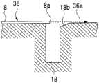
图6(a)是剖视图,(b)是(a)的局部放大剖视图。Fig. 6(a) is a sectional view, and (b) is a partially enlarged sectional view of (a).
图7是用于说明第1实施方式的打印机的工作的图。FIG. 7 is a diagram for explaining the operation of the printer of the first embodiment.
图8是表示收置凹部的变形例的局部放大剖视图。Fig. 8 is a partially enlarged cross-sectional view showing a modified example of a storage recess.
图9是表示第2实施方式的打印机的收置凹部的概略结构的立体图。9 is a perspective view showing a schematic configuration of a storage recess of a printer according to a second embodiment.
图10是表示第2实施方式的打印机的收置凹部的变形例的立体图。10 is a perspective view showing a modified example of the storage recess of the printer according to the second embodiment.
图11(a)是表示第3实施方式的打印机的主要部分结构的剖视图,(b)、(c)是表示变形例的剖视图。11( a ) is a cross-sectional view showing the configuration of main parts of the printer according to the third embodiment, and ( b ) and ( c ) are cross-sectional views showing modified examples.
图12是表示第4实施方式的打印机的主要部分结构的剖视图。Fig. 12 is a cross-sectional view showing the configuration of main parts of a printer according to a fourth embodiment.
符号说明Symbol Description
1…打印机(流体喷射装置),8…记录纸(介质),7、37…台板(介质支持部),12…流体吸收部件,13…移动机构,14…移动机构,18…收置凹部(凹部),21…记录头(流体喷射头),24…喷嘴,26…墨吸收体,40…吸引机构。1...Printer (fluid ejection device), 8...Recording paper (medium), 7, 37...Platen (media support unit), 12...Fluid absorbing member, 13...Moving mechanism, 14...Moving mechanism, 18...Accommodating recess (recess), 21...recording head (fluid ejection head), 24...nozzle, 26...ink absorber, 40...suction mechanism.
具体实施方式Detailed ways
以下,关于本发明的实施方式,参照附图进行说明。另外,在以下的说明所使用的各附图中,为了使各部件成为可以辨识的大小,适宜改变了各部件的比例尺。Hereinafter, embodiments of the present invention will be described with reference to the drawings. In addition, in each drawing used in the following description, the scale of each member is appropriately changed in order to make each member a recognizable size.
此外,在以下的说明中,关于作为本发明的流体喷射装置的一例的喷墨打印机(以下简称为打印机)进行说明。In addition, in the following description, an inkjet printer (hereinafter simply referred to as a printer) as an example of the fluid ejecting device of the present invention will be described.
(第1实施方式)(first embodiment)
图1是表示作为本发明的流体喷射装置的第1实施方式的打印机的概略结构的立体图。FIG. 1 is a perspective view showing a schematic configuration of a printer as a first embodiment of a fluid ejecting device according to the present invention.
如图1所示,本实施方式的打印机(流体喷射装置)1具备头单元2、输送记录纸(介质)8的输送装置3、供给记录纸8的供给单元4、排出通过头单元2进行了印刷的记录纸的排纸单元5和对头单元2进行维护处理的维护装置10。As shown in FIG. 1 , a printer (fluid ejection device) 1 according to the present embodiment includes a head unit 2 , a conveyance device 3 for conveying recording paper (medium) 8 , a supply unit 4 for supplying
输送装置3具备对于记录纸8从其底面侧进行支持的台板(介质支持部)7和将台板7上的记录纸8向排纸单元5输送的输送滚轴31。The transport device 3 includes a platen (medium support unit) 7 that supports the
台板7支持所输送的记录纸8,并且在与构成头单元2的多个记录头(流体喷射头)21的喷嘴面23(参照图2)之间规定预定的距离(以下称为台板间隙),配置在与头单元2相对的位置。The
输送滚轴31是具备驱动滚轴32和与之相对的从动滚轴33的夹紧滚轴,驱动滚轴32侧连接于未图示的驱动电动机,通过该驱动电动机进行旋转驱动。The conveying roller 31 is a pinch roller including a driving roller 32 and a driven roller 33 facing it. The driving roller 32 side is connected to a driving motor (not shown), and is rotationally driven by the driving motor.
排纸单元5具备排纸用滚轴51和保持通过排纸用滚轴51输送的记录处理后的记录纸8的排纸托盘52。The paper discharge unit 5 includes a paper discharge roller 51 and a paper discharge tray 52 holding the recorded
头单元2具有多个记录头21(流体喷射头)和支持这多个记录头21的安装板22。The head unit 2 has a plurality of recording heads 21 (fluid ejection heads) and a mounting
多个记录头21,遍及头单元2的有效印刷宽度而排列,并且不在一条直线上、而以作为整体成为交错状的方式排列。也就是说,相邻的记录头21彼此在与记录纸8的输送方向交差的方向上各偏离预定间距而排列。在本实施方式中,虽然在记录纸8的输送方向相邻的2个记录头组M、N(图2)都由3个记录头21构成,但是记录头21的数量并不限于此。The plurality of recording heads 21 are arranged over the effective printing width of the head unit 2 , and are arranged not in a straight line but in a zigzag shape as a whole. That is, the adjacent recording heads 21 are arranged with a predetermined pitch deviated from each other in a direction intersecting with the conveying direction of the
维护装置10构成为具有对头单元2进行吸引处理的盖单元6和用于进行冲洗工作的冲洗单元11。The maintenance device 10 is configured to include a cap unit 6 for suctioning the head unit 2 and a
盖单元6进行对上述头单元2的封盖和/或吸引工作等维护处理,其具备4个与上述4个记录头21对应的盖部件61。该盖单元6进行对上述头单元2的封盖和/或吸引工作等维护处理,具备与记录头21对应的盖部件61。该盖单元6配置在从头单元2的记录区域离开的位置。The cap unit 6 performs maintenance such as capping and/or suction work on the head unit 2 , and includes four cap members 61 corresponding to the four recording heads 21 described above. The cap unit 6 performs maintenance such as capping and/or suction work on the head unit 2 , and includes a cap member 61 corresponding to the
盖部件61构成为可以与记录头21的喷嘴面23(图2)接触。该盖部件61通过相对于记录头21的喷嘴面23分别紧密附着,可以良好地实现封盖,并且在吸引工作中能够良好地进行使墨从喷嘴面23排出的吸引工作。The cap member 61 is configured to be able to contact the nozzle surface 23 ( FIG. 2 ) of the
此外,盖单元6具有在擦拭记录头21的喷嘴面23的擦拭处理时使用的擦拭部件63。In addition, the cap unit 6 has a wiping member 63 used in a wiping process of wiping the
本实施方式的头单元2通过上述未图示的滑架可以在记录位置与维护位置之间移动。在此,所谓记录位置,是与输送装置3相对且对记录纸实施记录的位置。另一方面,所谓维护位置,是从输送装置3上退避开的位置,是与维护装置10所具备的盖单元6相对的位置。在该维护位置,实施对于头单元2的维护处理(吸引处理、擦拭处理)。The head unit 2 of the present embodiment can move between the recording position and the maintenance position by the above-mentioned unillustrated carriage. Here, the recording position is a position facing the transport device 3 and performing recording on the recording paper. On the other hand, the maintenance position is a position retracted from the conveying device 3 and is a position facing the cover unit 6 included in the maintenance device 10 . At this maintenance position, maintenance processing (suction processing, wiping processing) on the head unit 2 is carried out.
并且,头单元2在记录位置,被配置为各记录头21的各喷嘴列L(图2)相对于通过输送装置3所输送的记录纸8的输送方向上游端8a成为平行。In addition, the head unit 2 is arranged such that the nozzle rows L ( FIG. 2 ) of the recording heads 21 are parallel to the
图2是表示头单元2的底面侧的立体图。如该图所示,各记录头21按各色具备排出墨的多个喷嘴24。在此,排出同一种(例如黑色Bk、品红色M、黄色Y、蓝绿色C)墨的喷嘴24排列多个,构成1个喷嘴列L。FIG. 2 is a perspective view showing the bottom surface side of the head unit 2 . As shown in the figure, each
更详细地,记录头21具有4列与4色(黄色(Y)、品红色(M)、蓝绿色(C)、黑色(Bk))对应的喷嘴列(L(Y)、L(M)、L(C)、L(Bk))。在各喷嘴列(L(Y)、L(M)、L(C)、L(Bk))中,构成该喷嘴列(L(Y)、L(M)、L(C)、L(Bk))的喷嘴24,在与记录纸8的输送方向交差的方向上排列多个,更优选地在与记录纸8的输送方向正交的水平方向上排列。More specifically, the
此外,这些记录头21分别配置在形成于安装板22的各开口部25内。具体地,通过将各记录头21分别例如螺纹止动在安装板22的背面22b侧,喷嘴面23成为经由上述开口部25从安装板22的表面22a侧突出的状态。In addition, these recording heads 21 are disposed in respective openings 25 formed in the mounting
图3是从下方仰视头单元2和冲洗单元11的立体图。此外,图4是从记录纸的输送方向看头单元2和冲洗单元11的示意图。FIG. 3 is a perspective view of the head unit 2 and the
冲洗单元11如图3以及图4所示,具备吸收在冲洗工作时排出的墨的线状的流体吸收部件12和支持流体吸收部件12的支持机构9。As shown in FIGS. 3 and 4 , the
流体吸收部12是吸收从各喷嘴24排出的墨的线状的吸收部件,其设置为遍及头单元2的有效印刷宽度而延伸,并且沿着在与记录纸8的输送方向交叉的方向配置的多个记录头21彼此的喷嘴列L。该流体吸收部件12位于各记录头21的喷嘴面23与台板7上的记录纸8的输送区域之间。The
作为流体吸收部件12,能够使用由绢、棉、聚脂等纤维或它们的复合纤维形成的物质。此外,流体吸收部件12的粗细,优选是具有下述吸收力的粗细,即该吸收力可以充分地保持通过冲洗工作而从喷嘴排出的墨。具体地,例如,设定为直径约0.1~1.0mm的范围中的线状,更优选地设定为直径0.5mm左右。但是,为了防止与记录头21及记录纸8的接触,吸收部件12的粗细,设定为其剖面最大尺寸小于等于下述尺寸:将从记录头21到记录纸8的输送区域为止的间隔距离减去因流体吸收部件12的挠曲引起的变位量而得到的尺寸。As the fluid-
此外,该流体吸收部件12,相对于喷嘴直径具有5~50倍左右的宽度。在本实施方式中,由于记录头21的喷嘴面23与台板7之间的间隙为2mm左右、喷嘴直径为约0.02mm,所以流体吸收部件12如果其直径小于等于1mm,则能够配置在各喷嘴面23与台板7之间,并且即使考虑部件的误差,也能够由吸收部件捕获所排出的墨。In addition, the
此外,流体吸收部件12的长度,优选相对于头单元2的有效印刷宽度具有充分的长度。虽然详情在后面描述,但是由于采用依次卷起流体吸收部件12的使用完毕(墨吸收完毕)的区域并当在流体吸收部件12的全部区域吸收了墨的情况下更换流体吸收部件12本身的结构,所以为了使流体吸收部件12的更换期间成为能够耐实用的时间,优选使流体吸收部件12的长度为头单元2的有效印刷宽度的数百倍左右。该流体吸收部件12以遍及与记录纸8的输送方向交差的方向而延伸的方式由支持机构9支持。In addition, the length of the
支持机构9具备移动机构13以及移动机构14。The supporting
移动机构13,在头单元2的与输送方向交叉的方向上的两侧,在安装板22的背面22b(与各记录头21的与喷嘴面23相反侧的面),具有旋转部15、16,该旋转部15、16其各自的旋转轴与记录纸8的输送方向平行。The moving
旋转部15、16是通过以预定间隔配设的一对间隔板呈线轴形状而构成的卷绕机构,其可以在间隔板间卷绕流体吸收部件12。旋转部15、16通过未图示的驱动电动机驱动,其通过各自的旋转而进行流体吸收部件12的绕出及卷起。在本实施方式中,将旋转部15用作为绕出用,将旋转部16用作为卷起用。并且,旋转部15、16分别设置为相对于支持板17可装卸。The
此外,保持于各旋转部15、16的流体吸收部件12,架设在轴部20A、20B之间,该轴部20A、20B轴支持并固定于各支持板17的表面22a侧(与各记录头21的喷嘴面23相同侧)。由于各轴部20A、20B处于相对于各支持板17的表面22a、比各记录头21的喷嘴面23更远离的方向,所以流体吸收部件12与记录头21的喷嘴面23不接触。In addition, the
并且,通过在未图示的控制装置中分别控制旋转部15、16的旋转速度,能够不使流体吸收部件12挠曲地以适度地提供了张力的状态保持流体吸收部件12。In addition, by controlling the rotational speeds of the
移动机构14构成为支持各支持板17,并且使这各支持板17可以向相对于喷嘴面23接近的方向或远离的方向移动并且可以向与记录纸的输送方向交差的方向(与喷嘴面23平行的方向)移动。该移动机构14通过使各支持板17上下移动,在记录头21与台板7之间,使流体吸收部件12在与各记录头21的喷嘴列L相对的冲洗位置(第一位置:图9中的实线部分)与相对于这各记录头21的喷嘴面23、比记录纸8的输送区域更远离的退避位置(第二位置:图9中的虚线部分)之间移动。由于各记录头21的喷嘴面23与台板7的间隙是2mm,所以若使流体吸收部件12的直径为1mm,则只要也包含部件尺寸误差和/或配置误差而使其移动1mm~1.5mm左右,就能够使流体吸收部件12从喷嘴离开。因此,流体吸收部件12的移动所花费的时间也可减少。此外,流体吸收部件12是线状部件,即使吸收了墨质量也小,移动时的动力也小,容易移动。The moving
另一方面,移动机构14,通过使各支持板17在记录纸的输送方向(与记录纸的输送方向平行的喷嘴列的排列方向)上移动,使对于各记录头21的冲洗位置变化,使流体吸收部件12在输送方向上与不同的喷嘴列L相对。On the other hand, the moving
在此,所谓冲洗位置,是流体吸收部件12在喷嘴面23与台板7之间、配置在与构成同一头组M、N的各记录头21的喷嘴列L(构成喷嘴列L的多个喷嘴24)相对的位置的状态,是在冲洗工作时能够由流体吸收部件12吸收从正上方的喷嘴列L排出的墨的位置(墨的飞行路径上的位置)。此时,流体吸收部件12与喷嘴不接触。Here, the so-called flushing position means that the
并且,流体吸收部件12配置为,在冲洗位置(即在进行冲洗工作时)、与多个记录头21的各喷嘴列L平行,该多个记录头21是向与记录纸的输送方向交差的方向、在直线上进行排列的多个记录头。此外,流体吸收部件12与喷嘴形成面23也配置为平行。在此,所谓平行,只要是能够由流体吸收部件12吸收从各喷嘴排出的墨的范围,也可以不是完全地平行的状态。In addition, the
在本实施方式中,由于对每一个排出同一色的喷嘴列组实施冲洗工作,所以需要在与各色对应的多个喷嘴列L相对的位置随时配置流体吸收部件12。因此,本实施方式的移动机构14,构成为能够使流体吸收部件12向与各记录头21的喷嘴面23平行的方向移动。即,通过使各支持板17向与记录纸的输送方向平行的方向移动,在各头组M、N之间,使流体吸收部件12依次配置在与各记录头21的各色的喷嘴列L相对的位置、即与对应于各色的多个喷嘴列L(多个喷嘴24)相对的位置。In this embodiment, since the flushing operation is performed for each nozzle row group that discharges the same color, it is necessary to always arrange the
另一方面,所谓退避位置,是相对于各记录头21的喷嘴面23、比记录纸8的输送区域更远离头单元2的各记录头21的喷嘴面23的位置,是在记录工作时与记录纸8不接触、不妨碍输送的位置。On the other hand, the retracted position is a position farther from the
在本实施方式中,成为在与头单元2相对的台板7上确保流体吸收部件12的退避位置的结构。在此,关于本实施方式的台板7的结构进行详细说明。图5是表示本实施方式的台板的概略结构的立体图。图6(a)是剖视图,图6(b)是图6(a)的局部放大剖视图。In the present embodiment, the retracted position of the
如图5以及图6(a)所示,本实施方式的台板7构成为具备在记录纸的输送方向隔开预定间隔而配置的一对保持板部35和移动板部36,该移动板部36配置为其表面36a从一对保持板部35之间露出,并且相对于固定的保持板部35可以在与记录纸的输送方向平行的方向移动。As shown in FIG. 5 and FIG. 6( a ), the
在该移动板部36上,在其表面36a形成有可以收置流体吸收部件12的收置凹部(凹部)18。收置凹部18是遍及台板7的宽度W(与记录纸的输送方向交差的方向的宽度)整体而形成的沟,该沟的深度成为比流体吸收部件12的线径(直径)大的尺寸(深度)(图6(a)、(b))。此外,收置凹部18的宽度W2(沟宽度)形成为在收置于内部的流体吸收部件12与内壁之间空出若干间隙的程度(图6(b)),沿着台板7的表面7a输送的记录纸8的输送方向上游端8a不会陷入收置凹部18内。On the moving
此外,构成为,收置凹部18的开口侧扩开至台板7的表面7a,流体吸收部件12通过设置在开口端部的倾斜面18b、18b可靠地插入到凹部内。In addition, the opening side of the
并且,移动板部36的移动通过在未图示的控制装置中被进行控制,向与记录纸的输送方向平行的方向移动,将收置凹部18配置在预定的喷嘴列L的正下方。Further, the movement of the moving
在台板7上输送的记录纸8,从一个保持板部35的表面35a通过移动板部36的表面36a而向另一个保持板部35的表面35a移动。为了缓和保持板部35与移动板部36的高低差,在保持板部35的相对端部侧分别设置有倾斜面35b,通过该倾斜面35b使记录纸8的输送变得顺畅。The
并且,所谓上述的流体吸收部件12的退避位置,是在该收置凹部18内收置有流体吸收部件12的状态,是从与喷嘴24相对的位置退避到其更下方的台板7内部的位置。即,是相对于记录头21的喷嘴面23、比记录纸8的输送区域更远离的位置。In addition, the retracted position of the above-mentioned
另外,在退避位置,流体吸收部件12不比台板7的表面7a突出,在记录时不妨碍在台板7上输送的记录纸8的移动。In addition, in the retracted position, the
接着,关于本实施方式的打印机1的工作进行说明。Next, the operation of the printer 1 of this embodiment will be described.
图7是关于本实施方式的打印机1的工作的说明图,在以下的说明中也适宜参照图4。FIG. 7 is an explanatory diagram related to the operation of the printer 1 according to the present embodiment, and FIG. 4 is also appropriately referred to in the following description.
本实施方式的打印机1,其全部的工作通过未图示的控制装置控制,在印刷工作与印刷工作之间、即通过输送位置3依次输送的记录纸8与记录纸8之间位于记录头21的正下方的情况下进行冲洗工作。In the printer 1 of this embodiment, all of its operations are controlled by a control device not shown, and between printing jobs, that is, between the
也就是说,在本实施方式的打印机1中,在冲洗工作时,通过图4所示的移动机构14在头单元2(喷嘴24)的正下方不存在记录纸8的定时,使流体吸收部件12移动到与预定的喷嘴列L相对的位置。具体地,例如在印刷工作时,若在将流体吸收部件12配置在台板7侧的退避位置(图7(a)以及图4,由虚线表示)的状态下,记录纸8与记录纸8之间的间隙到达记录头21的下方,则使各支持板17上升,首先,将流体吸收部件12配置在与喷嘴列L(Y)相对的冲洗位置(图7(a)以及图4,由实线表示)。然后,若流体吸收部件12配置在与喷嘴列L(Y)相对的冲洗位置,则控制装置通过从构成喷嘴列L(Y)的各喷嘴24排出墨而进行冲洗工作。That is to say, in the printer 1 of the present embodiment, during the flushing operation, the fluid absorbing member is moved at the timing when the
另外,控制装置,在执行冲洗工作的期间,通过驱动移动机构13而使流体吸收部件12移动,来进行流体吸收部件12的吸收了墨的部分的卷起工作。由此,从喷嘴列L排出的墨,由于始终排出到流体吸收部件12的不包含墨的新的部分,所以在流体吸收部件12内迅速地被吸收。卷起的定时和/或速度,根据墨的种类和/或排出量、流体吸收部件12的墨收容量而适宜调节,防止流体吸收部件12饱和。In addition, the control device drives the moving
接着,通过移动机构14使流体吸收部件12向沿着记录纸的输送方向的方向移动,将流体吸收部件12配置在与喷嘴列L(Y)相邻的喷嘴列L(M)所相对的位置而实施冲洗工作。此后,依次实施对于喷嘴列L(C)、喷嘴列L(Bk)的冲洗工作。Next, the
然后,如果对于全部的喷嘴列L的冲洗工作完成,则通过图4所示的移动机构14使各支持板17(即流体吸收部件12)下降,由此如图7所示,再次将流体吸收部件12配置在退避位置。Then, if the flushing work for all the nozzle rows L is completed, each support plate 17 (that is, the fluid absorbing member 12) is lowered by the moving
另外,移动机构14,通过将一对支持板17、17配置在记录纸的输送方向上相同的位置,来使流体吸收部件12相对于喷嘴列L平行,向台板7侧下降的流体吸收部件12与台板7侧的收置凹部18成为平行。In addition, the moving
在使流体吸收部件12配置于退避位置时,控制装置使台板7的移动板部36伴随着流体吸收部件12的移动而移动。具体地,例如,在使流体吸收部件12向退避位置退避的定时,以收置凹部18存在于与流体吸收部件12相对的位置的方式,使移动板部36移动。即,使其以收置凹部18位于流体吸收部件12的正下方的方式移动。此时,冲洗对象喷嘴列L、流体吸收部件12与收置凹部18在记录纸的输送方向上一致。由此,通过使流体吸收部件12从与最后进行的冲洗实施对象喷嘴列L相对的位置向垂直方向下降,来将其配置在移动板部36的收置凹部18内的退避位置。When disposing the
若将吸收了墨的流体吸收部件12配置在退避位置,则被流体吸收部件12吸收的墨因表面张力而向收置凹部18内移动。由于收置凹部18的深度比流体吸收部件12的线径深,所以通过某一程度上使流体吸收部件12内的墨向收置凹部18内移动,可以使流体吸收部件12的墨收容量增加。When the
此外,为了防止在收置凹部18内附着的墨的粘着、堆积,在非印刷时等,空置输送流体吸收部件12而使用未吸收墨的未使用部分(墨吸收能力高的部分),适宜实施对于收置凹部18的清洁。In addition, in order to prevent the adhesion and accumulation of ink adhering to the storage
在以上那样的本实施方式的打印机1中,具备:记录头21,其具有包括喷射墨的多个喷嘴24的喷嘴列L;线状的流体吸收部件12,其沿着喷嘴列L延伸并且可以从冲洗位置移动到退避位置;台板7,其在与记录头21相对的位置支持通过记录头21实施记录处理的记录纸,并且还具备移动机构14,其使流体吸收部件12移动到冲洗位置和退避位置,冲洗位置与记录头21的各喷嘴列L(喷嘴24)相对,该记录头21在与记录纸的输送方向交差的方向上排列,退避位置相对于记录头21的喷嘴面23比记录纸的输送区域更远离。The printer 1 of the present embodiment as described above is provided with: the recording
在本实施方式中,在使线状的流体吸收部件12在记录头2与台板7之间与喷嘴24相对的冲洗位置,从喷嘴24对流体吸收部件12喷射墨。由于流体吸收部件12在相对于记录头2比记录纸8更近的位置或相同程度的位置吸收墨,所以可以不会使墨雾化地对其进行吸收。In the present embodiment, ink is ejected from the
此外,在本实施方式中,由于冲洗位置与退避位置在记录纸的输送方向一致,所以仅使配置在与喷嘴列L相对的位置的流体吸收部件12直接向下方移动,便能够将其向退避位置配置。因此,能够将冲洗位置与退避位置之间的流体吸收部件12的扫描距离仅设定为1mm~1.5mm左右。这样,由于通过使流体吸收部件12的扫描距离最短化而将其移动量抑制到最小限度,能够缩短流体吸收部件12的扫描时间,所以在连续印刷时等在输送的记录纸8彼此的纸间实施冲洗工作时,能够使纸间距离变小而可以实现高速的印刷。In addition, in the present embodiment, since the flushing position and the retracted position coincide with each other in the conveyance direction of the recording paper, it is possible to retract the
此外,由于线状的流体吸收部件12的质量也小,流体吸收部件12从退避位置向与喷嘴列L相对的冲洗位置的移动变得容易,能够以稍微的移动距离使流体吸收部件12移动到退避位置,所以能够高速化,可以以短时间结束冲洗工作。In addition, since the mass of the linear
此外,以往,由于通过具有与记录头大致相同大小的盖收容通过冲洗工作而喷射的墨,所以配置位置的确保困难,但是由于线状的流体吸收部件12,只要是直线状的间隙便可以配置,所以配置位置的自由度增加。In addition, conventionally, since the ink ejected by the flushing operation is stored in a cap having approximately the same size as the recording head, it is difficult to ensure the arrangement position. However, the linear
进而,能够将流体吸收部件12配置在与喷嘴列L相对的位置,其结果,由于喷嘴24与流体吸收部件12的距离变小,所以从喷嘴24排出的墨不会雾化地被吸收而冲洗处理性能得到提高。Furthermore, the
另外,由于头单元2与输送的记录纸的种类相应地向上下方向移动,所以记录头21的喷嘴面23与台板7之间的台板间隙变化。例如,在对厚纸和/或板等进行印刷的情况下,台板间隙变大,但是即使在这样的情况下,通过使流体吸收部件12与头单元2的移动相应地上升而配置在与喷嘴列L相对的位置,所排出的墨也不会雾化。Also, since the head unit 2 moves up and down according to the type of recording paper to be transported, the platen gap between the
此外,由于在退避位置,线状的流体吸收部件12配置于在于台板7的移动板部36设置的收置凹部18内,所以位于比记录纸8的输送区域靠下方。由此,能够防止在记录纸的输送中与流体吸收部件接触,即使在高速的送纸中也能够防止在印刷工作中塞纸等。In addition, in the withdrawn position, the linear
此外,由于流体吸收部件12是线状,所以收置凹部18的大小较小。进而,由于设置于台板7的收置凹部18比流体吸收部件12的线径深,所以能够使在冲洗工作时被流体吸收部件12吸收的墨因其表面张力而向收置凹部18内移动,使流体吸收部件12的收容量(墨吸收量)增加。由此,能够降低在连续印刷中卷绕流体吸收部件12而清洁收置凹部18内等的频率。In addition, since the
进而,也能够降低在卷绕墨吸收完毕的流体吸收部件12时墨附着到记录纸的背面的危险。此外,在需要相同的收容量的情况下,与仅使流体吸收部件12收容的情况比较,使墨收容到收置凹部18内的情况,能够使流体吸收部件12的线径变细。由此,通过使流体吸收部件12的质量变小,更高速的扫描成为课题,实现印刷的高速化。Furthermore, it is also possible to reduce the risk of ink adhering to the back surface of the recording paper when the ink-absorbed
此外,使附着在收置凹部18内的墨处于流体吸收部件12的未使用部分(未吸收墨的部分)等墨吸收能力高的状态的部分,通过在非印刷时等空置输送流体吸收部件12而实施收置凹部18内的清洁,能够防止墨粘着、堆积在收置凹部18内,能够实施稳定的冲洗处理。In addition, the ink adhering to the
此外,通过在流体吸收部件12的未使用部分实施收置凹部18内整体的清洁,不必担心由于残留墨而污染记录纸8的背面。Furthermore, by cleaning the entire interior of the
另外,收置凹部18的宽度W2(沟宽度),通过形成为在插入到内部的流体吸收部件12与内壁之间空出若干间隙的程度,以由细的纤维织成的线的毛细管力,附着在收置凹部18的内壁面的墨能够被流体吸收部件12吸收而使收置凹部18内清洁化。In addition, the width W2 (groove width) of the
此外,在本实施方式中,通过由控制装置分别控制旋转部15、16的旋转,保持提供了流体吸收部件12的张力的状态不变,通过利用移动机构14使各支持板17上下移动,使流体吸收部件12配置在冲洗位置和退避位置,但是也可以在配置于退避位置时,通过不提供流体吸收部件12的张力、使其挠曲,使吸收部件12下降、配置于退避位置。由于通过卷绕流体吸收部件12而使其上升,所以不需要复杂的线扫描机构。在该情况,通过对流体吸收部件12设置重量,可更高精度地进行线操作。In addition, in this embodiment, by controlling the rotations of the
此外,线状的流体吸收部件12存在着容易振动的问题,有可能流体吸收部件由于振动而从可以承接墨的区域向离开而污染记录纸等。但是,在本实施方式中,由于可以退避到收置凹部18内,所以可靠地防止退避位置的流体吸收部件12的振动。由此,例如,能够防止由于吸收了墨的流体吸收部件12振动而污染记录纸8的不良状况。In addition, the linear
另外,在本实施方式中,虽然在收置凹部18的开口端部的两侧(在记录纸的输送方向上相对的两端部)设置了倾斜面18b、18b,但是不需要一定设置在两侧,而如图8所示,优选至少在位于记录纸8的输送方向下游侧的端部侧设置倾斜面18b。由此,所输送的记录纸8的输送方向上游端8a难以陷入收置凹部18内,而经由倾斜面18b再次引导到移动板部36的表面36a。这样,仅在收置凹部18的单侧设置倾斜面18b的结构这一方,在收置凹部18上防止记录纸8的端部的陷入的效果提高。In addition, in this embodiment, although the
在此,在本实施方式中,为了使支持记录纸的台板7和头单元2的间隙与记录纸8的种类相应地变化,构成为头单元2通过在上下方向移动而可以相对于台板7进退。由此,在本实施方式中,在冲洗工作时,也可以设定为能够与记录纸8的种类相应地适宜选择是否使流体吸收部件12向第一位置移动。Here, in this embodiment, in order to change the gap between the
这样,通过形成为与记录纸8的种类相应地使台板间隙变化的结构,在记录纸8的厚度薄的情况下,台板间隙变小。即,如果台板间隙变小,则由于必然喷嘴24与流体吸收部件12接近,所以即使在冲洗工作时不使流体吸收部件12向与喷嘴24相对的位置移动来实施冲洗工作,从喷嘴24排出的墨也能够在雾化之前在流体吸收部件12中吸收。In this way, the platen gap is changed in accordance with the type of
另一方面,在对于有一定厚度的记录纸在记录中实施冲洗工作的情况下,由于台板间隙变大,所以使流体吸收部件12上升而配置在与喷嘴24相对的位置,通过与各喷嘴24相对而进行上述的良好的冲洗工作。On the other hand, when flushing is performed during recording on recording paper with a certain thickness, since the platen gap becomes large, the
这样,在冲洗工作时,与记录纸的种类相应地将流体吸收部件配置在与喷嘴24相对的位置或退避位置。即,通过与记录纸8的种类相应地选择是否使流体吸收部件12向与喷嘴24相对的位置移动,驱动变得容易并且可以实现省功率化。此外,由于可以不使流体吸收部件12向与喷嘴24相对的位置移动而在退避位置进行冲洗工作,所以可实现处理时间的缩短,提高印刷速度。In this way, during the flushing operation, the fluid absorbing member is arranged at a position facing the
接着,关于本发明的其他实施方式进行描述。Next, other embodiments of the present invention will be described.
虽然以下所示的各实施方式的打印机的基本结构与上述第1实施方式大致相同,但是在台板的结构中不同。因此,在以下的说明中,关于台板详细说明,省略相同的部分的说明。此外,在说明所使用的附图中,对与图1~图7相同的构成要素赋予相同的符号。The basic configurations of the printers of the embodiments described below are substantially the same as those of the first embodiment described above, but differ in the configuration of the platen. Therefore, in the following description, the platen will be described in detail, and the description of the same parts will be omitted. In addition, in the drawings used for description, the same code|symbol is attached|subjected to the same component as FIG. 1-FIG.
(第2实施方式)(second embodiment)
接着,关于本发明的第2实施方式的台板,使用图9进行说明。图9是表示第2实施方式的台板的主要部分结构的剖视图。Next, a platen according to a second embodiment of the present invention will be described using FIG. 9 . Fig. 9 is a cross-sectional view showing the configuration of main parts of the tabletop according to the second embodiment.
如图9所示,在本实施方式的打印机的台板9中,在收置凹部18内设置有吸收墨的一对墨吸收体26。这些墨吸收体26,遍及收置凹部18的延伸方向整体而沿着收置凹部18的内壁面分别配置,在墨吸收体26、26彼此之间,设置有插入流体吸收部件12的间隙27。该间隙27设定得比流体吸收部件12的线径小,由此在所收置的流体吸收部件12的圆周侧面接触各墨吸收体26的面积变大,能够从流体吸收部件12吸收更多的墨。作为墨吸收体26,举出海绵部件或多孔质部件。As shown in FIG. 9 , in the
通过这样的结构,能够使流体吸收部件12内的墨更快速地移动到墨吸收体26,可以使流体吸收部件12的墨收容量恢复到接近于初始状态的状态。由此,可以降低在连续印刷中卷绕流体吸收部件12而清洁收置凹部18内等的频率,能够使流体吸收部件12的更换期间成为长期间。另外,也可以适宜更换该墨吸收体26。With such a configuration, the ink in the
在将墨吸收体26间的间隙设定为通过配置在收置凹部18内的流体吸收部件12而压缩各墨吸收体26的一部分那样的尺寸的情况下,能够清洁墨吸收体26而保持洁净。When the gap between the
另一方面,如图10所示,在将墨吸收体26的间隙设定得与流体吸收部件12的线径大致相等或比其稍微小的情况下,不会通过流体吸收部件12而部分地压缩墨吸收体26。因此,流体吸收部件12仅与各墨吸收体26接触,容易吸引墨,墨吸收体26的墨收容量也稍微增加。On the other hand, as shown in FIG. 10 , when the gap of the
(第3实施方式)(third embodiment)
接着,关于本发明的第3实施方式的打印机,使用图11进行说明。图11(a)是表示第3实施方式的台板的主要部分结构的剖视图。此外,图11(b)、图11(c)是表示第3实施方式的变形例的剖视图。Next, a printer according to a third embodiment of the present invention will be described using FIG. 11 . Fig. 11(a) is a cross-sectional view showing the configuration of main parts of the tabletop of the third embodiment. 11( b ) and FIG. 11( c ) are cross-sectional views showing modifications of the third embodiment.
如图11(a)所示,在本实施方式的打印机的台板上,设置有回收收置凹部18内的墨的墨吸引机构40。墨吸引机构40包括墨积存部41、吸引流路42和吸引泵43。墨积存部41呈具有在内部可以暂时贮存墨的空间的有底箱状。并且,设置在构成台板7的移动板部36的背面36c侧,经由设置在收置凹部18的一端侧的底部的未图示的开口部,收置凹部18内与上述空间连通。As shown in FIG. 11( a ), on the platen of the printer according to this embodiment, an
在墨积存部41的底部中央,以贯通该底部的方式设置有吸引口44。并且,在该吸引口44上连接着吸引流路42,在该吸引流路42上连接着吸引泵43。At the center of the bottom of the
这样的结构的打印机,通过吸引泵43的作用,能够吸引收置凹部18内的墨而使其排出。这样,通过吸引泵43使存在于收置凹部18内的墨强制地排出,由此使收置凹部18的墨收容量增加,进而关联到流体吸收部件12的墨收容量的增加。In the printer having such a configuration, the ink in the
此外,通过设置墨积存部41,可以使收置凹部18内的墨暂时地积存,能够防止从收置凹部18内溢出墨。此外,也可以缩短吸收泵43的工作频率以及驱动时间。In addition, by providing the
另外,如图11(b)所示,当在收置凹部18内配置有墨吸收体26的情况下,优选对墨吸收体26的墨积存部41侧的端部进行研碎等而压缩。通过这样使墨吸收体26内的气孔变小,通过毛细管力容易使墨向压缩了的端部侧移动。因此,能够对存在于与墨吸引机构40侧相反侧的收置凹部18内的墨不会残留地进行吸引,关联到冲洗性能的稳定化。In addition, as shown in FIG. 11( b ), when the
此外,如图11(c)所示,也可以在收置凹部18的底部具有倾斜。即,通过以朝向墨积存部41侧逐渐变低的方式倾斜,在收置凹部18内收容的墨向墨积存部41侧自动移动。由此,能够防止墨残留在吸引泵43的吸引作用难以到达的收置凹部18的另一端部侧。Moreover, as shown in FIG.11(c), the bottom part of the accommodation recessed
(第4实施方式)(fourth embodiment)
接着,关于本实施方式的打印机,使用图12进行说明。图12是表示第4实施方式的台板的主要部分结构的剖视图。Next, the printer according to this embodiment will be described using FIG. 12 . Fig. 12 is a cross-sectional view showing the configuration of main parts of a tabletop according to a fourth embodiment.
如图12所示,本实施方式的打印机的台板37,不由多个板部件构成,而由一块板状部件形成,在其表面(记录纸支持面)侧设置有多个收置凹部18。这些收置凹部18在输送方向各具有2组、总计8个的收置凹部18,以便使对应于头单元2的各色的喷嘴列L(Y)、L(M)、L(C)、L(Bk)的4个收置凹部18与各头组M、N对应。As shown in FIG. 12 , the
由于各收置凹部18位于各喷嘴列L的正下方,所以不需要伴随着流体吸收部件12向记录纸的输送方向的移动而使台板移动。由此,由于仅通过组装时的位置对准,便可确定各记录头的喷嘴列L与台板的收置凹部18的位置,所以不需要在工作时台板37相对于流体吸收部件12的高度的位置对准。由此,可以提高各自的定位精度,对于在使针对各色的喷嘴列L的各个冲洗位置配置的流体吸收部件12,仅通过使其直接下降,便可以可靠地使其向预定的收置凹部18内的退避位置移动。Since each
另外,在本实施方式中,虽然使用了1条流体吸收部件12,但是也可以使用与各色的喷嘴列L对应的共计8条流体吸收部件12。在该情况下,可以对于在头单元2中设置的全部记录头21的各喷嘴列L(喷嘴24)同时实施冲洗工作,实现处理时间的缩短。In addition, in the present embodiment, one
这多个流体吸收部件12分别可以退避到设置于台板侧的各收置凹部18内。Each of the plurality of
此外,在本实施方式中,在印刷中,通过在退避位置配置的多个流体吸收部件12吸收从各记录头21的各喷嘴24排出的墨,由此也可以应对无边界印刷。In addition, in this embodiment, during printing, ink discharged from each
以上,参照附图对本发明的优选的实施方式进行了说明,但是本发明当然并不限于这样的例子,而也可以使上述各实施方式相组合。显然只要是本领域技术人员,就能够在权利要求所记载的技术思想的范围内想到各种变形例或修改例,并且关于这些变形例或修改例也理解为是属于本发明的技术范围内的方案。As above, preferred embodiments of the present invention have been described with reference to the drawings, but the present invention is of course not limited to such examples, and the above-described embodiments may be combined. It is obvious that those skilled in the art can think of various modifications or modifications within the scope of the technical ideas described in the claims, and it is also understood that these modifications or modifications belong to the technical scope of the present invention. plan.
例如,在上述实施方式中,对于在与记录纸的输送方向交差的方向排列的多个喷嘴列L使1条流体吸收部件12相对应,但是本发明并不限定于此,而也可以对于在记录纸的输送方向相邻的一对喷嘴列L使1条流体吸收部件12相对应。For example, in the above-mentioned embodiment, one
此外,在冲洗工作中,可以对于在头单元2中设置的多个记录头21的全部的喷嘴列L实施处理,但是也可以仅对于特定的喷嘴列L实施冲洗工作。In addition, in the flushing operation, processing may be performed on all the nozzle rows L of the plurality of recording heads 21 provided in the head unit 2 , but the flushing operation may be performed on only a specific nozzle row L.
此外,在上述实施方式中,关于遍及有效印刷宽度而排列有多个头的结构进行了说明。但是,本发明并不限定于此,而也可以形成为具备单个行式头作为记录头的结构。In addition, in the above-mentioned embodiment, the description has been given about the configuration in which a plurality of heads are arranged over the effective printing width. However, the present invention is not limited thereto, and may be configured to include a single line head as a recording head.
此外,在上述实施方式中,关于将本发明应用于行式头方式的打印机的结构进行了说明。但是,本发明并不限于此,而也能够应用于串行方式的打印机。In addition, in the above-mentioned embodiments, the configuration in which the present invention is applied to a line head type printer has been described. However, the present invention is not limited to this, but can also be applied to serial printers.
此外,在上述实施方式中,采用了通过移动流体吸收部件12而使流体吸收部件12与记录头21的位置关系变化的结构。但是,本发明并不限于此,而也可以采用通过移动记录头21而使吸收部件12与记录头21的位置关系变化的结构。In addition, in the above-described embodiment, a configuration is adopted in which the positional relationship between the
在上述实施方式中,采用了喷墨式的打印机,但是也可以采用喷射、排出墨以外的其他流体的流体喷射装置和收置该流体的流体容器。也可以应用于具备排出微小量的液滴的流体喷射头等的各种流体喷射装置。另外,所谓液滴,指从上述流体喷射装置排出的流体的状态,也包含以粒状、泪状、线状拖尾的状态。此外,在此所谓流体,只要是能够使流体喷射装置进行喷射那样的材料即可。In the above-described embodiments, an inkjet printer is used, but a fluid ejection device that ejects and discharges fluid other than ink and a fluid container that stores the fluid may also be used. It can also be applied to various fluid ejection devices including a fluid ejection head that ejects a minute amount of liquid droplets. In addition, the term "droplet" refers to the state of the fluid discharged from the above-mentioned fluid ejection device, and also includes the state of trailing in a granular shape, a tear shape, or a linear shape. In addition, the term "fluid" here may be any material as long as it can be ejected by a fluid ejection device.
例如,物质只要是液相时的状态的物质即可,包含:粘性高或低的液体状态,溶胶、凝胶水、其他的无机溶剂、有机溶剂、溶液、液状树脂、液状金属(金属溶液)这样的流体状态,此外不仅是作为物质的一种状态的流体,而且还将包含颜料和/或金属微粒等固体物质的功能材料的微粒溶解、分散或混合在溶剂中而成的物质等。此外,作为流体的代表性例子,举出在上述实施例的方式中所说明的那样的墨和/或液晶等。在此,所谓墨,包含一般的水性墨和油性墨以及凝胶墨、热熔性墨等各种流体组成物。For example, as long as the substance is in the state of liquid phase, it includes: liquid state with high or low viscosity, sol, gel water, other inorganic solvents, organic solvents, solution, liquid resin, liquid metal (metal solution) Such a fluid state is not only a fluid as a state of matter, but also a substance obtained by dissolving, dispersing or mixing particles of functional materials including solid substances such as pigments and/or metal particles in a solvent. Moreover, the ink and/or liquid crystal etc. which were demonstrated in the form of the said Example are mentioned as a representative example of a fluid. Here, the ink includes general water-based inks, oil-based inks, gel inks, hot-melt inks, and other fluid compositions.
作为流体喷射装置的具体例子,例如也可以是喷射以分散或溶解的形式包含在液晶显示器、EL(电致发光)显示器及表面发光显示器、滤色器的制造等中使用的电极材料、色材等材料的流体的流体喷射装置、喷射在生物芯片制造中使用的生物有机物的流体喷射装置、用作为精密移液管而喷射成为试料的流体的流体喷射装置、印染装置和/或微喷注器等。As a specific example of a fluid ejection device, for example, it is also possible to eject electrode materials and color materials used in the manufacture of liquid crystal displays, EL (electroluminescence) displays, surface emission displays, and color filters in a dispersed or dissolved form. A fluid ejection device for fluids such as materials, a fluid ejection device for ejecting bioorganic substances used in the manufacture of biochips, a fluid ejection device for ejecting a fluid as a sample as a precision pipette, a printing and dyeing device and/or a micro-injection device device etc.
进而,也可以采用在钟表、照相机等精密机械上以针点方式喷射润滑油的流体喷射装置、为了形成在光通信元件等中使用的微小半球透镜(光学透镜)等而将紫外线固化树脂等透明树脂液喷射在基板上的流体喷射装置、为了对基板等进行蚀刻而喷射酸或碱等蚀刻液的流体喷射装置。而且,能够将本发明应用于它们之中的任何一种喷射装置及流体容器。Furthermore, it is also possible to use a fluid injection device that sprays lubricating oil in a pinpoint manner on precision machines such as clocks and cameras, and to make ultraviolet curable resins, etc. A fluid ejection device that ejects a resin liquid onto a substrate, and a fluid ejection device that ejects an etchant such as acid or alkali to etch a substrate. Also, the present invention can be applied to any of these spraying devices and fluid containers.
Claims (9)
Translated fromChineseApplications Claiming Priority (2)
| Application Number | Priority Date | Filing Date | Title |
|---|---|---|---|
| JP2009248932AJP2011093193A (en) | 2009-10-29 | 2009-10-29 | Fluid jetting apparatus and maintenance method |
| JP248932/2009 | 2009-10-29 |
Publications (2)
| Publication Number | Publication Date |
|---|---|
| CN102139569A CN102139569A (en) | 2011-08-03 |
| CN102139569Btrue CN102139569B (en) | 2013-11-27 |
Family
ID=43924974
Family Applications (1)
| Application Number | Title | Priority Date | Filing Date |
|---|---|---|---|
| CN2010105339979AExpired - Fee RelatedCN102139569B (en) | 2009-10-29 | 2010-10-29 | Fluid ejection device and method of maintenance |
Country Status (3)
| Country | Link |
|---|---|
| US (1) | US8360550B2 (en) |
| JP (1) | JP2011093193A (en) |
| CN (1) | CN102139569B (en) |
Families Citing this family (8)
| Publication number | Priority date | Publication date | Assignee | Title |
|---|---|---|---|---|
| JP6078438B2 (en)* | 2013-08-30 | 2017-02-08 | 株式会社Kelk | Thermoelectric generator module |
| JP6819057B2 (en)* | 2016-03-18 | 2021-01-27 | セイコーエプソン株式会社 | Recording device |
| JP6776568B2 (en)* | 2016-03-18 | 2020-10-28 | セイコーエプソン株式会社 | Recording device |
| JP2020032537A (en)* | 2018-08-27 | 2020-03-05 | セイコーエプソン株式会社 | Inkjet recording device |
| JP7380057B2 (en)* | 2019-10-11 | 2023-11-15 | 京セラドキュメントソリューションズ株式会社 | inkjet recording device |
| JP7427913B2 (en)* | 2019-10-30 | 2024-02-06 | セイコーエプソン株式会社 | Liquid injection system, maintenance method of liquid injection system |
| US11860180B2 (en)* | 2020-02-10 | 2024-01-02 | Funai Electric Co., Ltd. | Removable maintenance fluid holder |
| JP7667954B2 (en)* | 2020-07-31 | 2025-04-24 | 株式会社リコー | LIQUID EJECTION APPARATUS, LIQUID EJECTION UNIT, AND DRIVE METHOD FOR LIQUID EJECTION HEAD IN LIQUID EJECTION APPARATUS |
Citations (4)
| Publication number | Priority date | Publication date | Assignee | Title |
|---|---|---|---|---|
| US5847674A (en)* | 1996-05-02 | 1998-12-08 | Moore Business Forms, Inc. | Apparatus and methods for maintaining optimum print quality in an ink jet printer after periods of inactivity |
| CN1778559A (en)* | 2004-11-27 | 2006-05-31 | 三星电子株式会社 | Inkjet Printers |
| CN1836904A (en)* | 2005-03-24 | 2006-09-27 | 兄弟工业株式会社 | Inkjet recording equipment |
| CN1923520A (en)* | 2005-09-02 | 2007-03-07 | 精工爱普生株式会社 | liquid injection device |
Family Cites Families (5)
| Publication number | Priority date | Publication date | Assignee | Title |
|---|---|---|---|---|
| US7562961B2 (en)* | 2003-09-22 | 2009-07-21 | Fujifilm Corporation | Droplet discharging apparatus, image forming apparatus and preliminary discharge method |
| JP2006264169A (en)* | 2005-03-24 | 2006-10-05 | Fuji Photo Film Co Ltd | Image forming apparatus |
| JP2008238562A (en) | 2007-03-27 | 2008-10-09 | Seiko Epson Corp | Fluid ejection apparatus and control method thereof |
| JP5272318B2 (en) | 2007-03-27 | 2013-08-28 | セイコーエプソン株式会社 | Fluid ejection apparatus and control method thereof |
| US8888230B2 (en)* | 2008-11-13 | 2014-11-18 | Seiko Epson Corporation | Fluid ejecting apparatus |
- 2009
- 2009-10-29JPJP2009248932Apatent/JP2011093193A/enactivePending
- 2010
- 2010-10-28USUS12/914,180patent/US8360550B2/ennot_activeExpired - Fee Related
- 2010-10-29CNCN2010105339979Apatent/CN102139569B/ennot_activeExpired - Fee Related
Patent Citations (4)
| Publication number | Priority date | Publication date | Assignee | Title |
|---|---|---|---|---|
| US5847674A (en)* | 1996-05-02 | 1998-12-08 | Moore Business Forms, Inc. | Apparatus and methods for maintaining optimum print quality in an ink jet printer after periods of inactivity |
| CN1778559A (en)* | 2004-11-27 | 2006-05-31 | 三星电子株式会社 | Inkjet Printers |
| CN1836904A (en)* | 2005-03-24 | 2006-09-27 | 兄弟工业株式会社 | Inkjet recording equipment |
| CN1923520A (en)* | 2005-09-02 | 2007-03-07 | 精工爱普生株式会社 | liquid injection device |
Also Published As
| Publication number | Publication date |
|---|---|
| US8360550B2 (en) | 2013-01-29 |
| CN102139569A (en) | 2011-08-03 |
| US20110102498A1 (en) | 2011-05-05 |
| JP2011093193A (en) | 2011-05-12 |
Similar Documents
| Publication | Publication Date | Title |
|---|---|---|
| CN102139569B (en) | Fluid ejection device and method of maintenance | |
| JP6606958B2 (en) | Liquid ejecting apparatus and cleaning apparatus | |
| CN203246190U (en) | Maintenance device and liquid ejecting apparatus | |
| JP2012101476A (en) | Liquid ejection device | |
| JP2014172239A (en) | Liquid jetting device | |
| JP6142575B2 (en) | Liquid ejector | |
| JP2020189446A (en) | Liquid ejector and maintenance method for the same | |
| US6669325B2 (en) | Apparatus and method for placing fluid droplets onto an object | |
| JP5565232B2 (en) | Liquid ejector | |
| JP5668467B2 (en) | Liquid ejector | |
| JP4666946B2 (en) | Discharge port surface cleaning method, liquid discharge apparatus, and probe carrier manufacturing apparatus | |
| JP5803089B2 (en) | Fluid ejection device | |
| US6860582B2 (en) | Ink receiving apparatus and method | |
| KR100727987B1 (en) | Hybrid inkjet head and image forming apparatus having the wiping device of the inkjet head | |
| JP4321592B2 (en) | Liquid ejector | |
| JP2005246698A (en) | Liquid ejecting apparatus and flushing method for liquid ejecting apparatus | |
| JP5857748B2 (en) | Liquid ejector | |
| JP2005342991A (en) | Liquid ejecting apparatus and liquid absorbing apparatus for liquid ejecting head | |
| JP2007144838A (en) | Liquid ejector | |
| JP2012192567A (en) | Maintenance device, maintenance method and liquid ejecting apparatus | |
| JP2018030333A (en) | Liquid ejector | |
| JP6003576B2 (en) | Liquid ejection device | |
| JP2011093194A (en) | Fluid jetting apparatus and maintenance method | |
| KR20050054143A (en) | Inkjet printer | |
| JP5499883B2 (en) | Fluid ejection device |
Legal Events
| Date | Code | Title | Description |
|---|---|---|---|
| C06 | Publication | ||
| PB01 | Publication | ||
| C10 | Entry into substantive examination | ||
| SE01 | Entry into force of request for substantive examination | ||
| C14 | Grant of patent or utility model | ||
| GR01 | Patent grant | ||
| CF01 | Termination of patent right due to non-payment of annual fee | Granted publication date:20131127 | |
| CF01 | Termination of patent right due to non-payment of annual fee |