CN102137584A - Temperature gain control device and method thereof - Google Patents
Temperature gain control device and method thereofDownload PDFInfo
- Publication number
- CN102137584A CN102137584ACN2010101036021ACN201010103602ACN102137584ACN 102137584 ACN102137584 ACN 102137584ACN 2010101036021 ACN2010101036021 ACN 2010101036021ACN 201010103602 ACN201010103602 ACN 201010103602ACN 102137584 ACN102137584 ACN 102137584A
- Authority
- CN
- China
- Prior art keywords
- temperature
- gain control
- control
- operating ambient
- pwm signal
- Prior art date
- Legal status (The legal status is an assumption and is not a legal conclusion. Google has not performed a legal analysis and makes no representation as to the accuracy of the status listed.)
- Granted
Links
- 238000000034methodMethods0.000titleclaimsabstractdescription24
- 238000010438heat treatmentMethods0.000claimsdescription34
- 230000006698inductionEffects0.000claimsdescription3
- 238000005485electric heatingMethods0.000claims2
- 230000000694effectsEffects0.000abstractdescription5
- 238000010586diagramMethods0.000description8
- 230000002159abnormal effectEffects0.000description3
- 238000004364calculation methodMethods0.000description3
- 238000001816coolingMethods0.000description2
- 239000012530fluidSubstances0.000description2
- 238000013021overheatingMethods0.000description2
- 230000002411adverseEffects0.000description1
- 239000012141concentrateSubstances0.000description1
- 230000006870functionEffects0.000description1
- 239000007788liquidSubstances0.000description1
- 238000012986modificationMethods0.000description1
- 230000004048modificationEffects0.000description1
- XLYOFNOQVPJJNP-UHFFFAOYSA-NwaterSubstancesOXLYOFNOQVPJJNP-UHFFFAOYSA-N0.000description1
Images

Landscapes
- Control Of Temperature (AREA)
Abstract
Description
Translated fromChinese技术领域technical field
本发明涉及一种控制装置及其方法,特别是涉及一种利用加热器,用以对电子元件的工作环境温度进行温度控制的温度增益控制装置及其方法。The invention relates to a control device and a method thereof, in particular to a temperature gain control device and a method thereof which utilize a heater to control the temperature of the working environment of electronic components.
背景技术Background technique
近年来,随着电子设备的普及,许多电子设备已被应用于各种恶劣的温度工作环境下进行运作,然而,由于其工作环境恶劣,所以故障及异常运作的情形亦屡见不鲜。因此,如何使电子设备适应恶劣的温度工作环境,并且能够使其正常运作便成为各家厂商亟欲解决的问题之一。In recent years, with the popularization of electronic devices, many electronic devices have been used to operate in various harsh temperature working environments. However, due to the harsh working environment, failures and abnormal operations are common. Therefore, how to adapt the electronic equipment to the severe temperature working environment and make it operate normally has become one of the problems that various manufacturers want to solve urgently.
一般而言,恶劣的温度工作环境分为过热及过冷两种。其中,由于电子元件运作时本身会发热,因此若在过热的工作环境下,其电子元件的寿命将会大幅缩短,故障率也会居高不下。目前已经有许多方案能够有效解决过热的问题,例如:气冷散热、水冷散热......等等。然而在过冷的工作环境下,电子元件运作时本身的发热不足以维持所需的工作环境温度时,将使电子元件无法正常运作,举例来说,液态轴承硬碟在过低的工作环境温度时,其液态轴承中的油膜可能无法维持在液体形态,如此将造成无法发挥其特性,甚至使液态轴承硬碟损毁。Generally speaking, harsh temperature working environments are divided into two types: overheating and overcooling. Among them, since the electronic components themselves generate heat during operation, if the working environment is overheated, the service life of the electronic components will be greatly shortened, and the failure rate will remain high. At present, there are many solutions that can effectively solve the problem of overheating, such as: air cooling, water cooling, etc. However, in a super-cooled working environment, when the heat generated by the electronic components is not enough to maintain the required working environment temperature, the electronic components will not work normally. At this time, the oil film in the fluid dynamic bearing may not be able to maintain the liquid state, which will cause the failure of its characteristics, and even damage the fluid dynamic bearing hard disk.
有鉴于此,便有厂商提出以电路布局的方式,将发热元件集中在需要维持一定工作环境温度的电子元件周围,甚至额外增加加热装置对电子元件进行加热。不过,上述电路布局的方式,其提升工作环境温度有限,具有许多不确定性;而额外增加加热装置的方式则造成电子设备的成本提升,甚至电路布局上的困扰,故皆无法有效解决在工作环境温度过低时,电子元件无法正常运作的问题。In view of this, some manufacturers propose to use circuit layout to concentrate heating elements around the electronic elements that need to maintain a certain working environment temperature, and even add additional heating devices to heat the electronic elements. However, the above-mentioned method of circuit layout has a limited ability to increase the temperature of the working environment and has many uncertainties; while the method of adding an additional heating device will cause an increase in the cost of electronic equipment and even troubles in circuit layout, so it cannot effectively solve the problem during work. Electronic components cannot function properly when the ambient temperature is too low.
综上所述,可知先前技术中长期以来一直存在当工作环境温度过低时,电子元件无法正常运作的问题,因此实有必要提出改进的技术手段,来解决这一个问题。To sum up, it can be known that the prior art has long had the problem that the electronic components cannot operate normally when the working environment temperature is too low. Therefore, it is necessary to propose improved technical means to solve this problem.
发明内容Contents of the invention
有鉴于先前技术存在的问题,本发明遂揭露一种温度增益控制装置及其方法。In view of the problems existing in the prior art, the present invention discloses a temperature gain control device and a method thereof.
本发明所揭露的温度增益控制装置,应用于具有电子元件的设备中,包含:感应模块、BIOS模块、加热模块及加热器。其中,感应模块用以持续感应设备中的工作环境温度,并将此工作环境温度与预先设置的第一温度参数进行比对,且根据比对结果产生控制信号;BIOS模块用以允许设定并储存第二温度参数,并持续将所述工作环境温度偏移一个间隔数值后,将偏移后的工作环境温度与第二温度参数进行比对,且根据比对结果选择控制模式以驱动控制芯片产生相应的PWM信号;加热模块用以根据控制信号产生输出功率,且于PWM信号产生后,同时搭配控制信号及PWM信号调整输出功率;加热器设置于电子元件周围,用以接收所述输出功率,并且根据此输出功率对电子元件进行加热。The temperature gain control device disclosed in the present invention is applied to equipment with electronic components, including: a sensing module, a BIOS module, a heating module and a heater. Among them, the sensing module is used to continuously sense the working environment temperature in the device, compare the working environment temperature with the preset first temperature parameter, and generate a control signal according to the comparison result; the BIOS module is used to allow setting and storing the second temperature parameter, and continuously shifting the working environment temperature by an interval value, comparing the shifted working environment temperature with the second temperature parameter, and selecting a control mode according to the comparison result to drive the control chip Generate a corresponding PWM signal; the heating module is used to generate output power according to the control signal, and after the PWM signal is generated, adjust the output power with the control signal and the PWM signal at the same time; the heater is arranged around the electronic component to receive the output power , and the electronic components are heated according to this output power.
承上所述,其中工作环境温度与第一温度参数可通过比较器进行比对,此比较器于工作环境温度与第一温度参数相同时产生控制信号;第二控制信号可通过基本输入/输出系统(Basic Input/Output System,BIOS)所设定,且于设定后储存于挥发性内存中;控制模式包含温度范围,且每一温度范围对应有相应的PWM信号;间隔数值为使工作环境温度维持在正温度的数值;控制芯片为超级(Super)I/O芯片;加热器可分别为软板电热片。另外,感应模块至少包含温度参数储存器、温度感应器及比较器;BIOS模块至少包含内存单元、BIOS单元及控制芯片;加热模块至少包含温度控制开关、PWM控制开关及功率控制开关。As mentioned above, the working environment temperature and the first temperature parameter can be compared through a comparator, and the comparator generates a control signal when the working environment temperature is the same as the first temperature parameter; the second control signal can be passed through the basic input/output The system (Basic Input/Output System, BIOS) is set and stored in the volatile memory after setting; the control mode includes a temperature range, and each temperature range corresponds to a corresponding PWM signal; the interval value is for the working environment The temperature is maintained at a positive value; the control chip is a Super I/O chip; the heaters can be soft board electric heaters. In addition, the sensing module at least includes a temperature parameter storage, a temperature sensor, and a comparator; the BIOS module includes at least a memory unit, a BIOS unit, and a control chip; the heating module includes at least a temperature control switch, a PWM control switch, and a power control switch.
至于本发明的温度增益控制方法,应用于具有电子元件及加热器的装置中,其步骤包括:持续感应设备中的工作环境温度,并将此工作环境温度与预先设置的第一温度参数进行比对,且根据比对结果产生控制信号;允许设定并储存第二温度参数,并持续将所述工作环境温度偏移一个间隔数值后,将偏移后的工作环境温度与第二温度参数进行比对,且根据比对结果选择控制模式以驱动控制芯片产生相应的PWM信号;根据控制信号产生输出功率,且于PWM信号产生后,同时搭配控制信号及PWM信号调整输出功率;加热器设置于电子元件周围,用以接收此输出功率,并且根据此输出功率对电子元件进行加热。As for the temperature gain control method of the present invention, it is applied to devices with electronic components and heaters, and the steps include: continuously sensing the working environment temperature in the equipment, and comparing the working environment temperature with the preset first temperature parameter Yes, and a control signal is generated according to the comparison result; the second temperature parameter is allowed to be set and stored, and after continuously shifting the working environment temperature by an interval value, the shifted working environment temperature is compared with the second temperature parameter Compare, and select the control mode according to the comparison result to drive the control chip to generate the corresponding PWM signal; generate the output power according to the control signal, and after the PWM signal is generated, adjust the output power with the control signal and the PWM signal at the same time; the heater is set at Around the electronic components, it is used to receive the output power and heat the electronic components according to the output power.
本发明所揭露的装置与方法如上,与先前技术之间的差异在于本发明是通过感应工作环境温度,并且根据此工作环境温度产生控制信号及PWM信号,用以动态控制设置于电子元件周围的加热器进行加热。The device and method disclosed in the present invention are as above, and the difference between the present invention and the prior art is that the present invention senses the temperature of the working environment, and generates a control signal and a PWM signal according to the temperature of the working environment, so as to dynamically control the devices arranged around the electronic components. The heater heats up.
通过上述的技术手段,本发明可以在工作环境温度过低时,达到提高电子元件的稳定性的技术功效。Through the above-mentioned technical means, the present invention can achieve the technical effect of improving the stability of electronic components when the temperature of the working environment is too low.
附图说明Description of drawings
图1为本发明温度增益控制装置的方块图。FIG. 1 is a block diagram of a temperature gain control device of the present invention.
图2为本发明温度增益控制方法的方法流程图。Fig. 2 is a flow chart of the temperature gain control method of the present invention.
图3为本发明的感应模块的示意图。FIG. 3 is a schematic diagram of the sensing module of the present invention.
图4为本发明的BIOS模块的示意图。FIG. 4 is a schematic diagram of the BIOS module of the present invention.
图5为本发明的加热模块的示意图。Fig. 5 is a schematic diagram of the heating module of the present invention.
【主要元件符号说明】[Description of main component symbols]
100 电子元件100 electronic components
110 感应模块110 sensor module
111 温度参数储存器111 Temperature parameter storage
112 温度感应器112 temperature sensor
113 比较器113 Comparator
120 BIOS模块120 BIOS modules
121 内存单元121 memory cells
122 BIOS单元122 BIOS units
123 控制芯片123 control chip
130 加热模块130 heating modules
131 温度控制开关131 temperature control switch
132 PWM控制开关132 PWM control switch
133 功率控制器133 power controller
140 加热器140 heater
具体实施方式Detailed ways
以下将配合图式及实施例来详细说明本发明的实施方式,从而对本发明如何应用技术手段来解决技术问题并达成技术功效的实现过程能充分理解并据以实施。The implementation of the present invention will be described in detail below in conjunction with the drawings and examples, so that the realization process of how to apply technical means to solve technical problems and achieve technical effects in the present invention can be fully understood and implemented accordingly.
在说明本发明所揭露的温度增益控制装置及其方法之前,先对本发明的应用环境进行说明,本发明是应用在具有多个电子元件的设备中,用以维持这些电子元件的工作环境温度,使这些电子元件不会因为工作环境温度过低而产生工作异常的情况。在实际实施上,是以加热器搭配具有电子元件的设备(即电子设备)中的风扇控制机制作为控制加热的依据。Before describing the temperature gain control device and method disclosed in the present invention, the application environment of the present invention will be described first. The present invention is applied in equipment with multiple electronic components to maintain the working environment temperature of these electronic components. These electronic components will not work abnormally due to the low temperature of the working environment. In actual implementation, the heating is controlled based on the heater and the fan control mechanism in the device with electronic components (ie, the electronic device).
接着,对本发明所自行定义的名词作说明,本发明所提及的第一温度参数是指电子设备出厂前所预先设定的一个温度参考基准点,此第一温度参数可预先储存于非挥发性内存中,如:Flash、EPROM、EEPROM......等等。在实际实施上,此第一温度参数是作为电子设备启动前(已通电状态),确保工作环境温度能够在适当范围的依据。举例来说,假设此第一温度参数设定为“0度;20度″,当温度感应器感应到工作环境温度等于或低于“0度″时,将控制加热器进行加热以便提高工作环境温度;而在工作环境温度大于“20度″时则控制加热器停止加热,用以使电子设备中的电子元件能够在适当的工作环境温度下正常运作。另外,所述第二温度参数则是通过基本输入/输出系统(Basic Input/Output System,BIOS)的操作界面所设定的参数值。用以作为电子设备运作时,确保工作环境温度在适当范围的依据。此第二温度参数与第一温度参数的差异在于,第一温度参数是应用在电子设备启动前及启动后,而第二温度参数是应用在电子设备启动后,且第一温度参数在电子设备出厂前即预先设置完成,第二温度参数则可由使用者自行通过BIOS所设定。Next, the nouns defined by the present invention are described. The first temperature parameter mentioned in the present invention refers to a temperature reference point preset before the electronic equipment leaves the factory. This first temperature parameter can be stored in the non-volatile In permanent memory, such as: Flash, EPROM, EEPROM...etc. In practical implementation, the first temperature parameter is used as a basis for ensuring that the temperature of the working environment can be within an appropriate range before the electronic device is started (in a powered-on state). For example, assuming that the first temperature parameter is set to "0 degrees; 20 degrees", when the temperature sensor senses that the working environment temperature is equal to or lower than "0 degrees", the heater will be controlled to heat so as to improve the working environment. temperature; and when the working environment temperature is greater than "20 degrees", the heater is controlled to stop heating, so that the electronic components in the electronic equipment can operate normally at an appropriate working environment temperature. In addition, the second temperature parameter is a parameter value set through an operation interface of a Basic Input/Output System (BIOS). It is used as the basis for ensuring that the working environment temperature is within an appropriate range when operating as an electronic device. The difference between the second temperature parameter and the first temperature parameter is that the first temperature parameter is applied before and after the electronic device is started, while the second temperature parameter is applied after the electronic device is started, and the first temperature parameter is applied after the electronic device is started. It is pre-set before leaving the factory, and the second temperature parameter can be set by the user through the BIOS.
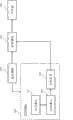
以下配合图式对本发明温度增益控制装置及其方法作进一步说明,首先,先针对本发明温度增益控制装置作说明,请参阅图1,图1为本发明温度增益控制装置的方块图,包含:感应模块110、BIOS模块120、加热模块130及加热器140。其中,感应模块110用以持续感应设备中的工作环境温度,并将所感应到的工作环境温度与预先设置的第一温度参数进行比对,且根据比对结果产生控制信号。在实际实施上,感应模块110可使用温度感应器(Temperature Sensor),例如:热敏电阻、温度感测IC(AD 590)......等等,用以获得工作环境温度,由于通过温度感应器感应工作环境温度为习知技术,故在此将不再多作赘述。接着,感应模块110感应到工作环境温度后,即可通过比较器来比对此工作环境温度与第一温度参数,并且在工作环境温度位于第一温度参数的范围外时产生控制信号,如:ON。或是工作环境温度位于第一温度参数的范围内时产生控制信号,如:OFF。The temperature gain control device of the present invention and its method are further described below in conjunction with the drawings. First, the temperature gain control device of the present invention is described first. Please refer to FIG. 1. FIG. 1 is a block diagram of the temperature gain control device of the present invention, including: The
BIOS模块120用以允许使用者设定并储存第二温度参数,并持续将感应模块110所感应到的工作环境温度偏移一个间隔数值后,再将偏移后的工作环境温度与此第二温度参数进行比对,且根据比对结果选择控制模式以驱动控制芯片产生相应的脉波宽度调变(Pulse Width Modulation,PWM)信号,由于此PWM信号为习知技术,故在此不再多作赘述。在实际实施上,使用者是通过BIOS的操作界面来设定第二温度参数,所述BIOS储存于非挥发性内存,例如:flash、EPROM、EEPROM......等等,而第二温度参数则储存于挥发性内存,如:CMOS RAM之中。另外,所述控制模式为第二温度参数与不同的PWM信号的对应,举例来说,控制模式可包含一个以上的情况,第一个情况为:第二温度参数在“10度″时,产生PWM信号为“40%″(PWM Duty Cycle)、第二温度参数在“30度″时,产生PWM信号为“20%″......等等。特别要说明的是,本发明并未以上述举例限定在控制模式中,其第二温度参数与所产生的PWM信号的对应关系。The
承上所述,当BIOS模块120根据比对结果选择控制模式后,将驱动控制芯片产生相应的PWM信号,所述控制芯片为具有PWM信号控制机制的超级(Super)I/O芯片,如:编号为W83627EHF的芯片。由于此控制芯片为习知技术,故在此不再多作说明。特别要说明的是,本发明可应用此习知控制芯片的智能风扇控制(Smart Fan Control)来控制加热器,不过这个智能风扇控制(Smart Fan Control)无法支援“0度以下″的工作环境温度,因此,BIOS模块120会将感应模块110所感应到的工作环境温度偏移(Offset)一个间隔数值(例如:数值“128″),使工作环境温度维持在正温度(例如:“0度″或“0度″以上)后,再应用于智能风扇控制中。举例来说,假设感应模块110能够感应的工作环境温度的范围为“-128度″至“127度″,其对应的定址为8位元的二进制码(8-bit binary codes),范围为“1000,0000″至“0111,1111″。由于智能风扇控制器中无法正确处理负数的二进制码,因此,BIOS模块120可将“1000,0000″进行偏移成为“0000,0000″、将“1000,0001″进行偏移成为“0000,0001″、并以此类推将“0111,1111″进行偏移成为“1111,1111″。换句话说,便是将具有代表负数的二进制码转换成仅代表正数的二进制码(例如:定址为“-128~127″转为“0~255″)。As mentioned above, after the
如此一来,所述控制芯片的智能风扇控制即可以此产生相应的PWM信号。举例来说,假设工作环境温度为“-128度″,经由上述偏移处理后可得到二进制码为“0000,0000″,接下来,以公式计算所产生的PWM信号,其公式可为:此8位元的二进制码/255*100%,且进行反相后的数值,以此例而言,工作环境温度为“-128度″,经由偏移处理后其十进制的值为“0″,接着带入上述公式计算后得到数值为“0%″(即:0/255*100%=0%),再将此数值“0%″反相后即可得到PWM信号为“100%″。特别要说明的是,本发明并未以上述公式限定PWM信号的计算方式。In this way, the intelligent fan control of the control chip can generate corresponding PWM signals. For example, assuming that the working environment temperature is "-128 degrees", the binary code can be obtained as "0000,0000" after the above-mentioned offset processing. Next, calculate the generated PWM signal with the formula, the formula can be: 8-bit binary code/255*100%, and the value after inversion. In this example, the working environment temperature is "-128 degrees", and its decimal value is "0" after offset processing. Then put it into the above formula to calculate and get the value "0%" (ie: 0/255*100%=0%), and then invert the value "0%" to get the PWM signal as "100%". It should be noted that the present invention does not limit the calculation method of the PWM signal by the above formula.
加热模块130用以根据控制信号产生输出功率,且于PWM信号产生后,同时搭配感应模块110所产生的控制信号,以及BIOS模块120所产生的PWM信号来调整输出功率。在实际实施上,假设仅产生控制信号,则加热模块130将根据此控制信号产生相应的输出功率,例如:控制信号为“OFF″产生“0%″的输出功率;控制信号为“ON″则产生“100%″的输出功率。接着,当BIOS模块120产生PWM信号后,假设控制信号为“ON″、PWM信号为“100%″,加热模块130将同时搭配控制信号及PWM信号以调整其输出功率,如:将输出功率调整为“100%″;假设控制信号为“ON″、PWM信号为“50%″,加热模块130则会调整为“50%″的输出功率......并以此类推。特别要说明的是,假设控制信号为“OFF″,则PWM信号无论是否为“0%″,加热模块130将因此调整为最小的输出功率(例如:“0%″)或关闭加热器140,如此一来,即便BIOS模块120发生异常而产生异常的PWM信号,也不至于使加热器140持续加热而对电子元件100造成不良影响。The
加热器140设置于电子元件100周围,用以接收加热模块130所产生的输出功率,并且根据此输出功率对电子元件100进行加热。所述加热器可为软板电热片,此软板电热片设置于电子设备中的电子元件100的周围,用以提高电子元件100的工作环境温度。由于此加热器140为习知技术,故在此将不再多作赘述。特别要说明的是,本发明并未以此限定加热器140的数量与种类。The
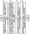
如图2所示,图2为本发明温度增益控制方法的方法流程图,其步骤包括:持续感应设备中的工作环境温度,并将此工作环境温度与预先设置的第一温度参数进行比对,且根据比对结果产生控制信号(步骤210);允许设定并储存第二温度参数,并持续将其工作环境温度偏移一个间隔数值后,将偏移后的此工作环境温度与第二温度参数进行比对,且根据比对结果选择控制模式以驱动控制芯片产生相应的PWM信号(步骤220);根据控制信号产生输出功率,且于PWM信号产生后,同时搭配此控制信号及PWM信号调整其输出功率(步骤230);加热器设置于电子元件100周围,用以接收输出功率,并且根据此输出功率对电子元件100进行加热(步骤240)。通过上述步骤,即可通过感应工作环境温度,并且根据此工作环境温度产生控制信号及PWM信号,用以动态控制设置于电子元件100周围的加热器进行加热。As shown in Figure 2, Figure 2 is a method flow chart of the temperature gain control method of the present invention, the steps of which include: continuously sensing the working environment temperature in the device, and comparing the working environment temperature with the preset first temperature parameter , and generate a control signal according to the comparison result (step 210); allow to set and store the second temperature parameter, and continue to shift the working environment temperature by an interval value, and then compare the shifted working environment temperature with the second Comparing the temperature parameters, and selecting a control mode according to the comparison result to drive the control chip to generate a corresponding PWM signal (step 220); generating output power according to the control signal, and matching the control signal and the PWM signal at the same time after the PWM signal is generated Adjust its output power (step 230); the heater is disposed around the electronic component 100 to receive the output power, and heat the electronic component 100 according to the output power (step 240). Through the above steps, the temperature of the working environment can be sensed, and a control signal and a PWM signal can be generated according to the temperature of the working environment to dynamically control the heater disposed around the electronic component 100 for heating.
以下配合图3至图5以实施例的方式进行如下说明,请先参阅图3,图3为本发明的感应模块的示意图,其感应模块110包含:温度参数储存器111、温度感应器112及比较器113。特别要说明的是,本发明并未以此限定感应模块110仅通过比较器113来产生控制信号,以及感应模块110所包含的电子元件100数量及类型。The following description will be made in the form of an embodiment in conjunction with Fig. 3 to Fig. 5. Please refer to Fig. 3 first. Fig. 3 is a schematic diagram of the sensing module of the present invention.
当电子设备仅通电且未运作或是正常运作时,温度感应器112皆可用以持续感应工作环境温度,比较器113会将此工作环境温度与温度参数储存器111内所预先储存的第一温度参数进行比对,使感应模块110根据其比对结果产生控制信号。假设第一温度参数设定为“0度;20度″,其代表当工作环境温度在“0度″以下时产生控制信号,如:ON;当工作环境温度在“20度″以上时则产生控制信号,如:OFF。When the electronic device is only powered on and not operating or operating normally, the
接着,加热模块130在接收到控制信号为“ON″时,将产生输出功率以启动加热器140进行加热。在加热过程中,温度感应器112所感应到的工作环境温度将持续升高,并且在升高至“20度″时,感应模块110产生控制信号“OFF″,此时加热模块130将降低产生的输出功率,甚至所产生的输出功率为“0″,用以使加热器140降低加热温度,甚至直接停止加热。Next, when the
接下来,请参阅图4,图4为本发明BIOS模块的示意图。BIOS模块120包含:内存单元121、BIOS单元122及控制芯片123。所述内存单元121用以储存第二温度参数,其可为挥发性内存,如:CMOS RAM。在实际实施上,内存单元121除了储存第二温度参数之外,亦同时储存BIOS相关的其他设定参数。Next, please refer to FIG. 4 , which is a schematic diagram of the BIOS module of the present invention. The
BIOS单元122用以储存电子设备的BIOS,并且提供操作界面供使用者进行相关设定,如:第二温度参数。由于所述BIOS为习知技术,故习知部分在此将不再多作赘述,而仅就差异处进行说明。本发明在此BIOS中新增偏移计算,用以将温度感应器112所感应到的二进制温度值进行偏移计算,并且将计算得出的数值进行反相处理,以便适用于控制芯片123的智能风扇控制,用以使控制芯片123产生合适的PWM信号,进而让加热模块130根据此PWM信号来控制加热器140。在实际实施上,控制芯片123可选用编号为W83627EHF的超级(Super)I/O芯片,温度感应器112可与此控制芯片123的AUXTIN脚位、CPUTIN脚位及SYSTIN脚位(例如:“pin 102″、“pin 103″及“pin 104″)其中之一电性连接;而加热模块130则可与此控制芯片123的AUXFANOUT脚位、CPUFANOUT0,1脚位及SYSFANOUT脚位(例如:“pin 7″、“pin 115;pin 120″及“pin 116″)其中之一电性连接。换句话说,在实际实施上,温度感应器112与加热器140最多可同时连接三组,以同时连接三组为例,控制芯片123可根据三组温度感应器112所感应到的三组工作环境温度,同样使用前述的方式用以分别产生相应的三组PWM信号,以便通过各组PWM信号来分别控制相应的加热器140。The
如图5所示意,图5为本发明加热模块的示意图。在实际实施上,加热模块130可包含:温度控制开关131、PWM控制开关132及功率控制器133。加热模块130通过温度控制开关131接收感应模块110所传送的控制信号、通过PWM控制开关132接收BIOS模块120所传送的PWM信号,以及通过功率控制器133根据其控制信号产生输出功率,且于PWM信号产生后,同时搭配控制信号及PWM信号调整其输出功率,以使加热器140在PWM信号产生前根据所产生的输出功率进行加热,或在PWM信号产生后根据调整后的输出功率进行加热。特别要说明的是,虽然应用本发明的加热器140会根据所述控制信号与PWM信号进行加热或停止加热,然而,其控制信号与PWM信号主要的差异在于控制信号的电压可调变,而PWM信号则是定电压。As shown in Fig. 5, Fig. 5 is a schematic diagram of the heating module of the present invention. In practice, the
综上所述,可知本发明与先前技术之间的差异在于通过感应工作环境温度,并且根据此工作环境温度产生控制信号及PWM信号,用以动态控制设置于电子元件100周围的加热器进行加热,藉由此一技术手段可以解决先前技术所存在的问题,进而在工作环境温度过低时,达成提高电子元件100的稳定性的技术功效。In summary, it can be seen that the difference between the present invention and the prior art lies in that the temperature of the working environment is sensed, and a control signal and a PWM signal are generated according to the temperature of the working environment to dynamically control the heater arranged around the electronic component 100 for heating. , by means of this technical means can solve the problems existing in the prior art, and then achieve the technical effect of improving the stability of the electronic component 100 when the temperature of the working environment is too low.
虽然本发明以前述的实施例揭露如上,然其并非用以限定本发明,任何熟习相像技艺者,在不脱离本发明的精神和范围内,当可作些许的更动与润饰,因此本发明的专利保护范围须视本说明书所附的申请专利范围所界定者为准。Although the present invention is disclosed above with the foregoing embodiments, it is not intended to limit the present invention. Any person familiar with similar skills may make some changes and modifications without departing from the spirit and scope of the present invention. Therefore, the present invention The scope of patent protection shall be defined by the scope of patent application attached to this specification.
Claims (17)
Priority Applications (1)
| Application Number | Priority Date | Filing Date | Title |
|---|---|---|---|
| CN 201010103602CN102137584B (en) | 2010-01-27 | 2010-01-27 | Temperature gain control device and method thereof |
Applications Claiming Priority (1)
| Application Number | Priority Date | Filing Date | Title |
|---|---|---|---|
| CN 201010103602CN102137584B (en) | 2010-01-27 | 2010-01-27 | Temperature gain control device and method thereof |
Publications (2)
| Publication Number | Publication Date |
|---|---|
| CN102137584Atrue CN102137584A (en) | 2011-07-27 |
| CN102137584B CN102137584B (en) | 2013-05-01 |
Family
ID=44297210
Family Applications (1)
| Application Number | Title | Priority Date | Filing Date |
|---|---|---|---|
| CN 201010103602ActiveCN102137584B (en) | 2010-01-27 | 2010-01-27 | Temperature gain control device and method thereof |
Country Status (1)
| Country | Link |
|---|---|
| CN (1) | CN102137584B (en) |
Cited By (2)
| Publication number | Priority date | Publication date | Assignee | Title |
|---|---|---|---|---|
| CN104703302A (en)* | 2013-12-09 | 2015-06-10 | 启碁科技股份有限公司 | Heating systems for electronic devices |
| CN105228412A (en)* | 2015-08-24 | 2016-01-06 | 中磊电子(苏州)有限公司 | Heater |
Family Cites Families (2)
| Publication number | Priority date | Publication date | Assignee | Title |
|---|---|---|---|---|
| JP4192986B2 (en)* | 2006-10-20 | 2008-12-10 | ソニー株式会社 | Temperature control apparatus and method, and program |
| KR100985961B1 (en)* | 2008-05-26 | 2010-10-06 | 엘에스산전 주식회사 | Temperature control module and method |
- 2010
- 2010-01-27CNCN 201010103602patent/CN102137584B/enactiveActive
Cited By (4)
| Publication number | Priority date | Publication date | Assignee | Title |
|---|---|---|---|---|
| CN104703302A (en)* | 2013-12-09 | 2015-06-10 | 启碁科技股份有限公司 | Heating systems for electronic devices |
| CN105228412A (en)* | 2015-08-24 | 2016-01-06 | 中磊电子(苏州)有限公司 | Heater |
| US9791173B2 (en) | 2015-08-24 | 2017-10-17 | Sercomm Corporation | Heating device having heating transistor unit |
| CN105228412B (en)* | 2015-08-24 | 2018-09-14 | 中磊电子(苏州)有限公司 | Heating device |
Also Published As
| Publication number | Publication date |
|---|---|
| CN102137584B (en) | 2013-05-01 |
Similar Documents
| Publication | Publication Date | Title |
|---|---|---|
| US7791328B2 (en) | Method and system for calibrating a motor control circuit to improve temperature measurement in an electrical motor | |
| CN109416566A (en) | Use the predictive thermal control management of temperature and power sensor | |
| CN103763803B (en) | The control method of electromagnetic resonance control circuit, electromagnetic heater and transistor | |
| CN102748312A (en) | Control device for rotating speed of fan | |
| US9791173B2 (en) | Heating device having heating transistor unit | |
| CN202840493U (en) | Motor, controller and overheat protection circuit of power driving module of motor | |
| CN101557092A (en) | Protection circuit and circuit protection method | |
| CN102904212A (en) | protect the circuit | |
| US20170351306A1 (en) | Computer power supply device having fan control circuit for cooling standby power source unit in state in which computer is turned off, and operating method | |
| US8640968B2 (en) | Temperature gain control device and method thereof | |
| CN102137584B (en) | Temperature gain control device and method thereof | |
| CN104244481B (en) | The method for heating and controlling of electromagnetic induction heater and electromagnetic induction heater | |
| CN103309373B (en) | Low-temperature single chip microcomputer starting and working method and low-temperature running single chip microcomputer system for achieving method | |
| KR102238251B1 (en) | Steam generator with low energy consumption | |
| CN205119164U (en) | Temperature protection system and high -frequency heating apparatus | |
| TWI402644B (en) | Temperature gain control device and method thereof | |
| TWI277713B (en) | Method and equipment for the control of a ventilator | |
| TW201441818A (en) | Flash memory device capable of regulating temperature | |
| JP6021461B2 (en) | Outdoor unit for air conditioner and control method thereof | |
| KR102020364B1 (en) | Air conditioner | |
| CN117192924A (en) | Fixing device protection equipment and printer | |
| CN107577261A (en) | A kind of temp control switch circuit | |
| JP4919440B2 (en) | Glass system, processing device and program | |
| CN104237724B (en) | Detection card and detection system for fan card | |
| CN101470450B (en) | Cooling fan control circuit |
Legal Events
| Date | Code | Title | Description |
|---|---|---|---|
| C06 | Publication | ||
| PB01 | Publication | ||
| C10 | Entry into substantive examination | ||
| SE01 | Entry into force of request for substantive examination | ||
| C14 | Grant of patent or utility model | ||
| GR01 | Patent grant |