CN102132479A - Power supply unit and lighting unit - Google Patents
Power supply unit and lighting unitDownload PDFInfo
- Publication number
- CN102132479A CN102132479ACN200980133130XACN200980133130ACN102132479ACN 102132479 ACN102132479 ACN 102132479ACN 200980133130X ACN200980133130X ACN 200980133130XACN 200980133130 ACN200980133130 ACN 200980133130ACN 102132479 ACN102132479 ACN 102132479A
- Authority
- CN
- China
- Prior art keywords
- voltage
- unit
- power supply
- output
- circuit
- Prior art date
- Legal status (The legal status is an assumption and is not a legal conclusion. Google has not performed a legal analysis and makes no representation as to the accuracy of the status listed.)
- Granted
Links
Images


Classifications
- H—ELECTRICITY
- H02—GENERATION; CONVERSION OR DISTRIBUTION OF ELECTRIC POWER
- H02M—APPARATUS FOR CONVERSION BETWEEN AC AND AC, BETWEEN AC AND DC, OR BETWEEN DC AND DC, AND FOR USE WITH MAINS OR SIMILAR POWER SUPPLY SYSTEMS; CONVERSION OF DC OR AC INPUT POWER INTO SURGE OUTPUT POWER; CONTROL OR REGULATION THEREOF
- H02M3/00—Conversion of DC power input into DC power output
- H02M3/22—Conversion of DC power input into DC power output with intermediate conversion into AC
- H02M3/24—Conversion of DC power input into DC power output with intermediate conversion into AC by static converters
- H02M3/28—Conversion of DC power input into DC power output with intermediate conversion into AC by static converters using discharge tubes with control electrode or semiconductor devices with control electrode to produce the intermediate AC
- H02M3/325—Conversion of DC power input into DC power output with intermediate conversion into AC by static converters using discharge tubes with control electrode or semiconductor devices with control electrode to produce the intermediate AC using devices of a triode or a transistor type requiring continuous application of a control signal
- H02M3/335—Conversion of DC power input into DC power output with intermediate conversion into AC by static converters using discharge tubes with control electrode or semiconductor devices with control electrode to produce the intermediate AC using devices of a triode or a transistor type requiring continuous application of a control signal using semiconductor devices only
- H02M3/33507—Conversion of DC power input into DC power output with intermediate conversion into AC by static converters using discharge tubes with control electrode or semiconductor devices with control electrode to produce the intermediate AC using devices of a triode or a transistor type requiring continuous application of a control signal using semiconductor devices only with automatic control of the output voltage or current, e.g. flyback converters
- H—ELECTRICITY
- H05—ELECTRIC TECHNIQUES NOT OTHERWISE PROVIDED FOR
- H05B—ELECTRIC HEATING; ELECTRIC LIGHT SOURCES NOT OTHERWISE PROVIDED FOR; CIRCUIT ARRANGEMENTS FOR ELECTRIC LIGHT SOURCES, IN GENERAL
- H05B45/00—Circuit arrangements for operating light-emitting diodes [LED]
- H05B45/30—Driver circuits
- H05B45/37—Converter circuits
- H05B45/3725—Switched mode power supply [SMPS]
- H05B45/382—Switched mode power supply [SMPS] with galvanic isolation between input and output
- H—ELECTRICITY
- H05—ELECTRIC TECHNIQUES NOT OTHERWISE PROVIDED FOR
- H05B—ELECTRIC HEATING; ELECTRIC LIGHT SOURCES NOT OTHERWISE PROVIDED FOR; CIRCUIT ARRANGEMENTS FOR ELECTRIC LIGHT SOURCES, IN GENERAL
- H05B45/00—Circuit arrangements for operating light-emitting diodes [LED]
- H05B45/50—Circuit arrangements for operating light-emitting diodes [LED] responsive to malfunctions or undesirable behaviour of LEDs; responsive to LED life; Protective circuits
- Y—GENERAL TAGGING OF NEW TECHNOLOGICAL DEVELOPMENTS; GENERAL TAGGING OF CROSS-SECTIONAL TECHNOLOGIES SPANNING OVER SEVERAL SECTIONS OF THE IPC; TECHNICAL SUBJECTS COVERED BY FORMER USPC CROSS-REFERENCE ART COLLECTIONS [XRACs] AND DIGESTS
- Y02—TECHNOLOGIES OR APPLICATIONS FOR MITIGATION OR ADAPTATION AGAINST CLIMATE CHANGE
- Y02B—CLIMATE CHANGE MITIGATION TECHNOLOGIES RELATED TO BUILDINGS, e.g. HOUSING, HOUSE APPLIANCES OR RELATED END-USER APPLICATIONS
- Y02B20/00—Energy efficient lighting technologies, e.g. halogen lamps or gas discharge lamps
- Y02B20/30—Semiconductor lamps, e.g. solid state lamps [SSL] light emitting diodes [LED] or organic LED [OLED]
Landscapes
- Engineering & Computer Science (AREA)
- Power Engineering (AREA)
- Circuit Arrangement For Electric Light Sources In General (AREA)
- Dc-Dc Converters (AREA)
- Led Devices (AREA)
Abstract
Description
Translated fromChinese技术领域technical field
本发明涉及即使市电的电压波动时也可以继续正常动作的电源装置和具有该电源装置的照明装置。The present invention relates to a power supply device capable of continuing to operate normally even when the voltage of commercial power fluctuates, and a lighting device provided with the power supply device.
背景技术Background technique
近年来,研制了各种用途的把发光二极管(以下称为LED)作为光源的照明装置,并且用来替换采用了白炽灯或荧光灯等以往光源的照明装置。此外,在头灯或尾灯等车载用照明装置中,把LED作为光源的照明装置已经商品化。In recent years, lighting devices using light-emitting diodes (hereinafter referred to as LEDs) as light sources have been developed for various purposes, and are used to replace lighting devices using conventional light sources such as incandescent lamps and fluorescent lamps. In addition, among vehicle-mounted lighting devices such as headlights and tail lights, lighting devices using LEDs as light sources have already been commercialized.
在把LED作为光源的照明装置所采用的电源电路(电源装置)中,由于LED与白炽灯等以往光源的特性不同,所以需要进行与采用以往光源的照明装置不同的电源控制。例如,由于装置的电气特性需要由恒定电流来驱动LED,所以把LED作为光源的照明装置的电源电路不是通常的恒定电压输出方式,而是需要电压/电流的输出特性相对于电压的波动使电流恒定的恒定电流输出方式。In a power supply circuit (power supply unit) used in a lighting device using an LED as a light source, LEDs have different characteristics from conventional light sources such as incandescent lamps, so different power supply control is required from lighting devices using conventional light sources. For example, because the electrical characteristics of the device require a constant current to drive the LED, the power supply circuit of the lighting device using the LED as the light source is not the usual constant voltage output mode, but requires the output characteristics of the voltage/current relative to the fluctuation of the voltage to make the current Constant constant current output mode.
另一方面,由于LED的故障模式具有开路模式和短路模式两种模式,所以电源电路需要设置过载保护电路,该过载保护电路对由LED的故障等导致的过电流或过电压等过载状态进行保护。例如通过检测电源电路内的开关变压器初级的开关元件的过电流,来检测开关变压器次级的负载的过电压或过电流等过载状态,在处于过载状态的情况下,停止电源输出,从而实现过载保护功能。On the other hand, since the failure mode of the LED has two modes: open mode and short mode, the power supply circuit needs to be equipped with an overload protection circuit that protects against overload conditions such as overcurrent or overvoltage caused by LED failure, etc. . For example, by detecting the overcurrent of the primary switching element of the switching transformer in the power supply circuit, the overload state such as overvoltage or overcurrent of the secondary load of the switching transformer is detected, and in the case of overload, the power supply output is stopped to achieve overload. Protective function.
此外,在把光源以外的装置作为负载的反相控制方式的电源装置中,公开了一种使反相输出持续停止的过电流保护装置(参照专利文献1:日本专利公开公报特开平4-217877号),该过电流保护装置具有闩锁电路,当反相的输入电流在规定值以上时,由过电流检测电路输出异常判断信号,利用该异常判断信号来进行设置,并且直到输入复位信号为止保持该状态。In addition, in a power supply device of an inversion control method in which a device other than a light source is used as a load, an overcurrent protection device that continuously stops the inversion output is disclosed (see Patent Document 1: Japanese Patent Laid-Open Publication No. Hei 4-217877 No.), the overcurrent protection device has a latch circuit. When the reverse input current is above a specified value, the overcurrent detection circuit outputs an abnormality judgment signal, which is used to set the abnormality judgment signal, and until the reset signal is input Keep it that way.
这种过载保护功能不仅具有如上所述的闩锁式,还具有自动恢复式等。闩锁式过载保护功能在过载保护功能动作的情况下,当解除过载保护功能时需要暂时切断(断开)市电等输入电源。另一方面,自动恢复式过载保护功能如果解除处于过载状态的开关元件的过电流状态,则再次开始开关动作,从而恢复电源输出。因此,根据发生过电流的原因,自动恢复式会陷入发生过载、停止电源输出、解除过载原因、恢复电源输出、发生过载、停止电源输出这样的循环动作,难以保证电源装置(电源电路)或照明装置的安全性。因此,与自动恢复式相比,大多采用闩锁式过载保护功能。This overload protection function has not only the above-mentioned latch type but also an automatic recovery type and the like. In the case of the latch-type overload protection function, when the overload protection function is activated, it is necessary to temporarily cut off (disconnect) the input power such as commercial power when releasing the overload protection function. On the other hand, the automatic recovery type overload protection function restarts the switching operation when the overcurrent state of the switching element in the overload state is released, thereby restoring the power supply output. Therefore, depending on the cause of the overcurrent, the auto-recovery type will fall into a cycle of overload, stop power output, remove the cause of overload, restore power output, overload, stop power output, and it is difficult to ensure the power supply (power circuit) or lighting. device security. Therefore, compared with the automatic recovery type, most of them adopt the latch type overload protection function.
然而,在由开关元件对开关变压器的初级进行开关的电源电路中,当市电(输入电源)的电压降低时,具有用于向负载提供规定电能的输入电流、即流过开关元件的电流增加的特性,成为与过载状态相同的状态。因此,在由于某种原因而导致发生了市电瞬时停电或瞬时电压降低的情况下,虽然实际上不是由于LED等故障而导致的过载状态,但是流过开关元件的电流增加,造成过载保护功能动作而使电源输出停止。闩锁式过载保护功能即使在市电恢复正常之后,仍然继续保持电源输出停止状态。However, in a power supply circuit in which the primary side of a switching transformer is switched by a switching element, when the voltage of the commercial power (input power supply) decreases, there is an input current for supplying predetermined electric energy to a load, that is, the current flowing through the switching element increases. characteristics, it becomes the same state as the overload state. Therefore, in the case of a momentary power failure or momentary voltage drop in the commercial power for some reason, although it is not actually an overload state caused by a failure of the LED, etc., the current flowing through the switching element increases, causing the overload protection function action to stop the power output. The latch-type overload protection function keeps the power output stopped even after the utility power returns to normal.
此外,一般来说,具有恒定电流输出方式的恒定电流电路相对于容许范围内的输出电压的波动,能够以恒定电流动作模式进行动作来输出恒定电流,并且当输出电压增加而超出容许范围时,从恒定电流动作模式转变成相对于输出电流的波动使输出电压恒定的恒定电压动作模式。并且,当由于市电瞬时停电或瞬时电压降低使提供给恒定电流电路的电压降低时,在恒定电流电路内生成的基准电压也降低,从表面上看成为与输出电压(负载的电压)增加的状态相同的状态,从而导致恒定电流电路从恒定电流动作模式转变成恒定电压动作模式。在该状态下,即使市电恢复正常,由于恒定电流电路继续以恒定电压动作模式进行动作,所以电源电路不能提供LED所需要的电流,使LED以比正常亮度暗的状态持续亮灯。In addition, in general, a constant current circuit with a constant current output method can operate in a constant current operation mode to output a constant current with respect to fluctuations in the output voltage within the allowable range, and when the output voltage increases beyond the allowable range, Switches from the constant current operation mode to the constant voltage operation mode in which the output voltage is kept constant against fluctuations in the output current. Also, when the voltage supplied to the constant current circuit decreases due to a momentary power failure or momentary voltage drop in the commercial power supply, the reference voltage generated in the constant current circuit also decreases, apparently increasing in proportion to the output voltage (voltage of the load). The state of the state is the same, thus causing the constant current circuit to change from the constant current operation mode to the constant voltage operation mode. In this state, even if the commercial power returns to normal, since the constant current circuit continues to operate in the constant voltage operation mode, the power supply circuit cannot provide the current required by the LED, making the LED continue to light up with a darker than normal brightness.
发明内容Contents of the invention
鉴于上述问题,本发明的目的在于提供即使市电的电压波动时也可以继续正常动作的电源装置和具有该电源装置的照明装置。In view of the above problems, an object of the present invention is to provide a power supply device that can continue to operate normally even when the voltage of commercial power fluctuates, and a lighting device including the power supply device.
本发明提供一种电源装置,其包括:转换部,将交流转换成直流;开关元件,使从所述转换部向变压器的初级提供的直流电导通或断开(switching);过载检测部,检测设置在所述变压器的次级上的负载的过载状态;以及过载保护部,当由所述过载检测部检测出过载状态时,使所述开关元件停止动作,并且保持停止状态,所述电源装置的特征在于还包括:电压检测部,检测所述转换部输出的电压;以及控制部,当所述电压检测部检测出的电压比第一阈值低时,进行控制以使所述开关元件停止动作,所述第一阈值比由所述过载检测部检测出过载状态时的所述转换部的输出电压值大。The present invention provides a power supply device, which includes: a conversion part that converts an alternating current into a direct current; a switching element that switches on or off (switching) the direct current supplied from the conversion part to the primary side of a transformer; an overload detection part that detects an overload state of a load provided on the secondary side of the transformer; and an overload protection unit that stops the operation of the switching element and maintains the stopped state when the overload state is detected by the overload detection unit, the power supply device The present invention is characterized by further comprising: a voltage detection unit detecting the voltage output by the conversion unit; and a control unit, when the voltage detected by the voltage detection unit is lower than a first threshold value, controlling to stop the operation of the switching element The first threshold value is greater than the output voltage value of the conversion unit when the overload state is detected by the overload detection unit.
本发明的电源装置的特征在于,在所述开关元件停止动作的情况下,当由所述电压检测部检测出的电压超过比所述第一阈值大的第二阈值时,所述控制部使所述开关元件再次开始动作。In the power supply device according to the present invention, when the switching element stops operating, when the voltage detected by the voltage detection unit exceeds a second threshold value greater than the first threshold value, the control unit causes The switching element starts operating again.
本发明的电源装置的特征在于还包括:调节部,利用从所述变压器次级提供的电压来生成直流电压;恒定电流控制部,利用由所述调节部生成的直流电压来进行动作,并且对由所述直流电压生成的基准电压和将流过负载的电流转换后的电压进行比较,来向负载提供恒定电流;以及输出停止部,当向所述调节部提供的电压比第三阈值低时,使所述恒定电流控制部停止动作。The power supply device of the present invention is characterized in that it further includes: an adjustment unit that generates a DC voltage using the voltage supplied from the secondary side of the transformer; a constant current control unit that operates using the DC voltage generated by the adjustment unit, and controls A reference voltage generated from the direct current voltage is compared with a voltage obtained by converting a current flowing through the load to supply a constant current to the load; and an output stop unit, when the voltage supplied to the adjustment unit is lower than a third threshold value to stop the operation of the constant current control unit.
本发明的电源装置的特征在于,所述输出停止部通过使所述调节部停止动作,来使所述恒定电流控制部停止动作。In the power supply device according to the present invention, the output stop unit stops the operation of the constant current control unit by stopping the operation of the adjustment unit.
本发明的电源装置的特征在于,把发光二极管作为负载。The power supply device of the present invention is characterized in that a light emitting diode is used as a load.
本发明提供一种照明装置,其特征在于包括发光二极管和上述发明的电源装置。The present invention provides an illuminating device, which is characterized by comprising a light emitting diode and the power supply device of the above invention.
按照本发明,由电压检测部检测转换部(例如对从市电输入的交流电进行整流使其平滑化,并转换成直流)输出的电压。即,电压检测部检测市电瞬时停电或瞬时电压降低的发生。并且,当电压检测部检测出的电压比第一阈值低时,控制部使开关元件停止动作。在这种情况下,使第一阈值比由过载检测部检测出过载状态时的转换部的输出电压值大。过载检测部例如把施加给负载的过电压或流过负载的过电流作为过载状态来进行检测。此外,过载检测部可以根据流过开关元件的电流的大小,来检测出过载状态。由此,在由于市电瞬时停电或瞬时电压降低,使流过开关元件的电流增加,由过载保护部使开关元件停止动作并保持停止状态之前,控制部使开关元件停止动作,并且使过载保护部不动作。而且,当市电恢复正常时,由于电压检测部检测出的电压比第一阈值高,所以控制部使开关元件再次开始动作。由此,即使市电的电压波动时也可以继续正常动作。According to the present invention, the voltage detection unit detects the output voltage of the conversion unit (for example, rectifies and smoothes AC power input from a commercial power supply, and converts it to DC). That is, the voltage detection unit detects the occurrence of an instantaneous power failure or an instantaneous voltage drop. And, when the voltage detected by the voltage detection unit is lower than the first threshold value, the control unit stops the operation of the switching element. In this case, the first threshold value is made larger than the output voltage value of the conversion unit when the overload detection unit detects the overload state. The overload detection unit detects, for example, an overvoltage applied to the load or an overcurrent flowing through the load as an overload state. In addition, the overload detection unit can detect the overload state based on the magnitude of the current flowing through the switching element. Thus, before the current flowing through the switching element increases due to the instantaneous power failure or instantaneous voltage drop of the commercial power supply, and the overload protection section stops the switching element from operating and maintains the stopped state, the control section stops the switching element and activates the overload protection device. No action. Then, when the commercial power returns to normal, since the voltage detected by the voltage detection unit is higher than the first threshold value, the control unit restarts the operation of the switching element. Accordingly, normal operation can be continued even when the voltage of the commercial power fluctuates.
按照本发明,在开关元件停止动作的情况下,当由电压检测部检测出的电压超过比第一阈值大的第二阈值时,控制部使开关元件再次开始动作。即,通过在使开关元件停止动作的第一阈值(低电压检测阈值)和使开关元件再次开始动作的第二阈值(低电压解除阈值)之间具有所需要的电压宽度,当市电的瞬时电压波动在短时间内重复时,可以防止开关元件在短时间内重复停止、再次打开的动作,并且可以高精度地检测市电瞬时停电或瞬时电压降低。According to the present invention, when the switching element stops operating, the control section restarts the switching element when the voltage detected by the voltage detecting section exceeds the second threshold value higher than the first threshold value. That is, by having a required voltage width between the first threshold (low voltage detection threshold) at which the switching element stops operating and the second threshold (low voltage release threshold) at which the switching element resumes operation, when the commercial power is instantaneous When voltage fluctuations are repeated in a short period of time, it is possible to prevent switching elements from repeatedly stopping and opening again in a short period of time, and it is possible to detect momentary power failures or momentary voltage drops in commercial power with high precision.
按照本发明,调节部利用从变压器次级提供的电压来生成直流电压,恒定电流控制部利用由调节部生成的直流电压来进行动作,并且对由生成的直流电压生成的基准电压和将流过负载(例如LED)的电流转换后的电压进行比较,来向负载提供恒定电流。当向调节部提供的电压比第三阈值低时,输出停止部使恒定电流控制部停止动作。由此,当由于市电瞬时停电或瞬时电压降低,使提供给调节部的电压比第三阈值低时,可以防止因恒定电流控制部内生成的基准电压也降低,从表面上看成为与输出电压(负载的电压)增加的状态相同的状态,而使恒定电流控制部从恒定电流动作模式转变成恒定电压动作模式。并且,当市电恢复正常时,提供给调节部的电压比第三阈值大,使暂时停止动作的恒定电流控制部再次开始动作。在这种情况下,由于恒定电流控制部正常启动,以恒定电流动作模式动作,所以可以提供例如LED所需要的电流,从而可以使LED以正常的亮度亮灯。According to the present invention, the regulator generates a DC voltage using the voltage supplied from the secondary side of the transformer, the constant current control unit operates using the DC voltage generated by the regulator, and the reference voltage generated from the generated DC voltage and the current flow The converted voltage of the current of the load (such as LED) is compared to provide a constant current to the load. When the voltage supplied to the adjustment unit is lower than the third threshold, the output stop unit stops the constant current control unit from operating. In this way, when the voltage supplied to the regulator is lower than the third threshold due to the instantaneous power failure or voltage drop of the mains, it is possible to prevent the reference voltage generated in the constant current control section from also decreasing, which appears to be the same as the output voltage. (The voltage of the load) is the same as the state of the increase, and the constant current control unit is changed from the constant current operation mode to the constant voltage operation mode. Moreover, when the commercial power returns to normal, the voltage supplied to the regulating unit is greater than the third threshold value, so that the constant current control unit whose operation was temporarily stopped starts operating again. In this case, since the constant current control unit normally activates and operates in the constant current operation mode, it is possible to supply the current required by the LED, for example, and to turn on the LED with normal brightness.
按照本发明,输出停止部通过使调节部停止动作,来使恒定电流控制部停止动作。由此,当由于市电瞬时停电或瞬时电压降低,使提供给调节部的电压比第三阈值低时,可以防止因恒定电流控制部内生成的基准电压也降低,从表面上看成为与输出电压(负载的电压)增加的状态相同的状态,而使恒定电流控制部从恒定电流动作模式转变成恒定电压动作模式。并且,当市电恢复正常时,提供给调节部的电压比第三阈值大,使暂时停止动作的调节部再次开始动作,从而使恒定电流控制部再次开始动作。在这种情况下,由于恒定电流控制部正常启动,以恒定电流动作模式动作,所以可以提供例如LED所需要的电流,从而可以使LED以正常的亮度亮灯。According to the present invention, the output stop unit stops the operation of the constant current control unit by stopping the operation of the adjustment unit. In this way, when the voltage supplied to the regulator is lower than the third threshold due to the instantaneous power failure or voltage drop of the mains, it is possible to prevent the reference voltage generated in the constant current control section from also decreasing, which appears to be the same as the output voltage. (The voltage of the load) is the same as the state of the increase, and the constant current control unit is changed from the constant current operation mode to the constant voltage operation mode. Moreover, when the commercial power returns to normal, the voltage supplied to the regulator is greater than the third threshold, and the regulator, which has temporarily stopped operating, resumes operation, so that the constant current control unit resumes operation. In this case, since the constant current control unit normally activates and operates in the constant current operation mode, it is possible to supply the current required by the LED, for example, and to turn on the LED with normal brightness.
按照本发明,由于把LED作为负载,所以即使市电的电压波动时,也可以防止LED继续熄灭状态或以比正常亮度暗的状态继续亮灯,从而可以使LED继续正常的亮灯。According to the present invention, since the LED is used as a load, even when the voltage of the commercial power fluctuates, the LED can be prevented from continuing to go out or continue to light in a state darker than normal brightness, so that the LED can continue to normally light.
按照本发明,由于具有上述电源装置,所以可以提供即使市电的电压波动时也可以继续正常动作的照明装置。According to the present invention, since the above-mentioned power supply device is provided, it is possible to provide a lighting device that can continue to operate normally even when the voltage of commercial power fluctuates.
按照本发明,即使发生市电瞬时停电或瞬时电压降低时,也可以继续正常动作。According to the present invention, normal operation can be continued even when the commercial power momentary power failure or momentary voltage drop occurs.
附图说明Description of drawings
图1是表示本发明照明装置结构的一个例子的框图。Fig. 1 is a block diagram showing an example of the structure of the lighting device of the present invention.
图2是表示作为本发明电源装置的电源部结构的一个例子的框图。FIG. 2 is a block diagram showing an example of a configuration of a power supply unit as a power supply device of the present invention.
图3是表示作为本发明电源装置的电源部的要部电路结构一个例子的说明图。FIG. 3 is an explanatory diagram showing an example of a circuit configuration of a main part of a power supply unit of the power supply device according to the present invention.
图4是表示以往的电源输出变化的时序图。FIG. 4 is a timing chart showing a conventional power supply output change.
图5是表示实施方式1的电源部的电源输出变化的一个例子的时序图。FIG. 5 is a timing chart showing an example of changes in the power output of the power supply unit according to
图6是表示实施方式1的电源部的电源输出变化的另一个例子的时序图。6 is a timing chart showing another example of changes in the power output of the power supply unit according to the first embodiment.
图7是表示由市电瞬时波动导致的平滑后电压的波动状况的示意图。FIG. 7 is a schematic diagram showing fluctuations in voltage after smoothing caused by instantaneous fluctuations in commercial power.
图8是表示实施方式2的电源部结构的一个例子的框图。FIG. 8 is a block diagram showing an example of a configuration of a power supply unit according to
图9是表示辅助电源控制部的要部电路结构的一个例子的说明图。FIG. 9 is an explanatory diagram showing an example of a circuit configuration of main parts of an auxiliary power supply control unit.
图10是表示恒定电流恒定电压电路部的输出特性的一个例子的说明图。FIG. 10 is an explanatory diagram showing an example of output characteristics of a constant current constant voltage circuit unit.
图11是表示实施方式2的电源部结构的另一个例子的框图。FIG. 11 is a block diagram showing another example of the configuration of the power supply unit according to the second embodiment.
附图标记说明Explanation of reference signs
10电源部10 power supply
11AC滤波电路部11AC filter circuit part
12整流电路部12 rectification circuit part
13平滑电路部13 Smoothing Circuit Department
14PFC电路部14PFC Circuit Department
15电压检测部15 voltage detection unit
16绝缘变压电路部16 Insulation Transformer Circuit Department
17开关电路部17 switch circuit part
18过载保护电路部18 Overload protection circuit part
19调节部19 Regulatory Department
20恒定电流恒定电压电路部20 constant current constant voltage circuit part
21绝缘接口部21 Insulation interface part
22辅助电源控制部22 Auxiliary Power Control Unit
51LED51 LEDs
153、154电阻153, 154 resistors
155齐纳二极管155 zener diode
158NPN晶体管158NPN transistor
161开关变压器161 switching transformer
171FET171FET
181电阻181 resistance
182过载保护部182 Overload Protection Department
具体实施方式Detailed ways
(实施方式1)(Embodiment 1)
下面基于表示本实施方式的附图对本发明进行说明。图1是表示本发明照明装置100结构的一个例子的框图。如图1所示,照明装置100包括作为本发明电源装置的电源部10、发光电路部50和散热部60等。通过从外部向电源部10提供市电,使电源部10输出用于驱动例如发光电路部50的恒定电流,该发光电路部50在电路基板上安装有LED(发光二极管)。由于电源部10和发光电路部50产生热量,所以电源部10和发光电路部50与散热部60热连接,该散热部60对产生的热量进行散热。散热部60也与照明装置100的箱体(外壳)热连接,从而可以有效地将照明装置100内部产生的热量向外部释放。Hereinafter, the present invention will be described based on the drawings showing the present embodiment. FIG. 1 is a block diagram showing an example of the configuration of a lighting device 100 according to the present invention. As shown in FIG. 1 , a lighting device 100 includes a
另外,可以根据用途,使照明装置100为如下结构:安装在屋顶或墙壁上的结构、悬挂在屋顶上的结构、放置在地面或桌上的结构等。In addition, according to the application, the lighting device 100 can be configured as follows: a structure installed on the roof or a wall, a structure suspended on the roof, a structure placed on the ground or on a table, and the like.
图2是表示作为本发明电源装置的电源部10结构的一个例子的框图,图3是表示作为本发明电源装置的电源部10的要部电路结构的一个例子的说明图。如图2所示,电源部10配置在市电和作为负载的LED之间,并且具有作为控制电路的功能,能够将从市电向LED提供的电流控制成恒定电流。2 is a block diagram showing an example of the structure of the
电源部10包括:AC滤波电路部11,用于去除噪声(例如高频成分的噪声),该噪声包含在从市电提供的交流电中;整流电路部12,对去除噪声后的交流电进行全波整流;平滑电路部13,使全波整流后的直流电压的脉动电流平滑化;PFC(Power Factor Correction:功率因数校正)电路部14,改善因平滑电路而降低的功率因数;绝缘变压电路部16,用于将利用PFC电路部14升压后的电压分离成初级和次级,并降低为LED的驱动电压;作为恒定电流控制部的恒定电流恒定电压电路部20,检测流过LED的电流,以使向作为负载的LED提供的电流恒定,并且控制后面叙述的开关电路部17;调节部19,生成用于驱动恒定电流恒定电压电路部20的电源;开关电路部17,根据来自恒定电流恒定电压电路部20的反馈控制,来控制绝缘变压电路部16;绝缘接口部21,使恒定电流恒定电压电路部20和开关电路部17之间电绝缘,并且将反馈控制信号(例如由导通信号或断开信号进行控制,并且在导通信号的情况下,由电流值的大小进行控制)向开关电路部17传递,基于由恒定电流恒定电压电路部20检测出的电流值而生成该反馈控制信号;作为过载保护部的过载保护电路部18,保护开关电路部17不会被过载破坏;以及电压检测部15,检测作为平滑电路部13输出电压的平滑后电压,以便检测出市电的瞬时停电或瞬时电压降低。The power supply unit 10 includes: an AC filter circuit unit 11 for removing noise (such as noise of a high-frequency component) contained in the alternating current supplied from the commercial power; Rectification; smoothing circuit section 13, smoothing the pulsating current of the DC voltage after full-wave rectification; PFC (Power Factor Correction: power factor correction) circuit section 14, improving the power factor reduced by the smoothing circuit; insulation transformer circuit section 16, used to separate the voltage boosted by the PFC circuit part 14 into primary and secondary, and reduce it to the driving voltage of the LED; the constant current constant voltage circuit part 20 as a constant current control part detects the current flowing through the LED , so that the current provided to the LED as the load is constant, and controls the switch circuit section 17 described later; the adjustment section 19 generates a power supply for driving the constant current constant voltage circuit section 20; The feedback control of the constant voltage circuit part 20 controls the insulating transformer circuit part 16; the insulating interface part 21 electrically insulates between the constant current constant voltage circuit part 20 and the switching circuit part 17, and feeds back the control signal (for example, by a conductor On signal or off signal is controlled, and in the case of the on signal, it is controlled by the magnitude of the current value) to the switch circuit section 17, and the current value detected by the constant current constant voltage circuit section 20 is used to generate the current value. Feedback control signal; As the overload
上述整流电路部12和平滑电路部13作为将交流转换成直流的转换部发挥功能,当市电正常时,输出大约100V的电压。此外,当电压检测部15检测出的电压比规定的第一阈值低时,上述电压检测部15、过载保护电路部18和开关电路部17的一部分作为控制部发挥功能,以便进行控制,使开关电路部17内的开关元件(例如FET(Field Effect Transistor:场效应晶体管)等)停止动作。The
此外,如图3所示,电压检测部15包括:二极管151和电容器152的串联电路,该二极管151与平滑电路部13的输出端连接;电阻153和电阻154的串联电路,该电阻153对二极管151和电容器152连接点的电压进行分压;齐纳二极管155和电阻156的串联电路,将齐纳二极管155的负极与电阻153和电阻154的连接点连接;二极管157,将其负极与齐纳二极管155和电阻156的连接点连接;以及NPN晶体管158,将其基极端子与二极管157的正极连接。NPN晶体管158的发射极端子作为对过载保护电路部18进行控制的控制端子Ve发挥功能。In addition, as shown in FIG. 3 , the
过载保护电路部18包括:电阻181,用于将向后面叙述的作为开关元件的FET171流动的电流转换成电压;以及过载保护部182,根据电阻181检测出的电流的大小,对开关电路部17的动作进行控制。The overload
开关电路部17包括:作为开关元件的FET(例如N沟道的MOS型FET、增强型等)171;以及开关控制部172,对FET171的导通/断开进行控制。开关控制部172根据例如从恒定电流恒定电压电路部20输出的反馈控制信号,进行PWM(脉冲宽度调制)控制,以控制FET171的导通/断开的脉冲宽度。另外,也可以采用双极型晶体管来代替FET171。The switching
绝缘变压电路部16包括:开关变压器161;二极管162和电容器163,用于对开关变压器161的次级产生的电压进行整流并使其平滑化。此外,向调节部19内的调节器191提供从开关变压器161次级线圈的一部分输出的电压。The insulating
恒定电流恒定电压电路部20包括:电阻202、203的串联电路,用于对LED51两端的电压进行分压并进行检测;电阻204,用于检测流过LED51的电流并将该电流转换成电压;以及恒定电流恒定电压控制部201,对规定的基准电压和将流过LED51的电流转换后的电压进行比较,从而将流过LED51的电流控制成恒定电流。另外,利用从调节器191提供的电压来生成基准电压。The constant current and constant
绝缘接口部21包括:电阻212,根据由恒定电流恒定电压控制部201检测出的流过LED51的电流或LED51两端的电压,把反馈控制信号限制为所需要的电压或电流值;以及光耦合器211,具有发光二极管和光电晶体管。光耦合器211用于使开关变压器161的初级和次级电绝缘。The insulating
LED51由多个LED芯片构成,并联有多个LED芯片组,该LED芯片组由多个LED芯片串联而成,LED51例如是由蓝色LED和黄色荧光体构成的近似白色的表面贴装型LED。由于从近似白色的LED照射出的光是由蓝色LED发出的蓝色光和黄色光混合而成,所以感觉照射出白色光,黄色荧光体被来自蓝色LED的蓝色光激励发出该黄色光。另外,LED51的结构并不限定于表面贴装型,也可以是灯泡形状且利用导线安装在基板上。LED51 is composed of a plurality of LED chips, and a plurality of LED chip groups are connected in parallel. The LED chip group is composed of a plurality of LED chips connected in series. . Since the light emitted from the nearly white LED is a mixture of blue light and yellow light from the blue LED, it is perceived as white light, and the yellow phosphor is excited by the blue light from the blue LED to emit yellow light. In addition, the structure of LED51 is not limited to a surface mount type, It may be a bulb shape, and may be mounted on a board|substrate with a wire.
接着,对电源部10的动作进行说明。如果接通来自市电的输入电压(电源导通),则开关电路部17动作,从恒定电流恒定电压电路部20向LED51提供恒定电流,使LED51以所需要的亮度亮灯。此外,即使因周围温度或亮灯经过时间等导致LED51的顺向电压波动时,由于恒定电流恒定电压电路部20以恒定电流动作模式进行动作,所以可以使流过LED51的电流始终维持为恒定,从而可以得到亮度稳定的照明。Next, the operation of the
当LED51内的LED芯片发生开路或短路等故障时,LED51两端的电压波动或流过LED51的电流增加。并且,在由于LED芯片发生故障而成为过电压或过电流等过载状态的情况下,流过开关变压器161初级的电流、即流过FET171的电流增加。在作为过载检测部的电阻181上检测出增加的电流并将其转换成电压,为了防止FET171等异常发热或损坏,过载保护部182利用开关控制部172使FET171的开关动作停止。由此,电源部10停止开关动作来停止电源输出。此外,由于过载保护部182具有闩锁式过载保护功能,所以能够保持开关动作的停止状态。When the LED chip in the LED51 has a failure such as open circuit or short circuit, the voltage across the LED51 fluctuates or the current flowing through the LED51 increases. Furthermore, when an overload state such as overvoltage or overcurrent occurs due to a failure of the LED chip, the current flowing through the primary side of the switching
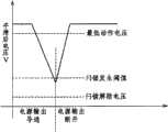
接着,对发生市电瞬时停电或瞬时电压降低的情况进行说明。首先,为了与本发明进行对比,对以往的例子进行说明。图4是表示以往的电源输出变化的时序图。在由FET对开关变压器的初级进行开关的电源电路中,当发生市电瞬时停电或瞬时电压降低时,具有使朝向负载(LED)提供规定电能的输入电流、即流过FET的电流增加的特性,从而成为与过载状态相同的状态。因此,当由于某种原因发生市电瞬时停电或瞬时电压降低时,虽然实际上不是由于LED等发生故障而导致的过载状态,但是流过开关元件的电流增加,造成过载保护功能动作,停止电源输出。即使在市电恢复正常之后,闩锁式过载保护功能也继续保持停止电源输出的状态。Next, a case where a commercial power momentary power failure or a momentary voltage drop occurs will be described. First, for comparison with the present invention, a conventional example will be described. FIG. 4 is a timing chart showing a conventional power supply output change. In a power supply circuit in which the primary side of a switching transformer is switched by a FET, when a momentary power failure or a momentary voltage drop occurs in the commercial power supply, it has the characteristic of increasing the input current that supplies the specified power to the load (LED), that is, the current flowing through the FET. , thus becoming the same state as the overload state. Therefore, when the commercial power momentary power failure or momentary voltage drop occurs for some reason, although it is not actually an overload state caused by a failure of the LED, etc., the current flowing through the switching element increases, causing the overload protection function to operate and stop the power supply. output. The latch-type overload protection function continues to stop the power supply output even after the mains power returns to normal.
在图4中,闩锁发生阈值是指当平滑后的电压V降低时,流过FET的电流增加,检测表面上看的过载状态时的电压值。此外,在图4中,最低动作电压是保证电源电路正常动作的电压,例如80V。此外,闩锁解除电压是用于解除闩锁的电压,例如20V~30V,通过暂时切断市电(关闭电源),可以对闩锁状态进行复位。In FIG. 4, the latch-up occurrence threshold is the voltage value at which the apparent overload state is detected by increasing the current flowing through the FET when the smoothed voltage V decreases. In addition, in FIG. 4 , the minimum operating voltage is a voltage that ensures normal operation of the power supply circuit, for example, 80V. In addition, the latch release voltage is a voltage for releasing the latch, for example, 20V to 30V, and the latched state can be reset by temporarily cutting off the commercial power (turning off the power supply).
例如,如图4所示,由于市电瞬时停电或瞬时电压降低,平滑后的电压V在短时间内(例如数十毫秒~数百毫秒)降低。当平滑后的电压V比闩锁发生阈值低时,过载保护功能动作,使FET的开关动作停止,电源输出从导通变为断开。此后,即使市电恢复正常,平滑后的电压V恢复到正常值(例如100V),由于仍然设置为闩锁状态,所以电源输出仍然断开,LED继续处于熄灭状态。For example, as shown in FIG. 4 , the smoothed voltage V drops within a short period of time (for example, tens of milliseconds to hundreds of milliseconds) due to instantaneous power failure or instantaneous voltage drop of the commercial power. When the smoothed voltage V is lower than the latch-up occurrence threshold, the overload protection function operates to stop the switching action of the FET, and the power output changes from on to off. Afterwards, even if the commercial power returns to normal and the smoothed voltage V returns to a normal value (for example, 100V), since it is still set to a latch state, the power supply output is still disconnected, and the LED continues to be in the off state.
接着,对本发明的情况进行说明。图5是表示本实施方式的电源部10的电源输出变化的一个例子的时序图。在图5中,低电压检测阈值Vth1是由电压检测部15的电阻153、154和齐纳二极管155设定的第一阈值Vth1(例如60V),设定成比上述的闩锁发生阈值大(高)的电压。Next, the case of the present invention will be described. FIG. 5 is a timing chart showing an example of changes in the power output of the
电压检测部15检测市电瞬时停电或瞬时电压降低的发生。并且,当电压检测部15检测出的电压V比第一阈值Vth1(例如60V等)低时,NPN晶体管158导通,控制端子Ve成为低电平(例如地电平),由此,过载保护电路部18使开关电路部17停止动作。The
然后,当市电恢复正常状态,使电压检测部15检测出的电压V比第一阈值Vth1高时,NPN晶体管158断开,控制端子Ve成为高电平,由此,过载保护电路部18解除开关电路部17的动作停止状态,使其再次开始动作。由此,也使电源输出恢复。Then, when the commercial power returns to a normal state and the voltage V detected by the
在这种情况下,当平滑电路部13输出的电压V降低时,流过FET171的电流增加,通过使第一阈值Vth1比作为由电阻181检测出过载状态时电压的闩锁发生阈值大,在由于市电瞬时停电或瞬时电压降低,使流过FET171的电流增加,由过载保护部182使FET171停止动作并保持停止状态之前,使FET171停止动作,并且使过载保护部182不动作。当市电恢复正常时,由于电压检测部15检测出的电压比第一阈值Vth1高,所以再次开始FET171的动作。由此,即使市电的电压波动时,也不发挥闩锁保护功能,从而可以正常地继续电源部10的动作。In this case, when the voltage V output from the smoothing
另外,电压检测部15的结构只是一个例子,并不限定于图3的例子。也可以设置PNP晶体管来代替NPN晶体管158。此外,也可以在控制端子Ve为高电平的情况下,过载保护电路部18使开关电路部17停止动作,在控制端子Ve为低电平的情况下,过载保护电路部18使开关电路部17再次开始动作。In addition, the configuration of the
此外,电压检测部15的结构并不限定于上述例子。图6是表示本实施方式的电源部10的电源输出变化的另一个例子的时序图。图6的例子中,在低电压检测阈值Vth1的基础上,还设置有比低电压检测阈值Vth1大(高)的低电压解除阈值Vth2(例如70V)。另外,为了在低电压检测阈值Vth1的基础上设定低电压解除阈值Vth2,在电压检测部15中追加了与电阻153、154、齐纳二极管155、NPN晶体管158相同的结构(电阻值等不同),并且通过组合“非”(反相)、“或”或“与”等逻辑运算来实现朝向两者的NPN晶体管的输出。In addition, the structure of the
电压检测部15检测市电瞬时停电或瞬时电压降低的发生。并且,当电压检测部15检测出的电压V比第一阈值Vth1(例如60V等)低时,控制端子Ve成为低电平(例如地电平),由此,过载保护电路部18使开关电路部17停止动作。The
此后,当市电恢复正常状态,使电压检测部15检测出的电压V比第一阈值Vth2高时,作为过载保护部182控制输入端的控制端子Ve成为高电平,由此,过载保护电路部18解除开关电路部17的动作停止状态,使其再次开始动作。由此,也使电源输出恢复。另外,在这种情况下,也可以设置低电压检测用端子和低电压解除用端子两个控制端子,而不是仅设置一个控制端子Ve。Thereafter, when the commercial power returns to a normal state and the voltage V detected by the
图7是表示由市电瞬时波动导致的平滑后电压的波动状况的示意图。如图7所示,当市电的瞬时电压波动在短时间内重复时,即使平滑后电压V在短时间内重复很小的波动,也可以通过在使FET171停止动作的第一阈值Vth1(低电压检测阈值)和使FET171再次开始动作的第二阈值Vth2(低电压解除阈值)之间具有所需要的电压宽度,来防止在短时间内使FET171重复停止、再次开始的动作,并且可以精确地检测出市电瞬时停电或瞬时电压降低。FIG. 7 is a schematic diagram showing fluctuations in voltage after smoothing caused by instantaneous fluctuations in commercial power. As shown in FIG. 7, when the instantaneous voltage fluctuation of the mains repeats in a short time, even if the smoothed voltage V repeats a small fluctuation in a short time, it can pass through the first threshold Vth1 (low voltage detection threshold) and the second threshold Vth2 (low voltage release threshold) that makes the FET171 start to operate again has the required voltage width to prevent the FET171 from repeatedly stopping and restarting in a short period of time, and can accurately Instantaneous power failure or instantaneous voltage drop of the mains is detected.
(实施方式2)(Embodiment 2)
图8是表示实施方式2的电源部10结构的一个例子的框图,图9是表示辅助电源控制部22的要部电路结构的一个例子的说明图。与实施方式1的不同点在于具有辅助电源控制部22。辅助电源控制部22用于监视从绝缘变压电路部16向调节部19提供的电压。当由市电瞬时停电或瞬时电压降低等导致绝缘变压电路部16的初级电压降低时,从绝缘变压电路部16提供的电压也降低。由此,向调节部19提供的电压降低,调节部19的输出电压也降低。并且,当提供给调节部19的电压比规定的第三阈值(例如,调节部19的输出电压降低至不能正常发挥恒定电流恒定电压电路部20功能的电压)低时,作为输出停止部的辅助电源控制部22使调节部19停止动作。8 is a block diagram showing an example of the configuration of the
在该状态下,当市电的电压恢复为正常值、从绝缘变压电路部16向调节部19提供的电压恢复到正常值时,由于调节部19的输出电压也恢复为正常值,恒定电流恒定电压电路部20正常启动,以恒定电流动作模式进行动作,所以可以提供例如LED所需要的电流,从而可以使LED以正常的亮度亮灯。In this state, when the voltage of the commercial power returns to a normal value and the voltage provided from the insulating
如图9所示,辅助电源控制部22包括输入电压稳压部221、电压比较部222、检测结果输出部223和电阻224等。此外,输入电压稳压部221具有齐纳二极管2211和电容器2212的串联电路,电压比较部222具有电阻2221、2222、2223、2224、2226、比较器2225和FET2227等,检测结果输出部223具有FET2231、2233、2234和电阻2232等。As shown in FIG. 9 , the auxiliary power
从绝缘变压电路部16向调节部19提供的电压利用输入电压稳压部221被稳压,并向电压比较部222输出。电压比较部222使稳压后的电压由电阻2221~2223进行分压,利用比较器2225对分压后的输入电压与电阻2224、2226所设定的基准电压进行比较,当输入电压在基准电压以下时,驱动检测结果输出部223,通过控制端子Vc使调节部19的动作开始/停止。例如,通过使控制端子Vc为低电平(地电平),来使调节部19停止动作,通过使控制端子Vc为高电平,使调节部19开始动作。如果从绝缘变压电路部16提供的电压恢复为正常值,则电压比较部222使检测结果输出部223的FET2234断开,通过电阻224向控制端子Vc施加规定的电压(高电平),来使调节部19开始动作。The voltage supplied from the isolation
图10是表示恒定电流恒定电压电路部20的输出特性的一个例子的说明图。在图10中,横轴表示电流,纵轴表示电压。如图10所示,一般来说,具有恒定电流输出方式的作为恒定电流控制部的恒定电流恒定电压电路部20相对于容许范围内的输出电压的波动,以恒定电流动作模式动作,可以输出恒定电流,并且当输出电压增加而超过容许范围时,从恒定电流动作模式转变成相对于输出电流的波动使输出电压恒定的恒定电压动作模式。FIG. 10 is an explanatory diagram showing an example of output characteristics of the constant current constant
当恒定电流恒定电压电路部20开始动作时,以恒定电流动作模式动作,例如相对于电压的波动进行电流控制,以使输出电流Iout恒定(参照图10中的实线箭头)。但是,当输出电压增加而超过容许范围时,如图10中的虚线箭头所示,从恒定电流动作模式转变成相对于输出电流的波动使输出电压Vout恒定的恒定电压动作模式。并且,当由于市电瞬时停电或瞬时电压降低使提供给恒定电流恒定电压电路部20的电压降低时,在恒定电流恒定电压电路部20内生成的基准电压也降低,从表面上看成为与输出电压(负载的电压)增加的状态相同的状态,恒定电流恒定电压电路部20从恒定电流动作模式转变成恒定电压动作模式。在该状态下,即使市电恢复正常,由于恒定电流恒定电压电路部20继续以恒定电压动作模式动作(例如图10中点P的状态),所以电源部10只能提供比LED所需要的电流Iout小的电流Ip,LED以比正常亮度暗的状态继续亮灯。When the constant current constant
通过设置辅助电源控制部22,当发生市电瞬时停电或瞬时电压降低,使提供给调节部19的电压比第三阈值低时,使调节部19停止动作。由此,可以防止恒定电流恒定电压电路部20从恒定电流动作模式转变成恒定电压动作模式。并且,在市电恢复正常的情况下,当向调节部19提供的电压比第三阈值大时,通过使暂时停止动作的恒定电流恒定电压电路部20再次开始动作,由于恒定电流恒定电压电路部20正常启动,以恒定电流动作模式动作,所以可以提供例如LED所需要的电流,从而可以使LED以正常的亮度亮灯。By providing the auxiliary power
图11是表示实施方式2的电源部10结构的另一个例子的框图。在图11的例子中,辅助电源控制部22不是用于控制调节部19,而是直接控制恒定电流恒定电压电路部20动作的停止/开始。即,当由辅助电源控制部22检测出从绝缘变压电路部16向调节部19提供的电压降低时,直接使恒定电流恒定电压电路部20停止动作,仅当从绝缘变压电路部16向调节部19提供的电压在规定电压以上时,使恒定电流恒定电压电路部20动作,这种方法也能够可靠地使LED亮灯。FIG. 11 is a block diagram showing another example of the configuration of the
如上所述,按照本发明,即使当发生市电瞬时停电或瞬时电压降低时,也可以防止因闩锁式过载保护电路部动作而使电源输出断开,从而可以继续正常动作。此外,当市电瞬时电压波动在短时间内重复时,可以防止开关元件在短时间内重复停止、再次开始的动作,并且可以高精度地检测出市电瞬时停电或瞬时电压降低。此外,即使当发生市电瞬时停电或瞬时电压降低时,也可以向LED提供所需要的电流,从而可以使LED以正常的亮度亮灯。此外,可以提供一种即使市电的电压波动时也可以正常地继续动作的照明装置。As described above, according to the present invention, even when a commercial power momentary power failure or a momentary voltage drop occurs, it is possible to prevent the power supply output from being disconnected due to the operation of the latch type overload protection circuit, and to continue normal operation. In addition, when the instantaneous voltage fluctuation of the commercial power is repeated in a short time, the switching element can be prevented from repeatedly stopping and restarting in a short time, and the instantaneous power failure or voltage drop of the commercial power can be detected with high precision. In addition, even when a momentary power failure or momentary voltage drop occurs in the commercial power supply, the required current can be supplied to the LED, so that the LED can be turned on with normal brightness. In addition, it is possible to provide a lighting device that can continue to operate normally even when the voltage of commercial power fluctuates.
在上述的实施方式中,虽然对把LED用作光源的例子进行了说明,但只要是能够以直流进行驱动的光源,则并不限定于LED,也可以将本发明应用于其他光源。In the above-mentioned embodiments, an example in which an LED is used as a light source has been described, but as long as it is a light source that can be driven by direct current, it is not limited to an LED, and the present invention can also be applied to other light sources.
在上述的实施方式中,虽然将来自市电的交流转换成直流,并且平滑电路部输出的电压正常时为100V,但是电压并不限定于此,也可以是200V或其他电压。在这种情况下,只要根据正常时的平滑后电压,适当地设定闩锁解除电压、低电压检测阈值和低电压解除阈值等即可。In the above embodiment, the AC from the commercial power is converted into DC, and the voltage output from the smoothing circuit unit is normally 100V, but the voltage is not limited thereto, and may be 200V or other voltages. In this case, the latch release voltage, the low voltage detection threshold, the low voltage release threshold, and the like may be appropriately set according to the normal smoothed voltage.
在上述的实施方式中,虽然以将本发明的电源装置用于照明装置为例进行了说明,但是并不限定于照明装置,只要是具有闩锁式过载保护功能的电子设备都可以应用本发明的电源装置。在这种情况下,即使发生市电瞬时停电或瞬时电压降低,也可以使电子设备继续进行正常动作。In the above-mentioned embodiments, although the power supply device of the present invention is used in the lighting device as an example, it is not limited to the lighting device, and the present invention can be applied to any electronic device that has a latch-type overload protection function. power supply unit. In this case, even if a momentary power failure or a momentary voltage drop occurs in the commercial power, the electronic device can continue to operate normally.
Claims (6)
Translated fromChineseApplications Claiming Priority (3)
| Application Number | Priority Date | Filing Date | Title |
|---|---|---|---|
| JP2008-222211 | 2008-08-29 | ||
| JP2008222211AJP5435912B2 (en) | 2008-08-29 | 2008-08-29 | Power supply device and lighting device |
| PCT/JP2009/003577WO2010023817A1 (en) | 2008-08-29 | 2009-07-29 | Power supply device and lighting device |
Publications (2)
| Publication Number | Publication Date |
|---|---|
| CN102132479Atrue CN102132479A (en) | 2011-07-20 |
| CN102132479B CN102132479B (en) | 2013-12-04 |
Family
ID=41721001
Family Applications (1)
| Application Number | Title | Priority Date | Filing Date |
|---|---|---|---|
| CN200980133130XAExpired - Fee RelatedCN102132479B (en) | 2008-08-29 | 2009-07-29 | Power supply device and lighting device |
Country Status (6)
| Country | Link |
|---|---|
| US (1) | US8508151B2 (en) |
| EP (1) | EP2325988A4 (en) |
| JP (1) | JP5435912B2 (en) |
| KR (1) | KR101276990B1 (en) |
| CN (1) | CN102132479B (en) |
| WO (1) | WO2010023817A1 (en) |
Cited By (7)
| Publication number | Priority date | Publication date | Assignee | Title |
|---|---|---|---|---|
| CN102916388A (en)* | 2011-08-04 | 2013-02-06 | 电子系统保护有限公司 | Supply voltage monitor |
| CN103220840A (en)* | 2012-01-20 | 2013-07-24 | 飞宏科技股份有限公司 | Power supply circuit for driving light emitting diode |
| CN104093238A (en)* | 2014-06-24 | 2014-10-08 | 苏州达方电子有限公司 | Power Converter with Reduced LED Drive Current at High Temperature |
| CN108599108A (en)* | 2018-04-30 | 2018-09-28 | 上海晶丰明源半导体股份有限公司 | Protect circuit, drive system, chip and circuit protection method, driving method |
| CN109246889A (en)* | 2018-09-26 | 2019-01-18 | 华域视觉科技(上海)有限公司 | The LED drive circuit and its driving method and storage medium of DC-DC and linear combination |
| CN109996364A (en)* | 2017-12-29 | 2019-07-09 | 群光电能科技股份有限公司 | Lighting device |
| CN111095765A (en)* | 2017-11-13 | 2020-05-01 | 欧姆龙株式会社 | Power supply system, method for displaying operating state of power supply device, and program |
Families Citing this family (41)
| Publication number | Priority date | Publication date | Assignee | Title |
|---|---|---|---|---|
| JP5364897B2 (en)* | 2008-10-03 | 2013-12-11 | 東芝ライテック株式会社 | Power supply device and lighting fixture |
| KR101677730B1 (en)* | 2009-08-14 | 2016-11-30 | 페어차일드코리아반도체 주식회사 | LED light emitting device |
| TW201115314A (en)* | 2009-10-30 | 2011-05-01 | De-Zheng Chen | Intelligent DC power supply circuit |
| DE102010031247A1 (en)* | 2010-03-19 | 2011-09-22 | Tridonic Ag | Low voltage power supply for a LED lighting system |
| KR101694998B1 (en)* | 2010-04-10 | 2017-01-10 | 엘지이노텍 주식회사 | Apparatus for led power control |
| JP5780812B2 (en) | 2010-05-12 | 2015-09-16 | キヤノン株式会社 | Voltage detection device and image heating device |
| JP2011254014A (en)* | 2010-06-03 | 2011-12-15 | On Semiconductor Trading Ltd | Luminous element control circuit |
| WO2011158282A1 (en)* | 2010-06-14 | 2011-12-22 | パナソニック株式会社 | Switching power supply apparatus, and semiconductor device for controlling thereof |
| JP5707564B2 (en)* | 2010-07-29 | 2015-04-30 | パナソニックIpマネジメント株式会社 | LED lighting device, lighting fixture including LED lighting device, and lighting system including LED lighting device |
| KR101164049B1 (en)* | 2010-08-12 | 2012-07-18 | 김한권 | The module of led dimming with cds sensor |
| JP5696289B2 (en)* | 2010-11-18 | 2015-04-08 | パナソニックIpマネジメント株式会社 | Converter circuit |
| JP2012119069A (en)* | 2010-11-29 | 2012-06-21 | Funai Electric Co Ltd | Led (light emitting diode) lighting circuit and liquid crystal display device |
| CN102754531B (en)* | 2010-12-02 | 2015-01-21 | 上舜照明(中国)有限公司 | LED driving power supply circuit, driving power supply and lighting device |
| KR101275399B1 (en)* | 2010-12-13 | 2013-06-17 | 삼성전기주식회사 | Light emitting diodes driver |
| US9204516B2 (en) | 2010-12-27 | 2015-12-01 | Panasonic Intellectual Property Management Co., Ltd. | Light-emitting diode driver circuit and LED light source |
| US9166396B2 (en) | 2011-01-31 | 2015-10-20 | Electronic Systems Protection, Inc. | Power conditioning, distribution and management |
| US10090662B2 (en) | 2011-01-31 | 2018-10-02 | Electronic Systems Protection, Inc. | Power monitoring and management with remote access |
| US8520349B2 (en) | 2011-01-31 | 2013-08-27 | Electronic Systems Protection, Inc. | Supply voltage monitor |
| KR101364124B1 (en)* | 2011-04-14 | 2014-02-20 | 삼상이엔지(주) | Apparatus of AC driving Light Emitting Diode and Method of Thereof |
| KR101216570B1 (en)* | 2011-06-07 | 2012-12-31 | 에코엘이디(주) | LED Lamp equipped with UPS |
| EP2546967B1 (en)* | 2011-07-15 | 2014-01-29 | OSRAM GmbH | A method for feeding light sources and related device |
| TWI424664B (en)* | 2011-08-24 | 2014-01-21 | Richtek Technology Corp | Power supply, controller thereof and control method thereof |
| JP5853190B2 (en)* | 2011-09-14 | 2016-02-09 | パナソニックIpマネジメント株式会社 | Solid state light emitting device driving device and lighting device |
| JP5873293B2 (en) | 2011-10-31 | 2016-03-01 | キヤノン株式会社 | Power supply device and image forming apparatus |
| TWI458390B (en)* | 2011-12-09 | 2014-10-21 | Gio Optoelectronics Corp | Light emitting apparatus |
| JP4975883B1 (en)* | 2011-12-22 | 2012-07-11 | パナソニック株式会社 | Light emitting diode drive circuit and LED light source |
| US9320100B2 (en) | 2013-03-11 | 2016-04-19 | Silicon Works Co., Ltd. | Lighting apparatus |
| JP6534086B2 (en)* | 2013-11-28 | 2019-06-26 | パナソニックIpマネジメント株式会社 | lighting equipment |
| KR101403861B1 (en)* | 2013-12-02 | 2014-06-09 | (주)에너브레인 | AC direct drive led power supply capable of handling overvoltage |
| US9723681B2 (en)* | 2014-08-21 | 2017-08-01 | Hsiao Chang Tsai | LED lamp system with different color temperatures and various operation modes |
| CN104578826B (en)* | 2014-12-31 | 2018-10-19 | 上海新进半导体制造有限公司 | Switching Power Supply and the method that constant pressure and current constant control are provided in Switching Power Supply |
| JP6531941B2 (en)* | 2015-07-08 | 2019-06-19 | パナソニックIpマネジメント株式会社 | Circuit device, lighting device, and vehicle using the same |
| JP2017153318A (en)* | 2016-02-26 | 2017-08-31 | サンケン電気株式会社 | Semiconductor apparatus for switching power supply |
| JP6685017B2 (en)* | 2016-07-19 | 2020-04-22 | パナソニックIpマネジメント株式会社 | Lighting device and lighting equipment |
| JP6796136B2 (en)* | 2016-08-30 | 2020-12-02 | ヌヴォトンテクノロジージャパン株式会社 | Switching power supply and semiconductor device |
| JP6854469B2 (en)* | 2017-02-24 | 2021-04-07 | パナソニックIpマネジメント株式会社 | Visible light communication device and visible light communication system |
| CN107018594B (en)* | 2017-04-07 | 2020-02-14 | 深圳迈睿智能科技有限公司 | LED load protection method |
| KR101890110B1 (en)* | 2017-10-26 | 2018-08-22 | 주식회사 신일라이팅 | Non-electrolytic power supply for LED |
| CN110418449A (en)* | 2018-04-27 | 2019-11-05 | 张淑铃 | Drive circuit device for automatically detecting line lights and optimizing drive voltage |
| WO2022176948A1 (en)* | 2021-02-19 | 2022-08-25 | パナソニックIpマネジメント株式会社 | Laser oscillator and direct diode laser processing apparatus provided with same |
| CN113595420A (en)* | 2021-09-06 | 2021-11-02 | 阳光电源股份有限公司 | Power converter and control method thereof |
Family Cites Families (13)
| Publication number | Priority date | Publication date | Assignee | Title |
|---|---|---|---|---|
| JPH04217877A (en) | 1990-12-19 | 1992-08-07 | Hitachi Seiko Ltd | Overcurrent protective device for inverter |
| JPH08234852A (en)* | 1995-02-27 | 1996-09-13 | Fuji Electric Co Ltd | Overload protection method for stabilized power supply |
| JPH11206116A (en) | 1998-01-19 | 1999-07-30 | Nagano Japan Radio Co | Constant voltage constant current power supply |
| JP2000295839A (en)* | 1999-04-06 | 2000-10-20 | Mitsubishi Electric Corp | Power supply |
| JP2002010474A (en)* | 2000-06-20 | 2002-01-11 | Fujitsu General Ltd | Power protection device |
| US6577512B2 (en)* | 2001-05-25 | 2003-06-10 | Koninklijke Philips Electronics N.V. | Power supply for LEDs |
| JP3578124B2 (en)* | 2001-08-31 | 2004-10-20 | ソニー株式会社 | Switching power supply |
| JP2005304128A (en)* | 2004-04-08 | 2005-10-27 | Matsushita Electric Ind Co Ltd | Power protection device |
| JP2007080771A (en) | 2005-09-16 | 2007-03-29 | Nec Lighting Ltd | Low voltage power supply circuit for lighting, lighting device, and low voltage power supply output method for lighting |
| JP4774904B2 (en)* | 2005-10-18 | 2011-09-21 | サンケン電気株式会社 | DC-DC converter |
| US7649327B2 (en)* | 2006-05-22 | 2010-01-19 | Permlight Products, Inc. | System and method for selectively dimming an LED |
| WO2008137460A2 (en)* | 2007-05-07 | 2008-11-13 | Koninklijke Philips Electronics N V | High power factor led-based lighting apparatus and methods |
| JP2008283798A (en)* | 2007-05-11 | 2008-11-20 | Matsushita Electric Ind Co Ltd | Switching control device |
- 2008
- 2008-08-29JPJP2008222211Apatent/JP5435912B2/ennot_activeExpired - Fee Related
- 2009
- 2009-07-29CNCN200980133130XApatent/CN102132479B/ennot_activeExpired - Fee Related
- 2009-07-29WOPCT/JP2009/003577patent/WO2010023817A1/enactiveApplication Filing
- 2009-07-29EPEP09809474.1Apatent/EP2325988A4/ennot_activeWithdrawn
- 2009-07-29USUS13/061,044patent/US8508151B2/ennot_activeExpired - Fee Related
- 2009-07-29KRKR1020117006856Apatent/KR101276990B1/ennot_activeExpired - Fee Related
Cited By (12)
| Publication number | Priority date | Publication date | Assignee | Title |
|---|---|---|---|---|
| CN102916388A (en)* | 2011-08-04 | 2013-02-06 | 电子系统保护有限公司 | Supply voltage monitor |
| CN102916388B (en)* | 2011-08-04 | 2017-04-12 | 电子系统保护有限公司 | Supply voltage monitor |
| CN103220840A (en)* | 2012-01-20 | 2013-07-24 | 飞宏科技股份有限公司 | Power supply circuit for driving light emitting diode |
| CN104093238A (en)* | 2014-06-24 | 2014-10-08 | 苏州达方电子有限公司 | Power Converter with Reduced LED Drive Current at High Temperature |
| CN104093238B (en)* | 2014-06-24 | 2016-05-11 | 苏州达方电子有限公司 | In the time of high temperature, can reduce the power supply changeover device of light emitting diode drive current |
| CN111095765A (en)* | 2017-11-13 | 2020-05-01 | 欧姆龙株式会社 | Power supply system, method for displaying operating state of power supply device, and program |
| CN111095765B (en)* | 2017-11-13 | 2023-07-07 | 欧姆龙株式会社 | Power supply system, method for displaying operation state of power supply device, and recording medium |
| CN109996364A (en)* | 2017-12-29 | 2019-07-09 | 群光电能科技股份有限公司 | Lighting device |
| CN108599108A (en)* | 2018-04-30 | 2018-09-28 | 上海晶丰明源半导体股份有限公司 | Protect circuit, drive system, chip and circuit protection method, driving method |
| CN108599108B (en)* | 2018-04-30 | 2023-11-17 | 上海晶丰明源半导体股份有限公司 | Protection circuit, driving system, chip, circuit protection method and driving method |
| CN109246889A (en)* | 2018-09-26 | 2019-01-18 | 华域视觉科技(上海)有限公司 | The LED drive circuit and its driving method and storage medium of DC-DC and linear combination |
| CN109246889B (en)* | 2018-09-26 | 2024-03-05 | 华域视觉科技(上海)有限公司 | DC-DC and linear combination LED driving circuit, driving method thereof and storage medium |
Also Published As
| Publication number | Publication date |
|---|---|
| JP2010057331A (en) | 2010-03-11 |
| KR20110048562A (en) | 2011-05-11 |
| JP5435912B2 (en) | 2014-03-05 |
| KR101276990B1 (en) | 2013-06-24 |
| EP2325988A1 (en) | 2011-05-25 |
| US8508151B2 (en) | 2013-08-13 |
| CN102132479B (en) | 2013-12-04 |
| WO2010023817A1 (en) | 2010-03-04 |
| US20110148319A1 (en) | 2011-06-23 |
| EP2325988A4 (en) | 2016-07-13 |
Similar Documents
| Publication | Publication Date | Title |
|---|---|---|
| CN102132479B (en) | Power supply device and lighting device | |
| US7301784B2 (en) | Lighting control unit for vehicle lighting fixture | |
| US9510411B2 (en) | Illumination device | |
| JP5052590B2 (en) | Power supply circuit and lighting device | |
| TWI388115B (en) | Power conversion drive circuit and lamp drive circuit | |
| US8680775B2 (en) | Lighting driver circuit and light fixture | |
| CN103124466B (en) | Lighting device and illumination apparatus | |
| JP4975083B2 (en) | Light source lighting device and lighting device | |
| US9277609B2 (en) | Back-up capacitor | |
| CN103687190B (en) | Solid-state light emitting element driving means, illuminator and ligthing paraphernalia | |
| TWI578843B (en) | Driving circuit of light-emitting diodes | |
| JP2009010100A (en) | Power supply device and lighting device | |
| CN107787606B (en) | LED lighting device | |
| US20180184490A1 (en) | Lighting device and luminaire | |
| KR20120080907A (en) | Light emitting diode emitting device | |
| JP2010056314A (en) | Driving circuit of light-emitting diode, light-emitting device using the same, and lighting device | |
| JP5671940B2 (en) | Lighting device and lighting fixture equipped with the lighting device | |
| US20110109237A1 (en) | Efficient power supply for solid state lighting system | |
| JP7027964B2 (en) | Lighting equipment, lighting fixtures and lighting systems | |
| CN112566313A (en) | Time-delay starting circuit and lamp | |
| TWI437918B (en) | Light device and power control circuit thereof | |
| CN102316638B (en) | LED lighting device and illumination fixture using the same | |
| CN108243527B (en) | Lighting device and lighting device | |
| JP7273356B2 (en) | Lighting device and lighting device | |
| JP2014229152A (en) | Load drive circuit having non-linear characteristic |
Legal Events
| Date | Code | Title | Description |
|---|---|---|---|
| C06 | Publication | ||
| PB01 | Publication | ||
| C10 | Entry into substantive examination | ||
| SE01 | Entry into force of request for substantive examination | ||
| C14 | Grant of patent or utility model | ||
| GR01 | Patent grant | ||
| CF01 | Termination of patent right due to non-payment of annual fee | ||
| CF01 | Termination of patent right due to non-payment of annual fee | Granted publication date:20131204 Termination date:20200729 |