CN102130698B - Echo detection and self-excitation elimination method for electromagnetic wave common-frequency amplifying repeater system - Google Patents
Echo detection and self-excitation elimination method for electromagnetic wave common-frequency amplifying repeater systemDownload PDFInfo
- Publication number
- CN102130698B CN102130698BCN201010042777.6ACN201010042777ACN102130698BCN 102130698 BCN102130698 BCN 102130698BCN 201010042777 ACN201010042777 ACN 201010042777ACN 102130698 BCN102130698 BCN 102130698B
- Authority
- CN
- China
- Prior art keywords
- amplifier
- phase
- echo
- electromagnetic wave
- gain
- Prior art date
- Legal status (The legal status is an assumption and is not a legal conclusion. Google has not performed a legal analysis and makes no representation as to the accuracy of the status listed.)
- Expired - Fee Related
Links
- 238000001514detection methodMethods0.000titleclaimsabstractdescription17
- 238000000034methodMethods0.000titleclaimsabstractdescription15
- 230000008030eliminationEffects0.000titleclaimsabstractdescription5
- 238000003379elimination reactionMethods0.000titleclaimsabstractdescription5
- 238000002955isolationMethods0.000claimsabstractdescription29
- 238000003199nucleic acid amplification methodMethods0.000claimsdescription5
- 230000003321amplificationEffects0.000claimsdescription4
- 238000004891communicationMethods0.000abstractdescription2
- 230000002159abnormal effectEffects0.000description3
- 230000005856abnormalityEffects0.000description3
- 238000006243chemical reactionMethods0.000description3
- 238000012360testing methodMethods0.000description3
- 230000008878couplingEffects0.000description2
- 238000010168coupling processMethods0.000description2
- 238000005859coupling reactionMethods0.000description2
- 230000007613environmental effectEffects0.000description2
- 230000032683agingEffects0.000description1
- 230000005540biological transmissionEffects0.000description1
- 238000010586diagramMethods0.000description1
- 238000009434installationMethods0.000description1
- 230000007774longtermEffects0.000description1
- 238000012544monitoring processMethods0.000description1
- 238000012545processingMethods0.000description1
- 230000009466transformationEffects0.000description1
Images


Classifications
- Y—GENERAL TAGGING OF NEW TECHNOLOGICAL DEVELOPMENTS; GENERAL TAGGING OF CROSS-SECTIONAL TECHNOLOGIES SPANNING OVER SEVERAL SECTIONS OF THE IPC; TECHNICAL SUBJECTS COVERED BY FORMER USPC CROSS-REFERENCE ART COLLECTIONS [XRACs] AND DIGESTS
- Y02—TECHNOLOGIES OR APPLICATIONS FOR MITIGATION OR ADAPTATION AGAINST CLIMATE CHANGE
- Y02D—CLIMATE CHANGE MITIGATION TECHNOLOGIES IN INFORMATION AND COMMUNICATION TECHNOLOGIES [ICT], I.E. INFORMATION AND COMMUNICATION TECHNOLOGIES AIMING AT THE REDUCTION OF THEIR OWN ENERGY USE
- Y02D30/00—Reducing energy consumption in communication networks
- Y02D30/70—Reducing energy consumption in communication networks in wireless communication networks
Landscapes
- Radio Relay Systems (AREA)
Abstract
Translated fromChinese
Description
Translated fromChinese技术领域technical field
本发明涉及一种电磁波信号同频放大直放站系统的返回电磁波(回波)检测和自激消除的方法。无线通信、数字电视、无线数据中继和其它无线电广播系统,距离发射基站较远区域,或由于地形等因素影响,需要对一些覆盖较差的区域进行信号增强,或需要增加覆盖范围,电磁波信号同频放大直放站装置是一种简单易行的低成本方案。其原理是把较小的信号接收放大后重新发射出去,这个系统中重发信号会有部分返回到接收天线,当直放站的放大增益大于接收天线重发天线之间的隔离时,回波会使直放站产生自激,使整个系统瘫痪。The invention relates to a method for detecting and self-excited elimination of returned electromagnetic waves (echo waves) in an electromagnetic wave signal co-frequency amplifying repeater system. For wireless communication, digital TV, wireless data relay and other radio broadcasting systems, in areas far away from the transmitting base station, or due to factors such as terrain, it is necessary to enhance the signal in some areas with poor coverage, or to increase the coverage, electromagnetic wave signal The same-frequency amplification repeater device is a simple and low-cost solution. The principle is to amplify the smaller signal and re-transmit it. In this system, part of the retransmitted signal will return to the receiving antenna. When the amplification gain of the repeater is greater than the isolation between the receiving antenna and the retransmitting antenna, the echo will Make the repeater self-excited and paralyze the whole system.
技术背景technical background
在实际应用中由于直放站的接收天线和重发天线物理距离很多情况不可能无限增大,两天线隔离不足时,回波产生自激,针对这种问题目前的解决方案是:In practical applications, the physical distance between the receiving antenna and the retransmitting antenna of the repeater cannot be infinitely increased in many cases. When the isolation between the two antennas is insufficient, the echo will generate self-excitation. The current solution to this problem is:
1、合理选点,尽量使用天然隔离架设收发天线和采用高定向天线增加接收天线和重发天线之间的隔离;专业技术人员测试隔离,并预留10-15DB隔离冗余调节增益。该方案工程费用高成本较高,对设备隔离度要求高,长期器件老化和环境变化引起的放大器增益变化或天线隔离度变化,会引起直放站功率下降或引发自激,隔离不足时只能减小增益,直放站放大器不能满功率发射。1. Reasonably select points, try to use natural isolation to set up transceiver antennas and use highly directional antennas to increase the isolation between receiving antennas and retransmitting antennas; professional and technical personnel test the isolation, and reserve 10-15DB isolation redundancy to adjust the gain. This solution has high engineering costs and high requirements for equipment isolation. Changes in amplifier gain or antenna isolation caused by long-term device aging and environmental changes will cause repeater power to drop or cause self-excitation. When isolation is insufficient, only Reduce the gain, the repeater amplifier cannot transmit at full power.
2、采用先下变频,数字基带对回波抵消再上变频的技术方案,该方案技术复杂,成本高,系统延时较大,抵消程度有限。隔离不足时还要减小增益,放大器也不能满功率发射。2. Adopt the technical scheme of down-conversion first, digital baseband to cancel the echo and then up-conversion. This scheme is technically complex, high in cost, and the system delay is large, and the degree of offset is limited. When the isolation is insufficient, the gain must be reduced, and the amplifier cannot transmit at full power.
发明内容Contents of the invention
针对以上方案存在问题,该发明发现了一种环境回波存在时的直放站放大器增益和回波信号到达接收天线相位与放大器输出功率三者之间关系,利用此关系曲线检测到回波大小,并根据曲线找到适合直放站放大器最大输出功率而不产生自激的回波相位,从而使直放站系统增益大为提高,有效地避免由于回波而引起的自激问题,降低了对收发天线隔离的要求,根据此关系,可以方便实现自动调节直放站系统,自适应环境,无需专业调试安装。In view of the problems in the above scheme, the invention discovers a relationship between the gain of the amplifier of the repeater station and the phase of the echo signal arriving at the receiving antenna and the output power of the amplifier when the environmental echo exists, and uses this relationship curve to detect the magnitude of the echo , and according to the curve to find the echo phase that is suitable for the maximum output power of the amplifier of the repeater without self-excitation, so that the system gain of the repeater is greatly improved, effectively avoiding the self-excitation problem caused by the echo, and reducing the impact on the According to the requirement of transceiver antenna isolation, according to this relationship, it is convenient to automatically adjust the repeater system and adapt to the environment without professional debugging and installation.
本发明核心是发现存在回波时,电磁波同频放大直放站系统中放大器的输出功率与放大器增益和重发射信号到达接收天线时的相位(回波相位)三者之间关系,根据此关系得到检测回波大小和消除放大器自激的方法。The core of the present invention is to find that when there is an echo, the relationship between the output power of the amplifier in the electromagnetic wave co-frequency amplifying repeater system, the gain of the amplifier and the phase (echo phase) when the retransmission signal arrives at the receiving antenna, according to this relationship A method of detecting the echo size and eliminating the self-excitation of the amplifier is obtained.
使用本发明的电磁波同频放大和直放站系统和传统方法比较,具有以下特点Using the electromagnetic wave same-frequency amplification and repeater system of the present invention compared with traditional methods, it has the following characteristics
1.可方便实现动态回波检测,自适应环境,动态调节系统参数。1. It is convenient to realize dynamic echo detection, adapt to the environment, and dynamically adjust system parameters.
2.对系统收发隔离极大降低,理论任意隔离均可以实现直放站放大器满功率发射。2. The isolation of the system's transceiver is greatly reduced, and theoretically any isolation can realize the full power transmission of the amplifier of the repeater.
3.射频无需进行下变频和数字基带处理,延时极小。3. The radio frequency does not need down-conversion and digital baseband processing, and the delay is extremely small.
4.与数字基带抵消回波方案的显著区别是:数字基带方案提高直放站系统增益是通过提高直放站放大器增益,增益大于收发隔离实现,本发明是利用调节回波相位,直放站放大器增益接近而不等于(小于不等于)隔离方式实现。4. The significant difference with the digital baseband echo cancellation scheme is: the digital baseband scheme improves the repeater system gain by increasing the repeater amplifier gain, and the gain is greater than the transceiver isolation. The present invention utilizes the adjustment of the echo phase, and the repeater The amplifier gain is close to but not equal to (less than or not equal to) isolation.
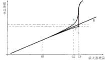
电磁波同频放大直放站系统存在回波,当接收天线与重发天线之间隔离小于等于直放站放大器增益时,直放站放大器产生自激。对直放站系统中放大器的输出功率与放大器增益和重发射信号到达接收天线时的相位(回波相位)测试,在隔离和空中信号强度保持不变时,调节直放站放大器输出信号相位,使放大器接收到回波信号相位发生变化,测试直放站放大器增益与输出功率关系,得出附图2曲线,图中曲线B是无回波时的直放站放大器输出功率与增益关系曲线,当直放站放大器增益远小于收发天线隔离时,图2中G1点一下位置,放大器输出功率与回波相位变化没有关系,增加直放站放大器增益,增益接近收发天线隔离,G3是增益等于隔离点,放大器的输出功率与无回波时的曲线B比较,回波相位与接收信号同相的A曲线输出功率渐渐变大,回波相位与接收信号反相的C曲线渐渐偏小,靠近G3点,图1所示,A曲线功率接近放大器满功率,C曲线接近无回波B曲线的-3dB点;到达增益等于隔离的临界点G3点时,A曲线到达放大器非线性区域,C曲线在B曲线-3dB功率位置急剧增大、直放站放大器自激进入放大器非线性区域。其它相位与功率关系在曲线A、C之间,图中未出现。图1是自激附近局部图,图中G2点是增益小于隔离3dB位置,A曲线功率高于B曲线功率3dB。There is an echo in the repeater system of electromagnetic wave co-amplification at the same frequency. When the isolation between the receiving antenna and the retransmitting antenna is less than or equal to the gain of the repeater amplifier, the repeater amplifier will generate self-excitation. Test the output power and amplifier gain of the amplifier in the repeater system and the phase (echo phase) when the retransmitted signal reaches the receiving antenna. When the isolation and air signal strength remain unchanged, adjust the output signal phase of the repeater amplifier. The phase of the echo signal received by the amplifier changes, and the relationship between the amplifier gain and the output power of the repeater is tested, and the curve in Figure 2 is obtained. Curve B in the figure is the relationship between the output power and the gain of the repeater amplifier when there is no echo. When the amplifier gain of the repeater is much smaller than the isolation of the transceiver antenna, click the position of G1 in Figure 2, the output power of the amplifier has nothing to do with the phase change of the echo, increase the gain of the amplifier of the repeater, the gain is close to the isolation of the transceiver antenna, G3 is the gain equal to the isolation point , the output power of the amplifier is compared with the curve B when there is no echo, the output power of the curve A whose echo phase is in phase with the received signal gradually increases, and the output power of the curve C whose echo phase is opposite to the received signal gradually becomes smaller, approaching the G3 point, As shown in Figure 1, the power of the A curve is close to the full power of the amplifier, and the C curve is close to the -3dB point of the no-echo B curve; when the gain is equal to the critical point G3 of isolation, the A curve reaches the nonlinear region of the amplifier, and the C curve is in the B curve The -3dB power position increases sharply, and the repeater amplifier self-excites into the nonlinear region of the amplifier. Other phase and power relationships are between curves A and C, which do not appear in the figure. Figure 1 is a local diagram near the self-excitation. Point G2 in the figure is the position where the gain is less than 3dB of isolation, and the power of curve A is 3dB higher than the power of curve B.
根据此组基本曲线,可以得到回波的检测方法和消除自激的基本方法,后面简要说明。According to this group of basic curves, the detection method of echo and the basic method of eliminating self-excitation can be obtained, which will be briefly explained later.
附图说明Description of drawings
图1本发明发现的在空中信号和隔离度不变时的直放站放大器增益、回波相位与输出功率局部曲线Repeater amplifier gain, echo phase and output power local curves when the air signal and isolation degree found by Fig. 1 the present invention are constant
图2本发明发现的在空中信号和隔离度不变时的直放站放大器增益、回波相位与输出功率完整曲线曲线The repeater amplifier gain, echo phase and output power complete curve curve when Fig. 2 present invention finds that air signal and isolation are constant
图3相位检测回波方案;Figure 3 phase detection echo scheme;
图4开关检测回波方案;Figure 4 switch detection echo scheme;
图5输入信号回波监测方案;Figure 5 input signal echo monitoring scheme;
图6数学变换后的在空中信号和隔离度不变时的直放站放大器增益、回波相位与放大器输入信号功率关系曲线。Figure 6 shows the relational curves of repeater amplifier gain, echo phase and amplifier input signal power after mathematical transformation when the air signal and isolation are constant.
具体实施方式Detailed ways
1.相位检测方法1. Phase detection method
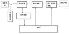
图3所示:接收天线接收到信号,经过可调节增益的放大器放大,进入相位调节电路,之后信号经过耦合器耦合部分信号进行功率检测,耦合器输出信号经过发射天线发射出去,功率检测信号进入MCU,MCU控制相位和放大器增益。As shown in Figure 3: The signal received by the receiving antenna is amplified by an amplifier with adjustable gain and enters the phase adjustment circuit. After that, the signal is coupled by a coupler for power detection. The output signal of the coupler is transmitted through the transmitting antenna, and the power detection signal enters MCU, MCU controls phase and amplifier gain.
方法一,开启放大器增益调至最小,缓慢增加放大器增益同时快速180度调节相位,放大器在A和C曲线之间工作,记录在A曲线和C曲线功率,到达G2点时,相位调节时发现输出功率变化到大于3dB,说明距自激点有3dB,定位功率最高点的相位,继续缓慢增大发射增益,使功率达到期望值,侦测功率是否异常。如有异常,回到G2点侦测重复上述,后面根据情况可以自行安排程序。如在增大增益过程中,输出功率急剧变大,说明到非A曲线到达G3点,重新相位调节。Method 1: Turn on the amplifier gain and adjust it to the minimum, slowly increase the amplifier gain and adjust the phase quickly 180 degrees, the amplifier works between the A and C curves, record the power in the A curve and C curve, when it reaches the G2 point, the output is found when the phase is adjusted If the power changes to more than 3dB, it means that there is 3dB away from the self-excitation point. Locate the phase of the highest power point, continue to increase the transmit gain slowly, so that the power reaches the expected value, and detect whether the power is abnormal. If there is any abnormality, go back to G2 point to detect and repeat the above, and then you can arrange the procedure by yourself according to the situation. If the output power increases sharply in the process of increasing the gain, it means that the non-A curve reaches point G3, and the phase adjustment should be re-adjusted.
方法二:开启放大器增益调至最小,缓慢增加放大器增益同时快速180度调节相位,放大器在A和C曲线之间工作,到G2点后,定位C曲线后继续增加增益,测试G3点位置,到G3点后,回退适量增益(1dB左右),调节相位至功率最大,转到A曲线,如超过功率期望值继续调低增益至期望功率,侦测功率是否异常。如有异常,回到G2点重复上述,后面根据情况可以自行安排程序。Method 2: Turn on the amplifier gain and adjust it to the minimum, slowly increase the amplifier gain and at the same time quickly adjust the phase by 180 degrees. The amplifier works between the A and C curves. After reaching the G2 point, continue to increase the gain after positioning the C curve, and test the position of the G3 point. After point G3, back off the appropriate amount of gain (about 1dB), adjust the phase to the maximum power, turn to the A curve, if the power exceeds the expected value, continue to reduce the gain to the expected power, and check whether the power is abnormal. If there is any abnormality, go back to point G2 and repeat the above, and then you can arrange the procedure by yourself according to the situation.
此方案对低频段和相对较窄频带和小功率系统最为适应。This scheme is most suitable for low frequency band and relatively narrow frequency band and low power system.
2.开关检测方法2. Switch detection method
图4所示,在图3的耦合器输出和天线之间串入一个天线开关,开关的另一边接50欧姆电阻到地。As shown in Figure 4, an antenna switch is connected in series between the output of the coupler in Figure 3 and the antenna, and the other side of the switch is connected to a 50-ohm resistor to ground.
开启放大器增益调至最小,缓慢增加放大器增益,同时180度调节输出相位,天线开关在关断和打开之间轮流切换,放大器工作在A-B、C-B曲线之间,记录A、B、C曲线功率,到G2点附近时,在功率C曲线停止相位调节,继续调大增益,功率突变大时说明到达G3点,回退适当功率一般1DB左右,置停止调节增益,调节相位至A曲线停止。侦测功率是否异常,如有异常,回到G2重复上述,后面根据情况,自行安排程序。Turn on the amplifier gain and adjust it to the minimum, slowly increase the amplifier gain, and at the same time adjust the output phase 180 degrees, switch the antenna switch between off and on in turn, the amplifier works between the A-B and C-B curves, record the power of the A, B, and C curves, When near point G2, stop phase adjustment on the power C curve, and continue to increase the gain. When the power suddenly changes, it means that you have reached point G3. The appropriate power back is generally about 1DB. Set it to stop adjusting the gain, and adjust the phase until the A curve stops. Detect whether the power is abnormal, if there is any abnormality, return to G2 and repeat the above, and then arrange the procedure by yourself according to the situation.
此方案对高频段、相对宽频带和大功率系统最为适应。This scheme is most suitable for high frequency band, relatively wide frequency band and high power system.
3.动态检测方法3. Dynamic detection method
对于运动使用环境和经常变化的使用环境,空间隔离随时变化,要实时调节放大器增益,上述方案要么瞬时自激,要么瞬时关闭信号,对重发信号瞬时损坏,不改变上述硬件结构,图4天线开关不需关闭到地,调节相位,放大器工作在A、C两曲线间,在G2附近设置门限,检测功率变化大于门限时减小增益,小于门限时增加功率。从而实现了不发生自激的连续调节。For sports use environment and frequently changing use environment, the space isolation changes at any time, and the amplifier gain must be adjusted in real time. The above scheme is either instantaneously self-excited, or instantaneously turns off the signal, and the retransmission signal is instantaneously damaged, without changing the above hardware structure. Figure 4 Antenna The switch does not need to be closed to the ground, adjust the phase, the amplifier works between the two curves A and C, set the threshold near G2, reduce the gain when the detected power change is greater than the threshold, and increase the power when it is less than the threshold. Thus, continuous regulation without self-excitation is realized.
4.输入信号回波检测方法4. Input signal echo detection method
图5所示,取消了放大器输出的耦合电路和功率检测电路,接收信号耦合一部分放大后用于输入信号功率检测,检测到的输入信号与输出相位和增益关系如图6所示,图6中G1、G2、G3与图2和图3对应的各个点相同。用此曲线对回波检测和自激消除方法和上述类似。As shown in Figure 5, the coupling circuit and power detection circuit of the amplifier output are canceled, and a part of the received signal coupling is amplified for input signal power detection. The relationship between the detected input signal and output phase and gain is shown in Figure 6. In Figure 6 G1, G2, and G3 are the same as the corresponding points in Fig. 2 and Fig. 3 . Use this curve for echo detection and self-excitation cancellation methods similar to the above.
Claims (2)
Translated fromChinesePriority Applications (1)
| Application Number | Priority Date | Filing Date | Title |
|---|---|---|---|
| CN201010042777.6ACN102130698B (en) | 2010-01-15 | 2010-01-15 | Echo detection and self-excitation elimination method for electromagnetic wave common-frequency amplifying repeater system |
Applications Claiming Priority (1)
| Application Number | Priority Date | Filing Date | Title |
|---|---|---|---|
| CN201010042777.6ACN102130698B (en) | 2010-01-15 | 2010-01-15 | Echo detection and self-excitation elimination method for electromagnetic wave common-frequency amplifying repeater system |
Publications (2)
| Publication Number | Publication Date |
|---|---|
| CN102130698A CN102130698A (en) | 2011-07-20 |
| CN102130698Btrue CN102130698B (en) | 2014-04-16 |
Family
ID=44268602
Family Applications (1)
| Application Number | Title | Priority Date | Filing Date |
|---|---|---|---|
| CN201010042777.6AExpired - Fee RelatedCN102130698B (en) | 2010-01-15 | 2010-01-15 | Echo detection and self-excitation elimination method for electromagnetic wave common-frequency amplifying repeater system |
Country Status (1)
| Country | Link |
|---|---|
| CN (1) | CN102130698B (en) |
Families Citing this family (160)
| Publication number | Priority date | Publication date | Assignee | Title |
|---|---|---|---|---|
| CN102792742B (en)* | 2011-10-31 | 2016-05-25 | 苏州全波通信技术有限公司 | The self-adaptation control method of repeater output signal and device thereof and system |
| US9113347B2 (en) | 2012-12-05 | 2015-08-18 | At&T Intellectual Property I, Lp | Backhaul link for distributed antenna system |
| US10009065B2 (en) | 2012-12-05 | 2018-06-26 | At&T Intellectual Property I, L.P. | Backhaul link for distributed antenna system |
| US9999038B2 (en) | 2013-05-31 | 2018-06-12 | At&T Intellectual Property I, L.P. | Remote distributed antenna system |
| US9525524B2 (en) | 2013-05-31 | 2016-12-20 | At&T Intellectual Property I, L.P. | Remote distributed antenna system |
| US8897697B1 (en) | 2013-11-06 | 2014-11-25 | At&T Intellectual Property I, Lp | Millimeter-wave surface-wave communications |
| US9209902B2 (en) | 2013-12-10 | 2015-12-08 | At&T Intellectual Property I, L.P. | Quasi-optical coupler |
| US9692101B2 (en) | 2014-08-26 | 2017-06-27 | At&T Intellectual Property I, L.P. | Guided wave couplers for coupling electromagnetic waves between a waveguide surface and a surface of a wire |
| US9768833B2 (en) | 2014-09-15 | 2017-09-19 | At&T Intellectual Property I, L.P. | Method and apparatus for sensing a condition in a transmission medium of electromagnetic waves |
| US10063280B2 (en) | 2014-09-17 | 2018-08-28 | At&T Intellectual Property I, L.P. | Monitoring and mitigating conditions in a communication network |
| US9628854B2 (en) | 2014-09-29 | 2017-04-18 | At&T Intellectual Property I, L.P. | Method and apparatus for distributing content in a communication network |
| US9615269B2 (en) | 2014-10-02 | 2017-04-04 | At&T Intellectual Property I, L.P. | Method and apparatus that provides fault tolerance in a communication network |
| US9685992B2 (en) | 2014-10-03 | 2017-06-20 | At&T Intellectual Property I, L.P. | Circuit panel network and methods thereof |
| US9503189B2 (en) | 2014-10-10 | 2016-11-22 | At&T Intellectual Property I, L.P. | Method and apparatus for arranging communication sessions in a communication system |
| US9973299B2 (en) | 2014-10-14 | 2018-05-15 | At&T Intellectual Property I, L.P. | Method and apparatus for adjusting a mode of communication in a communication network |
| US9762289B2 (en) | 2014-10-14 | 2017-09-12 | At&T Intellectual Property I, L.P. | Method and apparatus for transmitting or receiving signals in a transportation system |
| US9769020B2 (en) | 2014-10-21 | 2017-09-19 | At&T Intellectual Property I, L.P. | Method and apparatus for responding to events affecting communications in a communication network |
| US9780834B2 (en) | 2014-10-21 | 2017-10-03 | At&T Intellectual Property I, L.P. | Method and apparatus for transmitting electromagnetic waves |
| US9520945B2 (en) | 2014-10-21 | 2016-12-13 | At&T Intellectual Property I, L.P. | Apparatus for providing communication services and methods thereof |
| US9312919B1 (en) | 2014-10-21 | 2016-04-12 | At&T Intellectual Property I, Lp | Transmission device with impairment compensation and methods for use therewith |
| US9577306B2 (en) | 2014-10-21 | 2017-02-21 | At&T Intellectual Property I, L.P. | Guided-wave transmission device and methods for use therewith |
| US9653770B2 (en) | 2014-10-21 | 2017-05-16 | At&T Intellectual Property I, L.P. | Guided wave coupler, coupling module and methods for use therewith |
| US9627768B2 (en) | 2014-10-21 | 2017-04-18 | At&T Intellectual Property I, L.P. | Guided-wave transmission device with non-fundamental mode propagation and methods for use therewith |
| US9564947B2 (en) | 2014-10-21 | 2017-02-07 | At&T Intellectual Property I, L.P. | Guided-wave transmission device with diversity and methods for use therewith |
| US10340573B2 (en) | 2016-10-26 | 2019-07-02 | At&T Intellectual Property I, L.P. | Launcher with cylindrical coupling device and methods for use therewith |
| US9654173B2 (en) | 2014-11-20 | 2017-05-16 | At&T Intellectual Property I, L.P. | Apparatus for powering a communication device and methods thereof |
| US10009067B2 (en) | 2014-12-04 | 2018-06-26 | At&T Intellectual Property I, L.P. | Method and apparatus for configuring a communication interface |
| US9997819B2 (en) | 2015-06-09 | 2018-06-12 | At&T Intellectual Property I, L.P. | Transmission medium and method for facilitating propagation of electromagnetic waves via a core |
| US9461706B1 (en) | 2015-07-31 | 2016-10-04 | At&T Intellectual Property I, Lp | Method and apparatus for exchanging communication signals |
| US9680670B2 (en) | 2014-11-20 | 2017-06-13 | At&T Intellectual Property I, L.P. | Transmission device with channel equalization and control and methods for use therewith |
| US9800327B2 (en) | 2014-11-20 | 2017-10-24 | At&T Intellectual Property I, L.P. | Apparatus for controlling operations of a communication device and methods thereof |
| US9954287B2 (en) | 2014-11-20 | 2018-04-24 | At&T Intellectual Property I, L.P. | Apparatus for converting wireless signals and electromagnetic waves and methods thereof |
| US9544006B2 (en) | 2014-11-20 | 2017-01-10 | At&T Intellectual Property I, L.P. | Transmission device with mode division multiplexing and methods for use therewith |
| US9742462B2 (en) | 2014-12-04 | 2017-08-22 | At&T Intellectual Property I, L.P. | Transmission medium and communication interfaces and methods for use therewith |
| US10243784B2 (en) | 2014-11-20 | 2019-03-26 | At&T Intellectual Property I, L.P. | System for generating topology information and methods thereof |
| US10144036B2 (en) | 2015-01-30 | 2018-12-04 | At&T Intellectual Property I, L.P. | Method and apparatus for mitigating interference affecting a propagation of electromagnetic waves guided by a transmission medium |
| US9876570B2 (en) | 2015-02-20 | 2018-01-23 | At&T Intellectual Property I, Lp | Guided-wave transmission device with non-fundamental mode propagation and methods for use therewith |
| US10224981B2 (en) | 2015-04-24 | 2019-03-05 | At&T Intellectual Property I, Lp | Passive electrical coupling device and methods for use therewith |
| US9705561B2 (en) | 2015-04-24 | 2017-07-11 | At&T Intellectual Property I, L.P. | Directional coupling device and methods for use therewith |
| US9793954B2 (en) | 2015-04-28 | 2017-10-17 | At&T Intellectual Property I, L.P. | Magnetic coupling device and methods for use therewith |
| US9948354B2 (en) | 2015-04-28 | 2018-04-17 | At&T Intellectual Property I, L.P. | Magnetic coupling device with reflective plate and methods for use therewith |
| US9490869B1 (en) | 2015-05-14 | 2016-11-08 | At&T Intellectual Property I, L.P. | Transmission medium having multiple cores and methods for use therewith |
| US9871282B2 (en) | 2015-05-14 | 2018-01-16 | At&T Intellectual Property I, L.P. | At least one transmission medium having a dielectric surface that is covered at least in part by a second dielectric |
| US10679767B2 (en) | 2015-05-15 | 2020-06-09 | At&T Intellectual Property I, L.P. | Transmission medium having a conductive material and methods for use therewith |
| US10650940B2 (en) | 2015-05-15 | 2020-05-12 | At&T Intellectual Property I, L.P. | Transmission medium having a conductive material and methods for use therewith |
| US9917341B2 (en) | 2015-05-27 | 2018-03-13 | At&T Intellectual Property I, L.P. | Apparatus and method for launching electromagnetic waves and for modifying radial dimensions of the propagating electromagnetic waves |
| US9912381B2 (en) | 2015-06-03 | 2018-03-06 | At&T Intellectual Property I, Lp | Network termination and methods for use therewith |
| US9866309B2 (en) | 2015-06-03 | 2018-01-09 | At&T Intellectual Property I, Lp | Host node device and methods for use therewith |
| US10154493B2 (en) | 2015-06-03 | 2018-12-11 | At&T Intellectual Property I, L.P. | Network termination and methods for use therewith |
| US10348391B2 (en) | 2015-06-03 | 2019-07-09 | At&T Intellectual Property I, L.P. | Client node device with frequency conversion and methods for use therewith |
| US10103801B2 (en) | 2015-06-03 | 2018-10-16 | At&T Intellectual Property I, L.P. | Host node device and methods for use therewith |
| US10812174B2 (en) | 2015-06-03 | 2020-10-20 | At&T Intellectual Property I, L.P. | Client node device and methods for use therewith |
| US9913139B2 (en) | 2015-06-09 | 2018-03-06 | At&T Intellectual Property I, L.P. | Signal fingerprinting for authentication of communicating devices |
| US10142086B2 (en) | 2015-06-11 | 2018-11-27 | At&T Intellectual Property I, L.P. | Repeater and methods for use therewith |
| US9608692B2 (en) | 2015-06-11 | 2017-03-28 | At&T Intellectual Property I, L.P. | Repeater and methods for use therewith |
| US9820146B2 (en) | 2015-06-12 | 2017-11-14 | At&T Intellectual Property I, L.P. | Method and apparatus for authentication and identity management of communicating devices |
| US9667317B2 (en) | 2015-06-15 | 2017-05-30 | At&T Intellectual Property I, L.P. | Method and apparatus for providing security using network traffic adjustments |
| US9640850B2 (en) | 2015-06-25 | 2017-05-02 | At&T Intellectual Property I, L.P. | Methods and apparatus for inducing a non-fundamental wave mode on a transmission medium |
| US9509415B1 (en) | 2015-06-25 | 2016-11-29 | At&T Intellectual Property I, L.P. | Methods and apparatus for inducing a fundamental wave mode on a transmission medium |
| US9865911B2 (en) | 2015-06-25 | 2018-01-09 | At&T Intellectual Property I, L.P. | Waveguide system for slot radiating first electromagnetic waves that are combined into a non-fundamental wave mode second electromagnetic wave on a transmission medium |
| US9722318B2 (en) | 2015-07-14 | 2017-08-01 | At&T Intellectual Property I, L.P. | Method and apparatus for coupling an antenna to a device |
| US10044409B2 (en) | 2015-07-14 | 2018-08-07 | At&T Intellectual Property I, L.P. | Transmission medium and methods for use therewith |
| US9836957B2 (en) | 2015-07-14 | 2017-12-05 | At&T Intellectual Property I, L.P. | Method and apparatus for communicating with premises equipment |
| US10148016B2 (en) | 2015-07-14 | 2018-12-04 | At&T Intellectual Property I, L.P. | Apparatus and methods for communicating utilizing an antenna array |
| US9853342B2 (en) | 2015-07-14 | 2017-12-26 | At&T Intellectual Property I, L.P. | Dielectric transmission medium connector and methods for use therewith |
| US10320586B2 (en) | 2015-07-14 | 2019-06-11 | At&T Intellectual Property I, L.P. | Apparatus and methods for generating non-interfering electromagnetic waves on an insulated transmission medium |
| US10341142B2 (en) | 2015-07-14 | 2019-07-02 | At&T Intellectual Property I, L.P. | Apparatus and methods for generating non-interfering electromagnetic waves on an uninsulated conductor |
| US9882257B2 (en) | 2015-07-14 | 2018-01-30 | At&T Intellectual Property I, L.P. | Method and apparatus for launching a wave mode that mitigates interference |
| US10170840B2 (en) | 2015-07-14 | 2019-01-01 | At&T Intellectual Property I, L.P. | Apparatus and methods for sending or receiving electromagnetic signals |
| US10033107B2 (en) | 2015-07-14 | 2018-07-24 | At&T Intellectual Property I, L.P. | Method and apparatus for coupling an antenna to a device |
| US9628116B2 (en) | 2015-07-14 | 2017-04-18 | At&T Intellectual Property I, L.P. | Apparatus and methods for transmitting wireless signals |
| US10033108B2 (en) | 2015-07-14 | 2018-07-24 | At&T Intellectual Property I, L.P. | Apparatus and methods for generating an electromagnetic wave having a wave mode that mitigates interference |
| US9847566B2 (en) | 2015-07-14 | 2017-12-19 | At&T Intellectual Property I, L.P. | Method and apparatus for adjusting a field of a signal to mitigate interference |
| US10205655B2 (en) | 2015-07-14 | 2019-02-12 | At&T Intellectual Property I, L.P. | Apparatus and methods for communicating utilizing an antenna array and multiple communication paths |
| US9793951B2 (en) | 2015-07-15 | 2017-10-17 | At&T Intellectual Property I, L.P. | Method and apparatus for launching a wave mode that mitigates interference |
| US10090606B2 (en) | 2015-07-15 | 2018-10-02 | At&T Intellectual Property I, L.P. | Antenna system with dielectric array and methods for use therewith |
| US9608740B2 (en) | 2015-07-15 | 2017-03-28 | At&T Intellectual Property I, L.P. | Method and apparatus for launching a wave mode that mitigates interference |
| US9871283B2 (en) | 2015-07-23 | 2018-01-16 | At&T Intellectual Property I, Lp | Transmission medium having a dielectric core comprised of plural members connected by a ball and socket configuration |
| US9912027B2 (en) | 2015-07-23 | 2018-03-06 | At&T Intellectual Property I, L.P. | Method and apparatus for exchanging communication signals |
| US10784670B2 (en) | 2015-07-23 | 2020-09-22 | At&T Intellectual Property I, L.P. | Antenna support for aligning an antenna |
| US9749053B2 (en) | 2015-07-23 | 2017-08-29 | At&T Intellectual Property I, L.P. | Node device, repeater and methods for use therewith |
| US9948333B2 (en) | 2015-07-23 | 2018-04-17 | At&T Intellectual Property I, L.P. | Method and apparatus for wireless communications to mitigate interference |
| US9735833B2 (en) | 2015-07-31 | 2017-08-15 | At&T Intellectual Property I, L.P. | Method and apparatus for communications management in a neighborhood network |
| US9967173B2 (en) | 2015-07-31 | 2018-05-08 | At&T Intellectual Property I, L.P. | Method and apparatus for authentication and identity management of communicating devices |
| US10020587B2 (en) | 2015-07-31 | 2018-07-10 | At&T Intellectual Property I, L.P. | Radial antenna and methods for use therewith |
| US9904535B2 (en) | 2015-09-14 | 2018-02-27 | At&T Intellectual Property I, L.P. | Method and apparatus for distributing software |
| US10009063B2 (en) | 2015-09-16 | 2018-06-26 | At&T Intellectual Property I, L.P. | Method and apparatus for use with a radio distributed antenna system having an out-of-band reference signal |
| US10009901B2 (en) | 2015-09-16 | 2018-06-26 | At&T Intellectual Property I, L.P. | Method, apparatus, and computer-readable storage medium for managing utilization of wireless resources between base stations |
| US10079661B2 (en) | 2015-09-16 | 2018-09-18 | At&T Intellectual Property I, L.P. | Method and apparatus for use with a radio distributed antenna system having a clock reference |
| US10051629B2 (en) | 2015-09-16 | 2018-08-14 | At&T Intellectual Property I, L.P. | Method and apparatus for use with a radio distributed antenna system having an in-band reference signal |
| US10136434B2 (en) | 2015-09-16 | 2018-11-20 | At&T Intellectual Property I, L.P. | Method and apparatus for use with a radio distributed antenna system having an ultra-wideband control channel |
| US9769128B2 (en) | 2015-09-28 | 2017-09-19 | At&T Intellectual Property I, L.P. | Method and apparatus for encryption of communications over a network |
| US9729197B2 (en) | 2015-10-01 | 2017-08-08 | At&T Intellectual Property I, L.P. | Method and apparatus for communicating network management traffic over a network |
| US10074890B2 (en) | 2015-10-02 | 2018-09-11 | At&T Intellectual Property I, L.P. | Communication device and antenna with integrated light assembly |
| US9882277B2 (en) | 2015-10-02 | 2018-01-30 | At&T Intellectual Property I, Lp | Communication device and antenna assembly with actuated gimbal mount |
| US9876264B2 (en) | 2015-10-02 | 2018-01-23 | At&T Intellectual Property I, Lp | Communication system, guided wave switch and methods for use therewith |
| US10051483B2 (en) | 2015-10-16 | 2018-08-14 | At&T Intellectual Property I, L.P. | Method and apparatus for directing wireless signals |
| US10355367B2 (en) | 2015-10-16 | 2019-07-16 | At&T Intellectual Property I, L.P. | Antenna structure for exchanging wireless signals |
| US10665942B2 (en) | 2015-10-16 | 2020-05-26 | At&T Intellectual Property I, L.P. | Method and apparatus for adjusting wireless communications |
| US9912419B1 (en) | 2016-08-24 | 2018-03-06 | At&T Intellectual Property I, L.P. | Method and apparatus for managing a fault in a distributed antenna system |
| US9860075B1 (en) | 2016-08-26 | 2018-01-02 | At&T Intellectual Property I, L.P. | Method and communication node for broadband distribution |
| US10291311B2 (en) | 2016-09-09 | 2019-05-14 | At&T Intellectual Property I, L.P. | Method and apparatus for mitigating a fault in a distributed antenna system |
| US11032819B2 (en) | 2016-09-15 | 2021-06-08 | At&T Intellectual Property I, L.P. | Method and apparatus for use with a radio distributed antenna system having a control channel reference signal |
| US10135146B2 (en) | 2016-10-18 | 2018-11-20 | At&T Intellectual Property I, L.P. | Apparatus and methods for launching guided waves via circuits |
| US10135147B2 (en) | 2016-10-18 | 2018-11-20 | At&T Intellectual Property I, L.P. | Apparatus and methods for launching guided waves via an antenna |
| US10340600B2 (en) | 2016-10-18 | 2019-07-02 | At&T Intellectual Property I, L.P. | Apparatus and methods for launching guided waves via plural waveguide systems |
| US9876605B1 (en) | 2016-10-21 | 2018-01-23 | At&T Intellectual Property I, L.P. | Launcher and coupling system to support desired guided wave mode |
| US9991580B2 (en) | 2016-10-21 | 2018-06-05 | At&T Intellectual Property I, L.P. | Launcher and coupling system for guided wave mode cancellation |
| US10374316B2 (en) | 2016-10-21 | 2019-08-06 | At&T Intellectual Property I, L.P. | System and dielectric antenna with non-uniform dielectric |
| US10811767B2 (en) | 2016-10-21 | 2020-10-20 | At&T Intellectual Property I, L.P. | System and dielectric antenna with convex dielectric radome |
| US10312567B2 (en) | 2016-10-26 | 2019-06-04 | At&T Intellectual Property I, L.P. | Launcher with planar strip antenna and methods for use therewith |
| US10498044B2 (en) | 2016-11-03 | 2019-12-03 | At&T Intellectual Property I, L.P. | Apparatus for configuring a surface of an antenna |
| US10291334B2 (en) | 2016-11-03 | 2019-05-14 | At&T Intellectual Property I, L.P. | System for detecting a fault in a communication system |
| US10225025B2 (en) | 2016-11-03 | 2019-03-05 | At&T Intellectual Property I, L.P. | Method and apparatus for detecting a fault in a communication system |
| US10224634B2 (en) | 2016-11-03 | 2019-03-05 | At&T Intellectual Property I, L.P. | Methods and apparatus for adjusting an operational characteristic of an antenna |
| US10340601B2 (en) | 2016-11-23 | 2019-07-02 | At&T Intellectual Property I, L.P. | Multi-antenna system and methods for use therewith |
| US10340603B2 (en) | 2016-11-23 | 2019-07-02 | At&T Intellectual Property I, L.P. | Antenna system having shielded structural configurations for assembly |
| US10535928B2 (en) | 2016-11-23 | 2020-01-14 | At&T Intellectual Property I, L.P. | Antenna system and methods for use therewith |
| US10178445B2 (en) | 2016-11-23 | 2019-01-08 | At&T Intellectual Property I, L.P. | Methods, devices, and systems for load balancing between a plurality of waveguides |
| US10090594B2 (en) | 2016-11-23 | 2018-10-02 | At&T Intellectual Property I, L.P. | Antenna system having structural configurations for assembly |
| US10361489B2 (en) | 2016-12-01 | 2019-07-23 | At&T Intellectual Property I, L.P. | Dielectric dish antenna system and methods for use therewith |
| US10305190B2 (en) | 2016-12-01 | 2019-05-28 | At&T Intellectual Property I, L.P. | Reflecting dielectric antenna system and methods for use therewith |
| US10694379B2 (en) | 2016-12-06 | 2020-06-23 | At&T Intellectual Property I, L.P. | Waveguide system with device-based authentication and methods for use therewith |
| US10326494B2 (en) | 2016-12-06 | 2019-06-18 | At&T Intellectual Property I, L.P. | Apparatus for measurement de-embedding and methods for use therewith |
| US10727599B2 (en) | 2016-12-06 | 2020-07-28 | At&T Intellectual Property I, L.P. | Launcher with slot antenna and methods for use therewith |
| US10755542B2 (en) | 2016-12-06 | 2020-08-25 | At&T Intellectual Property I, L.P. | Method and apparatus for surveillance via guided wave communication |
| US10819035B2 (en) | 2016-12-06 | 2020-10-27 | At&T Intellectual Property I, L.P. | Launcher with helical antenna and methods for use therewith |
| US9927517B1 (en) | 2016-12-06 | 2018-03-27 | At&T Intellectual Property I, L.P. | Apparatus and methods for sensing rainfall |
| US10135145B2 (en) | 2016-12-06 | 2018-11-20 | At&T Intellectual Property I, L.P. | Apparatus and methods for generating an electromagnetic wave along a transmission medium |
| US10020844B2 (en) | 2016-12-06 | 2018-07-10 | T&T Intellectual Property I, L.P. | Method and apparatus for broadcast communication via guided waves |
| US10439675B2 (en) | 2016-12-06 | 2019-10-08 | At&T Intellectual Property I, L.P. | Method and apparatus for repeating guided wave communication signals |
| US10637149B2 (en) | 2016-12-06 | 2020-04-28 | At&T Intellectual Property I, L.P. | Injection molded dielectric antenna and methods for use therewith |
| US10382976B2 (en) | 2016-12-06 | 2019-08-13 | At&T Intellectual Property I, L.P. | Method and apparatus for managing wireless communications based on communication paths and network device positions |
| US10027397B2 (en) | 2016-12-07 | 2018-07-17 | At&T Intellectual Property I, L.P. | Distributed antenna system and methods for use therewith |
| US10139820B2 (en) | 2016-12-07 | 2018-11-27 | At&T Intellectual Property I, L.P. | Method and apparatus for deploying equipment of a communication system |
| US10389029B2 (en) | 2016-12-07 | 2019-08-20 | At&T Intellectual Property I, L.P. | Multi-feed dielectric antenna system with core selection and methods for use therewith |
| US10446936B2 (en) | 2016-12-07 | 2019-10-15 | At&T Intellectual Property I, L.P. | Multi-feed dielectric antenna system and methods for use therewith |
| US9893795B1 (en) | 2016-12-07 | 2018-02-13 | At&T Intellectual Property I, Lp | Method and repeater for broadband distribution |
| US10359749B2 (en) | 2016-12-07 | 2019-07-23 | At&T Intellectual Property I, L.P. | Method and apparatus for utilities management via guided wave communication |
| US10168695B2 (en) | 2016-12-07 | 2019-01-01 | At&T Intellectual Property I, L.P. | Method and apparatus for controlling an unmanned aircraft |
| US10547348B2 (en) | 2016-12-07 | 2020-01-28 | At&T Intellectual Property I, L.P. | Method and apparatus for switching transmission mediums in a communication system |
| US10243270B2 (en) | 2016-12-07 | 2019-03-26 | At&T Intellectual Property I, L.P. | Beam adaptive multi-feed dielectric antenna system and methods for use therewith |
| US9911020B1 (en) | 2016-12-08 | 2018-03-06 | At&T Intellectual Property I, L.P. | Method and apparatus for tracking via a radio frequency identification device |
| US10916969B2 (en) | 2016-12-08 | 2021-02-09 | At&T Intellectual Property I, L.P. | Method and apparatus for providing power using an inductive coupling |
| US10601494B2 (en) | 2016-12-08 | 2020-03-24 | At&T Intellectual Property I, L.P. | Dual-band communication device and method for use therewith |
| US10103422B2 (en) | 2016-12-08 | 2018-10-16 | At&T Intellectual Property I, L.P. | Method and apparatus for mounting network devices |
| US9998870B1 (en) | 2016-12-08 | 2018-06-12 | At&T Intellectual Property I, L.P. | Method and apparatus for proximity sensing |
| US10530505B2 (en) | 2016-12-08 | 2020-01-07 | At&T Intellectual Property I, L.P. | Apparatus and methods for launching electromagnetic waves along a transmission medium |
| US10326689B2 (en) | 2016-12-08 | 2019-06-18 | At&T Intellectual Property I, L.P. | Method and system for providing alternative communication paths |
| US10069535B2 (en) | 2016-12-08 | 2018-09-04 | At&T Intellectual Property I, L.P. | Apparatus and methods for launching electromagnetic waves having a certain electric field structure |
| US10389037B2 (en) | 2016-12-08 | 2019-08-20 | At&T Intellectual Property I, L.P. | Apparatus and methods for selecting sections of an antenna array and use therewith |
| US10777873B2 (en) | 2016-12-08 | 2020-09-15 | At&T Intellectual Property I, L.P. | Method and apparatus for mounting network devices |
| US10938108B2 (en) | 2016-12-08 | 2021-03-02 | At&T Intellectual Property I, L.P. | Frequency selective multi-feed dielectric antenna system and methods for use therewith |
| US10411356B2 (en) | 2016-12-08 | 2019-09-10 | At&T Intellectual Property I, L.P. | Apparatus and methods for selectively targeting communication devices with an antenna array |
| US10340983B2 (en) | 2016-12-09 | 2019-07-02 | At&T Intellectual Property I, L.P. | Method and apparatus for surveying remote sites via guided wave communications |
| US9838896B1 (en) | 2016-12-09 | 2017-12-05 | At&T Intellectual Property I, L.P. | Method and apparatus for assessing network coverage |
| US10264586B2 (en) | 2016-12-09 | 2019-04-16 | At&T Mobility Ii Llc | Cloud-based packet controller and methods for use therewith |
| US9973940B1 (en) | 2017-02-27 | 2018-05-15 | At&T Intellectual Property I, L.P. | Apparatus and methods for dynamic impedance matching of a guided wave launcher |
| US10298293B2 (en) | 2017-03-13 | 2019-05-21 | At&T Intellectual Property I, L.P. | Apparatus of communication utilizing wireless network devices |
| CN111756461B (en) | 2020-07-23 | 2022-08-16 | 展讯通信(上海)有限公司 | Self-excitation detection method and system of wireless signal relay amplification device |
Citations (4)
| Publication number | Priority date | Publication date | Assignee | Title |
|---|---|---|---|---|
| WO2006114749A1 (en)* | 2005-04-28 | 2006-11-02 | Koninklijke Philips Electronics N.V. | Method and circuit arrangement for operating multi-channel transmit/receive antenna devices |
| CN1988412A (en)* | 2006-12-23 | 2007-06-27 | 桂林市思奇通信设备有限公司 | High frequency broad band friquency shift repeator |
| CN101483453A (en)* | 2008-04-16 | 2009-07-15 | 北京创毅视讯科技有限公司 | Echo cancellation device of mobile multimedia system repeater and echo cancellation method |
| CN101599791A (en)* | 2009-07-09 | 2009-12-09 | 上海贝电实业股份有限公司 | Method for automatically eliminating autoexcitation of wireless TD repeater |
- 2010
- 2010-01-15CNCN201010042777.6Apatent/CN102130698B/ennot_activeExpired - Fee Related
Patent Citations (4)
| Publication number | Priority date | Publication date | Assignee | Title |
|---|---|---|---|---|
| WO2006114749A1 (en)* | 2005-04-28 | 2006-11-02 | Koninklijke Philips Electronics N.V. | Method and circuit arrangement for operating multi-channel transmit/receive antenna devices |
| CN1988412A (en)* | 2006-12-23 | 2007-06-27 | 桂林市思奇通信设备有限公司 | High frequency broad band friquency shift repeator |
| CN101483453A (en)* | 2008-04-16 | 2009-07-15 | 北京创毅视讯科技有限公司 | Echo cancellation device of mobile multimedia system repeater and echo cancellation method |
| CN101599791A (en)* | 2009-07-09 | 2009-12-09 | 上海贝电实业股份有限公司 | Method for automatically eliminating autoexcitation of wireless TD repeater |
Also Published As
| Publication number | Publication date |
|---|---|
| CN102130698A (en) | 2011-07-20 |
Similar Documents
| Publication | Publication Date | Title |
|---|---|---|
| CN102130698B (en) | Echo detection and self-excitation elimination method for electromagnetic wave common-frequency amplifying repeater system | |
| CN105991096B (en) | Adjusting the Power Amplifier Excitation Based on the Output Signal | |
| US8244173B2 (en) | RF repeater | |
| KR20110071838A (en) | Relay apparatus and method in a wireless communication system | |
| US8447230B2 (en) | Variable gain antenna for cellular repeater | |
| CN105594121A (en) | Power amplifier with input power protection circuits | |
| CN202197283U (en) | Communication relay device and its standing wave ratio detection device | |
| WO2018191985A1 (en) | Radio frequency control system and control method | |
| CN112118055A (en) | Standing wave detection device and communication equipment | |
| CN100502490C (en) | Ground digital television repeater | |
| CN102904537B (en) | Weak wireless signal amplifier of time division duplex system and control method | |
| CN208143502U (en) | A kind of wireless access point device of high-power low-noise | |
| KR102361113B1 (en) | Passive feedback path for pre-distortion in power amplifiers | |
| CN103067066A (en) | Interference rejection method for down-chain of double-antenna satellite communication system | |
| CN201018504Y (en) | Ground digital television repeater | |
| CN103916176B (en) | A kind of wireless discharging-directly station and its antenna calibration method | |
| KR20150007016A (en) | Feedback circuit in wireless transmitter | |
| CN205249149U (en) | Airborne station power amplifier unit | |
| CN205986789U (en) | Two -way radio frequency amplifier input/output reverse -connection protective circuit | |
| EP3748868B1 (en) | Digital repeater system | |
| KR101756807B1 (en) | Apparatus and method for controlling transmission power in a wireless communication system | |
| WO2021188792A1 (en) | Single-chip digital pre-distortion (dpd) device implemented using radio frequency transceiver integrated circuit with integrated dpd function | |
| CN116419383B (en) | Automatic gain control method, circuit and equipment | |
| KR101201195B1 (en) | Apparatus for relay using Time Division Duplexing application | |
| CN207588857U (en) | For the signal amplifying apparatus of train-installed wireless telecom equipment |
Legal Events
| Date | Code | Title | Description |
|---|---|---|---|
| C06 | Publication | ||
| PB01 | Publication | ||
| C10 | Entry into substantive examination | ||
| SE01 | Entry into force of request for substantive examination | ||
| C14 | Grant of patent or utility model | ||
| GR01 | Patent grant | ||
| DD01 | Delivery of document by public notice | Addressee:Zhao Xiaolin Document name:Notification to Pay the Fees | |
| TR01 | Transfer of patent right | Effective date of registration:20200622 Address after:518000 Guangdong city of Shenzhen province Baoan District Fuyong Street Huaide Chui Industrial Park District No. 41A building 4 floor Patentee after:Shenzhen Jiaxian communication equipment Co.,Ltd. Address before:518000, No. 10, No. 708, Taoyuan village, Dragon Pearl Road, Shenzhen, Guangdong, Nanshan District Patentee before:Zhao Xiaolin | |
| TR01 | Transfer of patent right | ||
| DD01 | Delivery of document by public notice | ||
| DD01 | Delivery of document by public notice | Addressee:Zhao Xiaolin Document name:Notice of conformity | |
| CP03 | Change of name, title or address | ||
| CP03 | Change of name, title or address | Address after:518000 Room 101, building C4, Zone C, Fuhai international science and Technology Park, Zhancheng community, Fuhai street, Bao'an District, Shenzhen, Guangdong Province Patentee after:Shenzhen Jiaxian Communication Technology Co.,Ltd. Address before:518000 4th floor, building 41a, area 5, Cuigang Industrial Park, Huaide, Fuyong street, Bao'an District, Shenzhen City, Guangdong Province Patentee before:Shenzhen Jiaxian communication equipment Co.,Ltd. | |
| CF01 | Termination of patent right due to non-payment of annual fee | ||
| CF01 | Termination of patent right due to non-payment of annual fee | Granted publication date:20140416 |