CN102119072B - A method and a system for facilitating calibration of an off-line programmed robot cell - Google Patents
A method and a system for facilitating calibration of an off-line programmed robot cellDownload PDFInfo
- Publication number
- CN102119072B CN102119072BCN200880129169.XACN200880129169ACN102119072BCN 102119072 BCN102119072 BCN 102119072BCN 200880129169 ACN200880129169 ACN 200880129169ACN 102119072 BCN102119072 BCN 102119072B
- Authority
- CN
- China
- Prior art keywords
- robot
- calibration
- calibration point
- sequence
- image
- Prior art date
- Legal status (The legal status is an assumption and is not a legal conclusion. Google has not performed a legal analysis and makes no representation as to the accuracy of the status listed.)
- Active
Links
- 238000000034methodMethods0.000titleclaimsabstractdescription70
- 238000012546transferMethods0.000claimsabstractdescription5
- 238000004088simulationMethods0.000description8
- 238000004891communicationMethods0.000description7
- 238000004519manufacturing processMethods0.000description3
- 238000004364calculation methodMethods0.000description2
- 238000011960computer-aided designMethods0.000description2
- 238000010586diagramMethods0.000description2
- 230000003213activating effectEffects0.000description1
- 238000004590computer programMethods0.000description1
- 238000007796conventional methodMethods0.000description1
- 238000012937correctionMethods0.000description1
- 230000001934delayEffects0.000description1
- 238000011161developmentMethods0.000description1
- 230000018109developmental processEffects0.000description1
- 230000000694effectsEffects0.000description1
- 230000006870functionEffects0.000description1
- 230000000977initiatory effectEffects0.000description1
- 230000003993interactionEffects0.000description1
Images


Classifications
- B—PERFORMING OPERATIONS; TRANSPORTING
- B25—HAND TOOLS; PORTABLE POWER-DRIVEN TOOLS; MANIPULATORS
- B25J—MANIPULATORS; CHAMBERS PROVIDED WITH MANIPULATION DEVICES
- B25J9/00—Programme-controlled manipulators
- B25J9/16—Programme controls
- B25J9/1679—Programme controls characterised by the tasks executed
- B25J9/1692—Calibration of manipulator
- B—PERFORMING OPERATIONS; TRANSPORTING
- B25—HAND TOOLS; PORTABLE POWER-DRIVEN TOOLS; MANIPULATORS
- B25J—MANIPULATORS; CHAMBERS PROVIDED WITH MANIPULATION DEVICES
- B25J9/00—Programme-controlled manipulators
- B25J9/16—Programme controls
- B25J9/1656—Programme controls characterised by programming, planning systems for manipulators
- B25J9/1671—Programme controls characterised by programming, planning systems for manipulators characterised by simulation, either to verify existing program or to create and verify new program, CAD/CAM oriented, graphic oriented programming systems
- G—PHYSICS
- G05—CONTROLLING; REGULATING
- G05B—CONTROL OR REGULATING SYSTEMS IN GENERAL; FUNCTIONAL ELEMENTS OF SUCH SYSTEMS; MONITORING OR TESTING ARRANGEMENTS FOR SUCH SYSTEMS OR ELEMENTS
- G05B2219/00—Program-control systems
- G05B2219/30—Nc systems
- G05B2219/36—Nc in input of data, input key till input tape
- G05B2219/36404—Adapt teached position as function of deviation 3-D, 2-D position workpiece
- G—PHYSICS
- G05—CONTROLLING; REGULATING
- G05B—CONTROL OR REGULATING SYSTEMS IN GENERAL; FUNCTIONAL ELEMENTS OF SUCH SYSTEMS; MONITORING OR TESTING ARRANGEMENTS FOR SUCH SYSTEMS OR ELEMENTS
- G05B2219/00—Program-control systems
- G05B2219/30—Nc systems
- G05B2219/39—Robotics, robotics to robotics hand
- G05B2219/39021—With probe, touch reference positions
- G—PHYSICS
- G05—CONTROLLING; REGULATING
- G05B—CONTROL OR REGULATING SYSTEMS IN GENERAL; FUNCTIONAL ELEMENTS OF SUCH SYSTEMS; MONITORING OR TESTING ARRANGEMENTS FOR SUCH SYSTEMS OR ELEMENTS
- G05B2219/00—Program-control systems
- G05B2219/30—Nc systems
- G05B2219/40—Robotics, robotics mapping to robotics vision
- G05B2219/40099—Graphical user interface for robotics, visual robot user interface
Landscapes
- Engineering & Computer Science (AREA)
- Robotics (AREA)
- Mechanical Engineering (AREA)
- Manipulator (AREA)
- Numerical Control (AREA)
Abstract
Translated fromChinese
Description
Translated fromChinese技术领域technical field
本发明涉及有助于对机器人单元进行校准的方法和系统,机器人单元包括一个或多个目标物以及进行与目标物有关的工作的工业机器人,其中通过离线编程工具对机器人单元进行编程。The present invention relates to a method and system for facilitating the calibration of a robotic cell comprising one or more objects and an industrial robot performing work related to the object, wherein the robotic cell is programmed by means of an offline programming tool.
本发明涉及如下情形下从离线到在线编程的领域:用户在三维或二维离线环境中已经对机器人程序进行了编程和调整,然后希望在工厂车间采用该程序。The invention relates to the field of offline to online programming in situations where a user has programmed and adjusted a robot program in a 3D or 2D offline environment and then wishes to adopt this program on the factory floor.
背景技术Background technique
工业机器人是在许多不同的工业应用中用于各种各样操作的高度灵活的设备。工业机器人通常经由与惯用的计算机编程语言非常相似的机器人编程语言来进行编程。机器人程序包括程序指令的序列,其中每个指令告诉机器人控制单元该做什么和如何做。机器人被编程为遵循包括多个目标点的路径。机器人程序包括目标点的位置。机器人的编程是个耗时的过程,且在编程和示教过程期间使用机器人的惯用方法阻碍了生产设备并使投产推迟。为了节约时间和加速投产,非常期望对机器人进行离线编程。通常,这是由离线编程工具通过图形模拟来完成的。编程工具包含图形部件,图形部件用于基于机器人和目标物的图形模型例如计算机辅助设计(CAD)模型来生成机器人单元中的机器人和目标物(例如工作目标物和工具)的图形三维表示。编程工具还包含用于示教目标点和路径并且记录机器人的操作和移动的图形装置。图形模拟为对工业机器人进行编程和可视化提供了更多自然而简单的方法,而不会牵制实际设备。此外,图形环境允许独立于机器人制造商使用的机器人编程语言。通过模拟输出的是在操作期间机器人该做什么和真实的机器人程序的图形表示。当完成模拟和离线编程时,程序可以被转移到真实的机器人。Industrial robots are highly flexible devices used in a wide variety of operations in many different industrial applications. Industrial robots are usually programmed via a robotics programming language very similar to customary computer programming languages. A robot program consists of a sequence of program instructions, where each instruction tells the robot control unit what to do and how to do it. The robot is programmed to follow a path that includes multiple goal points. The robot program includes the location of the target point. Programming a robot is a time-consuming process, and the conventional method of using a robot during the programming and teaching process hinders production equipment and delays launch. To save time and speed up production, it is highly desirable to program robots offline. Typically, this is done through graphical simulation by offline programming tools. The programming tool includes graphical components for generating graphical three-dimensional representations of the robot and objects (eg, work objects and tools) in the robotic cell based on graphical models of the robot and objects, such as computer-aided design (CAD) models. The programming tool also contains graphical means for teaching target points and paths, and recording robot operations and movements. Graphical simulations provide more natural and easy ways to program and visualize industrial robots without tying down the actual equipment. Furthermore, the graphical environment allows independence from the robot programming language used by the robot manufacturer. Output from the simulation is a graphical representation of what the robot should do during operation and the actual robot program. When the simulation and offline programming are done, the program can be transferred to the real robot.
然而,由离线编程系统准备的机器人程序不能直接用于在真实的机器人单元中操作机器人,因为离线环境中的机器人和目标物之间的位置关系可以偏离真实的机器人单元中的机器人和目标物之间的实际位置关系。传统上这是一个非常困难的问题并且已经成为在工业上采用离线编程的障碍。However, the robot program prepared by the offline programming system cannot be directly used to operate the robot in the real robot cell, because the positional relationship between the robot and the object in the offline environment can deviate from that between the robot and the object in the real robot cell. the actual positional relationship between them. This is traditionally a very difficult problem and has been an obstacle to the adoption of offline programming in industry.
因此,在基于目标物的图形模型生成机器人程序后,必须确定真实目标物相对于机器人的位置。目标物可以是机器人单元中的任何类型的目标物,如工件、工作站、工具、机器人底座、或外部设备。通常编程的路径中的实际目标位置与关于目标物定义的参考系有关,这表示对目标物进行校准将调整关于公共坐标系的相关的目标位置。机器人单元的校准包括关于公共坐标系确定机器人单元中的机器人和目标物的位置。这典型地是通过使用机器人作为测量设备来完成的。用户轻推机器人到目标物上的至少三个校准点,且对于校准点记录机器人位置。术语“轻推机器人”是指机器人由用户手动移动,例如依靠操纵杆。然后记录的机器人位置用于确定机器人和真实目标物之间的关系。由于机器人和目标物的模型之间的关系是已知的,所以可以确定目标物的模型和真实位置之间的关系。然后可以更新目标物的真实位置,并且由于保持了编程的路径上的位置和目标物之间的关系,因此将更新在编程的路径上的所有位置。Therefore, after generating the robot program based on the graphical model of the object, it is necessary to determine the position of the real object relative to the robot. An object can be any type of object in a robotic cell, such as a workpiece, workstation, tool, robot base, or external equipment. Usually the actual target position in the programmed path is related to a frame of reference defined with respect to the target, which means that calibrating the target will adjust the relative target position with respect to the common coordinate system. Calibration of the robotic cell includes determining the positions of the robot and the object in the robotic cell with respect to a common coordinate system. This is typically done using a robot as the measuring device. The user jogs the robot to at least three calibration points on the object, and the robot position is recorded for the calibration points. The term "nudge robot" means that the robot is moved manually by the user, for example by means of a joystick. The recorded robot position is then used to determine the relationship between the robot and the real object. Since the relationship between the robot and the model of the object is known, the relationship between the model of the object and the true position of the object can be determined. The real position of the target can then be updated, and since the relationship between the positions on the programmed path and the target is maintained, all positions on the programmed path will be updated.
控制机器人的人被称作机器人操作员。在下文中,单词用户和机器人操作员作同义使用。当有许多目标物将要被校准的时候,用户必须轻推机器人到所有的目标物并且因此到目标物上的许多校准点。此外,机器人访问校准点的顺序对于校准结果是重要的。典型地,用户必须在一张纸上写下所有要被校准的目标物和校准点的位置。这花费时间并且容易出错。The person who controls the robot is called the robot operator. In the following, the words user and robot operator are used synonymously. When there are many targets to be calibrated, the user has to jog the robot to all the targets and thus to many calibration points on the target. Furthermore, the order in which the robot visits the calibration points is important for the calibration results. Typically, the user must write down all the targets to be calibrated and the locations of the calibration points on a piece of paper. This takes time and is error prone.
校准后,模型和单元中的真实目标物之间仍然会有偏差。在将机器人程序应用到生产之前,必须检查和校正机器人程序,例如为了避免碰撞。这表示离线生成的机器人程序必须在机器人上运行。EP1510894公开了用于校正离线生成的机器人程序的设备。该设备包括用于在接收到停止命令时停止机器人程序的执行的装置、用于在执行停止时在显示屏上显示其位置要被校正的下一个目标点的装置、用于通过从程序的执行已经被停止的位置轻推来移动机器人的装置、和用于当校正了目标点的位置时将机器人的当前位置反映到其位置将要被校正的下一个目标点上的装置。必须对编程的路径上的每个目标点重复校正过程,这很耗时。After calibration, there will still be a bias between the model and the real objects in the cell. Robot programs must be checked and corrected before they are used in production, for example to avoid collisions. This means that robot programs generated offline must be run on the robot. EP1510894 discloses a device for correcting robot programs generated offline. The device comprises means for stopping the execution of the robot program when a stop command is received, means for displaying on a display screen the next target point whose position is to be corrected when the execution stops, Means for moving the robot by jogging at a position that has been stopped, and means for reflecting the current position of the robot to the next target point whose position is to be corrected when the position of the target point is corrected. The correction process must be repeated for each target point on the programmed path, which is time consuming.
发明内容Contents of the invention
本发明的目的是为机器人操作员提供有助于校准机器人单元中的目标物的工具。It is an object of the present invention to provide a robot operator with tools that help to calibrate objects in a robot cell.
根据本发明的一个方面,通过如权利要求1中限定的方法来实现这个目的。According to an aspect of the invention, this object is achieved by a method as defined in
这种方法包括:为目标物中的每个目标物存储校准点的序列,自动生成图像的序列,图像包括要被校准的目标物和关于目标物的校准点的图形表示,将图像的序列转移到机器人,以及在校准机器人单元期间将图像的所述序列显示给机器人操作员,使得对于每个校准点将包括当前校准点和要被校准的目标物的视图显示给机器人操作员。The method includes storing a sequence of calibration points for each of the objects, automatically generating a sequence of images including the object to be calibrated and a graphical representation of the calibration points with respect to the object, transferring the sequence of images to to the robot, and during calibration of the robotic cell said sequence of images is displayed to the robot operator such that for each calibration point a view comprising the current calibration point and the object to be calibrated is displayed to the robot operator.
对于每个目标物,在离线环境中存储一组预定的校准点和关于在校准期间校准点将被访问的理想顺序的信息。根据本发明,生成了包括要被校准的目标物和关于目标物的校准点的图形表示的多个图像。该图像是包括图形目标物的虚拟图像。图像的序列示出校准点要被机器人访问的顺序。在校准期间这些图像被转移到机器人并显示给用户。校准点被优选地选择使得可以从图像容易地识别它们的位置,例如在目标物的角处、或在如尖端的突出部分处。图像有助于机器人操作员将机器人移动到校准点。For each target, a predetermined set of calibration points and information about the desired order in which the calibration points will be visited during calibration is stored in an off-line environment. According to the invention, a plurality of images comprising a graphical representation of the object to be calibrated and calibration points on the object are generated. The image is a virtual image including a graphical object. The sequence of images shows the order in which the calibration points are to be visited by the robot. These images are transferred to the robot and displayed to the user during calibration. The calibration points are preferably chosen such that their position can be easily identified from the image, for example at the corners of the object, or at protruding parts like tips. The images help the robot operator to move the robot to the calibration point.
本发明提供了帮助机器人操作员将离线编程的机器人程序拿到工厂车间(factory floor)的机器人单元并校准机器人单元中的目标物的系统和方法。本发明加速了校准处理并降低了与校准有关的错误的风险,这样的错误使得操作员将机器人移动到错误的校准点。The present invention provides systems and methods to assist robot operators in bringing robot programs programmed off-line to robot cells on the factory floor and calibrating objects in the robot cells. The invention speeds up the calibration process and reduces the risk of calibration related errors causing an operator to move the robot to the wrong calibration point.
根据本发明的实施例,通过从图像库加载真实图像来生成图像。According to an embodiment of the present invention, images are generated by loading real images from an image library.
根据本发明的另一个实施例,使用与用于对机器人进行编程相同的图形部件来生成图像。例如,图像是来自编程期间进行的机器人单元的模拟的屏幕截图(或者快照)。这个实施例使得产生图像变得容易。According to another embodiment of the invention, the image is generated using the same graphics components used to program the robot. For example, the image is a screenshot (or snapshot) from a simulation of the robotic cell performed during programming. This embodiment makes it easy to generate images.
根据本发明的实施例,将校准点的序列与目标物的图形模型一起存储。离线编程工具包括目标物的多个图形模型。根据本发明的这个实施例,图形模型中的每个图像模型设置有预定义的校准点的序列。程序员通过选择一个或多个目标物模型并将它们添加到单元,来建立虚拟机器人单元。因此,将要使用哪个校准点取决于程序员选择哪个目标物。这个实施例使得在校准期间提供要使用的校准点变得容易。According to an embodiment of the invention, the sequence of calibration points is stored together with the graphical model of the object. Offline programming tools include multiple graphical models of objects. According to this embodiment of the invention, each image model in the graphical model is provided with a predefined sequence of calibration points. Programmers build virtual robotic cells by selecting one or more object models and adding them to the cell. Therefore, which calibration point will be used depends on which target the programmer chooses. This embodiment makes it easy to provide calibration points to use during calibration.
根据本发明的实施例,方法包括:基于所述存储的校准点的序列自动生成至少一个校准程序,校准程序包括用于将机器人移动到校准点处的位置或接近校准点的位置的指令;将校准程序和图像转移到机器人;以及执行所述校准程序使得对于每个校准点,机器人自动移动到校准点处的位置或者接近校准点处的位置。在离线环境自动生成包括用于将机器人移动到校准点处的位置或者接近校准点处的位置的指令的校准程序。将校准程序转移到机器人并且在校准期间使用校准程序以将机器人快速移动到校准点或接近校准点。尽管机器人被编程为移动到校准点,实际上由于在离线环境中机器人和目标物之间的位置关系偏离机器人和目标物之间的实际位置关系的事实,机器人不会准确地移动到校准点。因此,机器人操作员必须手动移动机器人到目标物上的准确的校准点。在校准期间显示给用户的图像有助于操作员轻推机器人到正确的校准点。这个实施例进一步有助于对机器人单元的校准。According to an embodiment of the invention, the method comprises: automatically generating at least one calibration program based on said stored sequence of calibration points, the calibration program comprising instructions for moving the robot to a position at or close to the calibration point; transferring the calibration procedure and images to the robot; and executing the calibration procedure such that for each calibration point, the robot automatically moves to a location at or near the calibration point. A calibration program including instructions for moving the robot to a location at or near a location at the calibration point is automatically generated in an offline environment. The calibration program is transferred to the robot and used during calibration to quickly move the robot to or near the calibration point. Although the robot is programmed to move to the calibration point, in practice the robot does not move to the calibration point accurately due to the fact that the positional relationship between the robot and the object deviates from the actual positional relationship between the robot and the object in an offline environment. Therefore, the robot operator must manually move the robot to the exact calibration point on the target. Images shown to the user during calibration help the operator nudge the robot to the correct calibration point. This embodiment further facilitates the calibration of the robotic cell.
根据本发明的实施例,方法包括:基于所述校准点的序列自动生成步进式用户界面,步进式用户界面示出图像并引导用户通过校准过程,将用户界面转移到机器人,以及在校准期间显示用户界面。根据本发明的这个实施例,来自离线编程工具的图像与步进式用户界面相结合,步进式用户界面例如在示教器单元上呈现图像,并且逐步地引导用户通过校准过程。According to an embodiment of the invention, the method comprises: automatically generating a step-by-step user interface based on said sequence of calibration points, the step-by-step user interface showing images and guiding the user through the calibration process, transferring the user interface to the robot, and The user interface is displayed during this time. According to this embodiment of the invention, the images from the offline programming tool are combined with a step-by-step user interface that presents images, eg on a teach pendant unit, and guides the user step-by-step through the calibration process.
根据本发明的实施例,机器人包括控制单元和用于手动控制机器人的具有显示装置的示教器单元(TPU),所述校准程序被转移到控制单元并由控制单元执行,所述图像在示教器单元的显示装置上显示。According to an embodiment of the present invention, the robot comprises a control unit and a teach pendant unit (TPU) with a display device for manually controlling the robot, the calibration procedure is transferred to and executed by the control unit, the image is displayed on the display displayed on the display unit of the teaching unit.
根据本发明的实施例,方法包括:当机器人被定位在校准点时,对于校准点中的每个校准点存储机器人的位置;以及对于机器人单元中的每个目标物,基于对于校准点存储的机器人的位置,确定目标物的模型和真实目标物之间的位置关系。According to an embodiment of the present invention, the method includes: when the robot is positioned at the calibration point, for each of the calibration points, storing the position of the robot; and for each object in the robot cell, based on the The position of the robot determines the positional relationship between the model of the target and the real target.
根据本发明的实施例,所述图像中的每个图像示出来自校准程序的、关于机器人移动到序列中的下一个校准点的信息,所述图像的每个图像示出用于启动和停止校准程序的执行的用户激活装置。这个实施例使得用户可以对于每个校准点确定是否要运行校准程序。According to an embodiment of the invention, each of said images shows information from a calibration procedure about the movement of the robot to the next calibration point in the sequence, each of said images shows a function for starting and stopping User-activated device for execution of the calibration procedure. This embodiment allows the user to determine for each calibration point whether to run the calibration procedure.
根据本发明的实施例,每个校准点设置有示出要被校准的目标物和根据校准点的序列、机器人将要被移动到的下一个校准点的图像。为了提供机器人单元的精确校准,机器人以定义的顺序访问校准点是重要的。通过将下一个校准的位置显示给操作员,确保了操作员以正确的校准点序列将机器人移动到正确的校准点。According to an embodiment of the invention, each calibration point is provided with an image showing the object to be calibrated and the next calibration point to which the robot is to be moved according to the sequence of calibration points. In order to provide accurate calibration of the robotic cell, it is important that the robot visits the calibration points in a defined order. By displaying the position of the next calibration to the operator, it is ensured that the operator moves the robot to the correct calibration point in the correct sequence of calibration points.
根据本发明的实施例,关于目标物中的每个目标物来定义参考系并且通过所述离线编程工具对包括关于参考系定义的多个目标点的路径进行编程,该方法包括:对于校准点中的每个校准点,存储当机器人被定位在校准点时的机器人的位置;以及对于每个目标物,基于对于校准点存储的机器人的位置来确定目标物的模型的参考系和真实目标物的参考系之间的位置关系。参考系是相对目标物固定的坐标系。参考系的位置和方向由目标物的位置和方向来确定。如果坐标系中有多于一个目标物,则参考系针对每个目标物来定义。参考系是在公共世界坐标系中定义的。这个实施例消除了校正路径上的编程的位置的必要。所有需要的是校正目标物的参考系的位置和方向,由此将自动校正路径上的位置,因为它们是关于参考系而不是关于工作坐标系来编程的。According to an embodiment of the invention, a reference frame is defined with respect to each of the targets and a path comprising a plurality of target points defined with respect to the reference frame is programmed by said off-line programming tool, the method comprising: for the calibration points For each calibration point in , store the position of the robot when the robot is positioned at the calibration point; and for each target, determine the reference frame of the model of the target and the real target based on the position of the robot stored for the calibration point The positional relationship between the reference frames. A reference frame is a coordinate system that is fixed relative to an object. The position and orientation of the frame of reference is determined by the position and orientation of the target. If there is more than one object in the coordinate system, a reference frame is defined for each object. A frame of reference is defined in a common world coordinate system. This embodiment eliminates the need to correct the programmed position on the path. All that is required is to correct the position and orientation of the reference frame of the target, whereby the positions on the path will be automatically corrected as they are programmed with respect to the reference frame and not with respect to the work coordinate system.
根据本发明的另一方面,通过如权利要求10所限定的系统来实现这个目的。According to another aspect of the invention, this object is achieved by a system as defined in
这种系统包括位于离线编程现场的计算机单元,计算机单元被配置成为目标物的每个目标物存储校准点的序列,生成包括要被校准的目标物和关于目标物的校准点的图形表示的图像的序列,以及将图像转移到机器人,并且机器人被配置成在校准机器人单元期间将所述图像的序列显示给机器人操作员,使得对于每个校准点,将包括当前校准点和要被校准的目标物的视图显示给机器人操作员。Such a system includes a computer unit located at the off-line programming site, the computer unit configured to store a sequence of calibration points for each of the targets, generate an image comprising a graphical representation of the target to be calibrated and the calibration points with respect to the target , and the images are transferred to the robot, and the robot is configured to display the sequence of images to the robot operator during calibration of the robotic cell, such that for each calibration point, the current calibration point and the target to be calibrated will be included A view of the object is displayed to the robot operator.
本发明提供了帮助机器人操作员将离线编程的机器人程序拿到工厂车间的机器人单元并校准机器人单元中的目标物的系统。这通过从离线编程工具取图来完成,以在校准期间将图像呈现给操作员。另外,这与用于快速将机器人移动到所有校准点的机器人程序相结合。The present invention provides a system that assists a robot operator in taking an off-line programmed robot program to a robot cell on a factory floor and calibrating objects in the robot cell. This is done by taking images from an offline programming tool to present the images to the operator during calibration. Plus, this is combined with a robot program for quickly moving the robot to all calibration points.
系统的进一步发展以附加的权利要求的特征为特征。Further developments of the system are characterized by the features of the appended claims.
附图说明Description of drawings
现在通过对本发明的不同的实施例的描述并参考附图来更仔细地解释本发明。The invention will now be explained in more detail by the description of its different embodiments and with reference to the accompanying drawings.
图1示出根据本发明的实施例用于机器人单元的校准的系统。Figure 1 shows a system for calibration of robotic cells according to an embodiment of the invention.
图2示出用于机器人的离线编程的计算机的例子。Figure 2 shows an example of a computer for off-line programming of a robot.
图3示出工业机器人的控制单元的例子。Fig. 3 shows an example of a control unit of an industrial robot.
图4示出显示在离线计算机上的机器人单元的视图的例子。Figure 4 shows an example of a view of a robot cell displayed on an offline computer.
图5a-c示出在校准期间显示在示教器(Teach Pendant)单元上的图像的例子。Figures 5a-c show examples of images displayed on the Teach Pendant unit during calibration.
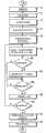
图6示出根据本发明的实施例用于校准机器人单元的方法的流程图。Fig. 6 shows a flowchart of a method for calibrating a robotic cell according to an embodiment of the invention.
具体实施方式Detailed ways
图1示出位于例如工厂的现场(site)的机器人单元(robot cell)。机器人单元包括机械手1、用于控制机械手1的移动的机器人控制单元2、和包括显示屏4的手持示教器单元3。示教器单元与控制单元2通信并且用于对机器人进行示教和编程。示教器单元3还设置有用于手动移动(也表示成轻推)机械手1的装置,如操纵杆或轻推按钮。机器人单元还包括目标物8,在这个例子中是桌子。机械手1被编程为执行与目标物8有关的工作。参考图3更详细地描述控制单元2。Figure 1 shows a robot cell located at a site such as a factory. The robot unit includes a
图1还示出了位于离线编程现场的计算机单元10,例如个人计算机(PC)。在离线现场依靠计算机单元10对机器人单元进行编程。计算机单元10设置有用于对机械手的移动进行模拟和编程的离线编程工具。从编程工具输出的是包括多个目标点的机器人程序。编程工具包括用于基于多个不同类型的目标物的模型生成三维图形的图形部件。计算机单元10包括图形显示屏12和用于将数据输入到计算机单元10的用户输入装置(未示出)。图形显示屏12是例如触摸屏,使得用户可以经由屏幕与计算机单元交互。然而,在另一实施例中,输入装置可以是键盘和定点设备。计算机单元10包括多个软件模块和用于执行软件模块的硬件。将参考图2更详细地描述计算机单元10。Figure 1 also shows a
计算机单元10和机器人控制单元2经由通信链路14彼此通信。当生成机器人程序时,机器人程序例如经由通信链路14转移到控制单元2。然而,在执行机器人程序之前,必须校准真实的机器人单元并且基于校准来校正机器人程序的目标点。计算机单元10和控制单元2设置有配置成有助于工作单元(work cell)的校准的软件模块,如图2和3所示。The
程序员用目标物的三维模型对期望的路径和机器人移动进行编程。许多路径和目标点与三维世界中的目标物相关联。过程应用移动目标(process application movement target)总是与三维目标物相关联。通常,编程的路径中的实际位置与关于目标物定义的参考系有关。参考系是相对于目标物固定的坐标系。参考系的位置和方向由目标物的位置和方向来确定。如果坐标系中有多于一个目标物,参考系针对每个目标物来定义。参考系是在公共世界坐标系中定义的。因此,程序员可以移动三维目标物并且目标点被相关地移动。当用户完成三维模拟、布局、并生成机器人程序时,是时候将这些放到真实机器人上了。A programmer uses a 3D model of the object to program the desired path and robot movement. Many paths and goal points are associated with objects in the three-dimensional world. A process application movement target is always associated with a 3D object. Usually, the actual position in the programmed path is related to a frame of reference defined with respect to the object. A reference frame is a coordinate system that is fixed relative to an object. The position and orientation of the frame of reference is determined by the position and orientation of the target. If there is more than one object in the coordinate system, a reference frame is defined for each object. A frame of reference is defined in a common world coordinate system. Thus, the programmer can move the three-dimensional object and the object point is moved in relation. When the user finishes the 3D simulation, layout, and generates the robot program, it's time to put these on the real robot.
图2示出了表示设置有用于有助于校准的软件模块的计算机单元10的例子的方框图。计算机单元10包括用于存储目标物的图形模型和预先确定的校准点的存储位置20。存储位置20可以包括具有一组预先确定的目标物类型的库。例如,预先确定的目标物类型可以是用于支持目标物、工件或工具的机器、设备的不同类型。每个工作站类型还包括工作站类型的三维几何模型、或关于如何生成工作站的几何模型的信息。在本发明的这个实施例中,每个工作站类型还包括在工作站的校准期间要使用的校准点的序列。每个目标物的校准点数目必须是至少三个。然而,校准点数目可以多于三个,例如,典型地在3-10个的范围里。优选地,校准点被选择成对应于目标物的明确定义的结构,如角、末端、或突出部分,由此有助于机器人操作员找到校准点的位置。Figure 2 shows a block diagram representing an example of a
计算机单元还包括用于基于目标物的图形模型生成三维图形的图形部件22。在编程期间,程序员从工作站的库中选择一个或多个工作站并且机器人单元的图形表示被建立。图4示出在离线编程工具中建立的视图的例子。视图包括机器人50的图形表示和被选择的目标物52的图形表示。这个机器人单元的图形视图用于对机器人进行编程。例如,程序员可以在期望的机器人路径上输入目标点。机器人程序是基于程序员的输入和机器人单元中的目标物的几何模型自动生成的。The computer unit also includes a
计算机单元还包括机器人程序生成器24,用于基于目标物的模型和在目标点上的用户输入而针对机器人生成机器人程序。计算机单元包括校准程序生成器26,校准程序生成器26被配置成基于存储在存储位置20中的校准点的序列和程序员已经选择了哪些目标物来生成一个或多个校准程序,校准程序包括用于将机器人移动到校准点处的位置或接近校准点位置的指令。由于碰撞的风险,优选地将机器人移动到离校准点有一定距离的位置并由机器人操作员手动轻推机器人到校准点的正确位置。The computer unit also includes a
计算机单元还包括图像生成器28和用户界面生成器30。图像生成器28被配置成生成图像的序列,图像的序列包括由程序员选择要被包括在工作单元中并且因而将要被校准的目标物以及与目标物有关的校准点的位置的图形表示。图像的序列代表在校准期间机器人将要仿问的校准点的序列。为了降低机器人操作员以错误的顺序访问校准点的风险,对于每个校准点生成一个图像是优选的。因此,产生了与校准点的数目相同数目的图像。基于包括存储在存储位置20的校准点的序列的目标物的图形模型,依靠图形部件22生成图像。实际上,图像是来自于图形部件22的快照。用户界面生成器30被配置成生成步进式用户界面,步进式用户界面在校准过程中示出图像并引导用户。The computer unit also includes an
用户界面生成器30通过在向导类型(wizard type)的用户界面模板中结合由图像生成器28生成的图像的序列来产生用户界面。在可替换的实施例中,用户界面生成器30也在用户界面以及图像中结合来自校准程序生成器26生成的校准程序的程序代码,并且为机器人操作员提供从用户界面启动和停止校准程序的执行的可能性,也针对被操作的机器人提供修改校准程序的可能性。The
计算机单元10还设置有通信单元32,通信单元32用于经由通信链路14与控制单元2通信。通信单元32被配置成将机器人程序、校准程序、和包括用于校准的图像的用户界面转移到控制单元2。The
图3示出了表示控制单元2中对本发明重要的部分的方框图。控制单元2包括通信单元40以能够经由通信链路14与计算机单元10通信。控制单元2设置有用于执行机器人程序和校准程序的程序执行器42、和用于存储校准程序和机器人程序的存储单元44。因此,校准程序运行于控制单元2。用于校准的用户界面从控制单元2转移到示教器单元3,并且在显示屏4上显示。在这个例子中,控制单元2设置有校准模块46,校准模块46被配置成当机器人被定位在校准点时记录机器人的位置,以及基于对于校准点记录的机器人位置,为机器人单元中的每个目标物确定目标物的模型和真实目标物之间的位置关系。此外,校准模块被配置成基于确定的机器人单元中的目标物的模型和真实目标物之间的关系来调整机器人程序的目标点。FIG. 3 shows a block diagram representing the parts of the
图1示出在对机器人进行编程期间,显示在离线计算机单元10上的机器人单元的例子。在校准期间,示教器单元3示出目标物的三维图像和在校准期间要被访问的校准点的序列。图1中示出了这样的显示在示教器单元3上的图像的例子。对于目标物8定义了三个校准点。在这个例子中,显示在示教器单元3上的图像同时示出所有的三个校准点,且每个校准点设置有限定机器人将要访问校准点的顺序的标号1-3。Figure 1 shows an example of a robot cell displayed on an
图4示出在对机器人进行编程期间,显示在离线计算机单元10上的机器人单元的另一个例子。该图示出了机器人的图形表示50、目标物的图形表示52。在图4示出的例子中,只有一个目标物将要被校准。然而,其他的机器人单元可以包括将要被校准的多个目标物。在该图中,三个校准点示为54、56和58。为了有助于操作员移动到校准点的准确位置,校准点已经选择为目标物52的角。图5a-c示出在目标物52的校准期间显示在示教器单元3上的图像的序列。Fig. 4 shows another example of a robot cell displayed on the off-
图5a示出在机器人单元的校准期间在示教器单元3显示的第一视图。显示在示教器单元上的视图包括校准程序的可编辑的程序代码,程序代码包括用于将机器人移动到接近校准点的位置的指令。这样,对机器人操作员来说,可以从示教器单元3编辑程序代码。视图还包括图像60,图像60示出目标物52的图形表示、校准点的序列中的第一校准点54的图形表示、以及机器人指向该校准点的图形表示。视图还包括停止按钮61和启动按钮62,停止按钮61用于在机器人操作员激活时停止校准程序的执行,启动按钮62用于在机器人操作员激活时启动校准程序的执行。此外,该视图设置有记录点按钮63,记录点按钮63在被激活时存储机器人的当前位置。当机器人处在正确的校准位置时,这个记录点按钮将由机器人操作员激活。Figure 5a shows a first view displayed on the teach pendant unit 3 during calibration of the robot unit. The view displayed on the teach pendant unit includes editable program code of the calibration procedure including instructions for moving the robot to a position close to the calibration point. In this way, it is possible for the robot operator to edit the program code from the teach pendant unit 3 . The view also includes an image 60 showing a graphical representation of the
图5b示出在机器人单元的校准期间显示的视图序列中的第二视图。第二视图包括用于将机器人移动到接近校准点序列中的第二校准点的位置的校准程序的程序代码,以及示出关于目标物52的第二校准点56的位置的图像65。Figure 5b shows a second view in the sequence of views displayed during calibration of the robotic cell. The second view includes program code for a calibration procedure for moving the robot to a position close to a second calibration point in the sequence of calibration points, and an image 65 showing the position of the
图5c示出在机器人单元的校准期间显示的视图序列中的第三视图。这是序列中最后的视图。该视图包括用于将机器人移动到接近第三校准点的位置的程序代码,以及示出关于目标物52的第三校准点58的位置的图66。Figure 5c shows a third view in the sequence of views displayed during calibration of the robotic cell. This is the last view in the sequence. This view includes program code for moving the robot to a position proximate to the third calibration point, and a
根据本发明的校准系统,至少产生以下的输出:校准程序、目标物和校准点。校准程序包含将机器人移动到必要的校准位置所必需的机器人运动指令,必要的校准位置是对单元中的不同目标物进行校准所需要的。将要呈现在示教器单元的图像是通过三维模拟拍摄的图片,这些图片是自动生成的并且缩放成适合示教器单元的屏幕。这些图片示出要被校准的目标物,以及轻推机器人和进行校准时将要使用哪些点。根据本发明的优选的实施例,生成了用户界面应用程序。用户界面应用程序是基于三维模拟中的数据生成的且包含在校准过程中示出三维图像并引导用户的步进式用户界面的.NET汇编。用户界面应用程序在示教器单元上运行。界面应用程序基本上是“向导”,因为它使校准过程变得简单和直接。According to the calibration system of the present invention, at least the following outputs are generated: calibration procedure, target object and calibration points. The calibration program contains the robot movement instructions necessary to move the robot to the necessary calibration positions required to calibrate the different objects in the cell. The images to be presented on the teach pendant unit are pictures taken through 3D simulation, which are automatically generated and scaled to fit the screen of the teach pendant unit. These pictures show the objects to be calibrated and which points will be used when jogging the robot and doing the calibration. According to a preferred embodiment of the present invention, a user interface application is generated. The user interface application is a .NET assembly that is generated based on data from the 3D simulation and contains a step-by-step user interface that shows the 3D image and guides the user through the calibration process. The user interface application runs on the teach pendant unit. The interface application is basically a "wizard" in that it makes the calibration process easy and straightforward.
在可替代的实施例中,离线编程工具产生三维图像和校准程序,但是校准程序包含用于运行校准过程的更多代码。因此,引导的校准的执行是通过机器人语言指令来运行而不是通过示教器应用汇编来运行的。In an alternative embodiment, an offline programming tool generates the 3D image and calibration program, but the calibration program contains more code for running the calibration process. Thus, the guided calibration is performed through robot language instructions rather than through the teach pendant application assembly.
在另外的替代实施例中,三维离线编程工具仍然生成校准程序和三维图像,但是机器人的控制单元已经包含接收图像和校准程序的校准引擎,然后操作员启动校准引擎。In yet another alternative embodiment, the 3D off-line programming tool still generates the calibration program and 3D images, but the robot's control unit already contains a calibration engine that receives the images and calibration programs, and the operator then activates the calibration engine.
图6示出了表示根据本发明的实施例的方法的流程图。将会理解到流程图的每块可以由计算机程序指令来实现。然而,一些步骤在离线的计算机单元10上执行,并且一些步骤在机器人控制单元2上执行,而一些步骤可以在示教器单元3上执行。在这个实施例中,步骤70-78在计算机单元10上执行,步骤80在示教器单元上执行,步骤82-94在机器人控制单元上执行。Fig. 6 shows a flowchart representing a method according to an embodiment of the invention. It will be understood that each block of the flowchart can be implemented by computer program instructions. However, some steps are performed on the off-
首先,获取与所选择的机器人单元的目标物相对应的校准点的序列(块70)。校准点从存储位置20获取。此后,基于获取的校准点的序列生成一个或多个校准程序(块72)。依靠离线编程工具的图形部件自动生成包括目标物和校准点的图形视图的图像的序列(块74)。例如,对于每个校准点生成一个图像。基于生成的图像和校准程序自动生成用于校准的用户界面程序(块76)。在这个实施例中,用户界面程序被配置成在示教器单元上执行,并且被配置成在校准过程中生成用于与用户交互的图形用户界面。将校准程序和包括图像的用户界面程序转移到机器人控制单元(块78)。在校准期间校准程序在机器人控制单元上执行,并且在校准期间用户界面程序在示教器单元上执行。机器人控制单元将用户界面程序转移到示教器单元。First, a sequence of calibration points corresponding to the object of the selected robotic cell is acquired (block 70). Calibration points are retrieved from
当机器人操作员命令启动校准时,示教器单元上的用户界面显示序列的第一视图,例如图5a示出的视图,视图包括关于目标物的第一校准点的图像(块80)。机器人操作员通过激活视图中的启动按钮通过显示的用户界面来启动校准程序(块82)。启动命令从示教器单元发送到机器人控制单元,机器人控制单元在接收到启动命令时启动校准程序的执行,并且机器人被自动移动到接近校准点的位置(块84)。当机器人已经被移动到接近校准点的位置时,校准程序自动停止。现在轮到机器人操作员将机器人手动轻推到校准点。当前校准点和目标物的显示的图像给操作员提供了关于校准点的位置的信息。当操作员已经将机器人轻推到校准点的准确位置时,操作员激活用户界面上的记录按钮并且记录命令被发送到机器人控制单元。当机器人接收了记录指令(块86),机器人的当前位置被存储(块88)。例如,机器人位置包括关于机器人的轴的连接角的信息。When the robot operator commands initiation of calibration, the user interface on the teach pendant unit displays a first view of the sequence, such as that shown in Figure 5a, comprising an image of the first calibration point on the target (block 80). The robot operator initiates the calibration procedure through the displayed user interface by activating the start button in the view (block 82). A start command is sent from the teach pendant unit to the robot control unit which, upon receipt of the start command, initiates execution of the calibration procedure and the robot is automatically moved to a position close to the calibration point (block 84). The calibration procedure stops automatically when the robot has been moved close to the calibration point. Now it is the robot operator's turn to manually jog the robot to the calibration point. The displayed image of the current calibration point and the target object provides the operator with information about the location of the calibration point. When the operator has jogged the robot to the exact position of the calibration point, the operator activates the record button on the user interface and a record command is sent to the robot control unit. When the robot receives the log command (block 86), the robot's current position is stored (block 88). For example, the robot position includes information about the connection angles of the axes of the robot.
对于序列中的每个校准点重复步骤82-88。当机器人已经访问了所有的校准点并且对于每个校准点记录了机器人的位置时(块90),可以计算目标物模型的位置与真实目标物的位置之间的关系(块92)。这个例子中,在机器人控制单元中进行计算。然而,在可替代的实施例中,可以在远程计算机上进行这种计算。记录的机器人位置被用来计算真实目标物的实际位置。例如,通过在模型上的校准点的位置和真实目标物的位置之间进行最佳拟合,来计算目标物的模型和真实目标物之间的关系。然后更新工作目标物的真实位置,并且由于保持了编程的路径上的位置和工作目标物之间的关系,因此将更新编程的路径上的所有位置(块94)。当工作目标物的真实位置被更新时,参考系也被更新。因此,没有必要计算路径的新位置。Repeat steps 82-88 for each calibration point in the sequence. When the robot has visited all calibration points and recorded the robot's position for each calibration point (block 90), the relationship between the position of the target model and the position of the real target can be calculated (block 92). In this example, calculations are performed in the robot control unit. However, in alternative embodiments, such calculations may be performed on a remote computer. The recorded robot position is used to calculate the actual position of the real object. For example, the relationship between the model of the target and the real target is calculated by performing a best fit between the positions of the calibration points on the model and the positions of the real target. The real position of the work object is then updated, and since the relationship between the position on the programmed path and the work object is maintained, all positions on the programmed path will be updated (block 94). When the true position of the work object is updated, the frame of reference is also updated. Therefore, there is no need to calculate a new location for the path.
本发明不限于公开的实施例,而是可以在所附权利要求的范围内进行变化和修改。例如,机器人单元可以包括多个目标物。然后,校准点的序列取决于目标物要被校准的限定的顺序。在这种情况下,基于限定的目标物要被校准的顺序生成用户界面。此外,机器人单元也可以包含多个机器人。The invention is not limited to the disclosed embodiments but may be varied and modified within the scope of the appended claims. For example, a robotic cell may include multiple objects. The sequence of calibration points then depends on the defined order in which the objects are to be calibrated. In this case, the user interface is generated based on the order in which the defined objects are to be calibrated. Furthermore, a robot cell can also contain multiple robots.
Claims (16)
Applications Claiming Priority (1)
| Application Number | Priority Date | Filing Date | Title |
|---|---|---|---|
| PCT/EP2008/057139WO2009149740A1 (en) | 2008-06-09 | 2008-06-09 | A method and a system for facilitating calibration of an off-line programmed robot cell |
Publications (2)
| Publication Number | Publication Date |
|---|---|
| CN102119072A CN102119072A (en) | 2011-07-06 |
| CN102119072Btrue CN102119072B (en) | 2013-09-11 |
Family
ID=40344847
Family Applications (1)
| Application Number | Title | Priority Date | Filing Date |
|---|---|---|---|
| CN200880129169.XAActiveCN102119072B (en) | 2008-06-09 | 2008-06-09 | A method and a system for facilitating calibration of an off-line programmed robot cell |
Country Status (5)
| Country | Link |
|---|---|
| US (1) | US7945349B2 (en) |
| EP (1) | EP2282873B1 (en) |
| CN (1) | CN102119072B (en) |
| ES (1) | ES2412393T3 (en) |
| WO (1) | WO2009149740A1 (en) |
Cited By (1)
| Publication number | Priority date | Publication date | Assignee | Title |
|---|---|---|---|---|
| US11433541B2 (en) | 2019-12-18 | 2022-09-06 | Industrial Technology Research Institute | Automated calibration system and method for a workpiece coordinate frame of a robot |
Families Citing this family (124)
| Publication number | Priority date | Publication date | Assignee | Title |
|---|---|---|---|---|
| DE10361018C9 (en)* | 2003-12-23 | 2021-03-04 | QUISS Qualitäts-Inspektionssysteme und Service GmbH | Method for recognizing a structure to be applied to a substrate with a plurality of cameras and a device therefor |
| DE102006031580A1 (en) | 2006-07-03 | 2008-01-17 | Faro Technologies, Inc., Lake Mary | Method and device for the three-dimensional detection of a spatial area |
| US9104195B2 (en) | 2006-12-20 | 2015-08-11 | Lincoln Global, Inc. | Welding job sequencer |
| US10994358B2 (en) | 2006-12-20 | 2021-05-04 | Lincoln Global, Inc. | System and method for creating or modifying a welding sequence based on non-real world weld data |
| US9937577B2 (en) | 2006-12-20 | 2018-04-10 | Lincoln Global, Inc. | System for a welding sequencer |
| US9330575B2 (en) | 2008-08-21 | 2016-05-03 | Lincoln Global, Inc. | Tablet-based welding simulator |
| US9280913B2 (en) | 2009-07-10 | 2016-03-08 | Lincoln Global, Inc. | Systems and methods providing enhanced education and training in a virtual reality environment |
| US8915740B2 (en) | 2008-08-21 | 2014-12-23 | Lincoln Global, Inc. | Virtual reality pipe welding simulator |
| US9483959B2 (en) | 2008-08-21 | 2016-11-01 | Lincoln Global, Inc. | Welding simulator |
| US9196169B2 (en) | 2008-08-21 | 2015-11-24 | Lincoln Global, Inc. | Importing and analyzing external data using a virtual reality welding system |
| US8834168B2 (en) | 2008-08-21 | 2014-09-16 | Lincoln Global, Inc. | System and method providing combined virtual reality arc welding and three-dimensional (3D) viewing |
| US8884177B2 (en) | 2009-11-13 | 2014-11-11 | Lincoln Global, Inc. | Systems, methods, and apparatuses for monitoring weld quality |
| US8747116B2 (en) | 2008-08-21 | 2014-06-10 | Lincoln Global, Inc. | System and method providing arc welding training in a real-time simulated virtual reality environment using real-time weld puddle feedback |
| US8851896B2 (en) | 2008-08-21 | 2014-10-07 | Lincoln Global, Inc. | Virtual reality GTAW and pipe welding simulator and setup |
| US9318026B2 (en) | 2008-08-21 | 2016-04-19 | Lincoln Global, Inc. | Systems and methods providing an enhanced user experience in a real-time simulated virtual reality welding environment |
| US8911237B2 (en) | 2008-08-21 | 2014-12-16 | Lincoln Global, Inc. | Virtual reality pipe welding simulator and setup |
| US8274013B2 (en) | 2009-03-09 | 2012-09-25 | Lincoln Global, Inc. | System for tracking and analyzing welding activity |
| US9551575B2 (en) | 2009-03-25 | 2017-01-24 | Faro Technologies, Inc. | Laser scanner having a multi-color light source and real-time color receiver |
| DE102009015920B4 (en) | 2009-03-25 | 2014-11-20 | Faro Technologies, Inc. | Device for optically scanning and measuring an environment |
| US9221117B2 (en) | 2009-07-08 | 2015-12-29 | Lincoln Global, Inc. | System for characterizing manual welding operations |
| US9230449B2 (en) | 2009-07-08 | 2016-01-05 | Lincoln Global, Inc. | Welding training system |
| US9773429B2 (en) | 2009-07-08 | 2017-09-26 | Lincoln Global, Inc. | System and method for manual welder training |
| US10748447B2 (en) | 2013-05-24 | 2020-08-18 | Lincoln Global, Inc. | Systems and methods providing a computerized eyewear device to aid in welding |
| US9011154B2 (en) | 2009-07-10 | 2015-04-21 | Lincoln Global, Inc. | Virtual welding system |
| US8569655B2 (en) | 2009-10-13 | 2013-10-29 | Lincoln Global, Inc. | Welding helmet with integral user interface |
| US9468988B2 (en) | 2009-11-13 | 2016-10-18 | Lincoln Global, Inc. | Systems, methods, and apparatuses for monitoring weld quality |
| US8569646B2 (en) | 2009-11-13 | 2013-10-29 | Lincoln Global, Inc. | Systems, methods, and apparatuses for monitoring weld quality |
| DE102009057101A1 (en) | 2009-11-20 | 2011-05-26 | Faro Technologies, Inc., Lake Mary | Device for optically scanning and measuring an environment |
| US9113023B2 (en) | 2009-11-20 | 2015-08-18 | Faro Technologies, Inc. | Three-dimensional scanner with spectroscopic energy detector |
| US9529083B2 (en) | 2009-11-20 | 2016-12-27 | Faro Technologies, Inc. | Three-dimensional scanner with enhanced spectroscopic energy detector |
| US8630314B2 (en) | 2010-01-11 | 2014-01-14 | Faro Technologies, Inc. | Method and apparatus for synchronizing measurements taken by multiple metrology devices |
| US8615893B2 (en) | 2010-01-20 | 2013-12-31 | Faro Technologies, Inc. | Portable articulated arm coordinate measuring machine having integrated software controls |
| US8677643B2 (en) | 2010-01-20 | 2014-03-25 | Faro Technologies, Inc. | Coordinate measurement machines with removable accessories |
| US9163922B2 (en) | 2010-01-20 | 2015-10-20 | Faro Technologies, Inc. | Coordinate measurement machine with distance meter and camera to determine dimensions within camera images |
| US8875409B2 (en) | 2010-01-20 | 2014-11-04 | Faro Technologies, Inc. | Coordinate measurement machines with removable accessories |
| US8898919B2 (en) | 2010-01-20 | 2014-12-02 | Faro Technologies, Inc. | Coordinate measurement machine with distance meter used to establish frame of reference |
| US8284407B2 (en) | 2010-01-20 | 2012-10-09 | Faro Technologies, Inc. | Coordinate measuring machine having an illuminated probe end and method of operation |
| US9628775B2 (en) | 2010-01-20 | 2017-04-18 | Faro Technologies, Inc. | Articulated arm coordinate measurement machine having a 2D camera and method of obtaining 3D representations |
| US9607239B2 (en) | 2010-01-20 | 2017-03-28 | Faro Technologies, Inc. | Articulated arm coordinate measurement machine having a 2D camera and method of obtaining 3D representations |
| US8832954B2 (en) | 2010-01-20 | 2014-09-16 | Faro Technologies, Inc. | Coordinate measurement machines with removable accessories |
| US8942940B2 (en) | 2010-01-20 | 2015-01-27 | Faro Technologies, Inc. | Portable articulated arm coordinate measuring machine and integrated electronic data processing system |
| US9879976B2 (en) | 2010-01-20 | 2018-01-30 | Faro Technologies, Inc. | Articulated arm coordinate measurement machine that uses a 2D camera to determine 3D coordinates of smoothly continuous edge features |
| WO2011090895A1 (en) | 2010-01-20 | 2011-07-28 | Faro Technologies, Inc. | Portable articulated arm coordinate measuring machine with multi-bus arm technology |
| DE102010020925B4 (en) | 2010-05-10 | 2014-02-27 | Faro Technologies, Inc. | Method for optically scanning and measuring an environment |
| SE1050763A1 (en)* | 2010-07-08 | 2010-07-12 | Abb Research Ltd | A method for calibration of a mobile robot |
| US9906838B2 (en) | 2010-07-12 | 2018-02-27 | Time Warner Cable Enterprises Llc | Apparatus and methods for content delivery and message exchange across multiple content delivery networks |
| GB2501390B (en) | 2010-09-08 | 2014-08-06 | Faro Tech Inc | A laser scanner or laser tracker having a projector |
| US9168654B2 (en) | 2010-11-16 | 2015-10-27 | Faro Technologies, Inc. | Coordinate measuring machines with dual layer arm |
| US8607536B2 (en) | 2011-01-14 | 2013-12-17 | Faro Technologies, Inc. | Case for a device |
| US9266241B2 (en) | 2011-03-14 | 2016-02-23 | Matthew E. Trompeter | Robotic work object cell calibration system |
| US20120290130A1 (en)* | 2011-05-10 | 2012-11-15 | Agile Planet, Inc. | Method to Model and Program a Robotic Workcell |
| JP6193554B2 (en)* | 2011-11-04 | 2017-09-06 | ファナック アメリカ コーポレイション | Robot teaching apparatus having a three-dimensional display unit |
| DE102012100609A1 (en) | 2012-01-25 | 2013-07-25 | Faro Technologies, Inc. | Device for optically scanning and measuring an environment |
| JP2015513669A (en)* | 2012-02-21 | 2015-05-14 | ファロ テクノロジーズ インコーポレーテッド | Portable articulated arm coordinate measuring machine with integrated software control |
| DE102012103030B3 (en)* | 2012-04-05 | 2013-05-23 | Reis Group Holding Gmbh & Co. Kg | Method for operating an industrial robot |
| US20160093233A1 (en) | 2012-07-06 | 2016-03-31 | Lincoln Global, Inc. | System for characterizing manual welding operations on pipe and other curved structures |
| US9767712B2 (en) | 2012-07-10 | 2017-09-19 | Lincoln Global, Inc. | Virtual reality pipe welding simulator and setup |
| US8997362B2 (en) | 2012-07-17 | 2015-04-07 | Faro Technologies, Inc. | Portable articulated arm coordinate measuring machine with optical communications bus |
| JPWO2014013605A1 (en)* | 2012-07-20 | 2016-06-30 | 株式会社安川電機 | Robot simulator, robot teaching apparatus, and robot teaching method |
| US10067231B2 (en) | 2012-10-05 | 2018-09-04 | Faro Technologies, Inc. | Registration calculation of three-dimensional scanner data performed between scans based on measurements by two-dimensional scanner |
| DE102012109481A1 (en) | 2012-10-05 | 2014-04-10 | Faro Technologies, Inc. | Device for optically scanning and measuring an environment |
| US9513107B2 (en) | 2012-10-05 | 2016-12-06 | Faro Technologies, Inc. | Registration calculation between three-dimensional (3D) scans based on two-dimensional (2D) scan data from a 3D scanner |
| US9724584B1 (en) | 2012-11-15 | 2017-08-08 | Airborne Athletics, Inc. | Sports training machine |
| US9417625B2 (en)* | 2012-11-29 | 2016-08-16 | Fanuc America Corporation | Robot system calibration method |
| US10664994B2 (en) | 2013-02-25 | 2020-05-26 | Cognex Corporation | System and method for calibration of machine vision cameras along at least three discrete planes |
| US9452533B2 (en)* | 2013-05-15 | 2016-09-27 | Hexagon Technology Center Gmbh | Robot modeling and positioning |
| US10930174B2 (en) | 2013-05-24 | 2021-02-23 | Lincoln Global, Inc. | Systems and methods providing a computerized eyewear device to aid in welding |
| SE537534C2 (en)* | 2013-08-27 | 2015-06-02 | Cognibotics Ab | Method and system for determining at least one property of a manipulator |
| DE102013014467A1 (en)* | 2013-08-30 | 2015-03-05 | Dürr Ecoclean GmbH | "Method for measuring and / or calibrating a robot" |
| US20150072323A1 (en) | 2013-09-11 | 2015-03-12 | Lincoln Global, Inc. | Learning management system for a real-time simulated virtual reality welding training environment |
| US10083627B2 (en) | 2013-11-05 | 2018-09-25 | Lincoln Global, Inc. | Virtual reality and real welding training system and method |
| US9836987B2 (en) | 2014-02-14 | 2017-12-05 | Lincoln Global, Inc. | Virtual reality pipe welding simulator and setup |
| US9387589B2 (en)* | 2014-02-25 | 2016-07-12 | GM Global Technology Operations LLC | Visual debugging of robotic tasks |
| US9613308B2 (en) | 2014-04-03 | 2017-04-04 | Brain Corporation | Spoofing remote control apparatus and methods |
| US9630317B2 (en)* | 2014-04-03 | 2017-04-25 | Brain Corporation | Learning apparatus and methods for control of robotic devices via spoofing |
| JP6311421B2 (en)* | 2014-04-10 | 2018-04-18 | 株式会社安川電機 | Teaching system, robot system, and teaching method |
| CN106462140B (en)* | 2014-04-30 | 2019-04-26 | Abb瑞士股份有限公司 | Method for calibrating tool center point of industrial robot system |
| US20150331415A1 (en)* | 2014-05-16 | 2015-11-19 | Microsoft Corporation | Robotic task demonstration interface |
| US9555545B2 (en)* | 2014-05-21 | 2017-01-31 | Bot & Dolly, Llc | Systems and methods for time-based parallel robotic operation |
| EP3111440A1 (en) | 2014-06-02 | 2017-01-04 | Lincoln Global, Inc. | System and method for manual welder training |
| US9579790B2 (en) | 2014-09-17 | 2017-02-28 | Brain Corporation | Apparatus and methods for removal of learned behaviors in robots |
| US9860077B2 (en) | 2014-09-17 | 2018-01-02 | Brain Corporation | Home animation apparatus and methods |
| US9821470B2 (en) | 2014-09-17 | 2017-11-21 | Brain Corporation | Apparatus and methods for context determination using real time sensor data |
| US9849588B2 (en) | 2014-09-17 | 2017-12-26 | Brain Corporation | Apparatus and methods for remotely controlling robotic devices |
| JP6006277B2 (en)* | 2014-11-06 | 2016-10-12 | ファナック株式会社 | Program correcting apparatus and program correcting method for industrial robot |
| DE202015009616U1 (en) | 2015-08-14 | 2018-08-30 | Franka Emika Gmbh | Robot system and housing part for such a robot system |
| DE102015012962B4 (en)* | 2015-10-08 | 2024-08-22 | Franka Emika Gmbh | Robot system |
| US10657802B2 (en) | 2015-11-02 | 2020-05-19 | The Johns Hopkins University | Method, device, and computer-readable medium for mobile device management of collaborative industrial robot |
| DE102015122844A1 (en) | 2015-12-27 | 2017-06-29 | Faro Technologies, Inc. | 3D measuring device with battery pack |
| US10500726B2 (en)* | 2016-04-25 | 2019-12-10 | Kindred Systems Inc. | Facilitating device control |
| US10295972B2 (en) | 2016-04-29 | 2019-05-21 | Brain Corporation | Systems and methods to operate controllable devices with gestures and/or noises |
| EP3243607B1 (en)* | 2016-05-09 | 2021-01-27 | OpiFlex Automation AB | A system and a method for programming an industrial robot |
| US11577139B1 (en) | 2016-09-30 | 2023-02-14 | Airborne Athletics, Inc. | Basketball training system |
| US10571902B2 (en)* | 2016-10-12 | 2020-02-25 | Sisu Devices Llc | Robotic programming and motion control |
| EP3319066A1 (en) | 2016-11-04 | 2018-05-09 | Lincoln Global, Inc. | Magnetic frequency selection for electromagnetic position tracking |
| US10878591B2 (en) | 2016-11-07 | 2020-12-29 | Lincoln Global, Inc. | Welding trainer utilizing a head up display to display simulated and real-world objects |
| US10913125B2 (en) | 2016-11-07 | 2021-02-09 | Lincoln Global, Inc. | Welding system providing visual and audio cues to a welding helmet with a display |
| US10596436B1 (en) | 2016-11-08 | 2020-03-24 | Airborne Athletics, Inc. | Basketball training system |
| US10642244B2 (en)* | 2016-12-19 | 2020-05-05 | Autodesk, Inc. | Robotic augmentation of creative tasks |
| EP3338969A3 (en)* | 2016-12-22 | 2018-07-25 | Seiko Epson Corporation | Control apparatus, robot and robot system |
| JP6469159B2 (en)* | 2017-04-10 | 2019-02-13 | ファナック株式会社 | Offline programming apparatus and method with work position detection program generation function by contact sensor |
| US10331728B2 (en) | 2017-05-30 | 2019-06-25 | General Electric Company | System and method of robot calibration using image data |
| US10997872B2 (en) | 2017-06-01 | 2021-05-04 | Lincoln Global, Inc. | Spring-loaded tip assembly to support simulated shielded metal arc welding |
| JP6626065B2 (en)* | 2017-10-31 | 2019-12-25 | ファナック株式会社 | Robot teaching device that warns or corrects the displacement of the teaching point or teaching line |
| AT520775B1 (en)* | 2017-12-14 | 2020-04-15 | Wittmann Kunststoffgeraete | Procedure for validation of programmed sequences or |
| US11475792B2 (en) | 2018-04-19 | 2022-10-18 | Lincoln Global, Inc. | Welding simulator with dual-user configuration |
| US11557223B2 (en) | 2018-04-19 | 2023-01-17 | Lincoln Global, Inc. | Modular and reconfigurable chassis for simulated welding training |
| PL3557351T3 (en)* | 2018-04-20 | 2021-06-14 | Rittal Gmbh & Co. Kg | System and method for assembling a modular control cabinet feature |
| WO2020037496A1 (en)* | 2018-08-21 | 2020-02-27 | 西门子股份公司 | Method, device and system for correcting offline programming program, medium, and terminal |
| DE102018214417B3 (en)* | 2018-08-27 | 2019-07-25 | Volkswagen Aktiengesellschaft | Method for programming a robot as well as computing device and computer program |
| CN109544796A (en)* | 2018-11-30 | 2019-03-29 | 湖南金码智能设备制造有限公司 | A kind of XY type is without screen automatic selling terminal and its cargo path position calibration method |
| CN109623206B (en)* | 2018-12-19 | 2020-05-19 | 清华大学 | A method for optimizing the welding torch pose for offline planning in robotic pipe welding |
| EP3921121A1 (en)* | 2019-02-07 | 2021-12-15 | ABB Schweiz AG | Method of calibrating a tool of an industrial robot, control system and industrial robot |
| JP7436796B2 (en)* | 2019-12-16 | 2024-02-22 | 株式会社デンソーウェーブ | Robot program creation support device |
| CN115397629A (en)* | 2020-03-30 | 2022-11-25 | 发那科株式会社 | Off-line simulation system |
| IL274911B2 (en)* | 2020-05-25 | 2023-10-01 | Metalix Cad/Cam Ltd | Device and method for calibrating a robotic cell |
| JP7512743B2 (en)* | 2020-07-30 | 2024-07-09 | セイコーエプソン株式会社 | Teaching method and robot system |
| CN114074333A (en)* | 2020-08-19 | 2022-02-22 | 常州星宇车灯股份有限公司 | Calibration method for off-line program of car lamp shell gluing robot |
| TW202234184A (en)* | 2021-02-25 | 2022-09-01 | 日商發那科股份有限公司 | A simulation device using 3D position information obtained from the output of a vision sensor |
| US11931908B2 (en)* | 2021-03-16 | 2024-03-19 | Intrinsic Innovation Llc | Detecting robotic calibration accuracy discrepancies |
| US20240139959A1 (en)* | 2021-04-19 | 2024-05-02 | Fanuc Corporation | Program generation device and robot control device |
| US11911915B2 (en)* | 2021-06-09 | 2024-02-27 | Intrinsic Innovation Llc | Determining robotic calibration processes |
| IT202100027485A1 (en) | 2021-10-26 | 2023-04-26 | Glance Vision Tech S R L | APPARATUS AND PROCEDURE FOR PROGRAMMING ROBOTS BY MEANS OF DEMONSTRATION |
| US12194357B1 (en) | 2022-01-24 | 2025-01-14 | Airborne Athletics, Inc. | Basketball training system with computer vision functionality |
Citations (8)
| Publication number | Priority date | Publication date | Assignee | Title |
|---|---|---|---|---|
| EP0792726A4 (en)* | 1995-09-18 | 1997-10-15 | ||
| EP0997236A1 (en)* | 1998-10-30 | 2000-05-03 | Fanuc Ltd | Image processing apparatus for a robot |
| CA2246076C (en)* | 1997-09-10 | 2001-04-10 | Honda Giken Kogyo Kabushiki Kaisha .) | Off-line teaching apparatus |
| EP1462224A2 (en)* | 2003-02-27 | 2004-09-29 | Fanuc Ltd | Taught position modification device |
| CN1680079A (en)* | 2004-04-07 | 2005-10-12 | 发那科株式会社 | Offline programming device |
| CN1983091A (en)* | 2005-12-16 | 2007-06-20 | 发那科株式会社 | Offline programming device |
| CN101092031A (en)* | 2007-07-12 | 2007-12-26 | 上海交通大学 | Off line programming tool for industrial robot |
| EP1510894B1 (en)* | 2003-08-27 | 2008-06-04 | Fanuc Ltd | Robot program position correcting apparatus |
Family Cites Families (1)
| Publication number | Priority date | Publication date | Assignee | Title |
|---|---|---|---|---|
| EP1842631B1 (en) | 2006-04-03 | 2008-11-19 | ABB Research Ltd | Apparatus and method for automatic path generation for an industrial robot |
- 2008
- 2008-06-09CNCN200880129169.XApatent/CN102119072B/enactiveActive
- 2008-06-09WOPCT/EP2008/057139patent/WO2009149740A1/enactiveApplication Filing
- 2008-06-09EPEP08760708.1Apatent/EP2282873B1/enactiveActive
- 2008-06-09USUS12/311,039patent/US7945349B2/enactiveActive
- 2008-06-09ESES08760708Tpatent/ES2412393T3/enactiveActive
Patent Citations (9)
| Publication number | Priority date | Publication date | Assignee | Title |
|---|---|---|---|---|
| EP0792726A4 (en)* | 1995-09-18 | 1997-10-15 | ||
| CA2246076C (en)* | 1997-09-10 | 2001-04-10 | Honda Giken Kogyo Kabushiki Kaisha .) | Off-line teaching apparatus |
| EP0997236A1 (en)* | 1998-10-30 | 2000-05-03 | Fanuc Ltd | Image processing apparatus for a robot |
| US7151848B1 (en)* | 1998-10-30 | 2006-12-19 | Fanuc Ltd | Image processing apparatus for robot |
| EP1462224A2 (en)* | 2003-02-27 | 2004-09-29 | Fanuc Ltd | Taught position modification device |
| EP1510894B1 (en)* | 2003-08-27 | 2008-06-04 | Fanuc Ltd | Robot program position correcting apparatus |
| CN1680079A (en)* | 2004-04-07 | 2005-10-12 | 发那科株式会社 | Offline programming device |
| CN1983091A (en)* | 2005-12-16 | 2007-06-20 | 发那科株式会社 | Offline programming device |
| CN101092031A (en)* | 2007-07-12 | 2007-12-26 | 上海交通大学 | Off line programming tool for industrial robot |
Non-Patent Citations (4)
| Title |
|---|
| 刘美华等.新的机器人自校正控制方案.《机器人》.1987,(第1期), |
| 单自由度遥操作系统的虚拟现实环境建模研究;李会军等;《测控技术》;20050218;第24卷(第2期);全文* |
| 新的机器人自校正控制方案;刘美华等;《机器人》;19870829(第1期);全文* |
| 李会军等.单自由度遥操作系统的虚拟现实环境建模研究.《测控技术》.2005,第24卷(第2期), |
Cited By (1)
| Publication number | Priority date | Publication date | Assignee | Title |
|---|---|---|---|---|
| US11433541B2 (en) | 2019-12-18 | 2022-09-06 | Industrial Technology Research Institute | Automated calibration system and method for a workpiece coordinate frame of a robot |
Also Published As
| Publication number | Publication date |
|---|---|
| CN102119072A (en) | 2011-07-06 |
| ES2412393T3 (en) | 2013-07-11 |
| WO2009149740A1 (en) | 2009-12-17 |
| US7945349B2 (en) | 2011-05-17 |
| US20100262288A1 (en) | 2010-10-14 |
| EP2282873A1 (en) | 2011-02-16 |
| EP2282873B1 (en) | 2013-04-10 |
Similar Documents
| Publication | Publication Date | Title |
|---|---|---|
| CN102119072B (en) | A method and a system for facilitating calibration of an off-line programmed robot cell | |
| Ong et al. | Augmented reality-assisted robot programming system for industrial applications | |
| EP1936458B1 (en) | Device, method, program and recording medium for robot offline programming | |
| Blankemeyer et al. | Intuitive robot programming using augmented reality | |
| CN108453702B (en) | Robot simulator, robot system, and simulation method | |
| US8504188B2 (en) | Device and method for the computer-assisted generation of a manipulator path | |
| JP3950805B2 (en) | Teaching position correction device | |
| EP1756684B1 (en) | Method and system for off-line programming of multiple interacting robots | |
| US20150190926A1 (en) | Method and system for off-line programming of multiple interacting robots | |
| JP2001105359A (en) | Graphic display device for robot system | |
| GB2473129A (en) | Off-line robot teaching method | |
| EP1712969A2 (en) | Robot program correcting apparatus | |
| JP2005135278A (en) | Simulation apparatus | |
| KR20150044812A (en) | Teaching system and teaching method | |
| WO2004085120A1 (en) | Robot simulation device, and robot simulation program | |
| Fang et al. | Orientation planning of robot end-effector using augmented reality | |
| TW202024824A (en) | Machine tool system | |
| JP7674464B2 (en) | Simulation device using 3D position information obtained from the output of a visual sensor | |
| Patwardhan et al. | Kinematic analysis and development of simulation software for nex dexter robotic manipulator | |
| JP2021059012A (en) | Information processing device, information processing method and robot system | |
| JP2010218036A (en) | Robot off-line programming system | |
| JP2022076814A (en) | Program generation system, robot system, program generation method, and generation program | |
| JP5272447B2 (en) | Numerical control machine operation simulator | |
| JP4829151B2 (en) | Robot program evaluation / correction method and robot program evaluation / correction device | |
| KR20200097896A (en) | Apparatus and method for generating manipulator URDF file |
Legal Events
| Date | Code | Title | Description |
|---|---|---|---|
| C06 | Publication | ||
| PB01 | Publication | ||
| C10 | Entry into substantive examination | ||
| SE01 | Entry into force of request for substantive examination | ||
| C41 | Transfer of patent application or patent right or utility model | ||
| TA01 | Transfer of patent application right | Effective date of registration:20120530 Address after:Zurich Applicant after:ABB T & D Technology Ltd. Address before:Sweden Westrm J Applicant before:ABB T & D Technology Ltd. | |
| C14 | Grant of patent or utility model | ||
| GR01 | Patent grant | ||
| TR01 | Transfer of patent right | ||
| TR01 | Transfer of patent right | Effective date of registration:20180517 Address after:Baden, Switzerland Patentee after:ABB TECHNOLOGY LTD. Address before:Zurich Patentee before:ABB T & D Technology Ltd. |