CN102119009B - Catheter and method for improved ablation - Google Patents
Catheter and method for improved ablationDownload PDFInfo
- Publication number
- CN102119009B CN102119009BCN2009801280365ACN200980128036ACN102119009BCN 102119009 BCN102119009 BCN 102119009BCN 2009801280365 ACN2009801280365 ACN 2009801280365ACN 200980128036 ACN200980128036 ACN 200980128036ACN 102119009 BCN102119009 BCN 102119009B
- Authority
- CN
- China
- Prior art keywords
- catheter
- electrode
- electrodes
- ablation
- tissue
- Prior art date
- Legal status (The legal status is an assumption and is not a legal conclusion. Google has not performed a legal analysis and makes no representation as to the accuracy of the status listed.)
- Expired - Fee Related
Links
Images


Classifications
- A—HUMAN NECESSITIES
- A61—MEDICAL OR VETERINARY SCIENCE; HYGIENE
- A61B—DIAGNOSIS; SURGERY; IDENTIFICATION
- A61B18/00—Surgical instruments, devices or methods for transferring non-mechanical forms of energy to or from the body
- A61B18/04—Surgical instruments, devices or methods for transferring non-mechanical forms of energy to or from the body by heating
- A61B18/12—Surgical instruments, devices or methods for transferring non-mechanical forms of energy to or from the body by heating by passing a current through the tissue to be heated, e.g. high-frequency current
- A61B18/14—Probes or electrodes therefor
- A61B18/1492—Probes or electrodes therefor having a flexible, catheter-like structure, e.g. for heart ablation
- A—HUMAN NECESSITIES
- A61—MEDICAL OR VETERINARY SCIENCE; HYGIENE
- A61B—DIAGNOSIS; SURGERY; IDENTIFICATION
- A61B18/00—Surgical instruments, devices or methods for transferring non-mechanical forms of energy to or from the body
- A61B2018/00005—Cooling or heating of the probe or tissue immediately surrounding the probe
- A61B2018/00011—Cooling or heating of the probe or tissue immediately surrounding the probe with fluids
- A61B2018/00029—Cooling or heating of the probe or tissue immediately surrounding the probe with fluids open
- A—HUMAN NECESSITIES
- A61—MEDICAL OR VETERINARY SCIENCE; HYGIENE
- A61B—DIAGNOSIS; SURGERY; IDENTIFICATION
- A61B18/00—Surgical instruments, devices or methods for transferring non-mechanical forms of energy to or from the body
- A61B2018/00053—Mechanical features of the instrument of device
- A61B2018/00214—Expandable means emitting energy, e.g. by elements carried thereon
- A—HUMAN NECESSITIES
- A61—MEDICAL OR VETERINARY SCIENCE; HYGIENE
- A61B—DIAGNOSIS; SURGERY; IDENTIFICATION
- A61B18/00—Surgical instruments, devices or methods for transferring non-mechanical forms of energy to or from the body
- A61B2018/00315—Surgical instruments, devices or methods for transferring non-mechanical forms of energy to or from the body for treatment of particular body parts
- A61B2018/00345—Vascular system
- A61B2018/00351—Heart
- A—HUMAN NECESSITIES
- A61—MEDICAL OR VETERINARY SCIENCE; HYGIENE
- A61B—DIAGNOSIS; SURGERY; IDENTIFICATION
- A61B18/00—Surgical instruments, devices or methods for transferring non-mechanical forms of energy to or from the body
- A61B2018/00571—Surgical instruments, devices or methods for transferring non-mechanical forms of energy to or from the body for achieving a particular surgical effect
- A61B2018/00577—Ablation
- A—HUMAN NECESSITIES
- A61—MEDICAL OR VETERINARY SCIENCE; HYGIENE
- A61B—DIAGNOSIS; SURGERY; IDENTIFICATION
- A61B18/00—Surgical instruments, devices or methods for transferring non-mechanical forms of energy to or from the body
- A61B2018/00636—Sensing and controlling the application of energy
- A61B2018/00696—Controlled or regulated parameters
- A61B2018/00702—Power or energy
- A—HUMAN NECESSITIES
- A61—MEDICAL OR VETERINARY SCIENCE; HYGIENE
- A61B—DIAGNOSIS; SURGERY; IDENTIFICATION
- A61B18/00—Surgical instruments, devices or methods for transferring non-mechanical forms of energy to or from the body
- A61B2018/00636—Sensing and controlling the application of energy
- A61B2018/00773—Sensed parameters
- A61B2018/00791—Temperature
- A—HUMAN NECESSITIES
- A61—MEDICAL OR VETERINARY SCIENCE; HYGIENE
- A61B—DIAGNOSIS; SURGERY; IDENTIFICATION
- A61B18/00—Surgical instruments, devices or methods for transferring non-mechanical forms of energy to or from the body
- A61B2018/00636—Sensing and controlling the application of energy
- A61B2018/00773—Sensed parameters
- A61B2018/00839—Bioelectrical parameters, e.g. ECG, EEG
- A—HUMAN NECESSITIES
- A61—MEDICAL OR VETERINARY SCIENCE; HYGIENE
- A61B—DIAGNOSIS; SURGERY; IDENTIFICATION
- A61B18/00—Surgical instruments, devices or methods for transferring non-mechanical forms of energy to or from the body
- A61B2018/00636—Sensing and controlling the application of energy
- A61B2018/00898—Alarms or notifications created in response to an abnormal condition
- A—HUMAN NECESSITIES
- A61—MEDICAL OR VETERINARY SCIENCE; HYGIENE
- A61B—DIAGNOSIS; SURGERY; IDENTIFICATION
- A61B18/00—Surgical instruments, devices or methods for transferring non-mechanical forms of energy to or from the body
- A61B18/04—Surgical instruments, devices or methods for transferring non-mechanical forms of energy to or from the body by heating
- A61B18/12—Surgical instruments, devices or methods for transferring non-mechanical forms of energy to or from the body by heating by passing a current through the tissue to be heated, e.g. high-frequency current
- A61B18/14—Probes or electrodes therefor
- A61B2018/1475—Electrodes retractable in or deployable from a housing
- A—HUMAN NECESSITIES
- A61—MEDICAL OR VETERINARY SCIENCE; HYGIENE
- A61B—DIAGNOSIS; SURGERY; IDENTIFICATION
- A61B2218/00—Details of surgical instruments, devices or methods for transferring non-mechanical forms of energy to or from the body
- A61B2218/001—Details of surgical instruments, devices or methods for transferring non-mechanical forms of energy to or from the body having means for irrigation and/or aspiration of substances to and/or from the surgical site
- A61B2218/002—Irrigation
Landscapes
- Health & Medical Sciences (AREA)
- Life Sciences & Earth Sciences (AREA)
- Surgery (AREA)
- Engineering & Computer Science (AREA)
- Plasma & Fusion (AREA)
- Medical Informatics (AREA)
- Otolaryngology (AREA)
- Physics & Mathematics (AREA)
- Cardiology (AREA)
- Biomedical Technology (AREA)
- Heart & Thoracic Surgery (AREA)
- Nuclear Medicine, Radiotherapy & Molecular Imaging (AREA)
- Molecular Biology (AREA)
- Animal Behavior & Ethology (AREA)
- General Health & Medical Sciences (AREA)
- Public Health (AREA)
- Veterinary Medicine (AREA)
- Surgical Instruments (AREA)
Abstract
Description
Translated fromChinese技术领域technical field
本发明涉及医疗设备,具体地,本发明涉及一种具有一个或多个电极的导管,以及通过使用射频功率消融生物组织的方法。The present invention relates to medical devices, in particular, the present invention relates to a catheter having one or more electrodes, and a method of ablating biological tissue by using radiofrequency power.
背景技术Background technique
心律不整一般认为是心脏跳动不规则或心跳过速。两种此类心律不整的疾病为预激综合征(wolff-parkinson-white syndrome)、和房室结内折返性心动过速(AV nodalreentrant tachycardia)。这些疾病是由为心脏中正常存在的电脉冲提供异常短路通道的心脏的异常肌纤维束所导致。例如,在一类的预激综合征中,房室旁路导致正常从上心室传送至下心室的电脉冲反馈至上心室。另外一种常见类型的心律不整为房室分离(VT),其为心肌梗塞或对心肌区域供血减少的并发症,并且是致命性心律失常。再一常见类型的心律不整为全世界折磨上百万人的心房纤维颤抖(atrial fibrillation)。Arrhythmia is generally considered to be an irregular or fast heartbeat. Two such arrhythmic disorders are wolff-parkinson-white syndrome, and AV nodal reentrant tachycardia. These diseases are caused by abnormal bundles of muscle fibers in the heart that provide abnormal short-circuit pathways for the electrical impulses normally present in the heart. For example, in one type of WPW syndrome, AV bypass causes electrical impulses normally sent from the upper ventricle to the lower ventricle to be fed back to the upper ventricle. Another common type of arrhythmia is atrioventricular dissociation (VT), a complication of myocardial infarction or reduced blood supply to regions of the heart muscle, and is a fatal arrhythmia. Yet another common type of cardiac arrhythmia is atrial fibrillation, which afflicts millions of people worldwide.
在心律不整的治疗中,支持使用如以药物治疗的非手术方法。然而,一些心律不整是非药物可治疗的。这样,这些患者或者通过手术切除VT来源点、或者通过自动植入型心律转变除颤器(AICD)来治疗。这两种方法都会增加致病率、死亡率,并且都是非常昂贵的。AICD甚至需要很重大的手术介入。此外,一些年长或体弱的患者不能忍受切除导致心律不整的心跳过速病灶的创伤性外科手术。In the treatment of arrhythmias, the use of nonsurgical methods such as medical therapy is favored. However, some arrhythmias are not drug treatable. Thus, these patients are treated either by surgical resection of the source of VT, or by an automated implantable cardioverter defibrillator (AICD). Both approaches increase morbidity, mortality, and are very expensive. AICD even requires major surgical intervention. In addition, some elderly or frail patients cannot tolerate invasive surgery to remove the tachycardia lesion that causes the arrhythmia.
已经发展了定位心跳过速区域、并且消除其短路功能的技术。射频能被用于消融这些区域的心脏组织,从而产生疤痕且打断传导。Techniques have been developed to locate areas of tachycardia, and eliminate their short-circuit function. Radiofrequency energy is used to ablate heart tissue in these areas, scarring and interrupting conduction.
通常,通过心内膜标测确定需消融区域。其是一种典型的涉及向患者体内经皮引入标测电极导管(mapping electrode catheter)的技术。标测电极导管经过如股静脉或主动脉的血管,并且因此进入如心房或心室的心内膜位点。一旦感应到心跳过速,则多频道记录仪就同时连续记录,同时电极导管被输送至不同心内膜位置。当如心电图所示确定了心跳过速的病灶时,其通过荧光图像被标记。Typically, the area to be ablated is determined by endocardial mapping. It is a technique that typically involves the percutaneous introduction of a mapping electrode catheter into a patient. The mapping lead passes through a blood vessel such as the femoral vein or aorta, and thus enters an endocardial site such as the atrium or ventricle. Once a tachycardia is sensed, the multichannel recorder records simultaneously and continuously while the lead is delivered to different endocardial sites. When a focus of tachycardia was identified as shown on the electrocardiogram, it was marked by the fluorescent image.
一旦定位心跳过速的病灶,典型地,就会通过置于病灶处的标准消融电极导管实施心律不整的消融。射频能被用于在紧贴标准电极导管(即在其下面)的心内膜组织中产生创伤。通过产生一个或多个创伤,心跳过速病灶可以转变为坏死组织的区域,从而消除任何机能障碍。Once the tachycardia lesion is located, ablation of the arrhythmia is typically performed with a standard ablation lead placed at the lesion. Radiofrequency energy is used to create trauma in the endocardial tissue next to (ie, beneath) a standard lead. By creating one or more traumas, the tachycardia foci can be transformed into areas of necrotic tissue, eliminating any dysfunction.
现有导管消融技术典型地使用在其尖端具有作为一个电极的单电极的导管。另一电极由与患者的外部身体部位接触的背板形成。这些技术已成功地用于阻断或改变房室结内折返性心动过速中跨房室连接的传导;阻断因预激综合征而患有收缩性心动过速的患者的房室旁路;以及用于一些室性心动过速患者的消融。Existing catheter ablation techniques typically use a catheter with a single electrode as one electrode at its tip. Another electrode is formed by the back plate in contact with the patient's external body part. These techniques have been used successfully to block or alter conduction across AV connections in AV nodal reentrant tachycardias; to block AV bypasses in patients with systolic tachycardia due to WPW syndrome and for ablation in some patients with ventricular tachycardia.
在一项技术中,100~300焦耳范围内的高压直流电被施与电极和背板之间,以实现消融。使用标准电极导管的直流电能源可以产生大于电极足迹的创伤尺寸。然而,在同样的能量输出下,损伤尺寸是可变的,并且其与周边组织之间没有明显的界限。此外,高电压技术还具有如气压性创伤、形成的创伤可能为致心律失常的其它不期望的副作用。因此,现在已放弃该技术。In one technique, high voltage direct current in the range of 100-300 Joules is applied between the electrodes and the backplate to effect ablation. DC energy sources using standard leads can produce wound sizes larger than the electrode footprint. However, at the same energy output, the size of the lesion is variable and there is no clear boundary between it and the surrounding tissue. In addition, high voltage techniques have other undesirable side effects like barotrauma, the resulting trauma may be proarrhythmic. Therefore, this technique is now abandoned.
另一技术是将射频(RF)源用于标准电极。RF源典型地在600kHz区域内,并且在两根电线之间产生正弦电压。当在标准电极导管的远端和背板之间运送RF源时,其产生局部RF热效应。这导致稍大于尖端电极的较好限定的分散创伤。该简单的RF消融技术产生足以打断AV连接或房室旁路的创伤尺寸。Another technique is to use a radio frequency (RF) source with standard electrodes. The RF source is typically in the 600kHz region and produces a sinusoidal voltage between the two wires. When the RF source is transported between the distal end of a standard lead and the backplate, it produces localized RF heating. This results in a better defined diffuse lesion slightly larger than the tip electrode. This simple RF ablation technique produces wounds of sufficient size to disrupt AV connections or AV bypasses.
由于RF消融不需要麻醉、并产生较多的界限明确且分散的创伤,并且避免DC电击中的高电压所导致的伤害,因此RF消融较DC消融更可取。RF ablation is preferable to DC ablation because it does not require anesthesia, produces more well-defined and diffuse lesions, and avoids injury caused by the high voltage of a DC shock.
一般地,用于治疗抗药性室上性心动过速的使用DC或RF能的标准电极导管的AV连接的导管消融具有低并发症发生率的高成功率。对于如室上性心动过速(SVT)、特发性室性心动过速(Idiopathic ventricular tachycardia)、心肌缺血性室性心动过速(Ischemic ventricular tachycardia)和最新的心房纤维颤抖的心律不整,射频导管消融已成为主要的治疗方式。对于50%的VT和10%的SVT可能需要较深的创伤,标准的7f4mm导管电极可能不能产生消融致心律失常本源的较深创伤。In general, catheter ablation of the AV connection using standard lead catheters of DC or RF energy for the treatment of drug-resistant supraventricular tachycardia has a high success rate with low complication rates. For arrhythmias such as supraventricular tachycardia (SVT), Idiopathic ventricular tachycardia, Ischemic ventricular tachycardia and more recently atrial fibrillation, Radiofrequency catheter ablation has become the main treatment modality. For 50% of VT and 10% of SVT may require deeper trauma, standard 7f4mm catheter electrode may not produce deeper trauma to ablate the source of arrhythmia.
然而,室性心动过速(VT)中,使用标准电极导管的心内膜标测能够将室性心动过速的起源点定位至导管所记录的最早位点的4~8cm2内。标准电极导管典型地具有约0.3cm2的最大电极尖面积。因此,通过标准电极导管输出的简单RF技术所产生的创伤可能不够大,不足以消融室性心动过速。通过增加电极的尺寸或者通过调节尖端电极的温度而调整能量和持续时间从而增加创伤的大小的尝试取得部分成功。However, in ventricular tachycardia (VT), endocardial mapping using a standard lead catheter can localize the origin of the ventricular tachycardia to within 4 to 8cm2 of the earliest site recorded by the catheter. Standard lead leads typically have a maximum electrode tip area of about 0.3cm2 . Therefore, simple RF techniques delivered through standard lead leads may not be sufficiently traumatic to ablate ventricular tachycardia. Attempts to increase the size of the lesion by increasing the size of the electrode or by adjusting the energy and duration by adjusting the temperature of the tip electrode have been partially successful.
为了增加创伤的尺寸,具有四个外周电极和一个中心电极的正交电极导管阵列(orthogonal electrode catheter array OECA)已被提出。该OECA已由Jawahar Desai博士在1990年7月10日公开的用于心内膜位点的标测和消融的第4,940,064号美国专利中公开。To increase the size of the wound, an orthogonal electrode catheter array (OECA) with four peripheral electrodes and one central electrode has been proposed. This OECA has been disclosed by Dr. Jawahar Desai in US Patent No. 4,940,064, published Jul. 10, 1990, for mapping and ablation of endocardial sites.
尽管有改进,但是,在最小时间内、以最小副作用产生希望大小的损伤方面仍需要进一步改进。Despite improvements, further improvements are needed to produce lesions of a desired size in the least amount of time and with the least side effects.
通常认为通过增加输入RF功率实现较大、较深尺寸的创伤。一个必须解决的问题是过热能,过热够导致消融系统故障,和其它如在RF消融过程中形成血块的危险副作用。试验数据显示,如果心肌组织在高于50℃的温度下被不可逆地破坏,则会产生创伤。随着导管尖端与组织的界面的温度增加,产生更深的损伤,直至界面温度达到100℃,在此温度下血浆沸腾,导致在电极的表面形成凝结物。这可以导致血块栓塞,即消融电路的阻抗的突然增加,从而导致不能有效加热组织。更严重的是,血块可能阻塞如脑部血管的血管,并且导致患者中风。It is generally believed that larger, deeper sized lesions are achieved by increasing the input RF power. One issue that must be addressed is the energy of overheating, which can lead to failure of the ablation system, and other dangerous side effects such as blood clot formation during RF ablation. Experimental data show that if myocardial tissue is irreversibly damaged at a temperature higher than 50°C, trauma will occur. As the temperature of the catheter tip-tissue interface increases, deeper lesions are produced until the interface temperature reaches 100°C, at which temperature plasma boils, causing condensation to form on the surface of the electrodes. This can lead to clot embolism, a sudden increase in the impedance of the ablation circuit, resulting in ineffective heating of the tissue. More seriously, blood clots can block blood vessels, such as blood vessels in the brain, and cause the patient to have a stroke.
在避免过度加热的尝试中,在导管尖端设置热电偶和电热调节器以监控导管尖端温度。随后,RF发生器已实现输出功率的滴定,直至达到选定的导管尖端温度。这种模式的RF输送被称作温度指引的RF消融。然而,该技术必然导致较长的消融时间,并且引发伴随延长过程的并发症。In an attempt to avoid overheating, thermocouples and thermistors were placed at the catheter tip to monitor catheter tip temperature. Subsequently, the RF generator has achieved a titration of the output power until the selected catheter tip temperature is reached. This mode of RF delivery is called temperature directed RF ablation. However, this technique necessarily results in longer ablation times and induces complications with prolonged procedures.
为了提供更多功率而无过度加热,冷却消融电极以使温度可控。由于血液处于约37摄氏度的温度,因此设计电极具有较大的与起冷却电极作用的血液接触的面积。在心室中通过血液冷却是尤其有效的,因为大部分心室内的血液被不断交换。To deliver more power without overheating, the ablation electrode is cooled to keep the temperature under control. Since blood is at a temperature of about 37 degrees Celsius, the electrodes are designed to have a larger area in contact with the blood which acts to cool the electrodes. Cooling by blood is especially effective in the ventricles because most of the blood in the ventricles is constantly being exchanged.
在低血流量的情况下,通过用冷却剂冲洗而额外冷却电极。如Wittkampf等在″RF Catheter Ablation:Lessons on Lesions″(PACE,Vol.29,November 2006,pp.1285-1297)中指出,在心房纤维颤抖或左心室功能较差时可能发生低血流量。这将导致电极的有限冷却,以及限制了可以安全施加的功率值。额外供给的冷却剂被用于增加电极的冷却。In case of low blood flow, the electrodes are additionally cooled by flushing with coolant. As Wittkampf et al pointed out in "RF Catheter Ablation: Lessons on Lesions" (PACE, Vol.29, November 2006, pp.1285-1297), low blood flow may occur in atrial fibrillation or poor left ventricular function. This results in limited cooling of the electrodes, and limits the amount of power that can be safely applied. An additional supply of coolant is used to increase the cooling of the electrodes.
上述技术有助于减轻一些问题,但是也产生其它不希望的效果,如无效的功率利用、由浪费功率所产生的大量热、长消融时间、向患者体内灌装过量的冷却剂,并且仍然没有消除形成血块的危险。The techniques described above help alleviate some of the problems, but also produce other undesirable effects, such as inefficient power utilization, excessive heat generated by wasted power, long ablation times, filling the patient with excess coolant, and still not Eliminates the risk of blood clot formation.
因此,产生所述尺寸的创伤、同时在较短时间内、以较少能量和冷却剂及具有较低的形成血块风险实施的导管消融被期望。Therefore, catheter ablation that produces a wound of this size while being performed in a shorter time, with less energy and coolant, and with a lower risk of clot formation is desired.
发明内容Contents of the invention
根据本发明的总体目的,提供了一种具有改进电极的改进消融导管,所述改进电极提供了与组织的最大接触和最小程度暴露于血液。电极置于导管的远端,并且具有包含在导管内的第一部分、和露出导管外的第二部分。用于与导管内的冷却剂交换热的所述第一部分的形状为其表面积大于所述第二部分的表面积。第二部分的形状为具有伸出的表面,当放置消融生物组织时,所述第二部分基本被生物组织覆盖,并且与生物组织接触,从而使未与生物组织接触和未被生物组织覆盖的表面积最小。虽然第二部分具有这种形状,然而电极被第一部分的构造充分冷却。同时,冷却剂被用于冲洗未被组织覆盖的电极的最小暴露的部分,以使血液远离该最小暴露部分周围可能的局部热点。According to a general object of the present invention, there is provided an improved ablation catheter having an improved electrode that provides maximum contact with tissue and minimum exposure to blood. An electrode is positioned at the distal end of the catheter and has a first portion contained within the catheter and a second portion exposed outside the catheter. The first portion for exchanging heat with the coolant within the conduit is shaped such that its surface area is greater than the surface area of the second portion. The second portion is shaped to have a protruding surface which, when placed to ablate the biological tissue, is substantially covered by the biological tissue and contacts the biological tissue so that the Surface area is minimal. Although the second part has this shape, the electrodes are sufficiently cooled by the configuration of the first part. At the same time, coolant is used to flush the minimally exposed portion of the electrode not covered by tissue to keep the blood away from possible localized hot spots around this minimally exposed portion.
这样,通过血液的电路通道被最小化,从而产生较少的浪费热,并且能量被有效地用于加热组织。由于较少的浪费能量通过电极倾卸,因此,对冷却电极的需要较少。更重要地,尽管减少了电极的被暴露的第二部分,但是电极仍然在第一部分处被充分冷却。此外,在此方式中,冷却剂在未遮蔽的第二部分处流出,从而不利于血块形成。各种措施使消融时间至少缩短了两倍,并且流出的冷却剂的量至少减少了十倍,血块形成的危险被最小化。In this way, circuit passage through the blood is minimized, so less wasted heat is generated, and energy is efficiently used to heat tissue. Since less wasted energy is dumped through the electrodes, there is less need to cool the electrodes. More importantly, despite reducing the exposed second portion of the electrode, the electrode is still sufficiently cooled at the first portion. Furthermore, in this manner, the coolant flows out at the unshielded second portion, thereby detrimental to clot formation. Various measures shorten the ablation time by at least two times, and the amount of outflowing coolant is reduced by at least ten times, and the risk of blood clot formation is minimized.
根据本发明的另一目的,所述改进电极优选包含在可以具有与中心处电极形成平面的分散设置的侧翼的导管内。这样,当导管靠接触组织时,所述平面将紧贴组织表面,并且电极以垂直方向撞击组织。According to another object of the invention, said modified electrodes are preferably contained within a catheter which may have discretely arranged flanks forming a plane with the electrode at the centre. Thus, when the catheter is brought into contact with the tissue, the plane will be against the surface of the tissue and the electrodes will strike the tissue in a perpendicular direction.
根据本发明的再一目的,当在一个过程中即使需要较大的损伤、或者以平行方式实施多个损伤时,以跨越较大消融区的改进多极导管实现本发明的技术特征。各个多极包括本发明的特征。According to yet another object of the present invention, the technical features of the present invention are achieved with an improved multipolar catheter spanning a large ablation zone when even larger lesions are required in one procedure, or multiple lesions are performed in parallel. Each multipole includes the features of the invention.
当在需要多消融的过程中使用所述改进多极导管时,完成过程的时间由于多种因素而显著减少。首先,与现有导管相比,各个消融的时间已经减半。其次,消融操作的数目由于平行进行消融的多电极而被降低。再次,同一导管便于标测和消融。标测操作与消融操作交替,并且标测操作用于定位消融的位点、以及用于监测创伤的质量。When the improved multipolar catheter is used in a procedure requiring multiple ablations, the time to complete the procedure is significantly reduced due to a number of factors. First, the time for each ablation has been halved compared to existing catheters. Second, the number of ablation operations is reduced due to multiple electrodes performing ablation in parallel. Again, the same catheter facilitates both mapping and ablation. Mapping operations alternate with ablation operations, and the mapping operations are used to locate the site of ablation, and to monitor the quality of the lesion.
根据本发明的另一目的,提供了一种消融血液围绕的生物组织的方法,所述方法包括以下步骤:According to another object of the present invention, there is provided a method of ablation of biological tissue surrounded by blood, said method comprising the following steps:
提供电极,所述电极具有置于导管内的第一部分和露出导管外的第二部分,所述第一部分的形状为其表面积显著大于所述第二部分的表面积,并且与导管内的用于热交换的冷却剂之间液体连通,第二部分的形状为具有伸出的表面,当放置消融时,所述第二部分基本被生物组织覆盖,并且与生物组织接触,使未与生物组织接触和未被生物组织覆盖的表面积最小,providing an electrode having a first portion disposed within the conduit and a second portion exposed outside the conduit, the first portion being shaped such that its surface area is significantly greater than the surface area of the second portion and compatible with a thermal The exchanged coolant is in fluid communication, the second portion is shaped to have a protruding surface, and when placed for ablation, the second portion is substantially covered by and in contact with the biological tissue such that it is not in contact with the biological tissue and The surface area not covered by biological tissue is minimal,
将所述电极的第二部分接触生物组织,以及contacting a second portion of the electrode with biological tissue, and
向电极输出预定量的RF能,以产生预定大小的创伤。A predetermined amount of RF energy is output to the electrodes to create a predetermined size lesion.
通过以下优选实施方式的描述可以理解本发明的其它目的、特征和优点,所述描述应结合相应的附图。Other objects, features and advantages of the present invention can be understood from the following description of the preferred embodiments, which description should be taken in conjunction with the corresponding drawings.
附图说明Description of drawings
图1示意性说明了导管消融对心室内的病理组织的典型应用。Figure 1 schematically illustrates a typical application of catheter ablation to pathological tissue within the ventricle.
图2A显示了现有的闭合环设计的冲洗导管。Figure 2A shows an existing closed-loop design irrigation catheter.
图2B显示了现有的开放设计的冲洗导管,其中,冷却剂通过位于电极上的孔离开导管。Figure 2B shows an existing open design irrigation catheter where the coolant exits the catheter through holes located on the electrodes.
图2C显示了现有的开放设计的冲洗导管,其中,冷却剂通过电极附近的鞘离开导管。Figure 2C shows an existing open design irrigation catheter where the coolant exits the catheter through a sheath near the electrodes.
图3A显示了现有电极周围的传导通道。Figure 3A shows the conduction channels around the existing electrodes.
图3B示意性显示了图3A所示的现有电极的传导通道的等效电路。Fig. 3B schematically shows the equivalent circuit of the conduction channel of the conventional electrode shown in Fig. 3A.
图4为说明现有消融导管和本发明的改进导管的能量体制的图表。Figure 4 is a diagram illustrating the energy regime of a conventional ablation catheter and the improved catheter of the present invention.
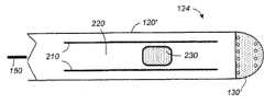
图5显示了根据本发明的优选实施例的具有冲洗电极的导管。Figure 5 shows a catheter with irrigation electrodes according to a preferred embodiment of the present invention.
图6显示了近端附近的导管的横截面图。Figure 6 shows a cross-sectional view of the catheter near the proximal end.
图7显示了根据本发明的优选实施例的位于导管远端的电极的横截面图。Figure 7 shows a cross-sectional view of an electrode at the distal end of a catheter according to a preferred embodiment of the present invention.
图8显示了根据本发明的再一优选实施例的另一冲洗导管。Figure 8 shows another irrigation catheter according to yet another preferred embodiment of the present invention.
图9为对比现有冲洗导管与优选实施例的冲洗导管的消融操作性能的表格。Figure 9 is a table comparing the ablation performance of the conventional irrigation catheter with the irrigation catheter of the preferred embodiment.
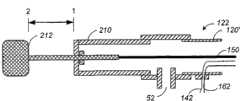
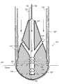
图10A显示了根据本发明的再一优选实施例的冲洗多极导管的远端。Figure 10A shows the distal end of an irrigation multipolar catheter according to yet another preferred embodiment of the present invention.
图10B显示了图10A所示的冲洗多极导管的近端。Figure 10B shows the proximal end of the irrigation multipolar catheter shown in Figure 10A.
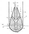
图10C显示了在消融操作中,图10A所示的外周电极被布置为分散展开的二维或三维阵列。FIG. 10C shows that during an ablation operation, the peripheral electrodes shown in FIG. 10A are arranged in a spread out two-dimensional or three-dimensional array.
图11显示了图10A~10C所示冲洗多极导管的尖端电极的优选实施例。Figure 11 shows a preferred embodiment of the tip electrode of the irrigation multipolar catheter shown in Figures 10A-10C.
图12A显示了当外周电极不为分散设置时,冷却剂流管和尖端电极之间的关系。Fig. 12A shows the relationship between the coolant flow tube and the tip electrode when the peripheral electrodes are not dispersed.
图12B显示了当外周电极为如图10C所示的分散设置时,冷却剂流管和尖端电极之间的关系。Figure 12B shows the relationship between the coolant flow tube and the tip electrode when the peripheral electrodes are in a dispersed arrangement as shown in Figure 10C.
图13A显示了多极导管的外周电极的冲洗细节。Figure 13A shows irrigation details of the peripheral electrodes of the multipolar catheter.
图13B显示了自近向的分散设置的外周电极的俯视图。FIG. 13B shows a top view of dispersed peripheral electrodes from the proximal direction.
图14为对比用于治疗心房纤维颤抖的消融过程的不同导管的制定消融操作性能的表格。FIG. 14 is a table comparing the performance of the planned ablation procedure of different catheters used in the ablation procedure for the treatment of atrial fibrillation.
具体实施方式Detailed ways
图1示意性说明了导管消融对心室内的病理组织的典型应用。具体地,图1显示了部分剖面的人心脏10的正面视图。在操作实例中,如图1所示,导管20被经皮引入患者体内,并且通过血管(未标示)指向、进而大动脉19。所述导管具有如置于左心室12内的远端30,所述远端30可以同样容易地被置于右心室14,或者如左心房16或右心房18或另一位点的任何其它心内膜腔室内。Figure 1 schematically illustrates a typical application of catheter ablation to pathological tissue within the ventricle. Specifically, FIG. 1 shows a frontal view of a
导管20具有一个或多个电极。其首先执行标测模式,其中,电极检测到心内膜内的电信号。如US.6,522,905所公开,其公开的全部内容通过引用包含于此,标测操作使导管确定心内膜中心动过速的问题起源位点。一旦问题位点被确定,由于导管的电极经常与外部身体接触电极共同运行,因此导管转向以消融模式操作。射频能被送至电极的组合以消融问题位点。
心室过速(ventricular tachycardia,VT)为一类由于源于心室问题的心律不齐。该疾病包括右心室流出通道心动过速(Right Ventricular Outflow Tract Trachycardia)和心肌缺血性室性心动过速(Ischemic ventricular tachycardia)。类似地,上性心动过速(SVT)是另一类由于源自如心房的上心室问题的心律不齐。该疾病包括心房心动过速(Atrialtachycardia)、AV房室结内折返性心动过速(AV nodal reentrant tachycardia)、预激综合征(wolff-parkinson-white syndrome)、和心房扑动(atrial flutter)。VT和SVT都可以通过消融确定的问题位点或焦点而治愈。心房纤维颤抖(atrial fibrillation)是再一类型的心律不齐。可通过消融确定的焦点或通过消融心房内的损伤线治疗心房纤维颤抖。利用导管消融可以方便地治疗大多数这些疾病,而无需使用损伤性的手术,并且使整个治疗在一天的过程中完成。Ventricular tachycardia (VT) is a type of cardiac arrhythmia due to problems originating in the ventricles. The disorder includes Right Ventricular Outflow Tract Trachycardia and Ischemic ventricular tachycardia. Similarly, superior tachycardia (SVT) is another type of arrhythmia due to problems originating in the upper ventricles such as the atria. The disorders include atrial tachycardia, AV nodal reentrant tachycardia, wolff-parkinson-white syndrome, and atrial flutter. Both VT and SVT can be cured by ablation of an identified problem site or focus. Atrial fibrillation is another type of arrhythmia. Atrial fibrillation can be treated by ablation of a defined focus or by ablation of damaged lines within the atrium. Catheter ablation can be used to treat most of these diseases conveniently, without the use of invasive surgery, and allows the entire treatment to be completed in the course of a single day.
射频能源已成为用于心律不整的导管消融的优选形式。射频发射器输出频率为500~1000kHz的未调制正弦波AC电流。在现有单相消融中,施加的电流是从导管的电极尖端到患者皮肤上的大分散片的单极的。从电极尖端经组织传送至分散片的AC电流引起电阻加热。加热的程度与电流密度的平方成比例。由于消融导管尖端相对于分散片(一般>10cm2)较小,因此,该末端是最高电流密度和加热的点。电流密度随距电极的距离的平方下降;电阻加热因此与距离的四次方成比例下降。这意味着所述电极尖端周围仅产生很小圈(1~1.5mm)的直接电阻加热。Radiofrequency energy has become the preferred form of catheter ablation for cardiac arrhythmias. The RF transmitter outputs an unmodulated sine wave AC current with a frequency of 500-1000kHz. In existing monophasic ablation, the applied current is monopolar from the electrode tip of the catheter to a large dispersed patch on the patient's skin. AC current delivered from the electrode tip through the tissue to the dispersible pad causes resistive heating. The degree of heating is proportional to the square of the current density. Since the tip of the ablation catheter is small relative to the dispersive disc (typically >10 cm2 ), this tip is the point of highest current density and heating. The current density falls with the square of the distance from the electrode; resistive heating therefore falls in proportion to the fourth power of the distance. This means that only a small circle (1-1.5mm) of direct resistive heating occurs around the electrode tip.
已确定,将组织的温度升高至约50摄氏度就足以产生创伤。然而,组织的较深消融取决于来自电阻加热的“有效电极”的传导性加热。因电极尖-组织之间的界面的最高温度,电极尖周围产生大幅的热梯度。通常,电极尖-组织之间的界面随输出功率上升,并且创伤大小与输出功率成比例。It has been determined that raising the temperature of tissue to about 50 degrees Celsius is sufficient to create a wound. However, deeper ablation of tissue depends on conductive heating from resistively heated "active electrodes". A large thermal gradient is created around the electrode tip due to the highest temperature at the electrode tip-tissue interface. In general, the electrode tip-tissue interface rises with output power, and the size of the wound is proportional to output power.
尽管较深和较大的创伤仅能通过提高功率实现,但是,考虑到避免过度加热,从而限制输出功率值。过度加热可以导致在组织内产生蒸汽,最终导致“蒸汽爆裂”,并且导致相邻组织内的潜在的凹陷形成,这可能导致显著的附带损伤、甚至心脏穿孔。Although deeper and larger wounds can only be achieved with increased power, the value of the output power is limited in view of avoiding excessive heating. Excessive heating can lead to steam generation within the tissue, eventually leading to "steam popping" and potential pit formation in adjacent tissue, which can lead to significant collateral damage and even cardiac perforation.
即使在较少过度加热的情况下,如前所述,也有血栓或血块形成的危险。电极周围形成血块可能导致消融电路电阻的突然增加和输出功率的急剧下降。更隐蔽危险的是,一定量的血在电阻的增加应显示凝结之前就开始凝结了。Even with less excessive heating, there is a risk of thrombus or blood clot formation as mentioned earlier. Blood clot formation around the electrodes may cause a sudden increase in the resistance of the ablation circuit and a sharp drop in output power. A more insidious danger is that a certain amount of blood begins to clot before an increase in electrical resistance should indicate clotting.
如前所述,血浆在电极尖-组织界面的沸腾限制了使用标准RF的功率输出。已设计两种增加电极冷却的方法,从而能够维持RF功率的有效水平。第一种方法是增加暴露于血液的电极表面积。因为心室实际上是以每秒约80ml的速率运转的血泵,因此导管在其中运转的血池起将电极向血液的37摄氏度冷却的作用。因此,现有导管装有具4~8mm轴向长度的尖端电极。该较大的表面积增加了对流冷却。特别针对在血流量减少的情况下的问题的第二种方法是以额外引入的冷却剂增加电极冷却,如灌注盐水。盐水灌注使较大的功率输送至组织,并且将最大量的热转送至组织本身。最后,这导致较深的传导热和产生较深的创伤。As mentioned previously, boiling of plasma at the electrode tip-tissue interface limits the power output using standard RF. Two approaches have been devised to increase electrode cooling so that effective levels of RF power can be maintained. The first approach is to increase the electrode surface area exposed to blood. Because the ventricles are actually blood pumps running at a rate of about 80ml per second, the pool of blood in which the catheter runs acts to cool the electrodes to the 37 degrees Celsius of the blood. Therefore, existing catheters are equipped with tip electrodes having an axial length of 4-8 mm. This larger surface area increases convective cooling. A second approach, particularly addressing the problem in cases of reduced blood flow, is to increase electrode cooling with additionally introduced coolant, such as perfusing saline. Saline perfusion delivers greater power to the tissue and transfers the greatest amount of heat to the tissue itself. Ultimately, this results in deeper conductive heat and deeper trauma.
已研发了两类的冲洗导管。第一类是闭合环冲洗导管,其将盐水在电极尖内持续循环,在内部冷却电极尖。第二类是开放的冲洗导管,其冷却剂通过位于电极上的多个冲洗孔、或者通过电极附近的鞘流出导管。这两种冲洗导管的例子已经由Demazumder等在″Comparison of Irrigated Electrode Designs for RadiofrequencyAblation of Myocardium″(Journal of Interventional Cardiac Electrophysiology 5,391-400,2001)中公开。Two types of irrigation catheters have been developed. The first type is a closed loop irrigation catheter, which continuously circulates saline inside the electrode tip, cooling the electrode tip internally. The second type is an open irrigation catheter, where the coolant exits the catheter through multiple irrigation holes located on the electrode, or through a sheath near the electrode. Examples of these two irrigation catheters have been disclosed by Demazumder et al. in "Comparison of Irrigated Electrode Designs for Radiofrequency Ablation of Myocardium" (Journal of Interventional Cardiac Electrophysiology 5, 391-400, 2001).
图2A显示了现有闭合环设计的冲洗导管。尖端电极位于导管的远端。一个尖端电极的例子是直径2.3mm、长5mm的金属罩。腔管将导管内的冷却剂从外部来源(未标示)运送至远端,以冷却电极的内表面。冷却剂通过导管内壁和腔管外壁之间的同心空间所提供的返回通路返回至所述外部来源,从而实现循环。Figure 2A shows the irrigation catheter of the existing closed loop design. The tip electrode is located at the distal end of the catheter. An example of a tip electrode is a metal shield 2.3 mm in diameter and 5 mm long. The lumen carries coolant within the catheter from an external source (not shown) to the distal end to cool the inner surface of the electrode. The coolant is circulated back to the external source through a return path provided by the concentric space between the inner wall of the conduit and the outer wall of the lumen.
图2B显示了现有开放设计的冲洗导管,其中,冷却剂通过位于电极上的孔流出导管。除电极上的冷却剂流出导管的出口数目外,尖端电极与图2A所示相同。在导管内部没有冷却剂返回冷却剂来源的返回通路。Figure 2B shows an irrigation catheter of a prior art open design, where the coolant exits the catheter through holes located on the electrodes. The tip electrode is the same as that shown in Figure 2A except for the number of outlets on the electrode for the coolant outflow conduit. There is no return path for the coolant back to the coolant source inside the conduit.
图2C显示了现有的开放设计的冲洗导管,其中,冷却剂通过电极附近的鞘流出导管。尖端电极与图2A所示的相同。导管的外鞘为从外部来源供给至导管的远端的冷却剂提供了同心空间。所述鞘刚好在具有使冷却剂流出和冲洗电极的开孔的电极之前止于导管的远端。Figure 2C shows an existing open design irrigation catheter in which the coolant exits the catheter through a sheath near the electrodes. The tip electrode is the same as that shown in Figure 2A. The outer sheath of the catheter provides a concentric space for coolant supplied to the distal end of the catheter from an external source. The sheath terminates at the distal end of the catheter just before the electrode with an opening for coolant to flow out and irrigate the electrode.
图3A显示了现有电极周围的传导通道。典型地,对于如图2A~2C所示的现有导管,仅仅之多25%的尖端电极的表面积接触被消融的组织。其它75%暴露于血液以冷却。由于血液的导电性是组织的两倍,因此,绝大部分电流经血液而非组织的传导通路从电极流向接地板(未显示)。Figure 3A shows the conduction channels around the existing electrodes. Typically, with existing catheters as shown in Figures 2A-2C, only at most 25% of the surface area of the tip electrode contacts the tissue being ablated. The other 75% are exposed to blood for cooling. Since blood is twice as conductive as tissue, most of the current flows from the electrodes to the ground plate (not shown) via the conduction path of blood rather than tissue.
图3B示意性显示了图3A所示的现有电极的传导通道的等效电路。所述等效电路具有两个支路,一个支路为从电极至血液的通路,另一支路为从电极至组织的通路。当电极为电压V时,则血液支路产生V=i1R1,其中,i1为血液支路中流动的电流,R1为电阻。同样地,组织支路产生V=i2R2。则由W1=i12R1=i1i2R2得到血液支路的耗能。同样地,由W2=i22R2=i1i2R1得到组织支路的耗能。因此,两个支路的耗能比例为W2/W1=R1/R2。也就是说,各支路的耗能与各支路的电阻成反比。对于电极以1/3的比例暴露于组织和血液、且血液导电性为组织的两倍的情况,W2/W1为1/6。Fig. 3B schematically shows the equivalent circuit of the conduction channel of the conventional electrode shown in Fig. 3A. The equivalent circuit has two branches, one branch is the passage from the electrode to the blood, and the other branch is the passage from the electrode to the tissue. When the voltage of the electrode is V, the blood branch generates V=i1 R1 , where i1 is the current flowing in the blood branch, and R1 is the resistance. Likewise, the tissue branch yields V=i2 R2 . Then, the energy consumption of the blood branch can be obtained from W1 =i12 R1 =i1 i2 R2 . Similarly, the energy consumption of the tissue branch can be obtained from W2 =i22 R2 =i1 i2 R1 . Therefore, the energy consumption ratio of the two branches is W2 /W1 =R1 /R2 . That is to say, the energy consumption of each branch is inversely proportional to the resistance of each branch. For the case where the electrode is exposed to tissue and blood at a ratio of 1/3, and the conductivity of blood is twice that of tissue, W2 /W1 is 1/6.
Wittkampf等在″RF Catheter Ablation:Lessons on Lesions″(PACE,Vol.29,November 2006,pp.1285-1297)中估计在所有供给电极的能量中,约40%的能量损失在患者的其它部分,包括接地电极片附近的区域。其余的60%,仅七分之一被输送至加热组织。这意味着,对于50W的输出功率,仅约9%或约4.5W被用于加热组织。Wittkampf et al estimated in "RF Catheter Ablation: Lessons on Lesions" (PACE, Vol.29, November 2006, pp.1285-1297) that about 40% of the energy lost in all the energy supplied to the electrodes is in other parts of the patient, Include the area near the ground electrode pad. Of the remaining 60%, only one-seventh is delivered to heated tissues. This means that for an output power of 50W, only about 9% or about 4.5W is used to heat the tissue.
Nakagawa等在″Inverse Relationship Between Electrode Size and Lesion SizeDuring Radiofrequency Ablation With Active Electrode Cooling″(Circulation,1998;98;458-465)中通过对比具2mm长的电极的5mm导管的消融特性得到基本相同的发现。然而,尽管发现较短电极是能量更有效的,但是,具有如蒸汽爆裂所示的更多的过热发生。似乎尽管利用冲洗扩大血液的冷却,但是较短电极提供了有效热交换的较小表面积,并且电极易于过度加热。In "Inverse Relationship Between Electrode Size and Lesion Size During Radiofrequency Ablation With Active Electrode Cooling" (Circulation, 1998; 98; 458-465), Nakagawa et al. obtained basically the same finding by comparing the ablation characteristics of a 5mm catheter with a 2mm long electrode. However, although shorter electrodes were found to be more energy efficient, there was more occurrence of overheating as indicated by steam burst. It appears that while the cooling of the blood is extended with irrigation, the shorter electrodes provide less surface area for efficient heat exchange, and the electrodes are prone to overheating.
在任何情况下,在功率在患者的其余部分丢失后,对于每7份输向电极的功率,6份用于通过电极加热血液,仅一份通过电极实际用于加热组织。尽管通过血液冷却,但该不利的功率比对于4~8mm长的现有电极是非常低效率的。现有技术是通过冲洗增加血液冷却电极。然而,且不说在向组织输出更多功率的尝试中易于过度加热电极,也易于引起血块形成。In any case, after power is lost in the rest of the patient, for every 7 parts of power delivered to the electrodes, 6 parts are used to heat blood through the electrodes and only one part is actually used to heat tissue through the electrodes. This unfavorable power ratio is very inefficient for existing electrodes that are 4-8mm long despite cooling by blood. The existing technique is to cool the electrodes by adding blood by flushing. However, not to mention the tendency to overheat the electrodes in an attempt to deliver more power to the tissue, it is also prone to clot formation.
图4为说明现有消融导管和本发明的改进导管的能量体制的图表。作为消融电极暴露于血液的表面积的函数,曲线70(点划线)代表了血液支路的耗能(参见图3B),曲线80(实线)代表了组织支路的耗能。为了方便显示了两个X轴。第一个X轴表示电极暴露于血液的面积逐步增加。第二个X轴表示随组织所覆盖的电极面积逐渐降低的第一X轴的互补。鉴于前述,现有导管典型地以72制运行,其中,供给消融电极的功率不成比例地偏向血液支路。相反,如以下所述,本发明的改进电极设计为以82制运行,其中输送给组织支路的功率被最大化,并且血液支路的耗能被最小化。Figure 4 is a diagram illustrating the energy regime of a conventional ablation catheter and the improved catheter of the present invention. Curve 70 (dashed line) represents energy dissipation in the blood branch (see FIG. 3B ) and curve 80 (solid line) represents energy dissipation in the tissue branch as a function of the surface area of the ablation electrode exposed to blood. Two x-axes are shown for convenience. The first x-axis represents the progressively increasing area of the electrode exposed to blood. The second x-axis represents the complement of the first x-axis with decreasing electrode area covered by tissue. In view of the foregoing, existing catheters typically operate in a 72 regime, where power to the ablation electrodes is disproportionately biased towards the blood branch. In contrast, as described below, the improved electrode of the present invention is designed to operate in 82 mode, where power delivery to the tissue branch is maximized and energy dissipation in the blood branch is minimized.
根据本发明的技术方案,提供了具有改进电极的改进消融导管,所述改进电极提供与组织的最大接触和对血液的最小暴露。该电极置于导管的远端,具有包含在导管内的第一部分和露出导管外的第二部分。用于与导管内的冷却剂热交换的所述第一部分的形状要使其表面积大于第二部分的面积。第二部分的形状为具有伸出的表面,当放置消融生物组织时,所述第二部分基本被生物组织覆盖,并且与生物组织接触,而使未与生物组织接触和未被生物组织覆盖的表面积最小。虽然第二部分具有这种形状,但是电极通过第一部分的构造被充分冷却。同时,冷却剂被用于冲洗电极未被组织覆盖的最小暴露部分,以使血液远离所述最小暴露部分周围的可能的局部热点。According to the technical solution of the present invention, there is provided an improved ablation catheter with improved electrodes that provide maximum contact with tissue and minimum exposure to blood. The electrode is positioned at the distal end of the catheter and has a first portion contained within the catheter and a second portion exposed outside the catheter. Said first portion for heat exchange with the coolant in the conduit is shaped such that its surface area is greater than the area of the second portion. The second portion is shaped to have a protruding surface that, when placed to ablate biological tissue, is substantially covered by and in contact with biological tissue, leaving the portion not in contact with and not covered by biological tissue Surface area is minimal. Although the second part has such a shape, the electrode is sufficiently cooled by the configuration of the first part. At the same time, coolant is used to irrigate the minimally exposed portion of the electrode not covered by tissue in order to keep the blood away from possible local hot spots around said minimally exposed portion.
这样,通过血液的电路通道被最小化,从而产生较少的浪费热,并且能量被有效地用于加热组织。由于较少的浪费功率通过电极倾卸,因此,冷却电极的需要较少。更重要地,尽管电极的第二部分被减少暴露,但是电极仍然在第一部分处被充分冷却。此外,在此方式中,冷却剂在未被遮蔽的第二部分处流出,从而不利于血块形成。各种措施使消融时间至少缩短了两倍,并且流出的冷却剂的量至少减少了十倍,血块形成的危险被最小化。In this way, circuit passage through the blood is minimized, so less wasted heat is generated, and energy is efficiently used to heat tissue. Since less wasted power is dumped through the electrodes, there is less need to cool the electrodes. More importantly, despite the reduced exposure of the second portion of the electrode, the electrode is still sufficiently cooled at the first portion. Furthermore, in this manner, the coolant flows out at the second portion which is not shielded, thus detrimental to clot formation. Various measures shorten the ablation time by at least two times, and the amount of outflowing coolant is reduced by at least ten times, and the risk of blood clot formation is minimized.
在优选实施例中,电极长2mm或更短,从而在消融过程中,即使不是全部、其大部分也都埋入、且被组织覆盖。在操作中,使电极与组织垂直,以实现被组织的最大覆盖。对于电极未被组织覆盖的任何暴露部分,其与血液的接触由附近流出的冷却剂保护。这样,使血液远离电极附件的任何热点。In a preferred embodiment, the electrodes are 2 mm long or less so that most, if not all, of them are buried and covered by tissue during ablation. In operation, the electrodes are positioned perpendicular to the tissue to achieve maximum coverage of the tissue. Any exposed portion of the electrode not covered by tissue is protected from contact with blood by coolant flowing nearby. This keeps the blood away from any hot spots near the electrodes.
图5显示了根据本发明的优选实施例的具有冲洗电极的导管。导管100具有延长套120,所述延长套120具有近端122和远端124。电极130形成位于远端的尖端电极。在近端,导管以手柄110终止。在近端,电连接实现与外部消融和标测控制系统50连接。并且,液体端口使冷却剂由冷却剂源60供给至导管内。Figure 5 shows a catheter with irrigation electrodes according to a preferred embodiment of the present invention.
图6显示了近端附近的导管的横截面图。延长套120具有内室,所述内室使如电线142和162的电导体从远端进入、从近端122处引出。近手柄110的位于近端122处的液体端口52使冷却剂送入延长套120的内室。Figure 6 shows a cross-sectional view of the catheter near the proximal end.
图7显示了根据本发明的优选实施例的导管的远端处电极的横截面图。电极130为位于导管远端124的尖部的导电体。在优选实施例中,其具有梨形体,所述梨形体的一端为穹形部分,相对端为锥形部分。电极130置于延长套120的远端,从而所述锥形部分被包括在所述延长套的内部,而所述穹形部分露在导管的外面。这样,电极130被分割为两部分,导管内的第一部分132和导管外的第二部分134。Figure 7 shows a cross-sectional view of an electrode at the distal end of a catheter according to a preferred embodiment of the present invention.
在消融过程中,例如,将导管置于充满血液的心室内。在外部的电极的第二部分134的表面和形状使其在心内膜中消融组织时具有与组织表面80接触的表面、并且该表面基本被组织覆盖。在多数情况下,几乎整个第二部分都被组织覆盖。至多,第二部分的最小未被覆盖面积136(不超过第二部分的表面积的35%)没有被组织覆盖而暴露于血液。第二部分134的优选形状为直径为2.3mm、高1.5~2mm的穹形。During ablation, for example, a catheter is placed inside a blood-filled ventricle. The surface and shape of the
电极置于导管内的第一部分132优选为延长锥形,该形状使其表面积基本大于第二部分134的表面积,以提供与冷却剂热交换的足够面积。只要足够的面积适于热交换,则其它形状的第一部分也是可能的。The
电极130优选为具有良好导热性的实心体。这与其延长体形状共同提供了较现有中空鞘电极更好的热容性,从而实现电极-组织界面处的更好的温度控制。The
电极130在其体内具有通道140。所述通道140具有位于所述第一部分132的表面的入口、和位于所述第二部分134的表面的出口。通过近端提供到延长套内的冷却剂经如入口142、144的入口沿所述通道导入电极体130内,并且经第二部分134的表面上如出口146、148的出口被排出。实际中,冷却剂刚好在接触需消融的组织之前流经。这样,从出口148排出的冷却剂有助于清理电极-组织界面的血液,以及在电极-组织界面处提供导电介质。具体地,出口146位于在与第一部分132之间边界附件的第二部分134上的区域136内。如前所述,在消融过程中,电极的第二部分的区域136可能未被组织覆盖而暴露于血液。通过位于区域136内的出口146,排出的冷却剂有助于使血液远离未覆盖区域136,以防止血液在任何热点附件凝结。这将进一步减少血块的形成。The
图8显示了根据本发明另一优选实施例的另一冲洗导管。除区域136附近的出口146被位于电极的第一部分132和第二部分134之间的边界处的圆孔146’所替代外,该构造与图7所述类似。因此,冷却剂经如入口142、144的入口经通道导入电极体130内,并且经如出口146’和148的出口排出。Fig. 8 shows another irrigation catheter according to another preferred embodiment of the present invention. The configuration is similar to that described for Figure 7, except that the
图9为对比现有冲洗导管与优选实施例的冲洗导管的消融操作性能的表格。标准电极的结果汇编自公开数据、以及在实验室中对生物组织进行的实验。改进电极的结果也来自实验室中对生物组织进行的实验。Figure 9 is a table comparing the ablation performance of the conventional irrigation catheter with the irrigation catheter of the preferred embodiment. Results for standard electrodes were compiled from published data, as well as experiments performed on biological tissue in the laboratory. The results of improved electrodes also come from experiments on biological tissue in the laboratory.
由图9(A)可知,“标准电极”的电极尺寸典型为“改进冲洗电极”的双倍长度。额外的长度提供了更多由血液冷却的面积。图9(B)显示了在典型的实践中,至多25%的标准电极与需被消融的组织接触,剩余75%的电极表面暴露于用于冷却的血液。另一方面,典型地,改进导管的暴露电极表面的大部分都与组织接触,只有相对较小部分未被组织覆盖。图9(C)显示标准电极被37℃的血液冷却,并且冷却可能通过以20℃(2的盐水冲洗冷却而放大。另一方面,所述改进电极仅使用盐水冷却电极的延伸表面。电极的延伸表面在图7中显示为电极130的第一部分132,并且未暴露于血液。It can be seen from Fig. 9(A) that the electrode size of the "standard electrode" is typically double the length of the "improved flushing electrode". The extra length provides more area to be cooled by the blood. Figure 9(B) shows that in typical practice, up to 25% of the standard electrode is in contact with the tissue to be ablated, leaving the remaining 75% of the electrode surface exposed to blood for cooling. On the other hand, typically, the majority of the exposed electrode surface of the improved catheter is in contact with tissue, with only a relatively small portion uncovered by tissue. Figure 9(C) shows that the standard electrode is cooled by blood at 37°C, and the cooling may be amplified by flushing cooling with saline at 20°C (2). On the other hand, the improved electrode uses only saline to cool the extended surface of the electrode. The electrode's The extended surface is shown in FIG. 7 as the
图9(D)显示调控在相同温度范围内操作两个电极,所述温度范围优选为适于创伤产生、而无太多的副作用。图9(E)显示设定各个导管的操作条件,以产生相同大小的创伤。在此方面,由图9(F)可以看出,产生相同大小的创伤,改进电极需要约一半的功率(典型的为15W)。此外,由图9(G),形成创伤的时间为标准电极的一半。并且,改进电极的冷却是非常有效的,与标准电极相比,所需少了一个数量级体积的盐水量,却仍然实现较好的冷却。通过实际报告证明,在相同条件下,当利用此标准电极消融时,具有水蒸气爆裂的过度加热确实偶尔发生。如图9(I)所总结,由于有效功率利用和较好冷却,对于改进电极,蒸汽爆裂的风险确实非常低。最后,图9(J)总结了改进电极的另一优点,所述优点为由于电极未被组织覆盖的部分被最小化、且血液通过此处流出的冷却剂而远离未覆盖部分,因此,与现有电极相比,改进电极的血块形成的风险被显著降低。由于血液与电极未被覆盖的部分保持一定距离,因此,血液电路的横截面被扩大,从而得到较低浓度的功率消耗和加热。Figure 9(D) shows regulation to operate both electrodes in the same temperature range, which is preferably suitable for wound generation without too many side effects. FIG. 9(E) shows that the operating conditions of each catheter were set to produce lesions of the same size. In this regard, it can be seen from FIG. 9(F) that the modified electrode requires about half the power (typically 15W) to produce the same size of wound. Furthermore, from FIG. 9(G), the time to form a lesion is half that of the standard electrode. Also, the improved cooling of the electrodes is very effective, requiring an order of magnitude less volume of brine than standard electrodes to still achieve better cooling. It has been demonstrated by actual reports that, under the same conditions, when ablated with this standard electrode, superheating with water vapor burst does occasionally occur. As summarized in Figure 9(I), the risk of steam popping is indeed very low for the improved electrode due to efficient power utilization and better cooling. Finally, Fig. 9(J) summarizes another advantage of the improved electrode, which is that since the portion of the electrode uncovered by tissue is minimized and the blood is kept away from the uncovered portion by the coolant flowing out there, it is, in contrast to The risk of blood clot formation is significantly reduced with the improved electrodes compared to existing electrodes. Since the blood is kept at a distance from the uncovered parts of the electrodes, the cross-section of the blood circuit is enlarged, resulting in lower concentrations of power consumption and heating.
如图9所示,图7和图8所述的消融电极有利于有效、快速、以最小血块形成风险产生大小合理的创伤。在操作中,导管的远端优选以垂直方向接触组织,以确保组织对电极的最大覆盖。As shown in Figure 9, the ablation electrode described in Figures 7 and 8 facilitates effective, rapid generation of reasonably sized lesions with minimal risk of clot formation. In operation, the distal end of the catheter preferably contacts the tissue in a perpendicular orientation to ensure maximum tissue coverage of the electrodes.
根据本发明的另一技术方案,即使在一个过程中需要较大的创伤或平行产生多个创伤时,本发明的技术特征以跨越较大消融区域的改进多极导管被实施。各个电极包括本发明的特征。包含本发明的特征的适合的多电极导管与US 6,738,673所公开的类似,通过引用包含其全部内容。According to another technical solution of the present invention, the technical features of the present invention are implemented in an improved multipolar catheter that spans a large ablation area even when a larger wound is required in one procedure or multiple wounds are created in parallel. Each electrode includes features of the invention. A suitable multi-electrode catheter incorporating features of the present invention is similar to that disclosed in US 6,738,673, the entire content of which is incorporated by reference.
图10A显示了根据本发明的另一优选实施例的冲洗多极导管的远端。除电极130’外,延长套120’的远端具有多个外周电极230。一个例子为四个外周电极230,所述外周电极230在以距尖端电极130’预定距离处、绕延长套120’的圆周等间距。这样,导管包括多个电极230和位于中心的电极130’。当导管被引入患者体内时,电极能够落到导管主体上。Figure 10A shows the distal end of an irrigation multipolar catheter according to another preferred embodiment of the present invention. In addition to electrodes 130', the distal end of extension sheath 120' has a plurality of
图10B显示了图10A所示的冲洗多极导管的近端。除其在手柄210处包括传动装置212,该构造与图6所示类似。所述传动装置212通过硬电缆150与尖端电极机械连接。Figure 10B shows the proximal end of the irrigation multipolar catheter shown in Figure 10A. The construction is similar to that shown in FIG. 6 except that it includes a
图10C显示在消融操作过程中,图10A所示外周电极以分散布置为二维或三维阵列。四个外周电极可控地处于收缩或崩落模式。当分散时,四个外周电极和中心电极形成典型地覆盖约0.8cm2面积的电极阵列。当与背板联合利用现有RF能源时,五个连接电极会典型地同时产生5个分布在电极阵列所跨区域的创伤点。FIG. 10C shows the peripheral electrodes shown in FIG. 10A in a dispersed arrangement as a two-dimensional or three-dimensional array during an ablation procedure. The four peripheral electrodes are controllably in collapsed or collapsed mode. When dispersed, the four peripheral electrodes and the central electrode form an electrode array that typically covers an area of about 0.8cm2 . When used in conjunction with a backplate utilizing existing RF energy, five connected electrodes would typically simultaneously create five wound sites distributed across the area spanned by the electrode array.
优选的实施方式是所述延长套由可变形材料制成。外周电极230本身可以方便地如黄金或白金的高导电性材料制成。其性状和构造提供了与需消融组织的最大接触和包被。从与尖端电极130’相邻的点至距远端预定距离处切割贯通所述延长套120的多个纵向缝隙210。例如,对于外周电极和中心电极之间的1cm距离,该预定距离约为2~2.5厘米。也要考虑分散模式中外周电极和中心电极之间的其它相互电极间距离。并且,外周电极的其它数目也需考虑。所述缝隙在其间限定并形成了中间带220。延长套120’本身的外径易为约2.34mm。也参考图10B,当传动装置212在第一位置(1)时,线150与尖端电极130’一起朝远端被充分拉伸,结果如图10A所示,使外周电极崩落到延长套120’的未变形的面上。当传动装置212处于第二位置(2)时,线150的轴与尖端电极130’一起向近端收缩预定的量,结果使细缝210处的延长套变形。带220打开,并以外周电极230与其中心处的尖端电极130’处于同一平面的方式升高外周电极230,使其离开延长体120’的轴。A preferred embodiment is that the extension sleeve is made of deformable material. The
图11显示了图10A~10C所示冲洗多极导管的尖端电极的优选实施例。除其还具有连接尖端电极130’和传动装置212的线150之外,尖端电极130’与图7所示的基本相同。并且,由于延长套120由于细缝210而不再是液体密闭的,因此,液体管170提供具有冷却剂端口52的液体密闭线路(参见图10B),并且防止通过细缝渗漏。液体管具有无论传动装置212和尖端电极130’处于任何位置都使其保持密闭液体连通的纬度。Figure 11 shows a preferred embodiment of the tip electrode of the irrigation multipolar catheter shown in Figures 10A-10C. The tip electrode 130' is substantially the same as that shown in FIG. 7, except that it also has a
在操作例中,如图1所示,近端的传动装置212处于位置1,具有松开的外周电极的导管100被垂直引入患者体内,并且通过血管(图中为标注)引向进入大动脉19。然后远端124定位至心内膜壁。然后传动装置212移向位置2。这使尖端电极130’由其第一位置向近端收缩,使外周电极230如图10C所示分散。在该位置,多个外周电极230距其中心处的电极130’、以大于第一距离的第二距离等距设置。相邻外周电极之间的距离易为约1cm。这样,约1cm2面积的心内膜壁在cm2的中心处覆盖电极130’。可以理解,外周电极230位于细缝210所形成的带的上半部上,从而使电极朝向远端方向。各个外周电极分别与电导线之一连接,所述电导线在近端从导管引出。In the operational example, as shown in FIG. 1 , the
图12A和图12B分别显示了,当外周电极没有分散设置、而以根据本发明的再一优选实施例被分散设置时的冷却剂液体连通的细节。在该优选实施例中,液体管170提供了具有冷却剂端口52的液体密闭线路。FIG. 12A and FIG. 12B respectively show the details of the coolant liquid communication when the peripheral electrodes are not distributed but are distributed according to yet another preferred embodiment of the present invention. In the preferred embodiment,
图12A显示了外周电极不为以分散构造时的冷却剂液体管和尖端电极之间的关系。当外周电极230不为分散构造时,在远端,则液体管偏移、且脱离尖端电极的第一部分132。Figure 12A shows the relationship between the coolant liquid tube and the tip electrode when the peripheral electrode is not in a dispersed configuration. When the
图12B显示了当外周电极如图10C所示分散设置时的冷却剂流体管与尖端电极之间的关系。在远端,尖端电极130’向开放的流体管撤回,从而所述电极130’的第一部分132被完全封入由流体管的通道所提供的接收器172内。这样,当处于分散位置时,流体可以冷却尖端电极130’的第二部分132,而无泄露、并且不使第二部分132暴露于附近的任何血液。FIG. 12B shows the relationship between the coolant fluid tube and the tip electrode when the peripheral electrodes are distributed as shown in FIG. 10C. At the distal end, the tip electrode 130' is withdrawn towards the open fluid tube such that the
图13A显示了多极导管的外周电极的冲洗细节。冲洗通道242被提供给各外周电极230,所述冲洗通道242起将冷却剂从流体管170输送到各个外周电极230的支路通道作用。各个冲洗通道242延各个中间带220延伸到封装外周电极230的腔244。Figure 13A shows irrigation details of the peripheral electrodes of the multipolar catheter. An irrigation channel 242 is provided to each
图13B显示了自远向的分散设置的外周电极的俯视图。在与外周电极230相邻的中间带220上具有冲洗出口246。电极230上也提供了出口248,以使冷却剂从腔244排出电极外。Fig. 13B shows a top view of the dispersed peripheral electrodes from the distal direction. There is an irrigation outlet 246 on the
根据本发明的另一技术方案,优选改进电极装入具有分散侧翼的导管中,所述分散的侧翼与中心处的电极形成平面。这样,当导管接触组织时,所述平面就紧紧吸附组织表面,并且电极以垂直方向入侵组织。如图10A和10C所示的中间带220就起侧翼作用。According to another technical solution of the present invention, it is preferred that the improved electrode is incorporated into a catheter with divergent wings forming a plane with the electrode at the center. Thus, when the catheter touches the tissue, the planes adhere tightly to the tissue surface and the electrodes invade the tissue in a perpendicular direction. The
如图10~13所示的改进多极导管极大改善了涉及多消融操作的程序的性能和安全性。The improved multipolar catheter shown in Figures 10-13 greatly improves the performance and safety of procedures involving multiple ablation procedures.
最普遍的心动过速之一为心房纤维颤抖(atrial fibrillation)。这是患者数最多的持续性症状心律不齐,在美国有250万、在全世界有超过5百万的患者。基于最近的人口研究,该数目在以后的数十年还会翻四倍。该问题的严重性已由其完善描述的如导致中风的血栓栓塞、充血性心力衰竭、认知功能障碍的临床结果及可能增加死亡率引起关注。该问题的重要性已由一般人群中对治疗心房纤维颤抖的需求的负担而被重视,该负担给健康保健体系施加了重压。在超过65岁的老年人群中,5.8%患心房纤维颤抖,其已占住院治疗人群的11%;30%患有冠心病的患者,30~40%患有心脏病的患者具有这种心律不齐。根据心脏研究(Framingham Study),每四个人中就有一个人在其生命过程中可能出现这种心律不齐。One of the most common tachycardias is atrial fibrillation. It is the most populous persistent symptomatic arrhythmia, affecting 2.5 million people in the United States and more than 5 million people worldwide. Based on recent population studies, that number will quadruple in the next few decades. The magnitude of this problem has drawn attention from its well-described clinical outcomes such as thromboembolism leading to stroke, congestive heart failure, cognitive impairment, and possible increased mortality. The importance of this problem has been underscored by the burden of need to treat atrial fibrillation in the general population, which places a heavy strain on the health care system. Among the elderly over 65 years old, 5.8% suffer from atrial fibrillation, which accounts for 11% of the hospitalized population; 30% of patients with coronary heart disease, 30-40% of patients with heart disease have this arrhythmia together. According to the Framingham Study, as many as one in four people may experience this irregular heartbeat during their lifetime.
在大多数患者中,标准抗心律不齐治疗是不能恢复正常窦性心律(normal sinusrhythm,NSR)。在过去10年中,这种心律不齐的射频导管消融一直被发展,并且已取得显著的进步。该心律不齐的来源推定为左心房的四个肺静脉或围绕其。通过包括仅解剖环肺静脉线性消融治疗慢性心房颤动(Pulmonary Vein Antrum IsolationPVAI)、共用引发剂的电绝缘、基底修饰的各种技术及这些技术的组合实施心律不齐的导管消融。Standard antiarrhythmic therapy fails to restore normal sinus rhythm (NSR) in most patients. Radiofrequency catheter ablation of such arrhythmias has been developed over the past 10 years and has made remarkable progress. The source of this arrhythmia was presumed to be the four pulmonary veins in or around the left atrium. Catheter ablation of cardiac arrhythmias is performed by various techniques including linear ablation of only anatomically circumscribed pulmonary veins for chronic atrial fibrillation (Pulmonary Vein Antrum IsolationPVAI), electrical isolation of shared initiators, substrate modification, and combinations of these techniques.
作为最常用的实践,通过经双十字通路在左心房中插入环形标测导管和标准的3.5mm冲洗融合导管进行所述治疗。放置额外的导管进行标测和步测冠状窦、希氏束(His bundle)、右心房及右心室。在左心房,围绕四个肺静脉及在左心房的后壁实施40~60个射频消融。在各个消融过程中,35~50瓦特的功率在40~50摄氏度下通过温控射频发生器被输出。在各个消融过程中使用的盐水冲洗液体为30mL/min。整个过程所需时间大于3小时,并且,包括标测和定位电极时间的全部过程中所使用的总液体大于3000mL或3升。如上所述,这样的易感患者由于显著的流体负担(在5L的总血量中注入3L盐水)而易于心衰竭。标准冲洗导管所使用的40~50瓦的高功率、及其大面积暴露于血液具有产生并发症的潜在危险,所述并发症如血栓栓塞、食管受伤、心包积液(pericardial effusion)和心压塞。左心房为3-4mm厚的薄壁结构。食管刚好位于左心房后壁的后面,并且来自左心房的心外壁,厚度约为3~4mm。食管损伤是非常严重的并发症,并且目前有1%的经受标准消融治疗的患者发生食管损伤。一个最近的研究显示6~36%患者有无症状的食道溃疡。As the most common practice, the treatment is performed by inserting a circular mapping catheter and a standard 3.5 mm irrigation fusion catheter in the left atrium via a double cross access. Additional catheters were placed for mapping and pacing of the coronary sinus, His bundle, right atrium, and right ventricle. In the left atrium, 40 to 60 radiofrequency ablation sessions were performed around the four pulmonary veins and on the posterior wall of the left atrium. During each ablation procedure, 35-50 watts of power were delivered by a temperature-controlled RF generator at 40-50 degrees Celsius. A saline flush of 30 mL/min was used during each ablation session. The time required for the entire process was greater than 3 hours, and the total fluid used in the entire process, including the time for mapping and positioning the electrodes, was greater than 3000 mL or 3 liters. As noted above, such susceptible patients are prone to heart failure due to the significant fluid burden (3 L of saline for a total blood volume of 5 L). The high power of 40 to 50 watts used in standard irrigation catheters and their extensive exposure to blood has the potential for complications such as thromboembolism, esophageal injury, pericardial effusion, and cardiac pressure stuffed. The left atrium is a thin-walled structure 3-4mm thick. The esophagus is located just behind the posterior wall of the left atrium and comes from the outer wall of the left atrium, with a thickness of about 3 to 4 mm. Esophageal injury is a very serious complication and currently occurs in 1% of patients undergoing standard ablation therapy. A recent study showed that 6 to 36% of patients had asymptomatic esophageal ulcers.
在各种研究中,目前,心房纤维颤抖的射频导管消融实践已达65%~85%的成功率。目前的技术是高科技、高要求的,并且仅由少部分具有大量实践案例的专业中心里的熟练、经验丰富的电生理医生才能操作该技术。这些中心的排队治疗时间平均为18~24个月。这种较长的耽搁直接关系到如大于3小时的操作时间、以及可能导致严重并发症的许多复杂情况的目前标准射频消融导管技术的难题。In various studies, radiofrequency catheter ablation of atrial fibrillation is currently practiced with a success rate of 65% to 85%. The current technique is high-tech, demanding, and performed only by a small number of skilled, experienced electrophysiologists in specialized centers with extensive practice. The average waiting time for treatment in these centers is 18 to 24 months. This long delay is directly related to the difficulties of current standard radiofrequency ablation catheter techniques such as > 3 hours procedure time, and many complications that can lead to serious complications.
本发明的改进消融导管极大改善了该程序的性能和安全性。这种改进导管将操作时间降低至不到1小时,将操作过程中灌注到患者体内的液体从3000mL降至2000mL,将每个消融的40~50w功率降低至15w,并且将所有严重的并发症降至最低、使心房纤维颤抖的射频消融对于所用电生理医生都简单、通用。The improved ablation catheter of the present invention greatly improves the performance and safety of this procedure. This improved catheter reduces the operation time to less than 1 hour, reduces the fluid infused into the patient from 3000mL to 2000mL during the operation, reduces the power of 40~50w per ablation to 15w, and reduces all serious complications Radiofrequency ablation to minimize atrial fibrillation is simple and common to all electrophysiologists.
图14为对比用于治疗房颤的消融过程的不同导管的制定消融操作特性的表格。被比较的导管为:1)具有标准电极的导管;2)具有如图7、图8所示改进电极的导管;3)具有如图10~13所示改进多电极的导管。对比是按照用于治疗心房纤维颤抖的如5位点的多位点消融的实际操作所需要求和条件而指定。标准电极和改进电极之间的对比在之前一个位点消融的实例中已给出。Figure 14 is a table comparing the established ablation performance characteristics of different catheters used in the ablation procedure for the treatment of atrial fibrillation. The catheters being compared were: 1) catheters with standard electrodes; 2) catheters with modified electrodes as shown in Figures 7 and 8; 3) catheters with modified multi-electrodes as shown in Figures 10-13. Contrasts are specified in accordance with practical requirements and conditions for multi-site ablation such as 5 sites for the treatment of atrial fibrillation. A comparison between standard and modified electrodes was given in the previous example of site ablation.
图14(A)和14(B)分别说明对于三个导管,产生大小相同的创伤所需RF功率和实施时间。图14(C)显示,对于治疗心房纤维颤抖,对于单电极,典型的40~60位点需要被消融。对于5电极的导管,需消融的位点数目为8~12个。Figures 14(A) and 14(B) illustrate the RF power and delivery time required to produce lesions of the same size for three catheters, respectively. Figure 14(C) shows that for the treatment of atrial fibrillation, typically 40-60 sites need to be ablated for a single electrode. For a 5-electrode catheter, the number of sites to be ablated ranges from 8 to 12.
在各个消融之前,导管必须被调遣至需被消融的位点。这种调遣经常通过标测引导。在标准的操作中,通过另一标测导管实施标测。一旦标测导管已确定了位点,然后消融导管就被定位至此位点。图14(D)列出了消融和标测所需的总时间。参考图9所示数据,60个位点的消融时间约为一小时,通过标测引导的复位还需1小时的时间。除消融时间减半至1.5小时外,具改进电极的导管是类似的。由于5个位点平行消融,因此,多极导管所需时间更短,并且复位的时间也相应减少。Before each ablation, a catheter must be deployed to the site to be ablated. Such maneuvers are often guided by mapping. In standard practice, mapping is performed through another mapping catheter. Once the mapping catheter has been sited, the ablation catheter is then positioned to that site. Figure 14(D) lists the total time required for ablation and mapping. Referring to the data shown in Figure 9, the ablation time of 60 sites is about one hour, and the reset guided by mapping will take another one hour. The catheter with the modified electrodes was similar except that the ablation time was halved to 1.5 hours. Since 5 sites are ablated in parallel, the multipolar catheter requires less time and the time to reposition is reduced accordingly.
图14(E)对比了在操作过程中灌注到患者血液系统中的冷却剂的量。众所周知,使用标准导管操作该程序需要向患者的血液系统中灌注3000mL的冷却剂。相对比,本发明的具有单一改进电极或多个改进电极的改进导管仅释放少一个数量级的冷却剂。Figure 14(E) compares the amount of coolant perfused into the patient's blood system during operation. It is well known that performing this procedure using a standard catheter requires infusing 3000 mL of coolant into the patient's blood system. In comparison, the improved catheters of the present invention having a single modified electrode or multiple modified electrodes release only an order of magnitude less coolant.
图14(F)显示为了监测创伤的质量还需要标测。通过显著衰减的心电图表示好的创伤。Figure 14(F) shows that mapping is also required in order to monitor the quality of the wound. Good trauma is indicated by a markedly attenuated ECG.
图14(G)与图9(I)类似。由于有效的功率利用和较好冷却,对于改进电极,蒸汽爆破的风险是极低的。Fig. 14(G) is similar to Fig. 9(I). Due to efficient power utilization and better cooling, the risk of steam explosion is extremely low for the improved electrodes.
最后,图14(H)与图9(J)类似。改进电极的另一优点为,由于电极未被组织覆盖的部分被最小化,且血液通过此处流出的冷却剂而远离未覆盖部分,因此,与现有电极相比,改进电极的血块形成的风险被显著降低。Finally, Figure 14(H) is similar to Figure 9(J). Another advantage of the improved electrode is that the improved electrode's resistance to clot formation compared to existing electrodes is due to the minimized portion of the electrode not covered by tissue and the flow of blood away from the uncovered portion by the coolant flowing there. Risk is significantly reduced.
尽管已描述的本发明的各种技术方案的实施例为优选实施方式,但是,本领域普通技术人员可以理解,其各种变化也是可能的。此处所描述的设备和方法适于通常的生物组织的消融。因此,本发明应授予在所附权利要求的完整范围内保护。Although the described embodiments of various technical solutions of the present invention are preferred implementations, those skilled in the art will understand that various changes are also possible. The devices and methods described herein are suitable for ablation of biological tissue in general. Accordingly, the invention is entitled to protection within the full scope of the appended claims.
Claims (9)
Translated fromChinesePriority Applications (1)
| Application Number | Priority Date | Filing Date | Title |
|---|---|---|---|
| CN201310403922.2ACN103462687B (en) | 2008-07-15 | 2009-07-08 | For improvement of the conduit melting and method |
Applications Claiming Priority (3)
| Application Number | Priority Date | Filing Date | Title |
|---|---|---|---|
| US12/173,794 | 2008-07-15 | ||
| US12/173,794US8882761B2 (en) | 2008-07-15 | 2008-07-15 | Catheter and method for improved ablation |
| PCT/US2009/049877WO2010008975A2 (en) | 2008-07-15 | 2009-07-08 | Catheter and method for improved ablation |
Related Child Applications (1)
| Application Number | Title | Priority Date | Filing Date |
|---|---|---|---|
| CN201310403922.2ADivisionCN103462687B (en) | 2008-07-15 | 2009-07-08 | For improvement of the conduit melting and method |
Publications (2)
| Publication Number | Publication Date |
|---|---|
| CN102119009A CN102119009A (en) | 2011-07-06 |
| CN102119009Btrue CN102119009B (en) | 2013-09-11 |
Family
ID=41258832
Family Applications (2)
| Application Number | Title | Priority Date | Filing Date |
|---|---|---|---|
| CN201310403922.2AExpired - Fee RelatedCN103462687B (en) | 2008-07-15 | 2009-07-08 | For improvement of the conduit melting and method |
| CN2009801280365AExpired - Fee RelatedCN102119009B (en) | 2008-07-15 | 2009-07-08 | Catheter and method for improved ablation |
Family Applications Before (1)
| Application Number | Title | Priority Date | Filing Date |
|---|---|---|---|
| CN201310403922.2AExpired - Fee RelatedCN103462687B (en) | 2008-07-15 | 2009-07-08 | For improvement of the conduit melting and method |
Country Status (6)
| Country | Link |
|---|---|
| US (4) | US8882761B2 (en) |
| EP (2) | EP3308732B1 (en) |
| JP (1) | JP5770628B2 (en) |
| CN (2) | CN103462687B (en) |
| CA (1) | CA2730625C (en) |
| WO (1) | WO2010008975A2 (en) |
Families Citing this family (71)
| Publication number | Priority date | Publication date | Assignee | Title |
|---|---|---|---|---|
| US10492729B2 (en) | 2007-05-23 | 2019-12-03 | St. Jude Medical, Cardiology Division, Inc. | Flexible high-density mapping catheter tips and flexible ablation catheter tips with onboard high-density mapping electrodes |
| US8437832B2 (en) | 2008-06-06 | 2013-05-07 | Biosense Webster, Inc. | Catheter with bendable tip |
| US8882761B2 (en)* | 2008-07-15 | 2014-11-11 | Catheffects, Inc. | Catheter and method for improved ablation |
| US9101734B2 (en) | 2008-09-09 | 2015-08-11 | Biosense Webster, Inc. | Force-sensing catheter with bonded center strut |
| US9795442B2 (en)* | 2008-11-11 | 2017-10-24 | Shifamed Holdings, Llc | Ablation catheters |
| US8600472B2 (en) | 2008-12-30 | 2013-12-03 | Biosense Webster (Israel), Ltd. | Dual-purpose lasso catheter with irrigation using circumferentially arranged ring bump electrodes |
| US8475450B2 (en)* | 2008-12-30 | 2013-07-02 | Biosense Webster, Inc. | Dual-purpose lasso catheter with irrigation |
| US9226791B2 (en) | 2012-03-12 | 2016-01-05 | Advanced Cardiac Therapeutics, Inc. | Systems for temperature-controlled ablation using radiometric feedback |
| US8954161B2 (en) | 2012-06-01 | 2015-02-10 | Advanced Cardiac Therapeutics, Inc. | Systems and methods for radiometrically measuring temperature and detecting tissue contact prior to and during tissue ablation |
| US8926605B2 (en) | 2012-02-07 | 2015-01-06 | Advanced Cardiac Therapeutics, Inc. | Systems and methods for radiometrically measuring temperature during tissue ablation |
| US9277961B2 (en) | 2009-06-12 | 2016-03-08 | Advanced Cardiac Therapeutics, Inc. | Systems and methods of radiometrically determining a hot-spot temperature of tissue being treated |
| US10688278B2 (en) | 2009-11-30 | 2020-06-23 | Biosense Webster (Israel), Ltd. | Catheter with pressure measuring tip |
| US8374670B2 (en) | 2010-01-22 | 2013-02-12 | Biosense Webster, Inc. | Catheter having a force sensing distal tip |
| US9265574B2 (en)* | 2010-03-10 | 2016-02-23 | Biosense Webster (Israel) Ltd. | Monitoring tissue temperature while using an irrigated catheter |
| US9980772B2 (en) | 2010-03-10 | 2018-05-29 | Biosense Webster (Israel) Ltd. | Monitoring tissue temperature while using an irrigated catheter |
| US20140171806A1 (en)* | 2012-12-17 | 2014-06-19 | Biosense Webster (Israel), Ltd. | Optical lesion assessment |
| US11490957B2 (en) | 2010-06-16 | 2022-11-08 | Biosense Webster (Israel) Ltd. | Spectral sensing of ablation |
| US10314650B2 (en) | 2010-06-16 | 2019-06-11 | Biosense Webster (Israel) Ltd. | Spectral sensing of ablation |
| US8226580B2 (en) | 2010-06-30 | 2012-07-24 | Biosense Webster (Israel), Ltd. | Pressure sensing for a multi-arm catheter |
| US8380276B2 (en) | 2010-08-16 | 2013-02-19 | Biosense Webster, Inc. | Catheter with thin film pressure sensing distal tip |
| US10405920B2 (en) | 2016-01-25 | 2019-09-10 | Biosense Webster (Israel) Ltd. | Temperature controlled short duration ablation |
| US10441354B2 (en) | 2016-01-25 | 2019-10-15 | Biosense Webster (Israel) Ltd. | Temperature controlled short duration ablation |
| US10292763B2 (en) | 2016-01-25 | 2019-05-21 | Biosense Webster (Israel) Ltd. | Temperature controlled short duration ablation |
| AU2012202857B2 (en)* | 2011-05-23 | 2014-10-30 | Biosense Webster (Israel), Ltd. | Monitoring tissue temperature while using an irrigated catheter |
| US9220433B2 (en) | 2011-06-30 | 2015-12-29 | Biosense Webster (Israel), Ltd. | Catheter with variable arcuate distal section |
| US9662169B2 (en) | 2011-07-30 | 2017-05-30 | Biosense Webster (Israel) Ltd. | Catheter with flow balancing valve |
| JP6441679B2 (en) | 2011-12-09 | 2018-12-19 | メタベンション インコーポレイテッド | Therapeutic neuromodulation of the liver system |
| US9687289B2 (en) | 2012-01-04 | 2017-06-27 | Biosense Webster (Israel) Ltd. | Contact assessment based on phase measurement |
| KR101449965B1 (en)* | 2012-02-10 | 2014-10-15 | (주)알에프메디컬 | Electrode tip for radiofrequency tissue ablation and electrode having the same |
| CN102631240A (en)* | 2012-04-13 | 2012-08-15 | 上海微创电生理医疗科技有限公司 | Cold brine infusion type radiofrequency ablation catheter |
| US8986300B2 (en)* | 2012-06-25 | 2015-03-24 | Biosense Webster (Israel) Ltd. | Irrigated electrodes with enhanced heat conduction |
| CN102908191A (en)* | 2012-11-13 | 2013-02-06 | 陈绍良 | Multipolar synchronous pulmonary artery radiofrequency ablation catheter |
| US12082868B2 (en) | 2012-11-13 | 2024-09-10 | Pulnovo Medical (Wuxi) Co., Ltd. | Multi-pole synchronous pulmonary artery radiofrequency ablation catheter |
| US9827036B2 (en) | 2012-11-13 | 2017-11-28 | Pulnovo Medical (Wuxi) Co., Ltd. | Multi-pole synchronous pulmonary artery radiofrequency ablation catheter |
| US11241267B2 (en) | 2012-11-13 | 2022-02-08 | Pulnovo Medical (Wuxi) Co., Ltd | Multi-pole synchronous pulmonary artery radiofrequency ablation catheter |
| CN103893902B (en)* | 2012-12-27 | 2016-12-28 | 四川锦江电子科技有限公司 | Fluid exchange conduit |
| US20140200639A1 (en) | 2013-01-16 | 2014-07-17 | Advanced Neuromodulation Systems, Inc. | Self-expanding neurostimulation leads having broad multi-electrode arrays |
| AU2014274903B2 (en) | 2013-06-05 | 2019-03-07 | Medtronic Ireland Manufacturing Unlimited Company | Modulation of targeted nerve fibers |
| JP6825789B2 (en) | 2014-11-19 | 2021-02-03 | エピックス セラピューティクス,インコーポレイテッド | Systems and methods for high resolution mapping of tissues |
| WO2016081611A1 (en) | 2014-11-19 | 2016-05-26 | Advanced Cardiac Therapeutics, Inc. | High-resolution mapping of tissue with pacing |
| JP6725178B2 (en) | 2014-11-19 | 2020-07-15 | エピックス セラピューティクス,インコーポレイテッド | Ablation apparatus, systems and methods using high resolution electrode assemblies |
| CA2969129A1 (en) | 2014-12-03 | 2016-06-09 | Metavention, Inc. | Systems and methods for modulating nerves or other tissue |
| US9636164B2 (en) | 2015-03-25 | 2017-05-02 | Advanced Cardiac Therapeutics, Inc. | Contact sensing systems and methods |
| EP4205685B1 (en) | 2015-10-21 | 2024-08-28 | St. Jude Medical, Cardiology Division, Inc. | High density electrode mapping catheter |
| US10307206B2 (en) | 2016-01-25 | 2019-06-04 | Biosense Webster (Israel) Ltd. | Temperature controlled short duration ablation |
| WO2017160808A1 (en) | 2016-03-15 | 2017-09-21 | Advanced Cardiac Therapeutics, Inc. | Improved devices, systems and methods for irrigated ablation |
| WO2017192510A2 (en) | 2016-05-02 | 2017-11-09 | Affera, Inc. | Pulsed radiofrequency ablation |
| US10524859B2 (en) | 2016-06-07 | 2020-01-07 | Metavention, Inc. | Therapeutic tissue modulation devices and methods |
| CN107647909A (en)* | 2016-07-26 | 2018-02-02 | 安徽硕金医疗设备有限公司 | A kind of microwave melt needle of magnetic resonance compatible |
| WO2018062387A1 (en)* | 2016-09-30 | 2018-04-05 | テルモ株式会社 | Medical device and treatment method |
| EP3884895B1 (en)* | 2016-11-29 | 2022-10-05 | St. Jude Medical, Cardiology Division, Inc. | Electroporation systems and catheters for electroporation systems |
| CN110809448B (en) | 2017-04-27 | 2022-11-25 | Epix疗法公司 | Determining properties of contact between catheter tip and tissue |
| EP4226859A3 (en) | 2017-07-07 | 2023-10-04 | St. Jude Medical, Cardiology Division, Inc. | Layered high density electrode mapping catheter |
| WO2019023259A2 (en)* | 2017-07-25 | 2019-01-31 | Affera, Inc. | Ablation catheters and related systems and methods |
| WO2019060833A1 (en) | 2017-09-25 | 2019-03-28 | Sirona Medical Technologies, Inc. | Catheter and method for improved irrigation |
| US11810761B2 (en) | 2018-07-27 | 2023-11-07 | Eagle Harbor Technologies, Inc. | Nanosecond pulser ADC system |
| CN110811821A (en)* | 2018-08-14 | 2020-02-21 | 复旦大学附属中山医院 | Ablation catheter |
| WO2020039392A2 (en) | 2018-08-23 | 2020-02-27 | St. Jude Medical, Cardiology Division, Inc. | Curved high density electrode mapping catheter |
| WO2020052231A1 (en)* | 2018-09-14 | 2020-03-19 | 杭州堃博生物科技有限公司 | Radio frequency ablation catheter, radio frequency ablation system for lungs, and corresponding control method, control device, and computer-readable storage medium |
| US12213728B2 (en) | 2019-05-01 | 2025-02-04 | Biosense Webster (Israel) Ltd. | Temperature controlled short duration ablation with resistive heating |
| US11172984B2 (en) | 2019-05-03 | 2021-11-16 | Biosense Webster (Israel) Ltd. | Device, system and method to ablate cardiac tissue |
| US20210015549A1 (en)* | 2019-05-29 | 2021-01-21 | Sirona Medical Technologies, Inc. | Ablation lesion quality |
| EP3975899A4 (en) | 2019-05-29 | 2023-07-12 | Sirona Medical Technologies, Inc. | Cardiac electrical mapping and ablation |
| WO2021091987A1 (en) | 2019-11-05 | 2021-05-14 | Sirona Medical Technologies, Inc. | Multi-modal catheter for improved electrical mapping and ablation |
| WO2021126980A1 (en) | 2019-12-16 | 2021-06-24 | Affera, Inc. | Pulmonary vein isolation catheters and associated devices, systems, and methods |
| US20230201581A1 (en)* | 2020-06-18 | 2023-06-29 | St. Jude Medical, Cardiology Division, Inc. | Device and method for delivering electroporation therapy |
| US11967484B2 (en) | 2020-07-09 | 2024-04-23 | Eagle Harbor Technologies, Inc. | Ion current droop compensation |
| USD1014762S1 (en) | 2021-06-16 | 2024-02-13 | Affera, Inc. | Catheter tip with electrode panel(s) |
| CN118103924A (en)* | 2021-08-09 | 2024-05-28 | 维克多医疗股份有限公司 | Organization status graphic display system |
| US11824542B1 (en) | 2022-06-29 | 2023-11-21 | Eagle Harbor Technologies, Inc. | Bipolar high voltage pulser |
| KR20250084155A (en) | 2022-09-29 | 2025-06-10 | 이글 하버 테크놀로지스, 인코포레이티드 | High voltage plasma control |
Citations (3)
| Publication number | Priority date | Publication date | Assignee | Title |
|---|---|---|---|---|
| US5688267A (en)* | 1995-05-01 | 1997-11-18 | Ep Technologies, Inc. | Systems and methods for sensing multiple temperature conditions during tissue ablation |
| US6053912A (en)* | 1995-05-01 | 2000-04-25 | Ep Techonologies, Inc. | Systems and methods for sensing sub-surface temperatures in body tissue during ablation with actively cooled electrodes |
| WO2003024349A1 (en)* | 2001-09-05 | 2003-03-27 | Tissuelink Medical, Inc. | Fluid-assisted medical devices, systems and methods |
Family Cites Families (30)
| Publication number | Priority date | Publication date | Assignee | Title |
|---|---|---|---|---|
| US4940064A (en) | 1986-11-14 | 1990-07-10 | Desai Jawahar M | Catheter for mapping and ablation and method therefor |
| US6738673B2 (en) | 1986-11-14 | 2004-05-18 | Jawahar M. Desai | Method for catheter mapping and ablation |
| US5230349A (en)* | 1988-11-25 | 1993-07-27 | Sensor Electronics, Inc. | Electrical heating catheter |
| US5383917A (en) | 1991-07-05 | 1995-01-24 | Jawahar M. Desai | Device and method for multi-phase radio-frequency ablation |
| US20010051803A1 (en) | 1991-07-05 | 2001-12-13 | Desai Jawahar M. | Device and method for multi-phase radio-frequency ablation |
| US5342357A (en)* | 1992-11-13 | 1994-08-30 | American Cardiac Ablation Co., Inc. | Fluid cooled electrosurgical cauterization system |
| US6522905B2 (en) | 1993-03-11 | 2003-02-18 | Jawahar M. Desai | Apparatus and method for cardiac ablation |
| US5735846A (en) | 1994-06-27 | 1998-04-07 | Ep Technologies, Inc. | Systems and methods for ablating body tissue using predicted maximum tissue temperature |
| US5951546A (en) | 1994-12-13 | 1999-09-14 | Lorentzen; Torben | Electrosurgical instrument for tissue ablation, an apparatus, and a method for providing a lesion in damaged and diseased tissue from a mammal |
| US5897553A (en)* | 1995-11-02 | 1999-04-27 | Medtronic, Inc. | Ball point fluid-assisted electrocautery device |
| EP1419742A3 (en)* | 1995-04-20 | 2004-05-26 | Jawahar M. Desai | Appararus for cardiac mapping and ablation |
| WO1996036860A2 (en) | 1995-05-01 | 1996-11-21 | Ep Technologies, Inc. | Systems and methods for sensing sub-surface temperatures in body tissue during ablation with actively cooled electrodes |
| US6302880B1 (en)* | 1996-04-08 | 2001-10-16 | Cardima, Inc. | Linear ablation assembly |
| US6217576B1 (en)* | 1997-05-19 | 2001-04-17 | Irvine Biomedical Inc. | Catheter probe for treating focal atrial fibrillation in pulmonary veins |
| US5843152A (en)* | 1997-06-02 | 1998-12-01 | Irvine Biomedical, Inc. | Catheter system having a ball electrode |
| US6210406B1 (en) | 1998-12-03 | 2001-04-03 | Cordis Webster, Inc. | Split tip electrode catheter and signal processing RF ablation system |
| US6171275B1 (en)* | 1998-12-03 | 2001-01-09 | Cordis Webster, Inc. | Irrigated split tip electrode catheter |
| ES2306706T3 (en)* | 2000-03-06 | 2008-11-16 | Salient Surgical Technologies, Inc. | FLUID SUPPLY SYSTEM AND CONTROLLER FOR ELECTROCHURGICAL DEVICES. |
| AU2002339884A1 (en) | 2001-09-05 | 2003-03-18 | Tissuelink Medical, Inc. | Fluid assisted medical devices, fluid delivery systems and controllers for such devices, and methods |
| AU2002357166A1 (en)* | 2001-12-12 | 2003-06-23 | Tissuelink Medical, Inc. | Fluid-assisted medical devices, systems and methods |
| TWI235073B (en)* | 2002-08-20 | 2005-07-01 | Toray Industries | Catheter for treating cardiac arrhythmias |
| NL1024658C2 (en)* | 2003-10-29 | 2005-05-02 | Univ Medisch Centrum Utrecht | Catheter and method, in particular for ablation and the like. |
| US7632266B2 (en)* | 2004-02-17 | 2009-12-15 | Boston Scientific Scimed, Inc. | Endoscopic devices and related methods of use |
| US7429261B2 (en) | 2004-11-24 | 2008-09-30 | Ablation Frontiers, Inc. | Atrial ablation catheter and method of use |
| US7918851B2 (en)* | 2005-02-14 | 2011-04-05 | Biosense Webster, Inc. | Irrigated tip catheter and method for manufacturing therefor |
| US7857810B2 (en)* | 2006-05-16 | 2010-12-28 | St. Jude Medical, Atrial Fibrillation Division, Inc. | Ablation electrode assembly and methods for improved control of temperature and minimization of coagulation and tissue damage |
| EP2759276A1 (en)* | 2005-06-20 | 2014-07-30 | Medtronic Ablation Frontiers LLC | Ablation catheter |
| US7824406B2 (en)* | 2006-12-28 | 2010-11-02 | St. Jude Medical, Atrial Fibrillation Division, Inc. | Irrigated ablation catheter having a valve to prevent backflow |
| US20080275440A1 (en)* | 2007-05-03 | 2008-11-06 | Medtronic, Inc. | Post-ablation verification of lesion size |
| US8882761B2 (en) | 2008-07-15 | 2014-11-11 | Catheffects, Inc. | Catheter and method for improved ablation |
- 2008
- 2008-07-15USUS12/173,794patent/US8882761B2/enactiveActive
- 2009
- 2009-07-08JPJP2011518794Apatent/JP5770628B2/ennot_activeExpired - Fee Related
- 2009-07-08EPEP17203002.5Apatent/EP3308732B1/enactiveActive
- 2009-07-08EPEP09790135.9Apatent/EP2330997B1/enactiveActive
- 2009-07-08WOPCT/US2009/049877patent/WO2010008975A2/enactiveApplication Filing
- 2009-07-08CACA2730625Apatent/CA2730625C/ennot_activeExpired - Fee Related
- 2009-07-08CNCN201310403922.2Apatent/CN103462687B/ennot_activeExpired - Fee Related
- 2009-07-08CNCN2009801280365Apatent/CN102119009B/ennot_activeExpired - Fee Related
- 2014
- 2014-11-07USUS14/535,532patent/US9717558B2/enactiveActive
- 2017
- 2017-07-27USUS15/661,606patent/US10709499B2/enactiveActive
- 2019
- 2019-01-30USUS16/262,332patent/US10709501B2/enactiveActive
Patent Citations (3)
| Publication number | Priority date | Publication date | Assignee | Title |
|---|---|---|---|---|
| US5688267A (en)* | 1995-05-01 | 1997-11-18 | Ep Technologies, Inc. | Systems and methods for sensing multiple temperature conditions during tissue ablation |
| US6053912A (en)* | 1995-05-01 | 2000-04-25 | Ep Techonologies, Inc. | Systems and methods for sensing sub-surface temperatures in body tissue during ablation with actively cooled electrodes |
| WO2003024349A1 (en)* | 2001-09-05 | 2003-03-27 | Tissuelink Medical, Inc. | Fluid-assisted medical devices, systems and methods |
Also Published As
| Publication number | Publication date |
|---|---|
| CN103462687A (en) | 2013-12-25 |
| CN103462687B (en) | 2016-05-04 |
| US8882761B2 (en) | 2014-11-11 |
| US20150066017A1 (en) | 2015-03-05 |
| EP2330997A2 (en) | 2011-06-15 |
| US9717558B2 (en) | 2017-08-01 |
| EP3308732A3 (en) | 2018-06-27 |
| CA2730625A1 (en) | 2010-01-21 |
| US20190159836A1 (en) | 2019-05-30 |
| JP2011528266A (en) | 2011-11-17 |
| WO2010008975A2 (en) | 2010-01-21 |
| US20170319274A1 (en) | 2017-11-09 |
| EP3308732A2 (en) | 2018-04-18 |
| US10709501B2 (en) | 2020-07-14 |
| US10709499B2 (en) | 2020-07-14 |
| US20100016848A1 (en) | 2010-01-21 |
| EP3308732B1 (en) | 2021-01-20 |
| JP5770628B2 (en) | 2015-08-26 |
| CA2730625C (en) | 2018-07-10 |
| EP2330997B1 (en) | 2018-01-10 |
| CN102119009A (en) | 2011-07-06 |
| WO2010008975A3 (en) | 2010-05-20 |
Similar Documents
| Publication | Publication Date | Title |
|---|---|---|
| CN102119009B (en) | Catheter and method for improved ablation | |
| US12114906B2 (en) | Mapping assembly for cryogenic balloon catheter system | |
| JP4933098B2 (en) | Catheter design that facilitates positioning in the tissue to be diagnosed or processed | |
| US6960207B2 (en) | Ablation catheter having a virtual electrode comprising portholes and a porous conductor | |
| Huang | Advances in applications of radiofrequency current to catheter ablation therapy | |
| US6640120B1 (en) | Probe assembly for mapping and ablating pulmonary vein tissue and method of using same | |
| US20120232551A1 (en) | Ablative treatment of the heart to improve patient outcomes following surgery | |
| Kalbfleisch et al. | Catheter ablation with radiofrequency energy: Biophysical aspects and clinical applications | |
| JP2021184797A (en) | Rf electrode excision catheter for ventricular septum treatment having cooling function | |
| US10806511B1 (en) | Partially insulated focused radiofrequency ablation catheter | |
| NL2033927B1 (en) | Cryogenic Biparietal ablation catheter and ablation system comprising such an ablation catheter |
Legal Events
| Date | Code | Title | Description |
|---|---|---|---|
| C06 | Publication | ||
| PB01 | Publication | ||
| C10 | Entry into substantive examination | ||
| SE01 | Entry into force of request for substantive examination | ||
| C14 | Grant of patent or utility model | ||
| GR01 | Patent grant | ||
| TR01 | Transfer of patent right | ||
| TR01 | Transfer of patent right | Effective date of registration:20170727 Address after:Delaware Patentee after:SIRONA Medical Technology Co.,Ltd. Address before:California, USA Patentee before:Sirona Medical Technologies, Inc. | |
| CF01 | Termination of patent right due to non-payment of annual fee | ||
| CF01 | Termination of patent right due to non-payment of annual fee | Granted publication date:20130911 |