CN102112807B - Color adjustable light source - Google Patents
Color adjustable light sourceDownload PDFInfo
- Publication number
- CN102112807B CN102112807BCN200980130229.4ACN200980130229ACN102112807BCN 102112807 BCN102112807 BCN 102112807BCN 200980130229 ACN200980130229 ACN 200980130229ACN 102112807 BCN102112807 BCN 102112807B
- Authority
- CN
- China
- Prior art keywords
- regions
- wavelength converting
- lighting module
- reflective
- light emitter
- Prior art date
- Legal status (The legal status is an assumption and is not a legal conclusion. Google has not performed a legal analysis and makes no representation as to the accuracy of the status listed.)
- Expired - Fee Related
Links
Images


Classifications
- H—ELECTRICITY
- H10—SEMICONDUCTOR DEVICES; ELECTRIC SOLID-STATE DEVICES NOT OTHERWISE PROVIDED FOR
- H10H—INORGANIC LIGHT-EMITTING SEMICONDUCTOR DEVICES HAVING POTENTIAL BARRIERS
- H10H20/00—Individual inorganic light-emitting semiconductor devices having potential barriers, e.g. light-emitting diodes [LED]
- H10H20/80—Constructional details
- H10H20/85—Packages
- H10H20/851—Wavelength conversion means
- F—MECHANICAL ENGINEERING; LIGHTING; HEATING; WEAPONS; BLASTING
- F21—LIGHTING
- F21V—FUNCTIONAL FEATURES OR DETAILS OF LIGHTING DEVICES OR SYSTEMS THEREOF; STRUCTURAL COMBINATIONS OF LIGHTING DEVICES WITH OTHER ARTICLES, NOT OTHERWISE PROVIDED FOR
- F21V17/00—Fastening of component parts of lighting devices, e.g. shades, globes, refractors, reflectors, filters, screens, grids or protective cages
- F21V17/02—Fastening of component parts of lighting devices, e.g. shades, globes, refractors, reflectors, filters, screens, grids or protective cages with provision for adjustment
- F—MECHANICAL ENGINEERING; LIGHTING; HEATING; WEAPONS; BLASTING
- F21—LIGHTING
- F21K—NON-ELECTRIC LIGHT SOURCES USING LUMINESCENCE; LIGHT SOURCES USING ELECTROCHEMILUMINESCENCE; LIGHT SOURCES USING CHARGES OF COMBUSTIBLE MATERIAL; LIGHT SOURCES USING SEMICONDUCTOR DEVICES AS LIGHT-GENERATING ELEMENTS; LIGHT SOURCES NOT OTHERWISE PROVIDED FOR
- F21K9/00—Light sources using semiconductor devices as light-generating elements, e.g. using light-emitting diodes [LED] or lasers
- F21K9/60—Optical arrangements integrated in the light source, e.g. for improving the colour rendering index or the light extraction
- F21K9/62—Optical arrangements integrated in the light source, e.g. for improving the colour rendering index or the light extraction using mixing chambers, e.g. housings with reflective walls
- F—MECHANICAL ENGINEERING; LIGHTING; HEATING; WEAPONS; BLASTING
- F21—LIGHTING
- F21K—NON-ELECTRIC LIGHT SOURCES USING LUMINESCENCE; LIGHT SOURCES USING ELECTROCHEMILUMINESCENCE; LIGHT SOURCES USING CHARGES OF COMBUSTIBLE MATERIAL; LIGHT SOURCES USING SEMICONDUCTOR DEVICES AS LIGHT-GENERATING ELEMENTS; LIGHT SOURCES NOT OTHERWISE PROVIDED FOR
- F21K9/00—Light sources using semiconductor devices as light-generating elements, e.g. using light-emitting diodes [LED] or lasers
- F21K9/60—Optical arrangements integrated in the light source, e.g. for improving the colour rendering index or the light extraction
- F21K9/65—Optical arrangements integrated in the light source, e.g. for improving the colour rendering index or the light extraction specially adapted for changing the characteristics or the distribution of the light, e.g. by adjustment of parts
- F—MECHANICAL ENGINEERING; LIGHTING; HEATING; WEAPONS; BLASTING
- F21—LIGHTING
- F21V—FUNCTIONAL FEATURES OR DETAILS OF LIGHTING DEVICES OR SYSTEMS THEREOF; STRUCTURAL COMBINATIONS OF LIGHTING DEVICES WITH OTHER ARTICLES, NOT OTHERWISE PROVIDED FOR
- F21V13/00—Producing particular characteristics or distribution of the light emitted by means of a combination of elements specified in two or more of main groups F21V1/00 - F21V11/00
- F21V13/12—Combinations of only three kinds of elements
- F21V13/14—Combinations of only three kinds of elements the elements being filters or photoluminescent elements, reflectors and refractors
- F—MECHANICAL ENGINEERING; LIGHTING; HEATING; WEAPONS; BLASTING
- F21—LIGHTING
- F21V—FUNCTIONAL FEATURES OR DETAILS OF LIGHTING DEVICES OR SYSTEMS THEREOF; STRUCTURAL COMBINATIONS OF LIGHTING DEVICES WITH OTHER ARTICLES, NOT OTHERWISE PROVIDED FOR
- F21V3/00—Globes; Bowls; Cover glasses
- F21V3/04—Globes; Bowls; Cover glasses characterised by materials, surface treatments or coatings
- F21V3/06—Globes; Bowls; Cover glasses characterised by materials, surface treatments or coatings characterised by the material
- F21V3/08—Globes; Bowls; Cover glasses characterised by materials, surface treatments or coatings characterised by the material the material comprising photoluminescent substances
- F—MECHANICAL ENGINEERING; LIGHTING; HEATING; WEAPONS; BLASTING
- F21—LIGHTING
- F21V—FUNCTIONAL FEATURES OR DETAILS OF LIGHTING DEVICES OR SYSTEMS THEREOF; STRUCTURAL COMBINATIONS OF LIGHTING DEVICES WITH OTHER ARTICLES, NOT OTHERWISE PROVIDED FOR
- F21V7/00—Reflectors for light sources
- F21V7/22—Reflectors for light sources characterised by materials, surface treatments or coatings, e.g. dichroic reflectors
- F21V7/24—Reflectors for light sources characterised by materials, surface treatments or coatings, e.g. dichroic reflectors characterised by the material
- F21V7/26—Reflectors for light sources characterised by materials, surface treatments or coatings, e.g. dichroic reflectors characterised by the material the material comprising photoluminescent substances
- F—MECHANICAL ENGINEERING; LIGHTING; HEATING; WEAPONS; BLASTING
- F21—LIGHTING
- F21V—FUNCTIONAL FEATURES OR DETAILS OF LIGHTING DEVICES OR SYSTEMS THEREOF; STRUCTURAL COMBINATIONS OF LIGHTING DEVICES WITH OTHER ARTICLES, NOT OTHERWISE PROVIDED FOR
- F21V7/00—Reflectors for light sources
- F21V7/22—Reflectors for light sources characterised by materials, surface treatments or coatings, e.g. dichroic reflectors
- F21V7/28—Reflectors for light sources characterised by materials, surface treatments or coatings, e.g. dichroic reflectors characterised by coatings
- F21V7/30—Reflectors for light sources characterised by materials, surface treatments or coatings, e.g. dichroic reflectors characterised by coatings the coatings comprising photoluminescent substances
- F—MECHANICAL ENGINEERING; LIGHTING; HEATING; WEAPONS; BLASTING
- F21—LIGHTING
- F21V—FUNCTIONAL FEATURES OR DETAILS OF LIGHTING DEVICES OR SYSTEMS THEREOF; STRUCTURAL COMBINATIONS OF LIGHTING DEVICES WITH OTHER ARTICLES, NOT OTHERWISE PROVIDED FOR
- F21V9/00—Elements for modifying spectral properties, polarisation or intensity of the light emitted, e.g. filters
- F21V9/08—Elements for modifying spectral properties, polarisation or intensity of the light emitted, e.g. filters for producing coloured light, e.g. monochromatic; for reducing intensity of light
- F—MECHANICAL ENGINEERING; LIGHTING; HEATING; WEAPONS; BLASTING
- F21—LIGHTING
- F21V—FUNCTIONAL FEATURES OR DETAILS OF LIGHTING DEVICES OR SYSTEMS THEREOF; STRUCTURAL COMBINATIONS OF LIGHTING DEVICES WITH OTHER ARTICLES, NOT OTHERWISE PROVIDED FOR
- F21V9/00—Elements for modifying spectral properties, polarisation or intensity of the light emitted, e.g. filters
- F21V9/30—Elements containing photoluminescent material distinct from or spaced from the light source
- F21V9/32—Elements containing photoluminescent material distinct from or spaced from the light source characterised by the arrangement of the photoluminescent material
- F—MECHANICAL ENGINEERING; LIGHTING; HEATING; WEAPONS; BLASTING
- F21—LIGHTING
- F21V—FUNCTIONAL FEATURES OR DETAILS OF LIGHTING DEVICES OR SYSTEMS THEREOF; STRUCTURAL COMBINATIONS OF LIGHTING DEVICES WITH OTHER ARTICLES, NOT OTHERWISE PROVIDED FOR
- F21V9/00—Elements for modifying spectral properties, polarisation or intensity of the light emitted, e.g. filters
- F21V9/40—Elements for modifying spectral properties, polarisation or intensity of the light emitted, e.g. filters with provision for controlling spectral properties, e.g. colour, or intensity
- F21V9/45—Elements for modifying spectral properties, polarisation or intensity of the light emitted, e.g. filters with provision for controlling spectral properties, e.g. colour, or intensity by adjustment of photoluminescent elements
- F—MECHANICAL ENGINEERING; LIGHTING; HEATING; WEAPONS; BLASTING
- F21—LIGHTING
- F21K—NON-ELECTRIC LIGHT SOURCES USING LUMINESCENCE; LIGHT SOURCES USING ELECTROCHEMILUMINESCENCE; LIGHT SOURCES USING CHARGES OF COMBUSTIBLE MATERIAL; LIGHT SOURCES USING SEMICONDUCTOR DEVICES AS LIGHT-GENERATING ELEMENTS; LIGHT SOURCES NOT OTHERWISE PROVIDED FOR
- F21K9/00—Light sources using semiconductor devices as light-generating elements, e.g. using light-emitting diodes [LED] or lasers
- F21K9/60—Optical arrangements integrated in the light source, e.g. for improving the colour rendering index or the light extraction
- F21K9/64—Optical arrangements integrated in the light source, e.g. for improving the colour rendering index or the light extraction using wavelength conversion means distinct or spaced from the light-generating element, e.g. a remote phosphor layer
- F—MECHANICAL ENGINEERING; LIGHTING; HEATING; WEAPONS; BLASTING
- F21—LIGHTING
- F21V—FUNCTIONAL FEATURES OR DETAILS OF LIGHTING DEVICES OR SYSTEMS THEREOF; STRUCTURAL COMBINATIONS OF LIGHTING DEVICES WITH OTHER ARTICLES, NOT OTHERWISE PROVIDED FOR
- F21V14/00—Controlling the distribution of the light emitted by adjustment of elements
- F21V14/04—Controlling the distribution of the light emitted by adjustment of elements by movement of reflectors
- F—MECHANICAL ENGINEERING; LIGHTING; HEATING; WEAPONS; BLASTING
- F21—LIGHTING
- F21V—FUNCTIONAL FEATURES OR DETAILS OF LIGHTING DEVICES OR SYSTEMS THEREOF; STRUCTURAL COMBINATIONS OF LIGHTING DEVICES WITH OTHER ARTICLES, NOT OTHERWISE PROVIDED FOR
- F21V7/00—Reflectors for light sources
- F21V7/0008—Reflectors for light sources providing for indirect lighting
- F—MECHANICAL ENGINEERING; LIGHTING; HEATING; WEAPONS; BLASTING
- F21—LIGHTING
- F21W—INDEXING SCHEME ASSOCIATED WITH SUBCLASSES F21K, F21L, F21S and F21V, RELATING TO USES OR APPLICATIONS OF LIGHTING DEVICES OR SYSTEMS
- F21W2131/00—Use or application of lighting devices or systems not provided for in codes F21W2102/00-F21W2121/00
- F21W2131/10—Outdoor lighting
- F—MECHANICAL ENGINEERING; LIGHTING; HEATING; WEAPONS; BLASTING
- F21—LIGHTING
- F21W—INDEXING SCHEME ASSOCIATED WITH SUBCLASSES F21K, F21L, F21S and F21V, RELATING TO USES OR APPLICATIONS OF LIGHTING DEVICES OR SYSTEMS
- F21W2131/00—Use or application of lighting devices or systems not provided for in codes F21W2102/00-F21W2121/00
- F21W2131/30—Lighting for domestic or personal use
- F21W2131/301—Lighting for domestic or personal use for furniture
- F—MECHANICAL ENGINEERING; LIGHTING; HEATING; WEAPONS; BLASTING
- F21—LIGHTING
- F21Y—INDEXING SCHEME ASSOCIATED WITH SUBCLASSES F21K, F21L, F21S and F21V, RELATING TO THE FORM OR THE KIND OF THE LIGHT SOURCES OR OF THE COLOUR OF THE LIGHT EMITTED
- F21Y2101/00—Point-like light sources
- F—MECHANICAL ENGINEERING; LIGHTING; HEATING; WEAPONS; BLASTING
- F21—LIGHTING
- F21Y—INDEXING SCHEME ASSOCIATED WITH SUBCLASSES F21K, F21L, F21S and F21V, RELATING TO THE FORM OR THE KIND OF THE LIGHT SOURCES OR OF THE COLOUR OF THE LIGHT EMITTED
- F21Y2115/00—Light-generating elements of semiconductor light sources
- F21Y2115/10—Light-emitting diodes [LED]
Landscapes
- Engineering & Computer Science (AREA)
- General Engineering & Computer Science (AREA)
- Physics & Mathematics (AREA)
- Spectroscopy & Molecular Physics (AREA)
- Microelectronics & Electronic Packaging (AREA)
- Optics & Photonics (AREA)
- Non-Portable Lighting Devices Or Systems Thereof (AREA)
- Arrangement Of Elements, Cooling, Sealing, Or The Like Of Lighting Devices (AREA)
Abstract
Description
Translated fromChinese相关申请的交叉引用Cross References to Related Applications
本申请要求于2008年8月8日递交的临时申请No.61/087,570的权益,通过引用将其全部内容结合于此。This application claims the benefit of Provisional Application No. 61/087,570, filed August 8, 2008, which is hereby incorporated by reference in its entirety.
技术领域technical field
本发明涉及光源,且特别涉及颜色可调光源。The present invention relates to light sources, and in particular to color tunable light sources.
背景技术Background technique
由于太阳相对于观察者的维度和经度的变化,由太阳直接或间接提供的自然光在一天的过程中改变光谱组成,这改变了地球大气中的透射和散射路径,以及靠近观察者的物体的反射和散射。期望的是,通过改变人造光源的光谱组成和发射颜色在人造光源中(至少在一定程度地)重建或再创造这些效果,或者更具体地,期望改变其光输出的相关色温(colortemperature)。潜在应用将可以零售或将是居住环境中,用于改变照明环境以及改变人们的心情和舒适。此外,期望的是仅以有限地增加的成本和最小数量的增加的元件实现这种功能,同时维持高的效率(与进入的电功率可比拟的光通量(luminous flux)输出,同时保持良好的CRI)。Natural light supplied directly or indirectly by the Sun changes its spectral composition over the course of a day due to changes in the Sun's latitude and longitude relative to the observer, which alters the transmission and scattering paths in the Earth's atmosphere, and the reflections from objects near the observer and scattering. It is desirable to recreate or recreate these effects (at least to some extent) in artificial light sources by changing their spectral composition and emission color, or more specifically, changing the correlated color temperature (colortemperature) of their light output. Potential applications will be in retail or will be in residential environments, for changing the lighting environment and changing people's mood and comfort. Furthermore, it would be desirable to achieve this functionality with only limited added cost and a minimal number of added components while maintaining high efficiency (luminous flux output comparable to incoming electrical power while maintaining good CRI) .
还期望,改变不满足目标色点具体要求(color point specification)的固态光源的色点。这种偏差例如由于波长或效率的制造变化,或者由于在磷光材料用来产生不同光谱组成的光输出的情况中磷光材料转换效率的变化而出现。这些转换效率会由于层厚差异或磷光材料层(或多层)中的磷光材料颗粒浓度的变化而改变。在这种情况中,还期望的是能够在组装好固态发光模块之后调节该模块的色点的,以便该模块满足色点目标。It is also desirable to alter the color point of solid state light sources that do not meet a target color point specification. Such deviations arise, for example, due to manufacturing variations in wavelength or efficiency, or due to variations in the conversion efficiency of phosphorescent materials in the case of phosphorescent materials used to generate light outputs of different spectral composition. These conversion efficiencies can vary due to differences in layer thickness or changes in the concentration of phosphorescent material particles in the phosphorescent material layer (or layers). In such cases, it is also desirable to be able to adjust the color point of the solid state lighting module after it has been assembled so that the module meets the color point target.
熟知的是,可以用红、绿和蓝发光二极管(LED)串(string)制造模块,其中每个串连接至一个电流源,并且其中每个电流源可以调节,以改变红、绿和蓝发光二极管LED的相对光输出,以便可以产生白色或任何其它颜色的不同暗度。这种方法的一些缺点是要求多个驱动器,这增加了所需要的元件数量和成本,并且仅全部的LED的一部分在任何给定时间以最高容量使用。例如,如果期望具有高相关色温(high correlated colortemperature)的光(其具有相对高的蓝色含量),则以最大的驱动条件驱动蓝色LED,同时绿色LED、特别是红色LED被以比它们典型的驱动电流低很多的电流驱动。然而,如果要求具有低相关色温的光输出,则红色LED被驱动到最大,同时蓝色LED以比典型值低很多的电流驱动。平均起来,所需的LED的数量比如果仅为一种色点而优化的系统的多。It is well known that modules can be fabricated from strings of red, green and blue light-emitting diodes (LEDs), where each string is connected to a current source, and where each current source can be adjusted to vary the red, green and blue emission The relative light output of a diode LED so that different shades of white or any other color can be produced. Some disadvantages of this approach are that multiple drivers are required, which increases the required component count and cost, and that only a fraction of the total LEDs are used at highest capacity at any given time. For example, if light with a high correlated color temperature (which has a relatively high blue content) is desired, blue LEDs are driven at maximum drive conditions, while green LEDs, especially red LEDs, are driven at a higher rate than their typical The drive current is much lower than the current drive. However, if a light output with a low correlated color temperature is required, the red LED is driven to the maximum while the blue LED is driven at a much lower current than typical. On average, more LEDs are required than if the system were optimized for only one color point.
而且,由于改变驱动条件,LED的效率改变(由于所谓的电流和温度减弱),这要求更多的电子元件来预测与驱动电流相关的光输出的实际颜色。典型地,这采用微控制器来完成,并且要求例如电路板温度的非常频繁的附加测量值作为被编程在微控制器中的算法的输入。这种方法具有的其它缺点在于,装置经历差异的老化。例如,如果更加剧烈地驱动红色LED,则红色LED可能比蓝色LED退化的快,或者当装置在相对高的色温下运行时,蓝色LED可以退化的更快。在差异老化的方面,情况甚至更糟,因为已经知道,LED老化(在相同的输入功率条件下的光输出随着时间的退化)在不同的装置之间会不同。Also, as the driving conditions are changed, the efficiency of the LED changes (due to so-called current and temperature weakening), which requires more electronic components to predict the actual color of the light output in relation to the driving current. Typically this is done using a microcontroller and requires very frequent additional measurements such as circuit board temperature as input to an algorithm programmed in the microcontroller. A further disadvantage with this approach is that the devices undergo differential aging. For example, red LEDs may degrade faster than blue LEDs if driven more vigorously, or blue LEDs may degrade faster when the device is operated at a relatively high color temperature. In terms of differential aging, the situation is even worse, since LED aging (the degradation of light output over time under the same input power conditions) is known to vary from device to device.
这种问题的一种解决方案是采用这样一种技术,其中使用至少三个传感器,每个传感器具有不同的光谱响应,并且其中所述三个传感器的信号被测量并用来获得模块输出的实际色点的估计。这种测量值随后采用电子反馈控制用来控制通过红、绿和蓝色LED的串的电流。这种技术通常称为光反馈技术。这种技术的缺点包括增加元件数量以及需要嵌入式微控制器,这当然产生额外的成本,并增加了电子故障的可能性。One solution to this problem is to employ a technique where at least three sensors are used, each with a different spectral response, and where the signals of the three sensors are measured and used to obtain the actual color output of the module. point estimate. This measurement is then used to control the current through the strings of red, green and blue LEDs using electronic feedback control. This technique is often referred to as optical feedback technology. Disadvantages of this technique include increased component count and the need for an embedded microcontroller, which of course incurs additional cost and increases the likelihood of electronic failure.
除了在这些系统中使用红、绿和蓝色发光二极管之外,还可以使用其它颜色的组合,包括白色LED,或者具有不同的相关色温的白色LED的组合。In addition to the use of red, green and blue light-emitting diodes in these systems, other color combinations may be used, including white LEDs, or combinations of white LEDs with different correlated color temperatures.
一个使用白色和红色LED的系统的例子是由LED照明器材(NC,USA)制造的系统,其最近已由CREE(NC,USA)获得。该系统向下发光(down-light)模块,其具有采用黄色LED结合红色LED以产生暖色白色的混合腔和传感器,该传感器用来测量黄色LED与红色LED的比值的相对光输出,并用来为向下的光的光输出保持恒定的颜色。该系统没有设计为在系统用户的要求下改变光输出的颜色,而是可以在工厂通过调节控制条件设置颜色。An example of a system using white and red LEDs is the system manufactured by LED Lighting Fixtures (NC, USA), which has recently been acquired by CREE (NC, USA). The system is a down-light module with a mixing chamber that uses a yellow LED in combination with a red LED to produce a warm white color and a sensor that measures the relative light output of the ratio of the yellow LED to the red LED and is used to provide The light output of the downward light maintains a constant color. The system is not designed to change the color of the light output at the request of the system user, but the color can be set at the factory by adjusting the control conditions.
发明内容Contents of the invention
一种发光模块,包括光输出窗口、限定腔、安装板和至少一个光源的至少一个侧壁、以及位于腔内的至少一个反射器。光输出窗口可以为侧面发射结构中的侧壁中的一个。从光输出窗口出来的光的光谱分布可以通过操作侧壁相对于位于腔内的所述至少一个反射器的位置而改变。A lighting module includes a light output window, at least one sidewall defining a cavity, a mounting plate and at least one light source, and at least one reflector within the cavity. The light output window may be one of the side walls in the side emitting structure. The spectral distribution of light exiting the light output window can be altered by manipulating the position of the sidewall relative to the at least one reflector located within the cavity.
附图说明Description of drawings
图1A图示了圆筒形顶部发光模块的透视图。FIG. 1A illustrates a perspective view of a cylindrical top lighting module.
图1B示意性地图示发光模块的操作。Fig. 1B schematically illustrates the operation of the light emitting module.
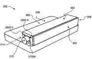
图2图示了圆筒形侧面发光模块的透视图。Fig. 2 illustrates a perspective view of a cylindrical side lighting module.
图3A图示了线形顶部发光模块的透视图。Fig. 3A illustrates a perspective view of a linear top lighting module.
图3B图示了线形侧面发光模块的透视图。Fig. 3B illustrates a perspective view of a linear side lighting module.
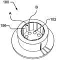
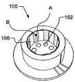
图4A、4B和4C以多种配置图示了图1中的圆筒形顶部发光模块的透视图,其中去除了顶部窗口。Figures 4A, 4B and 4C illustrate perspective views of the cylindrical top lighting module of Figure 1 in various configurations with the top window removed.
图5图示了图1中的圆筒形顶部发光模块的分解透视图。FIG. 5 illustrates an exploded perspective view of the cylindrical top lighting module in FIG. 1 .
图6图示了图2中的圆筒形侧面发光模块的分解透视图。FIG. 6 illustrates an exploded perspective view of the cylindrical side light emitting module in FIG. 2 .
图7图示了图3A中的线形顶部发光模块的分解透视图。Fig. 7 illustrates an exploded perspective view of the linear top lighting module in Fig. 3A.
图8图示了图3B中的线形侧面发光模块的分解透视图。Fig. 8 illustrates an exploded perspective view of the linear side light emitting module in Fig. 3B.
图9图示了用作搁板灯的线形侧面发光模块的例子。Fig. 9 illustrates an example of a linear side lighting module used as a shelf light.
图10图示了一种实施方式,其中马达用来旋转圆筒形模块的侧壁。Figure 10 illustrates an embodiment in which a motor is used to rotate the side wall of the cylindrical module.
具体实施方式Detailed ways
图1A示出了圆筒形模块100的一种实施方式。该模块具有位于顶部104的光输出窗口102、具有侧壁107的中间部分106、和可以包括安装板和散热装置109的底部部分108、以及模块内的腔110(参见图4A)。One embodiment of a
在该实施方式中,中间部分106可以相对于底部部分108如箭头101所示地旋转。这种旋转将改变由顶部部分104、中间部分106和底部部分108形成的腔110的光学特性,以便改变通过输出窗口102的光的光谱输出。这将在接下来的部分中更详细地说明。In this embodiment, the
中间部分106和底部部分108可以具有刻线、字母或任何其它指示112,其给发光模块的安装人员或用户与中间部分与顶部部分的相对取向相关的光输出的指示。如图1A所示,在底部部分108显示了三条线,在中间部分106上显示一条线。如果中间部分106上的线与底部部分108上的右侧线对齐,则模块100产生通过顶部窗口102的具有约2700K的相关色温(CCT)的白光。通过将中间部分106向左旋转,通过将中间部分106上的线与底部部分的中间或左侧线对齐,可以分别产生具有3000K或4000K的CCT的白光。The
图1B示意性地图示了接收电输入120和产生具有可变光谱的光输出130的颜色可调模块100。Figure IB schematically illustrates a
图2示出了圆筒形模块200的一个实施方式,其类似于图1中示出的模块具有指示线112,但该实施方式配置为通过侧壁202发光,并且顶部204由反射材料制成。在这种配置中,通过相对于底部部分208旋转顶部部分204和/或中间部分206(即具有光输出窗口的侧壁202),通过改变由顶部反射器、中间部分206的透明或半透明侧壁202以及可以包括安装板和散热装置的底部部分208形成的内部腔的光学特性,可以改变光输出的颜色。Fig. 2 shows an embodiment of a
图3A示出了线形模块300的实施方式。该模块具有位于顶部部分304的矩形光输出窗口302,并包括具有侧壁307的中间部分306以及可以包括安装板和散热装置309的底部部分308。在该实施方式中,模块300具有调节旋钮312,其可以旋转,以改变通过光输出窗口302发射的光的光谱特性。在这种情况中,旋钮312和中间部分306可以具有刻线、字母任何其它指示314,其给发光模块300的安装人员或用户指示与旋钮312相对于中间部分306限定的壳体的方位相关的光输出。FIG. 3A shows an embodiment of a
图3B示出具有侧面发光结构的线形模块350的实施方式,其中光输出窗口352设置在模块350的侧面部分356处。模块350具有位于侧面部分356一侧的矩形光输出窗口352和侧面部分356上的反射壁,该反射壁位于与窗口352相对的一侧360处并在顶部354和底部部分358靠近光输出窗口352,底部部分358可以包括安装板和散热装置。在该实施方式中,模块350也具有调节旋转312,其可以旋转以改变通过光输出窗口352发射的光的频谱特性。再一次,旋钮312和中间部分356可以具有刻线、字母任何其它指示314,其给发光模块的安装人员或用户指示与旋钮相对于壳体的方位相关的光输出。FIG. 3B shows an embodiment of a
图4A示出了来自图1的圆筒形模块100的透视图,其中去除了光输出窗口102以示出模块的内部腔110。光输出窗口102由透明或半透明板构成,并且可以包含波长转换元件,如磷光材料,其可以分散在窗口102的材料中,或者可以涂敷成面对内部腔的表面或面向外的表面上的涂层,或者可以涂敷为两个表面上的涂层。如果使用磷光材料,则采用具有高导热性的板是有利的,诸如包含或由氧化铝制成的板,单晶形式的氧化铝称为蓝宝石,多晶形式的氧化铝称为矾土。光输出窗口102在所发射的波长下具有低吸收性。Figure 4A shows a perspective view of the
如在图4A中可以看到的那样,圆筒形模块100包括多个发光器152、底部反射器154、多个侧面反射器156和中间部分106的内壁158。As can be seen in FIG. 4A , the
发光器152例如为发光二极管,如由Philips Lumileds Lighting(CA,USA)或Nichia Corporation(Japan)或Cree(NC,USA)制造的。特别地,如由Philips Lumileds Lighting制造的Luxeon Rebel是可以用在模块100中的发光二极管组件,但也可以使用其它发光半导体、诸如激光器之类的其它光源、或小型放电管。典型地,根据所要求的电输入和/或辐射度输出功率,使用4至12个发光器152。The
发光器152连接至电路板和散热器(这些附图中不可见)。安装板包括用于发光器152的电连接,并且具有用于降低从发光器152到散热器的热阻的热接触区域(优选在所述板的两侧)和通孔。可以使用蓝色或UV发光器152,或者也可以使用蓝色、UV、绿色、琥珀色或红色发光器152的组合。The
为了实现良好的发光效率(高光输出与电功率输入比),由光输出窗口102、侧面反射器156和内壁158以及底部部分108形成的腔110的所有内表面都可以具有低的光学吸收。为此目的,底部反射器154可以由涂敷具有高反射率的材料的电路板形成,或者可以在电路板之上安装高反射板。例如,在图4A中,高反射板示出为底部反射器154,其具有切割出的圆形区域,以提供至发光器152的透镜的光学入口。这种反射板的一个例子是由称为Miro的材料制成的板,其由称为Alanod的公司(Germany)制造。反射板可以较薄,优选小于0.5mm,但优选小于0.25mm。To achieve good luminous efficiency (high light output to electrical power input ratio), all inner surfaces of
如图4A所示,侧面反射器156连接至底部反射器154。底部反射器154和侧面反射器156例如可以由一块板切割而成,其中每个侧面反射器156向上弯曲,并通过使该结构向下进入腔110而安装在发光器152上方。底部反射器154和侧面反射器156可以直接或间接地连接至底部部分108(例如通过胶粘或螺纹连接),并且不与具有侧壁107的中间部分106一起旋转。底部反射器154和/或侧壁反射器156可以覆盖有高反射性漫射涂层,如包含二氧化钛、二氧化镁或氧化铝颗粒的涂层,或者可以包含诸如磷光材料之类的波长转换材料。
该实施方式中的中间部分106具有内部侧壁158,其具有低吸收性(如铝或银涂层),并且至少部分地覆盖有诸如磷光材料层的光谱转换层。The
在一种实施方式中,使用8个发光器152和8个侧面反射器156,使得腔110的内部侧壁被分成16个部分。16个侧壁部分中的8个涂敷有具有第一反射率(如,光谱反射系数、性质)的层(由侧壁部分A表示),16个侧壁部分中的其它8个具有第二反射率(如,光谱反射系数、性质)(由侧壁部分B表示)。具有不同反射特性的两组区域相互隔开。In one embodiment, 8
在一个方位上,侧壁部分A几乎完全地暴露给发光器152,而侧壁部分B被隐藏而避免露出,因为它们在侧面反射器156的后面,如图4B所示。在图4C中,该模块具有相反的方位,侧壁部分B完全暴露至发光器152的光输出,而侧壁部分A被侧面反射器156覆盖。In one orientation, sidewall portion A is almost completely exposed to
在一种实施方式中,选择底部反射器154和/或侧面反射器156的涂层、内侧壁158的涂层和光输出窗口102的涂层,使得如果侧壁部分A完全露出,则产生具有约4000K的相关色温的白光,而如果侧壁部分B完全露出,则获得具有约2700K的相关色温的白光。通过部分地露出侧壁部分A和侧壁部分B,则可以获得具有在2700K和4000K之间的相关色温的白光。In one embodiment, the coating of the
虽然在该实施方式中使用了8个发光器152,但也可以使用其它数量的发光器152和侧面反射器156。此外,具有不同反射特性的侧壁部分的数量可以多于2个部分,即多于图示的部分A和部分B。而且,虽然侧壁部分和侧面反射器图示为垂直的条,但也可以使用其它结构。Although eight
图5为图1中的圆筒形模块100的一种实施方式的分解图,其中的部件被单独地示出。图5中的顶部元件为光输出窗口102,其具有透光特性。在由发光器152产生的光入射到窗口102之前从腔中的其它元件反射时,由发光器152产生的光直接或间接地照亮窗口102。这种光的一部分由窗口102透射并从模块的顶部发射。在通过所述板传输期间,所述光被至少部分地重新分布,例如光通过由包含在窗口102内的或连接至窗口102的颗粒散射,或光通过使所述窗口的两个表面中的至少一个粗糙(这例如可以通过对这种表面进行喷砂而进行)散射。FIG. 5 is an exploded view of one embodiment of the
该图中可见的第二元件是分段式圆筒形环160,其具有内壁158和外壁162,其中内壁的表面至少部分地覆盖有光学涂层159,并且其中该光学涂层159改变由该涂层反射的光的光谱特性。这种光学涂层159可以包括染料、磷光材料(如黄色磷光材料YAG(Y3Al5O12:Ce)材料、或绿色磷光材料Ca3Sc2Si3O12:Ce,或另一种绿色磷光材料Ca3(Sc,Mg)2Si3O12:Ce,或另一种绿色磷光材料CaSc2O4:Ce,或红色磷光材料CaAlSiN3:Eu,或另一种红色磷光材料(Sr,Ca)AlSiN3:Eu),或可以为由不同材料的层构成de薄涂层,其中材料的厚度和类型确定光谱反射特性。在一种实施方式中,内表面158细分成总共16个子部分,其中所述子部分交替地具有或不具有这种涂层,或者具有包括光学涂层的不同成分的交替涂层。环160优选由高反射材料制成,并且优选由具有良好的导热性的材料制成,如铝基反射材料。这些类型的反射材料例如由Alanod(Germany)制造,并具有商品名Miro,但也可以使用由其它公司制造的类似的材料。环160例如可以通过将反射涂层涂敷在该反射器材料的平的条上,并且在涂层159已经固化之后弯曲反射器而制成。The second element visible in this figure is a segmented
该图中图示的第三个元件是侧壁107,其用作调节件并且是模块100的壳体的一部分,有涂层的圆筒形环160放入侧壁107中并连接至侧壁107,并且输出窗口102在顶部处连接至该侧壁107。侧壁107由具有良好的导热性的材料(如铜或铝)制成。侧壁107件可以具有用于标记调节件(具有连接的具有涂层的环160)相对于包括安装板或底部散热器的底部件108的相对方位的标记112或指示。此外,侧壁107调节件可以具有便于手动旋转调节件的表面结构,或者可以具有允许连接马达以通过远程控制旋转调节件的安装部件。The third element illustrated in this figure is the
示出的第四个元件是反射器结构166,其由底部反射器154和侧面反射器156构成,底部反射器154为具有压制孔的圆盘形式,所述压制孔用于围绕发光器152的光学输出孔装配该圆盘,侧面反射器156形成为连接至该圆盘的矩形反射器元件,其沿垂直于该圆盘的方向放置,并具有约与环160相同的高度。该反射器结构优选由高反射性材料制成,并且例如可以注射模制,或者可以由高反射金属板通过压制和弯曲形成。这种金属板材料为如Alanod(Germany)制造的Miro材料。The fourth element shown is a
最后一个元件是包括安装板168的底部结构108,发光器152和反射器结构166连接到安装板168上。安装板168例如由铝或铜盘构成,在盘的顶部连接印刷电路板。印刷电路板提供至发光器152的电连接,发光器152通过熟知的回流焊接技术焊接至电路板。电线焊接至电路板,使得发光器可以连接至电驱动器并由电驱动器操作。除了单独的电路板和金属盘或板之外,还可以使用所谓的金属(或铝)芯片印刷电路板,例如由SierraProto Express(Sunnyvale CA,USA)制造的。除了板,电路板还可以直接连接至散热器或风扇或其它冷却装置。底部结构108还可以具有用于指示调节件相对于安装板的旋转或指示光输出的相关颜色或色温的标记170、指示器或刻线。The last element is the
图6示出了图2的圆筒形侧面发射器模块200的分解图。模块200包括顶部反射器204,其可以为塑料件,在面向光源的一侧具有高漫射或镜面反射表面,或者由诸如由Alanod制造的Miro材料之类的高导热和光学反射材料制成。顶部反射器204还可以由金属件制成,并涂敷有高反射材料,例如包含由化学式TiO2、MgO2、ZnO、AlO2、BaSO4、Y3Al5O12:Ce3+、Sb2O3、Ca3Sc2Si3O12:Ce、Ca3(Sc,Mg)2Si3O12:Ce、CaSc2O4:Ce、CaAlSiN3:Eu、(Sr,Ca)AlSiN3:Eu表示的材料中的一种或多种。该列表中包含化学元素Ce或Eu的材料或称为磷光材料的发光材料的例子,其将蓝光或UV光转换成较长波长的光,具有青色、绿色、琥珀色或红色。典型地,这些材料添加至透明或半透明的诸如环氧树脂或硅树脂之类的粘合料,并作为涂层通过丝网印刷(screen printing)、刮片、带铸或喷漆或任何其它适合的涂层技术涂敷到表面上。层厚度可以改变,但通常在30至100微米的范围内。FIG. 6 shows an exploded view of the cylindrical
连接至顶部反射器204的为侧壁部分206,在该实施方式中其由具有低吸收性的材料制成,并且可以具有散射特性。侧壁206具有圆筒形或多边形剖面。在一种实施方式中,侧壁206由具有不同粉末的材料制成,如AlO2和诸如Y3A15O12:Ce3+之类的磷光材料的组合,并且采用模具将所述粉末压成圆柱形并在炉中烧结。在另一种实施方式中,侧壁206由玻璃或蓝宝石管制成,并在管的内部或外部涂敷有粉末。用粉末涂敷管是非常普通的制造光源的技术,如荧光管,并且在本申请中可以采用相同的技术。Attached to the
为了在这种结构中实现模块光输出的光谱组成的改变,侧壁206具有至少两组带形部分,标识为A和B。每一组具有至少一个构件(带形部分),其中带形部分的光谱透射特性(或'颜色')不同。侧壁206上的带形部分A和B可以通过两种材料的共挤压(co-extrusion)形成,其中这两种材料具有不同的光谱透射特性。一种材料可以包含产生具有约4000K的相关色温的光输出的磷光材料混合物,而另一种材料可以包含产生具有约2700K的相关色温的光输出的磷光材料混合物。除了磷光材料混合物之外,所述材料具有粘合料,如氧化铝粉末,并且可以包含其它材料,以便于共挤压加工。共挤压是公知的工艺:一个简单的例子是条纹饮料吸管的制造,其中例如红色塑性材料与白色塑性材料共挤压成型。如果使用粉末,则可以使用模压技术,其中在高压下注入并压缩粉末,并将其加热以熔合在一起。作为替换,侧壁206可以由不同材料的矩形件构建,其被粘合或机械安装,以形成多边形剖面形状。In order to achieve a change in the spectral composition of the module's light output in this configuration,
模块100包括位于侧壁206的带形部分A、B之间的一组反射器220和发光器252。在一种实施方式中,该组反射器220在模块200的底部部分208连接至安装板209。如果需要,反射器220可以可替换地安装至顶部反射器204,在这种情况中,顶部反射器204和侧壁部分206可旋转地连接。在图6中示出的实施方式中,侧壁206和顶部反射器204在侧壁206底部处的可选的环207的帮助下相对于底部部分208旋转。环207可以以足够由手或通过采用工具或马达使环207以及连接的侧壁206和顶部反射器204旋转的空间搭扣配合至安装板209。环207可以包括用于标记环相对于底部部分208上的标记170的相对方位的标记112或指示器。在一种操作模式中,侧壁206相对于反射器220定位为使得主要是带形部分A由发光器252照射,并且该模块产生具有相对低的相关色温(如2700K或3000K)的光。在另一种操作模式,所谓方位是使得仅带形部分B被照射,并且从该模块获得具有相对高的相关色温(如3500K或4000K)的光。反射器220优选由高反射材料(对可见光的具有低吸收的材料)制成,并可以包含散射光的磷光材料颗粒或其它颗粒。这些颗粒可以嵌入形成反射器220的材料中,如聚合物材料(如果反射器由塑性材料注射模制),或者可以嵌入用来涂敷反射器220(以使它具有高反射率)的材料中。如果使用磷光材料,则优选选择具有高导热性的材料,如铝或铜。作为对使用金属的替换,还可以将其它导热聚合物用作基础材料或基底材料,例如由位于Warwick(RI,USA)的Cool Polymers公司制造的。The
该实施方式中的模块200的底部部分208包含发光器252,其连接至安装板209,该安装板包含用于向发光器供给电流的导电迹线。安装板209可以由具有高导热性的材料制成,或者包含具有高导热性的热路径,如FR4印刷电路板中的铜通孔。安装板209优选连接至由具有高导热性的诸如铝或铜的材料制成的散热装置。散热装置可以由导热聚合物(例如由位于Warwick(RI,USA)的Cool Polymers公司制造的)制成。这些材料的例子是导热液晶聚合物(LCP)、聚亚苯基硫醚(PPS)和热塑性弹性体(TPE)。The
图7示出了图3A中示出的线形模块300的分解图。线形模块300类似于图1和4中示出的圆筒形模块100,但在几方面存在不同。线形模块300包括矩形形状的光输出窗口302,其可以具有5至15mm的宽度和25至75mm的长度,但也可以使用其它宽度和长度。此外,与圆筒形模块100不同,线形模块300不移动或旋转侧壁。线形模块100包括在由顶部部分304、侧面部分306和底部部分308形成的腔310中线性平移的一组反射器320。通过采用位于侧壁307中的螺纹孔322旋转螺钉312而平移反射器结构,使用调节螺钉312线性移动反射器320。侧壁307安装至安装板309。侧壁307涂敷有至少一个光学涂层区域,其在反射时改变光的颜色。优选地,具有两组涂敷区域A和B,每组区域具有至少与反射器结构320中的反射器的数量相同的区域数量。如果一个涂敷区域A暴露于来自发光器152的光,则模块300的光输出具有约2700K的相关色温,并且其中如果另一组区域B暴露于发光器152的光,则模块的光输出具有4000K的相关色温。除此范围之外,还可以调节模块,以发射更小或更大的相关色温范围。Fig. 7 shows an exploded view of the
图8示出了图3B中示出的线形侧面发射器模块350的分解图,其中光输出窗口352垂直于底部部分358的安装板359放置。图8中的线形侧面发射器模块350与图7中的线形模块300类似,类似的设计元件相同。然而,线形侧面发射器模块350具有垂直于安装板359定位的光输出窗口352。这种结构在诸如图9中图示的搁板照明之类的应用中是有利的,其中模块350的高度需要小。在线形侧面发射器模块350中,反射器370由L形反射镜构成,其覆盖与光输出窗口352相对的侧壁360和与发光器152相对的顶部壁354。涂敷区域A、B放置在该侧壁360和顶部壁354上。该结构的剩余部分类似于如图7所示并参照图7描述的实施方式起作用。FIG. 8 shows an exploded view of the linear
图9图示了用作搁板灯的线形侧面发射器模块350的例子。如果需要,可以使用图3A和7中的线形模块300。模块350本身在图9中不可见,因为它隐藏在反射器394的后面,并且集成在上搁板390中,以照射下搁板392。上搁板390可以用作散热装置和散热器。如图所示,三个模块350可以用来均匀地照射下搁板392。可替换地,模块350可以用作“撑墙支架板”式灯具,作为室外光照射墙壁,或用于形成人工效果。Figure 9 illustrates an example of a linear
图10图示了一种实施方式,其中马达400用来旋转图1中示出的圆筒形模块100的侧壁107。然而,应当理解,马达400可以与在此描述的任何实施方式一起使用。在该实施方式中,圆筒形发光模块100放置在安装板402上,靠近发光模块100的是安装在同一安装板402上的马达400。控制箱410与用于该模块中的发光器阵列的驱动器412和用于马达400的驱动器414包括在一起。控制箱410连接至电源(或直接连接至干线),如图电源线416所示,以及如图控制线418所示的控制接口。控制接口可以为DMX512接口,其为由标准"E1.11,USITT DMX512–A"(简称"DMX512-A")限定的照明控制接口,并且由ESTA(Entertainment Servicesand Technology Association)主张。齿轮420、422分别连接至马达400和侧壁107。当启动马达400时,侧壁107旋转,因此,模块100的光谱输出如上所述进行改变。该结构具有的优势在于,如果保持模块100的灯具不容易接近或是热的,则它仍然能够被容易地操作,以改变颜色。FIG. 10 illustrates an embodiment in which a
虽然联系用于教导目的的特定实施方式说明了本发明,但本发明不限于此。在不偏离本发明的范围的条件下可以进行多种改装和修改。因此,随附权利要求的精神和范围不应当限于前述描述。While the invention has been described in connection with particular embodiments for teaching purposes, the invention is not limited thereto. Various adaptations and modifications can be made without departing from the scope of the present invention. Therefore, the spirit and scope of the appended claims should not be limited to the foregoing description.
Claims (20)
Translated fromChineseApplications Claiming Priority (5)
| Application Number | Priority Date | Filing Date | Title |
|---|---|---|---|
| US8757008P | 2008-08-08 | 2008-08-08 | |
| US61/087,570 | 2008-08-08 | ||
| US12/538,003 | 2009-08-07 | ||
| US12/538,003US7942540B2 (en) | 2008-08-08 | 2009-08-07 | Color tunable light source |
| PCT/US2009/053221WO2010017523A1 (en) | 2008-08-08 | 2009-08-07 | Color tunable light source |
Publications (2)
| Publication Number | Publication Date |
|---|---|
| CN102112807A CN102112807A (en) | 2011-06-29 |
| CN102112807Btrue CN102112807B (en) | 2014-04-23 |
Family
ID=41652766
Family Applications (1)
| Application Number | Title | Priority Date | Filing Date |
|---|---|---|---|
| CN200980130229.4AExpired - Fee RelatedCN102112807B (en) | 2008-08-08 | 2009-08-07 | Color adjustable light source |
Country Status (10)
| Country | Link |
|---|---|
| US (2) | US7942540B2 (en) |
| EP (1) | EP2321576B1 (en) |
| JP (1) | JP5372155B2 (en) |
| KR (1) | KR20110044228A (en) |
| CN (1) | CN102112807B (en) |
| BR (1) | BRPI0911940A2 (en) |
| CA (1) | CA2730719A1 (en) |
| ES (1) | ES2397208T3 (en) |
| MX (1) | MX2011001055A (en) |
| WO (1) | WO2010017523A1 (en) |
Families Citing this family (86)
| Publication number | Priority date | Publication date | Assignee | Title |
|---|---|---|---|---|
| US8783887B2 (en) | 2007-10-01 | 2014-07-22 | Intematix Corporation | Color tunable light emitting device |
| CA2730719A1 (en)* | 2008-08-08 | 2010-02-11 | Xicato, Inc. | Color tunable light source |
| DE102008047085B4 (en)* | 2008-09-12 | 2016-02-18 | Gp Inspect Gmbh | lighting device |
| US8858032B2 (en)* | 2008-10-24 | 2014-10-14 | Cree, Inc. | Lighting device, heat transfer structure and heat transfer element |
| CN101994934B (en)* | 2009-08-14 | 2012-03-14 | 鸿富锦精密工业(深圳)有限公司 | Light-emitting device |
| JP5694369B2 (en)* | 2009-12-17 | 2015-04-01 | コーニンクレッカ フィリップス エヌ ヴェ | Cinema environmental lighting system |
| EP3133579B1 (en) | 2010-01-29 | 2020-03-04 | Avery Dennison Corporation | Smart sign box using electronic interactions |
| US10977965B2 (en) | 2010-01-29 | 2021-04-13 | Avery Dennison Retail Information Services, Llc | Smart sign box using electronic interactions |
| US9631782B2 (en)* | 2010-02-04 | 2017-04-25 | Xicato, Inc. | LED-based rectangular illumination device |
| US8668357B2 (en)* | 2010-03-15 | 2014-03-11 | Luxintec, S.L. | Luminaire with LED technology and method for obtaining said luminaire |
| DE102010030639B4 (en)* | 2010-06-29 | 2013-05-02 | Osram Gmbh | Lighting device with movable converter element |
| DE102010030938A1 (en)* | 2010-07-05 | 2012-01-05 | Osram Gesellschaft mit beschränkter Haftung | Light box and method for mixing light |
| US9101036B2 (en) | 2010-08-20 | 2015-08-04 | Research Triangle Institute | Photoluminescent nanofiber composites, methods for fabrication, and related lighting devices |
| US9562671B2 (en) | 2010-08-20 | 2017-02-07 | Research Triangle Institute | Color-tunable lighting devices and methods of use |
| WO2012024607A2 (en) | 2010-08-20 | 2012-02-23 | Research Triangle Institute, International | Lighting devices utilizing optical waveguides and remote light converters, and related methods |
| US8864326B2 (en)* | 2010-11-17 | 2014-10-21 | Light & Motion Industries | Adjustable light for underwater photography |
| US9746170B1 (en) | 2010-11-17 | 2017-08-29 | Light & Motion Industries | Adjustable light for underwater photography |
| TW201224364A (en)* | 2010-12-08 | 2012-06-16 | Foxsemicon Integrated Tech Inc | Light Emitting Diode tube |
| US8425065B2 (en)* | 2010-12-30 | 2013-04-23 | Xicato, Inc. | LED-based illumination modules with thin color converting layers |
| US20120201030A1 (en)* | 2011-02-07 | 2012-08-09 | Intematix Corporation | Photoluminescence color wheels |
| TW201243220A (en) | 2011-03-17 | 2012-11-01 | Rambus Inc | Lighting assembly with adjustable light output |
| TW201243239A (en) | 2011-03-17 | 2012-11-01 | Rambus Inc | Lighting assembly with adjustable light output |
| TW201241364A (en)* | 2011-03-17 | 2012-10-16 | Rambus Inc | Lighting assembly with adjustable light output |
| TW201248083A (en)* | 2011-03-17 | 2012-12-01 | Rambus Inc | Adjustable light source, and light bulb with adjustable light source |
| US8864360B2 (en)* | 2011-05-06 | 2014-10-21 | Rambus Delaware Llc | Lighting assembly |
| US9285107B2 (en) | 2011-06-10 | 2016-03-15 | Koninklijke Philips N.V. | Retrofit lighting device |
| WO2013000481A1 (en)* | 2011-06-29 | 2013-01-03 | Martin Professional A/S | Color mixing illumination device |
| WO2013008221A1 (en)* | 2011-07-08 | 2013-01-17 | Koninklijke Philips Electronics N.V. | Glowing luminaire housing with phosphor |
| WO2013007696A2 (en)* | 2011-07-11 | 2013-01-17 | Osram Ag | Lighting device having transparently covered semiconductor light sources |
| CN102392979A (en)* | 2011-07-28 | 2012-03-28 | 鸿富锦精密工业(深圳)有限公司 | Electronic equipment capable of regulating light-emitting rate |
| US8403529B2 (en) | 2011-08-02 | 2013-03-26 | Xicato, Inc. | LED-based illumination module with preferentially illuminated color converting surfaces |
| US8449129B2 (en) | 2011-08-02 | 2013-05-28 | Xicato, Inc. | LED-based illumination device with color converting surfaces |
| CN104025556B (en) | 2011-09-01 | 2018-08-10 | 艾利丹尼森公司 | Equipment, system and method for consumer's tracking |
| US9039217B2 (en) | 2011-09-21 | 2015-05-26 | Lg Innotek Co., Ltd. | Lighting device |
| JP5715307B2 (en)* | 2011-10-26 | 2015-05-07 | コーニンクレッカ フィリップス エヌ ヴェ | Light emitting device |
| US8630908B2 (en) | 2011-11-02 | 2014-01-14 | Avery Dennison Corporation | Distributed point of sale, electronic article surveillance, and product information system, apparatus and method |
| TWI435026B (en)* | 2011-11-07 | 2014-04-21 | 訊凱國際股份有限公司 | Illiminant device and lamp thereof and manufacturing method of the of the lamp |
| US20140140091A1 (en) | 2012-11-20 | 2014-05-22 | Sergiy Victorovich Vasylyev | Waveguide illumination system |
| CN103148361A (en)* | 2011-12-06 | 2013-06-12 | 欧司朗股份有限公司 | Illuminating device |
| KR20140107385A (en)* | 2011-12-19 | 2014-09-04 | 쓰리엠 이노베이티브 프로퍼티즈 캄파니 | Color shift sign |
| US9611982B2 (en)* | 2011-12-29 | 2017-04-04 | Pentair Water Pool And Spa, Inc. | LED replacement light assembly with improved cooling features |
| US10043952B2 (en) | 2012-03-30 | 2018-08-07 | Lumileds Llc | Light emitting device with wavelength converting side coat |
| US9383496B2 (en) | 2012-06-05 | 2016-07-05 | Rambus Delaware Llc | Edge lit lighting assembly with spectrum adjuster |
| EP2888526A2 (en)* | 2012-08-24 | 2015-07-01 | Koninklijke Philips N.V. | A lighting device |
| US9423105B2 (en) | 2012-08-24 | 2016-08-23 | Koninklijke Philips N.V. | Lighting device having electrically switchable optical member |
| US9734365B2 (en) | 2012-09-10 | 2017-08-15 | Avery Dennison Retail Information Services, Llc | Method for preventing unauthorized diversion of NFC tags |
| US9612002B2 (en) | 2012-10-18 | 2017-04-04 | GE Lighting Solutions, LLC | LED lamp with Nd-glass bulb |
| BR112014017152B8 (en) | 2012-10-18 | 2022-08-30 | Avery Dennison Corp | METHOD AND SYSTEM FOR NFC SECURITY |
| US9767329B2 (en) | 2012-11-19 | 2017-09-19 | Avery Dennison Retail Information Services, Llc | NFC tags with proximity detection |
| WO2014085670A1 (en) | 2012-11-30 | 2014-06-05 | Rambus Delaware Llc | Lighting assembly with defined angular output |
| FR2998945B1 (en)* | 2012-12-03 | 2014-11-21 | Lucibel Sa | ADJUSTABLE COLOR TEMPERATURE LIGHTING DEVICE |
| DE102013107722A1 (en)* | 2013-07-19 | 2015-01-22 | Osram Opto Semiconductors Gmbh | Optoelectronic semiconductor component and method for operating an optoelectronic semiconductor component |
| DE102013217319B4 (en)* | 2013-08-30 | 2024-11-07 | Osram Gmbh | lighting equipment |
| USD719109S1 (en)* | 2013-09-18 | 2014-12-09 | Lediamond Opto Corporation | LED structure |
| USD719110S1 (en)* | 2013-10-04 | 2014-12-09 | Lediamond Opto Corporation | LED structure |
| US9976710B2 (en)* | 2013-10-30 | 2018-05-22 | Lilibrand Llc | Flexible strip lighting apparatus and methods |
| US9427162B2 (en)* | 2013-11-11 | 2016-08-30 | Joshua Friedman | Dental shade matching method and device |
| USD742044S1 (en)* | 2013-11-15 | 2015-10-27 | Koito Manufacturing Co., Ltd. | Sidelight |
| USD743067S1 (en)* | 2013-11-15 | 2015-11-10 | Koito Manufacturing Co., Ltd. | Light fixture |
| US9816672B1 (en)* | 2013-11-18 | 2017-11-14 | Cooper Technologies Company | Configurable light source |
| DE102014009594A1 (en)* | 2014-06-27 | 2015-12-31 | Audi Ag | Lighting device for a motor vehicle with a safety device for detecting fault conditions and method for detecting fault conditions |
| JP6548152B2 (en)* | 2014-09-11 | 2019-07-24 | パナソニックIpマネジメント株式会社 | Lighting device |
| KR101601531B1 (en)* | 2014-11-07 | 2016-03-10 | 주식회사 지엘비젼 | Lighting Device |
| US10047940B2 (en) | 2015-04-25 | 2018-08-14 | Dawson I. Grunzweig | Removably connectable units for power, light, data, or other functions |
| DE102016200425B3 (en)* | 2016-01-15 | 2017-04-20 | Fraunhofer-Gesellschaft zur Förderung der angewandten Forschung e.V. | Flexible, environmentally friendly lamp device with gas discharge lamp and uses thereof |
| US11060702B2 (en) | 2016-03-08 | 2021-07-13 | Ecosense Lighting Inc. | Lighting system with lens assembly |
| EP3526518B1 (en) | 2016-11-10 | 2020-02-26 | Lumileds Holding B.V. | Led lighting unit |
| US12388056B1 (en) | 2017-01-27 | 2025-08-12 | Korrus, Inc. | Linear lighting systems and processes |
| WO2018140727A1 (en) | 2017-01-27 | 2018-08-02 | Lilibrand Llc | Lighting systems with high color rendering index and uniform planar illumination |
| US20180328552A1 (en) | 2017-03-09 | 2018-11-15 | Lilibrand Llc | Fixtures and lighting accessories for lighting devices |
| CN107131483A (en)* | 2017-07-05 | 2017-09-05 | 厦门多彩光电子科技有限公司 | Plant illumination system |
| CN108468975B (en)* | 2018-04-09 | 2020-07-14 | 湖南竞投智能信息技术有限公司 | Landscape brightening control device based on Internet of things technology |
| US11041609B2 (en) | 2018-05-01 | 2021-06-22 | Ecosense Lighting Inc. | Lighting systems and devices with central silicone module |
| US10448503B1 (en)* | 2018-05-07 | 2019-10-15 | Light & Motion Industries | Coplaner LED array and driver assembly |
| DE102019126521B4 (en)* | 2018-10-02 | 2025-05-08 | Electronic Theatre Controls, Inc. | Lighting fixtures |
| US11162663B2 (en) | 2018-10-02 | 2021-11-02 | Electronic Theatre Controls, Inc. | Lighting fixture |
| US11353200B2 (en) | 2018-12-17 | 2022-06-07 | Korrus, Inc. | Strip lighting system for direct input of high voltage driving power |
| KR20210123312A (en) | 2019-02-04 | 2021-10-13 | 덴카 주식회사 | reflector and irradiator |
| US10907799B1 (en)* | 2019-09-20 | 2021-02-02 | International Business Machines Corporation | Adjusting lumen output of a light assembly |
| CN111853656A (en)* | 2019-09-24 | 2020-10-30 | 扬州恒润光电科技有限公司 | Adjustable LED lamp |
| WO2022163175A1 (en)* | 2021-01-28 | 2022-08-04 | 日本特殊陶業株式会社 | Wavelength conversion member and light source device provided therewith |
| JP2022152505A (en)* | 2021-03-29 | 2022-10-12 | 岩崎電気株式会社 | Lighting fixture |
| DE102022112351B4 (en)* | 2021-09-14 | 2024-08-01 | Hsien-Sheng Lin | BEAM - UV - LED - ULTRAVIOLET LIGHT - SCANNING - METHOD AND DEVICE THEREFOR |
| CN215951294U (en)* | 2021-09-30 | 2022-03-04 | 中山博浪电子科技有限公司 | Reflected light projection device |
| KR20230051922A (en)* | 2021-10-12 | 2023-04-19 | 주식회사 쉘파스페이스 | Light device for light converting and film cartrige used in the same |
| JP7721481B2 (en)* | 2022-05-13 | 2025-08-12 | 日本特殊陶業株式会社 | Wavelength conversion member and light source device |
Citations (2)
| Publication number | Priority date | Publication date | Assignee | Title |
|---|---|---|---|---|
| US6357889B1 (en)* | 1999-12-01 | 2002-03-19 | General Electric Company | Color tunable light source |
| US20070236933A1 (en)* | 2006-04-06 | 2007-10-11 | Philips Lumileds Lighting Company Llc | Angular dependent element positioned for color tuning |
Family Cites Families (22)
| Publication number | Priority date | Publication date | Assignee | Title |
|---|---|---|---|---|
| US6600175B1 (en)* | 1996-03-26 | 2003-07-29 | Advanced Technology Materials, Inc. | Solid state white light emitter and display using same |
| KR100537349B1 (en)* | 1996-06-26 | 2006-02-28 | 오스람 게젤샤프트 미트 베쉬랭크터 하프퉁 | Light-emitting semiconductor component with luminescence conversion element |
| US5959316A (en)* | 1998-09-01 | 1999-09-28 | Hewlett-Packard Company | Multiple encapsulation of phosphor-LED devices |
| US6351069B1 (en)* | 1999-02-18 | 2002-02-26 | Lumileds Lighting, U.S., Llc | Red-deficiency-compensating phosphor LED |
| US6680569B2 (en)* | 1999-02-18 | 2004-01-20 | Lumileds Lighting U.S. Llc | Red-deficiency compensating phosphor light emitting device |
| TW455908B (en)* | 1999-04-20 | 2001-09-21 | Koninkl Philips Electronics Nv | Lighting system |
| US6504301B1 (en)* | 1999-09-03 | 2003-01-07 | Lumileds Lighting, U.S., Llc | Non-incandescent lightbulb package using light emitting diodes |
| CN100468791C (en)* | 2002-08-30 | 2009-03-11 | 吉尔科有限公司 | Light emitting diode with improved effience |
| US7250715B2 (en)* | 2004-02-23 | 2007-07-31 | Philips Lumileds Lighting Company, Llc | Wavelength converted semiconductor light emitting devices |
| JP2006059760A (en)* | 2004-08-23 | 2006-03-02 | Nec Lighting Ltd | Luminaire |
| US7564180B2 (en)* | 2005-01-10 | 2009-07-21 | Cree, Inc. | Light emission device and method utilizing multiple emitters and multiple phosphors |
| JP4354435B2 (en)* | 2005-07-13 | 2009-10-28 | 三菱電機株式会社 | Light emitting device and lighting device |
| US7543959B2 (en)* | 2005-10-11 | 2009-06-09 | Philips Lumiled Lighting Company, Llc | Illumination system with optical concentrator and wavelength converting element |
| CN101351891B (en)* | 2005-12-22 | 2014-11-19 | 科锐公司 | lighting device |
| WO2007102098A1 (en)* | 2006-03-06 | 2007-09-13 | Koninklijke Philips Electronics N.V. | Light-emitting diode module |
| ATE538400T1 (en)* | 2007-06-04 | 2012-01-15 | Koninkl Philips Electronics Nv | LIGHTING SYSTEM, LAMP AND CHANDELIER WITH COLOR ADJUSTMENT |
| US7942556B2 (en) | 2007-06-18 | 2011-05-17 | Xicato, Inc. | Solid state illumination device |
| JP2010534411A (en)* | 2007-07-25 | 2010-11-04 | コーニンクレッカ フィリップス エレクトロニクス エヌ ヴィ | Color conversion element and light output device capable of color control |
| DE102007037875A1 (en) | 2007-08-10 | 2009-02-12 | Osram Gesellschaft mit beschränkter Haftung | Radiation-emitting device |
| US7984999B2 (en) | 2007-10-17 | 2011-07-26 | Xicato, Inc. | Illumination device with light emitting diodes and moveable light adjustment member |
| DE102008031996A1 (en)* | 2008-07-07 | 2010-02-18 | Osram Gesellschaft mit beschränkter Haftung | Radiation-emitting device |
| CA2730719A1 (en)* | 2008-08-08 | 2010-02-11 | Xicato, Inc. | Color tunable light source |
- 2009
- 2009-08-07CACA2730719Apatent/CA2730719A1/ennot_activeAbandoned
- 2009-08-07WOPCT/US2009/053221patent/WO2010017523A1/enactiveApplication Filing
- 2009-08-07JPJP2011522297Apatent/JP5372155B2/ennot_activeExpired - Fee Related
- 2009-08-07KRKR1020117003561Apatent/KR20110044228A/ennot_activeWithdrawn
- 2009-08-07MXMX2011001055Apatent/MX2011001055A/enactiveIP Right Grant
- 2009-08-07CNCN200980130229.4Apatent/CN102112807B/ennot_activeExpired - Fee Related
- 2009-08-07EPEP09791320Apatent/EP2321576B1/ennot_activeNot-in-force
- 2009-08-07USUS12/538,003patent/US7942540B2/enactiveActive - Reinstated
- 2009-08-07ESES09791320Tpatent/ES2397208T3/enactiveActive
- 2009-08-07BRBRPI0911940Apatent/BRPI0911940A2/ennot_activeIP Right Cessation
- 2011
- 2011-05-10USUS13/104,285patent/US8297766B2/enactiveActive
Patent Citations (2)
| Publication number | Priority date | Publication date | Assignee | Title |
|---|---|---|---|---|
| US6357889B1 (en)* | 1999-12-01 | 2002-03-19 | General Electric Company | Color tunable light source |
| US20070236933A1 (en)* | 2006-04-06 | 2007-10-11 | Philips Lumileds Lighting Company Llc | Angular dependent element positioned for color tuning |
Also Published As
| Publication number | Publication date |
|---|---|
| JP2011530789A (en) | 2011-12-22 |
| KR20110044228A (en) | 2011-04-28 |
| EP2321576B1 (en) | 2012-10-10 |
| EP2321576A1 (en) | 2011-05-18 |
| US20100033948A1 (en) | 2010-02-11 |
| US7942540B2 (en) | 2011-05-17 |
| CA2730719A1 (en) | 2010-02-11 |
| US8297766B2 (en) | 2012-10-30 |
| WO2010017523A1 (en) | 2010-02-11 |
| ES2397208T3 (en) | 2013-03-05 |
| CN102112807A (en) | 2011-06-29 |
| MX2011001055A (en) | 2011-03-24 |
| US20110211344A1 (en) | 2011-09-01 |
| JP5372155B2 (en) | 2013-12-18 |
| BRPI0911940A2 (en) | 2015-10-13 |
Similar Documents
| Publication | Publication Date | Title |
|---|---|---|
| CN102112807B (en) | Color adjustable light source | |
| TWI532947B (en) | Light emitting device and method of manufacturing same | |
| US8967821B2 (en) | Lighting device with low glare and high light level uniformity | |
| CN102844619B (en) | There is the luminaire of radiating piece | |
| TWI539116B (en) | Led-based illumination module with preferentially illuminated color converting surfaces | |
| US8896005B2 (en) | Lighting devices that comprise one or more solid state light emitters | |
| TWI428542B (en) | Lighting unit having lighting strips with light emitting elements and a remote luminescent material | |
| TWI490435B (en) | Light emitting diode module with three part color matching | |
| CN102869914B (en) | High-efficiency LED-based lighting modules with high color rendering index | |
| US8028537B2 (en) | Heat sinking and flexible circuit board, for solid state light fixture utilizing an optical cavity | |
| RU2523052C2 (en) | Led-based lamps and systems for controlling heat therefrom | |
| TW201235617A (en) | Lighting device with multi-chip light emitters, solid state light emitter support members and lighting elements | |
| CN103765092A (en) | Direct view and rear view LED lighting system | |
| TW201020470A (en) | Lighting device | |
| CN103874876A (en) | Lighting device | |
| US9506622B2 (en) | Illumination device with carrier and envelope | |
| CN105190162A (en) | Modular Lens Troffer Luminaires | |
| US10962700B1 (en) | Field-reconfigurable luminaire | |
| HK1132787A1 (en) | Lamp |
Legal Events
| Date | Code | Title | Description |
|---|---|---|---|
| C06 | Publication | ||
| PB01 | Publication | ||
| C10 | Entry into substantive examination | ||
| SE01 | Entry into force of request for substantive examination | ||
| C14 | Grant of patent or utility model | ||
| GR01 | Patent grant | ||
| CF01 | Termination of patent right due to non-payment of annual fee | Granted publication date:20140423 Termination date:20150807 | |
| EXPY | Termination of patent right or utility model |