CN102112064A - Anchor delivery system with replaceable cartridge - Google Patents
Anchor delivery system with replaceable cartridgeDownload PDFInfo
- Publication number
- CN102112064A CN102112064ACN2009801300763ACN200980130076ACN102112064ACN 102112064 ACN102112064 ACN 102112064ACN 2009801300763 ACN2009801300763 ACN 2009801300763ACN 200980130076 ACN200980130076 ACN 200980130076ACN 102112064 ACN102112064 ACN 102112064A
- Authority
- CN
- China
- Prior art keywords
- assembly
- anchoring
- actuator
- conveyer device
- cartridge type
- Prior art date
- Legal status (The legal status is an assumption and is not a legal conclusion. Google has not performed a legal analysis and makes no representation as to the accuracy of the status listed.)
- Granted
Links
- 238000004873anchoringMethods0.000claimsdescription218
- 238000011282treatmentMethods0.000claimsdescription44
- 238000000034methodMethods0.000claimsdescription37
- 238000005520cutting processMethods0.000claimsdescription25
- 230000007246mechanismEffects0.000claimsdescription13
- 230000000712assemblyEffects0.000claimsdescription8
- 238000000429assemblyMethods0.000claimsdescription8
- 230000008569processEffects0.000claimsdescription5
- 230000009885systemic effectEffects0.000claims3
- 235000019589hardnessNutrition0.000claims1
- 230000035515penetrationEffects0.000claims1
- 210000001519tissueAnatomy0.000description39
- 210000003484anatomyAnatomy0.000description25
- 210000003708urethraAnatomy0.000description23
- 230000009471actionEffects0.000description21
- 210000002307prostateAnatomy0.000description20
- 208000004403Prostatic HyperplasiaDiseases0.000description19
- 206010004446Benign prostatic hyperplasiaDiseases0.000description18
- 210000003932urinary bladderAnatomy0.000description18
- 230000006698inductionEffects0.000description14
- 238000002513implantationMethods0.000description13
- 206010046543Urinary incontinenceDiseases0.000description12
- 239000000463materialSubstances0.000description12
- 210000002700urineAnatomy0.000description12
- 239000003814drugSubstances0.000description8
- 210000003205muscleAnatomy0.000description8
- 239000004744fabricSubstances0.000description7
- 239000007943implantSubstances0.000description7
- 238000005452bendingMethods0.000description6
- 239000002775capsuleSubstances0.000description6
- 238000000576coating methodMethods0.000description6
- 201000010099diseaseDiseases0.000description6
- 208000037265diseases, disorders, signs and symptomsDiseases0.000description6
- 230000000694effectsEffects0.000description6
- 210000000056organAnatomy0.000description6
- 210000003689pubic boneAnatomy0.000description6
- 239000000126substanceSubstances0.000description6
- 208000024891symptomDiseases0.000description6
- 230000008859changeEffects0.000description5
- 239000011248coating agentSubstances0.000description5
- 206010028980NeoplasmDiseases0.000description4
- 230000015572biosynthetic processEffects0.000description4
- 230000008878couplingEffects0.000description4
- 238000010168coupling processMethods0.000description4
- 238000005859coupling reactionMethods0.000description4
- 238000007789sealingMethods0.000description4
- 241001465754MetazoaSpecies0.000description3
- 238000013459approachMethods0.000description3
- 230000003796beautyEffects0.000description3
- 210000000988bone and boneAnatomy0.000description3
- 230000000295complement effectEffects0.000description3
- 230000006835compressionEffects0.000description3
- 238000007906compressionMethods0.000description3
- 229940079593drugDrugs0.000description3
- 230000007613environmental effectEffects0.000description3
- 210000003195fasciaAnatomy0.000description3
- 230000006870functionEffects0.000description3
- 230000036541healthEffects0.000description3
- 230000008520organizationEffects0.000description3
- 231100000915pathological changeToxicity0.000description3
- 230000036285pathological changeEffects0.000description3
- 230000002980postoperative effectEffects0.000description3
- 201000001514prostate carcinomaDiseases0.000description3
- 230000002441reversible effectEffects0.000description3
- 238000009958sewingMethods0.000description3
- 210000002784stomachAnatomy0.000description3
- 238000001356surgical procedureMethods0.000description3
- 239000000725suspensionSubstances0.000description3
- 238000002604ultrasonographyMethods0.000description3
- 210000001215vaginaAnatomy0.000description3
- KWGRBVOPPLSCSI-WPRPVWTQSA-N(-)-ephedrineChemical compoundCN[C@@H](C)[C@H](O)C1=CC=CC=C1KWGRBVOPPLSCSI-WPRPVWTQSA-N0.000description2
- 208000006735PeriostitisDiseases0.000description2
- MUMGGOZAMZWBJJ-DYKIIFRCSA-NTestostosteroneChemical compoundO=C1CC[C@]2(C)[C@H]3CC[C@](C)([C@H](CC4)O)[C@@H]4[C@@H]3CCC2=C1MUMGGOZAMZWBJJ-DYKIIFRCSA-N0.000description2
- 241000237983TrochidaeSpecies0.000description2
- 230000008901benefitEffects0.000description2
- 210000004204blood vesselAnatomy0.000description2
- 201000011510cancerDiseases0.000description2
- 238000010276constructionMethods0.000description2
- KWGRBVOPPLSCSI-UHFFFAOYSA-Nd-ephedrineNatural productsCNC(C)C(O)C1=CC=CC=C1KWGRBVOPPLSCSI-UHFFFAOYSA-N0.000description2
- 230000006378damageEffects0.000description2
- 238000003745diagnosisMethods0.000description2
- 238000007599dischargingMethods0.000description2
- 238000002651drug therapyMethods0.000description2
- 210000004709eyebrowAnatomy0.000description2
- 238000002695general anesthesiaMethods0.000description2
- 230000012010growthEffects0.000description2
- 238000003384imaging methodMethods0.000description2
- 238000009434installationMethods0.000description2
- 230000014759maintenance of locationEffects0.000description2
- 239000011159matrix materialSubstances0.000description2
- 230000027939micturitionEffects0.000description2
- 238000012986modificationMethods0.000description2
- 230000004048modificationEffects0.000description2
- 230000001575pathological effectEffects0.000description2
- 210000003460periosteumAnatomy0.000description2
- 229920000642polymerPolymers0.000description2
- 238000002360preparation methodMethods0.000description2
- 238000003825pressingMethods0.000description2
- 230000000750progressive effectEffects0.000description2
- 238000011160researchMethods0.000description2
- 238000012827research and developmentMethods0.000description2
- 238000007665saggingMethods0.000description2
- NVKAWKQGWWIWPM-ABEVXSGRSA-N17-β-hydroxy-5-α-Androstan-3-oneChemical compoundC1C(=O)CC[C@]2(C)[C@H]3CC[C@](C)([C@H](CC4)O)[C@@H]4[C@@H]3CC[C@H]21NVKAWKQGWWIWPM-ABEVXSGRSA-N0.000description1
- 102000019269Alpha 1A adrenoceptorHuman genes0.000description1
- 108050006749Alpha 1A adrenoceptorProteins0.000description1
- 235000018185Betula X alpestrisNutrition0.000description1
- 235000018212Betula X uliginosaNutrition0.000description1
- 108030001720BontoxilysinProteins0.000description1
- 108010066551Cholestenone 5 alpha-ReductaseProteins0.000description1
- 206010010356Congenital anomalyDiseases0.000description1
- 206010011732CystDiseases0.000description1
- 241000196324EmbryophytaSpecies0.000description1
- 206010019909HerniaDiseases0.000description1
- 206010020880HypertrophyDiseases0.000description1
- 206010021639IncontinenceDiseases0.000description1
- 241000404317LindaconusSpecies0.000description1
- 206010071289Lower urinary tract symptomsDiseases0.000description1
- 239000004642PolyimideSubstances0.000description1
- 206010051077Post procedural haemorrhageDiseases0.000description1
- 208000037486Postoperative HemorrhageDiseases0.000description1
- 206010036940Prostatic adenomaDiseases0.000description1
- 208000001647Renal InsufficiencyDiseases0.000description1
- FOIXSVOLVBLSDH-UHFFFAOYSA-NSilver ionChemical compound[Ag+]FOIXSVOLVBLSDH-UHFFFAOYSA-N0.000description1
- GUGOEEXESWIERI-UHFFFAOYSA-NTerfenadineChemical compoundC1=CC(C(C)(C)C)=CC=C1C(O)CCCN1CCC(C(O)(C=2C=CC=CC=2)C=2C=CC=CC=2)CC1GUGOEEXESWIERI-UHFFFAOYSA-N0.000description1
- 241001122767TheaceaeSpecies0.000description1
- 208000006568Urinary Bladder CalculiDiseases0.000description1
- 206010046996Varicose veinDiseases0.000description1
- 210000001015abdomenAnatomy0.000description1
- 230000003187abdominal effectEffects0.000description1
- 230000002159abnormal effectEffects0.000description1
- 230000003213activating effectEffects0.000description1
- 210000000577adipose tissueAnatomy0.000description1
- 230000003321amplificationEffects0.000description1
- 230000000202analgesic effectEffects0.000description1
- 238000004458analytical methodMethods0.000description1
- 229960003473androstanoloneDrugs0.000description1
- 238000010171animal modelMethods0.000description1
- 230000001387anti-histamineEffects0.000description1
- 239000000739antihistaminic agentSubstances0.000description1
- 239000012237artificial materialSubstances0.000description1
- 238000013542behavioral therapyMethods0.000description1
- 230000003115biocidal effectEffects0.000description1
- 239000008280bloodSubstances0.000description1
- 210000004369bloodAnatomy0.000description1
- 230000023555blood coagulationEffects0.000description1
- 210000001124body fluidAnatomy0.000description1
- 239000010839body fluidSubstances0.000description1
- 229940053031botulinum toxinDrugs0.000description1
- 210000000481breastAnatomy0.000description1
- 230000002308calcificationEffects0.000description1
- 239000003153chemical reaction reagentSubstances0.000description1
- SOYKEARSMXGVTM-UHFFFAOYSA-NchlorphenamineChemical compoundC=1C=CC=NC=1C(CCN(C)C)C1=CC=C(Cl)C=C1SOYKEARSMXGVTM-UHFFFAOYSA-N0.000description1
- 229960003291chlorphenamineDrugs0.000description1
- 230000001684chronic effectEffects0.000description1
- 238000010924continuous productionMethods0.000description1
- 239000011258core-shell materialSubstances0.000description1
- 239000002537cosmeticSubstances0.000description1
- 208000031513cystDiseases0.000description1
- 238000012217deletionMethods0.000description1
- 230000037430deletionEffects0.000description1
- 230000000994depressogenic effectEffects0.000description1
- 238000013461designMethods0.000description1
- 238000001514detection methodMethods0.000description1
- 238000011026diafiltrationMethods0.000description1
- ZZVUWRFHKOJYTH-UHFFFAOYSA-NdiphenhydramineChemical compoundC=1C=CC=CC=1C(OCCN(C)C)C1=CC=CC=C1ZZVUWRFHKOJYTH-UHFFFAOYSA-N0.000description1
- 229960000520diphenhydramineDrugs0.000description1
- 230000008034disappearanceEffects0.000description1
- DLNKOYKMWOXYQA-UHFFFAOYSA-Ndl-pseudophenylpropanolamineNatural productsCC(N)C(O)C1=CC=CC=C1DLNKOYKMWOXYQA-UHFFFAOYSA-N0.000description1
- 230000005611electricityEffects0.000description1
- 238000005516engineering processMethods0.000description1
- 229960002179ephedrineDrugs0.000description1
- 210000003238esophagusAnatomy0.000description1
- 210000000887faceAnatomy0.000description1
- 239000012530fluidSubstances0.000description1
- 230000001408fungistatic effectEffects0.000description1
- 230000035876healingEffects0.000description1
- 210000002216heartAnatomy0.000description1
- 210000002837heart atriumAnatomy0.000description1
- 208000006750hematuriaDiseases0.000description1
- 208000015181infectious diseaseDiseases0.000description1
- 239000004615ingredientSubstances0.000description1
- 230000003993interactionEffects0.000description1
- 230000007794irritationEffects0.000description1
- 201000006370kidney failureDiseases0.000description1
- 238000002430laser surgeryMethods0.000description1
- 210000003041ligamentAnatomy0.000description1
- 238000002690local anesthesiaMethods0.000description1
- 210000001365lymphatic vesselAnatomy0.000description1
- 230000036244malformationEffects0.000description1
- 238000004519manufacturing processMethods0.000description1
- 230000013011matingEffects0.000description1
- 238000012544monitoring processMethods0.000description1
- 230000009826neoplastic cell growthEffects0.000description1
- 210000005036nerveAnatomy0.000description1
- HLXZNVUGXRDIFK-UHFFFAOYSA-Nnickel titaniumChemical compound[Ti].[Ti].[Ti].[Ti].[Ti].[Ti].[Ti].[Ti].[Ti].[Ti].[Ti].[Ni].[Ni].[Ni].[Ni].[Ni].[Ni].[Ni].[Ni].[Ni].[Ni].[Ni].[Ni].[Ni].[Ni]HLXZNVUGXRDIFK-UHFFFAOYSA-N0.000description1
- 229910001000nickel titaniumInorganic materials0.000description1
- 238000003199nucleic acid amplification methodMethods0.000description1
- 210000003101oviductAnatomy0.000description1
- 230000001936parietal effectEffects0.000description1
- 230000007170pathologyEffects0.000description1
- 210000004197pelvisAnatomy0.000description1
- 230000008447perceptionEffects0.000description1
- 230000000737periodic effectEffects0.000description1
- 230000002093peripheral effectEffects0.000description1
- DLNKOYKMWOXYQA-APPZFPTMSA-NphenylpropanolamineChemical compoundC[C@@H](N)[C@H](O)C1=CC=CC=C1DLNKOYKMWOXYQA-APPZFPTMSA-N0.000description1
- 229960000395phenylpropanolamineDrugs0.000description1
- 238000009160phytotherapyMethods0.000description1
- 229920000052poly(p-xylylene)Polymers0.000description1
- 229920001721polyimidePolymers0.000description1
- 239000004810polytetrafluoroethyleneSubstances0.000description1
- 229920001343polytetrafluoroethylenePolymers0.000description1
- 239000000955prescription drugSubstances0.000description1
- 230000002265preventionEffects0.000description1
- 238000012545processingMethods0.000description1
- 238000011471prostatectomyMethods0.000description1
- 201000007094prostatitisDiseases0.000description1
- KWGRBVOPPLSCSI-WCBMZHEXSA-NpseudoephedrineChemical compoundCN[C@@H](C)[C@@H](O)C1=CC=CC=C1KWGRBVOPPLSCSI-WCBMZHEXSA-N0.000description1
- 229960003908pseudoephedrineDrugs0.000description1
- 102000005962receptorsHuman genes0.000description1
- 108020003175receptorsProteins0.000description1
- 238000002278reconstructive surgeryMethods0.000description1
- 210000000664rectumAnatomy0.000description1
- 238000002271resectionMethods0.000description1
- 239000000050smooth muscle relaxantSubstances0.000description1
- 238000002693spinal anesthesiaMethods0.000description1
- 229910001220stainless steelInorganic materials0.000description1
- 210000002435tendonAnatomy0.000description1
- 229960003604testosteroneDrugs0.000description1
- 229940124597therapeutic agentDrugs0.000description1
- 210000003437tracheaAnatomy0.000description1
- 230000017105transpositionEffects0.000description1
- 210000001113umbilicusAnatomy0.000description1
- 208000019206urinary tract infectionDiseases0.000description1
- 210000004291uterusAnatomy0.000description1
- 208000027185varicose diseaseDiseases0.000description1
- 230000000007visual effectEffects0.000description1
- 238000012800visualizationMethods0.000description1
- 238000004804windingMethods0.000description1
- 230000037303wrinklesEffects0.000description1
Images


Classifications
- A—HUMAN NECESSITIES
- A61—MEDICAL OR VETERINARY SCIENCE; HYGIENE
- A61B—DIAGNOSIS; SURGERY; IDENTIFICATION
- A61B17/00—Surgical instruments, devices or methods
- A61B17/04—Surgical instruments, devices or methods for suturing wounds; Holders or packages for needles or suture materials
- A61B17/0401—Suture anchors, buttons or pledgets, i.e. means for attaching sutures to bone, cartilage or soft tissue; Instruments for applying or removing suture anchors
- A—HUMAN NECESSITIES
- A61—MEDICAL OR VETERINARY SCIENCE; HYGIENE
- A61B—DIAGNOSIS; SURGERY; IDENTIFICATION
- A61B17/00—Surgical instruments, devices or methods
- A61B17/04—Surgical instruments, devices or methods for suturing wounds; Holders or packages for needles or suture materials
- A61B17/0469—Suturing instruments for use in minimally invasive surgery, e.g. endoscopic surgery
- A—HUMAN NECESSITIES
- A61—MEDICAL OR VETERINARY SCIENCE; HYGIENE
- A61B—DIAGNOSIS; SURGERY; IDENTIFICATION
- A61B17/00—Surgical instruments, devices or methods
- A61B17/00234—Surgical instruments, devices or methods for minimally invasive surgery
- A—HUMAN NECESSITIES
- A61—MEDICAL OR VETERINARY SCIENCE; HYGIENE
- A61B—DIAGNOSIS; SURGERY; IDENTIFICATION
- A61B17/00—Surgical instruments, devices or methods
- A61B17/32—Surgical cutting instruments
- A—HUMAN NECESSITIES
- A61—MEDICAL OR VETERINARY SCIENCE; HYGIENE
- A61B—DIAGNOSIS; SURGERY; IDENTIFICATION
- A61B17/00—Surgical instruments, devices or methods
- A61B17/34—Trocars; Puncturing needles
- A61B17/3468—Trocars; Puncturing needles for implanting or removing devices, e.g. prostheses, implants, seeds, wires
- A—HUMAN NECESSITIES
- A61—MEDICAL OR VETERINARY SCIENCE; HYGIENE
- A61B—DIAGNOSIS; SURGERY; IDENTIFICATION
- A61B17/00—Surgical instruments, devices or methods
- A61B17/34—Trocars; Puncturing needles
- A61B17/3478—Endoscopic needles, e.g. for infusion
- A—HUMAN NECESSITIES
- A61—MEDICAL OR VETERINARY SCIENCE; HYGIENE
- A61B—DIAGNOSIS; SURGERY; IDENTIFICATION
- A61B17/00—Surgical instruments, devices or methods
- A61B17/42—Gynaecological or obstetrical instruments or methods
- A—HUMAN NECESSITIES
- A61—MEDICAL OR VETERINARY SCIENCE; HYGIENE
- A61B—DIAGNOSIS; SURGERY; IDENTIFICATION
- A61B17/00—Surgical instruments, devices or methods
- A61B2017/00017—Electrical control of surgical instruments
- A61B2017/00022—Sensing or detecting at the treatment site
- A—HUMAN NECESSITIES
- A61—MEDICAL OR VETERINARY SCIENCE; HYGIENE
- A61B—DIAGNOSIS; SURGERY; IDENTIFICATION
- A61B17/00—Surgical instruments, devices or methods
- A61B17/00234—Surgical instruments, devices or methods for minimally invasive surgery
- A61B2017/00238—Type of minimally invasive operation
- A61B2017/00274—Prostate operation, e.g. prostatectomy, turp, bhp treatment
- A—HUMAN NECESSITIES
- A61—MEDICAL OR VETERINARY SCIENCE; HYGIENE
- A61B—DIAGNOSIS; SURGERY; IDENTIFICATION
- A61B17/00—Surgical instruments, devices or methods
- A61B2017/0046—Surgical instruments, devices or methods with a releasable handle; with handle and operating part separable
- A—HUMAN NECESSITIES
- A61—MEDICAL OR VETERINARY SCIENCE; HYGIENE
- A61B—DIAGNOSIS; SURGERY; IDENTIFICATION
- A61B17/00—Surgical instruments, devices or methods
- A61B2017/00743—Type of operation; Specification of treatment sites
- A61B2017/00792—Plastic surgery
- A—HUMAN NECESSITIES
- A61—MEDICAL OR VETERINARY SCIENCE; HYGIENE
- A61B—DIAGNOSIS; SURGERY; IDENTIFICATION
- A61B17/00—Surgical instruments, devices or methods
- A61B2017/00743—Type of operation; Specification of treatment sites
- A61B2017/00796—Breast surgery
- A—HUMAN NECESSITIES
- A61—MEDICAL OR VETERINARY SCIENCE; HYGIENE
- A61B—DIAGNOSIS; SURGERY; IDENTIFICATION
- A61B17/00—Surgical instruments, devices or methods
- A61B2017/00743—Type of operation; Specification of treatment sites
- A61B2017/00805—Treatment of female stress urinary incontinence
- A—HUMAN NECESSITIES
- A61—MEDICAL OR VETERINARY SCIENCE; HYGIENE
- A61B—DIAGNOSIS; SURGERY; IDENTIFICATION
- A61B17/00—Surgical instruments, devices or methods
- A61B17/04—Surgical instruments, devices or methods for suturing wounds; Holders or packages for needles or suture materials
- A61B17/0401—Suture anchors, buttons or pledgets, i.e. means for attaching sutures to bone, cartilage or soft tissue; Instruments for applying or removing suture anchors
- A61B2017/0409—Instruments for applying suture anchors
- A—HUMAN NECESSITIES
- A61—MEDICAL OR VETERINARY SCIENCE; HYGIENE
- A61B—DIAGNOSIS; SURGERY; IDENTIFICATION
- A61B17/00—Surgical instruments, devices or methods
- A61B17/04—Surgical instruments, devices or methods for suturing wounds; Holders or packages for needles or suture materials
- A61B17/0401—Suture anchors, buttons or pledgets, i.e. means for attaching sutures to bone, cartilage or soft tissue; Instruments for applying or removing suture anchors
- A61B2017/0417—T-fasteners
- A—HUMAN NECESSITIES
- A61—MEDICAL OR VETERINARY SCIENCE; HYGIENE
- A61B—DIAGNOSIS; SURGERY; IDENTIFICATION
- A61B17/00—Surgical instruments, devices or methods
- A61B17/04—Surgical instruments, devices or methods for suturing wounds; Holders or packages for needles or suture materials
- A61B17/0401—Suture anchors, buttons or pledgets, i.e. means for attaching sutures to bone, cartilage or soft tissue; Instruments for applying or removing suture anchors
- A61B2017/0419—H-fasteners
- A—HUMAN NECESSITIES
- A61—MEDICAL OR VETERINARY SCIENCE; HYGIENE
- A61B—DIAGNOSIS; SURGERY; IDENTIFICATION
- A61B17/00—Surgical instruments, devices or methods
- A61B17/04—Surgical instruments, devices or methods for suturing wounds; Holders or packages for needles or suture materials
- A61B17/0401—Suture anchors, buttons or pledgets, i.e. means for attaching sutures to bone, cartilage or soft tissue; Instruments for applying or removing suture anchors
- A61B2017/0464—Suture anchors, buttons or pledgets, i.e. means for attaching sutures to bone, cartilage or soft tissue; Instruments for applying or removing suture anchors for soft tissue
- A—HUMAN NECESSITIES
- A61—MEDICAL OR VETERINARY SCIENCE; HYGIENE
- A61B—DIAGNOSIS; SURGERY; IDENTIFICATION
- A61B17/00—Surgical instruments, devices or methods
- A61B17/04—Surgical instruments, devices or methods for suturing wounds; Holders or packages for needles or suture materials
- A61B17/0469—Suturing instruments for use in minimally invasive surgery, e.g. endoscopic surgery
- A61B2017/0479—Packages or dispensers for MIS suturing instruments
- A—HUMAN NECESSITIES
- A61—MEDICAL OR VETERINARY SCIENCE; HYGIENE
- A61B—DIAGNOSIS; SURGERY; IDENTIFICATION
- A61B17/00—Surgical instruments, devices or methods
- A61B17/04—Surgical instruments, devices or methods for suturing wounds; Holders or packages for needles or suture materials
- A61B17/0487—Suture clamps, clips or locks, e.g. for replacing suture knots; Instruments for applying or removing suture clamps, clips or locks
- A61B2017/0488—Instruments for applying suture clamps, clips or locks
- A—HUMAN NECESSITIES
- A61—MEDICAL OR VETERINARY SCIENCE; HYGIENE
- A61B—DIAGNOSIS; SURGERY; IDENTIFICATION
- A61B17/00—Surgical instruments, devices or methods
- A61B17/04—Surgical instruments, devices or methods for suturing wounds; Holders or packages for needles or suture materials
- A61B17/06—Needles ; Sutures; Needle-suture combinations; Holders or packages for needles or suture materials
- A61B2017/06052—Needle-suture combinations in which a suture is extending inside a hollow tubular needle, e.g. over the entire length of the needle
- A—HUMAN NECESSITIES
- A61—MEDICAL OR VETERINARY SCIENCE; HYGIENE
- A61B—DIAGNOSIS; SURGERY; IDENTIFICATION
- A61B17/00—Surgical instruments, devices or methods
- A61B17/04—Surgical instruments, devices or methods for suturing wounds; Holders or packages for needles or suture materials
- A61B17/06—Needles ; Sutures; Needle-suture combinations; Holders or packages for needles or suture materials
- A61B17/06066—Needles, e.g. needle tip configurations
- A61B2017/06095—Needles, e.g. needle tip configurations pliable
- A—HUMAN NECESSITIES
- A61—MEDICAL OR VETERINARY SCIENCE; HYGIENE
- A61B—DIAGNOSIS; SURGERY; IDENTIFICATION
- A61B17/00—Surgical instruments, devices or methods
- A61B17/28—Surgical forceps
- A61B17/29—Forceps for use in minimally invasive surgery
- A61B17/2909—Handles
- A61B2017/2912—Handles transmission of forces to actuating rod or piston
- A61B2017/2923—Toothed members, e.g. rack and pinion
- A—HUMAN NECESSITIES
- A61—MEDICAL OR VETERINARY SCIENCE; HYGIENE
- A61B—DIAGNOSIS; SURGERY; IDENTIFICATION
- A61B18/00—Surgical instruments, devices or methods for transferring non-mechanical forms of energy to or from the body
- A61B2018/00315—Surgical instruments, devices or methods for transferring non-mechanical forms of energy to or from the body for treatment of particular body parts
- A61B2018/00547—Prostate
Landscapes
- Health & Medical Sciences (AREA)
- Life Sciences & Earth Sciences (AREA)
- Surgery (AREA)
- Molecular Biology (AREA)
- Engineering & Computer Science (AREA)
- Biomedical Technology (AREA)
- Heart & Thoracic Surgery (AREA)
- Medical Informatics (AREA)
- Nuclear Medicine, Radiotherapy & Molecular Imaging (AREA)
- Animal Behavior & Ethology (AREA)
- General Health & Medical Sciences (AREA)
- Public Health (AREA)
- Veterinary Medicine (AREA)
- Rheumatology (AREA)
- Surgical Instruments (AREA)
- Prostheses (AREA)
Abstract
Description
The cross reference of related application
The application is the part of the common unsettled U.S. Patent application No.11/775162 of " the multi-actuating trigger anchor spare induction system " by name submitted on July 9th, 2007 application case that continues, No.11/775162 is the part of the common unsettled U.S. Patent application No.11/671914 of " the integrated handle assembly that is used for the anchoring piece induction system " by name submitted on February 6th, 2007 application case that continues, No.11/671914 is the part of the common unsettled U.S. Patent application No.11/492690 of submitted on July 24th, 2006 by name equipment and the method for tissue or anatomical structure " be used to handle or the bounce back " application case that continues, No.11/492690 is the part of the serial No.11/318246 of common unsettled U.S. Patent application of in December, 2005 " being used for retraction; draw and lift; extruding; support or the equipment and the method for reset tissue or anatomical structure " by name of submitting in 22nd application case that continues, No.11/318246 is the part of the serial No.11/134870 of common unsettled U.S. Patent application of " being used to handle the equipment of benign prostatic hyperplasia and other situations; system and method " by name of submitting on May 20th, 2005 application case that continues, whole disclosures of these documents merge at this by reference with being determined, and require the rights and interests of provisional application series No.61/084937.
Technical field
Relate generally to armarium of the present invention and method, and relate more specifically to that purpose for the treatment disease is used in human body or animal body handling or the system and the correlation technique of retraction tissue and anatomical structure (or other structures).
Background technology
Exist and much in human body or animal body, to draw and lift, to push or the situation of otherwise reset normal or unusual tissue or anatomical structure (for example, organ, ligament, tendon, muscle, tumor, cyst, fat pad etc.).For the effect for the treatment of or palliating a disease (for example, outgrowth situation, loose situation, neoplasia, sagging, hernia forms, narrow, constriction, extruding, transposition, congenital malformation etc.) purpose, and/or in order (for example to improve looks, face-lifting, enlarge the bosom, lift eyebrow etc.) purpose, and/or in order (for example to research and develop, the animal model of the various pathological states of manufacturing imitation) purpose is carried out these measures usually.In many measures in these measures, in main body, form operative incision and carry out arduous surgery dissecting so as near and expose tissue or anatomical structure.Afterwards, in some cases, the tissue of pathological changes or anatomical structure are removed or excise.In other cases, use various natural materials or artificial material to draw and lift, suspend in midair, reset or push the tissue of pathological changes
Benign prostatic hyperplasia (BPH)
The example that expectation drew and lifted, pushes or otherwise removed the situation of the big tissue of pathological changes change is good benign prostatic hyperplasia (BPH).BPH influences the male, particularly one of prevailing medical conditions of elderly men.It is reported,, surpass the pathology that male before half 60 years old has BPH, and the male before about 9/10ths 85 years old there is this situation in the U.S..And, also think, the growth in developed country along with the mean age of population, incidence rate and the universality of BPH also increase.
Prostate increases all one's life of running through the male.In some male, can prevent that around prostatic prostatic utriculus prostate from further increasing.This causes prostatic interior zone extruding urethra.This pressure on the urethra has increased the resistance of the mid-urethral zone that the urine flow path surrounded by prostate.Therefore, bladder necessarily is subjected to bigger pressure so that force urine to overcome the resistance of the increase of urethra.Chronic overwork causes the flesh parietal layer structural change of bladder and becomes harder.The urethral resistance of the increase of urine stream combines with the hypertrophy of pericystium and causes seriously reducing male's lower urinary tract symptom of quality of life (LUTS).These symptoms comprise: urine stream is unable or interrupted during urine, diafiltration during urine, urine is hesitated, and feels behind the urine that bladder is not emptied completely, urine back dribbling or leakage of urine, particularly night frequent micturition, urgent micturition etc.
Except suffering from the patient of BPH, LUTS, also have that patient suffers from carcinoma of prostate, prostate infects and life-time service causes the some drugs (for example, the antihistamine of ephedrine, pseudoephedrine, phenylpropanolamine HC1, for example diphenhydramine, chlorpheniramine etc.) of (the particularly prostate male that increases) urine retention.
Though BPH is life-threatening hardly, rise and can cause a lot of clinical situations, comprising: urine retention, renal insufficiency, repeated relapsing urinary tract infection, incontinence, hematuria and vesical calculus.
In developed country, the patient of significant percentage has carried out the treatment at the BPH symptom.According to estimates, before 80 years old, male's population of the U.S. about 25% has carried out the treatment of the BPH of certain form.Now, obtainable treatment for BPH selects to comprise tight observation, medicine (phytotherapy and prescription drugs), surgical operation and minimally-invasive treatment.
For selecting the tight patient who observes, patient is not subjected to treatment immediately, but patient is made regular check on, so that the monitoring PD.This is normally at not being the patient of light symptom who bothers very much.
The surgical operation of treatment BPH symptom comprises per urethra (prostate) excision (TURP), per urethra prostate electric gasifying art (TVP), transurethral incision of prostate (TUIP), Lasar prostate excision art and open prostatectomy.
The intrusion measure that is used for the treatment of the minimum of BPH symptom comprises transurethral microwave iatrotechnics (TUMT), TUNA (TUNA), and a matter inner laser solidifies (ILC), and prostate bracket.
The method of the optimum effect of treatment BPH has very high retroaction risk now.These method and apparatus require general anesthesia or spinal anesthesia, or have potential retroaction (the anxious treatment of carrying out in Surgical Operating Room, patient will be in hospital subsequently).Method with treatment BPH of low retroaction risk also may reduce less for the disease mark.In these methods some can be undertaken by local anesthesia under office environment, and patient can not palliate the agonizing sufferings immediately, in fact suffer worse symptom after treatment usually up to several weeks that health begins to recover.In addition, the method for all devices all need be provided with catheter in bladder in several weeks.In some cases, inserting catheter is to treat because of a period of time after surgery to cause stopping up, and in other cases, inserting catheter is because postoperative hemorrhage and blood coagulation formation obstruction potentially.Though Drug therapy is manageable, the result is not the most satisfied, need take time and just take effect, and undesirable side effect often occur.
Urinary incontinence (UI)
Many women can suffer from bladder control disappearance after birth or in old age.This situation is often referred to urinary incontinence (UI).Serious urinary incontinence has a variety of, and under serious situation, can make patient weak, can only stay at home basically.This is outstanding relevant with bladder usually, and reason is that bladder enters the cervical region of vagina (or even outside vagina) and takes place sagging.
Treatment UI comprises the behavior therapy, and muscle is strengthened contact (for example, Kegel exercise), Drug therapy, the electricity irritation of pelvic nerve, vagina administration system and operation.
Under serious UI situation, the normally best treatment of surgical operation is selected.Usually, the surgical operation measure that is used for treating UI attempts to draw and lift and support bladder, so that bladder and urethra turn back to their normal positions in pelvic cavity.Carrying out these operating these two modes the most common is at the stomach wall upper cut with at the vaginal wall upper cut.
Many surgical operation measures are used for the treatment of UI.The name of these measures comprises Birch measure, Marshall-Marchetti operation, MMK, Pubo-Vaginal suspender belt, Trans-Vaginal band, urethra suspention, the suspention of bladder urethra.These measures are divided into two kinds usually, i.e. a) pubis rear suspension and b) use the measure of band.
In pubis rear suspension measure, be arranged to support bladder neck normally at the intrusion opening that under umbilicus, forms several inches on the stomach wall, and with netted connector.Connector is anchored to pubis and Intrapelvic other structures, basically forms the cradle shape that supports bladder.
In the measure of using band, normally on vaginal wall, form and invade opening, the suspender belt of being made by natural fabric and synthetic (manually) material supports bladder neck.The two ends of suspender belt are connected to pubis or tie up to the just front portion of the abdominal part on pubis.Use in the measure of band at some, anamorphic zone is used to form suspender belt, and the end of anamorphic zone is not hitched but is pulled up on pubis.
The surgical operation that is used for the treatment of UI usually with tangible discomfort, and may need Foley conduit or Suprapubic catheter to be held in place in several days at least postoperative when invading the opening healing.Therefore, this area need be developed Wicresoft's (for example, non-intruding) measure and treat UI, so that postoperative is uncomfortable minimum and less need catheter behind the surgical operation.
Lift and draw and reset beauty treatment tissue or reconstruction tissue
Many beauty treatments or reconstructive surgery measure comprise and draw and lift, push or the natural fabric that resets, natural tissues, artificial graft's thing or abnormal structure.For example, the surgical operation measure, for example face-lifting, to lift eyebrow, cervical region reduce wrinkle, tight abdomen operation etc. be very common.In many cases, passing skin by formation invades, under muscle and fascia, be cut into the plane, get rid of muscle, fascia and begin to cover skin, draw and lift or reset removed muscle, fascia and cover the tissue that skin will reset then and (for example be connected near following or structure from following structure (for example, bone and other muscle), bone, other muscle of periosteum), the tissue that will reset remains on their reposition (for example, the position of being drawn and lifted), thereby realizes these measures.In some cases, in this measure, also can remove unnecessary skin.
Having carried out a lot of trials researches and develops to be used to improve looks and draws and lifts and the intrusion device and the method for the minimum of the tissue that resets.For example, adapter suspention draws and lifts device and is developed, and wherein, an end of the screw thread of standard or improved adapter is connected to muscle, and the other end is anchored to bone, periosteum or other structures, so that draw and lift on demand and the tissue that resets.Pass less stabbing and invade some that realize in these adapter suspension technique by sleeve pipe or pin are inserted.
Such needs are arranged: research and development can be used for drawing and lifting, push, support or the intravital tissue of the people that resets or organ and expectation art in littler, the postoperative of damage uncomfortable littler with and/or the new apparatus and method of shorter multiple measure of convalescent period.Also need in addition: easily and easily reusable equipment and correlation technique in the intervention measure.Especially, have such equipment, this equipment can be realized re-using near intervention position and after heavily loading.And, needing such device, this device comprises manually and self-winding parts, successfully uses so that help.
The present invention has satisfied these and other needs.
Summary of the invention
Briefly also briefly, the present invention relates to be used in the patient body, using the equipment and the method for anchoring assembly.Equipment of the present invention comprises the multiple subassembly that is started by trigger or other manual contact mechanisms.The operation of subassembly matches and synchronously to guarantee implanting anchoring assembly accurately and accurately.The mechanism that is used for loading again this device has also been described.
In one embodiment, conveyer device is embodied as tissue near assembly.This instrument comprises housing unit, nook closing member parts and the interchangeable cartridge type assembly that surrounds trigger assembly.Extend and be connected to the shaft assembly of trigger assembly and nook closing member parts from housing unit.And pusher assembly, pin and cutting component extend through shaft assembly and are connected to trigger assembly.Pin actuator and pin are regained actuator (for example, bar assembly) and operationally are associated with nook closing member parts and cartridge type assembly.Rear brake operationally is associated with trigger assembly.This trigger can be positioned on the sidepiece of apparatus and also can incorporate bar into.Wish that also each actuator can incorporate independent structure into, so that form the moving of internal mechanism of device.The actuating of pin actuator realizes advancing of needle assembly, and first element of anchoring assembly is connected to connector (arrival intervention position).Pin is regained the actuating withdrawal needle assembly of actuator, and first element of anchoring assembly is stayed intervention position.Operation back actuator causes second anchoring element to engage with the connector locking afterwards, and connector is cut into predetermined length.
A particular aspects, the present invention relates to conveyer device, it is implemented in first element or distal end member that the primary importance place in the patient body carries anchoring assembly, and second element or the proximal members of carrying anchoring assembly at the intravital second position of patient place.This device also is implemented in and applies tension force when carrying, and the tension force between the anchoring element of implanting, and the length that the anchoring assembly cutter are predetermined, and the near-end assembly is installed in original position.The endoscope that utilization is inserted in the device can observe these processes.And, the size and dimension of conveyer device and the sheath in the scope of 18-24F, the sheath of preferred 19F is complementary.
In addition, in the embodiment of the expectation of anchoring piece induction system, pin causes needle assembly to advance to intervention position in the patient body with the actuating of actuator.The configuration of the withdrawal that is actuated at intervention position realization pin of pin withdrawal bar and first anchoring piece of anchoring assembly.Second actuator presses down and helps second element to integrate with anchoring assembly and at intervention position it is discharged.The aspect of replacement assembly with the replacement induction system also is set, is configured to discharge the anchoring piece structure from conveyer device as emergent assembly.And, be provided with different locking mechanisms owing to operate with security reason.
The present invention also wishes and can reverse the process, and anchoring piece has enough visualitys when carrying out ultrasonic observation or other imaging forms by X ray, MRI.In one aspect, for example, by the connector and the removal anchoring assembly (for example, by removing the initial anchoring piece of implanting in the near-end setting in urethra) of cutting anchoring assembly, the implantation process of anchoring piece is reversible.And anchoring assembly can form the density with increase so that help ultrasound observation thus or the structure of other imaging forms.
Anchoring assembly can be configured to realize regaining, draw and lift, compress, support or resetting at human body or the intravital address of animal.And, be configured to use the equipment and anchoring assembly of anchoring assembly self to be configured to replenish mutually with the health anatomical structure and match.In addition, anchoring assembly can be coated or be filled in therapeutant or diagnostic substances, particularly Botulinum toxin, or the silver ion coating, and perhaps, these materials are introduced into device or other structures by anchoring piece or are positioned at the intervention position adnexa.
In one embodiment, the anchoring piece conveyer device comprises the Handleset with connection and its actuator.Actuator is associated with the main body of Handleset and is operatively connected to needle assembly and makes the progressive structure of first anchoring piece.Second brake is operationally relevant with the structure that second anchoring piece is assembled to connector with realization.In addition, Handleset disposes the structure that is configured to realize anchoring assembly is cut into predetermined length in an alternate preferred embodiment, and uses this structure at intervention position.
In a particular embodiment, the anchoring conveyer device comprises elongated substantially tubular shell assembly, its from the Handleset that comprises actuator at remote extension.The near-end of Handleset is provided with mounting structure, and it is configured to receiving telescope or other endoscopic visualization device.The hole, its size energy receiving telescope, telescope passes the main body of Handleset and continues across the outer tubular cap member that forms basic elongated member at remote extension.The telescope pipe is accommodated in the tube-like envelope assembly, the telescope pipe has inside, the distal portions of inner limiting hole, the size energy receiving telescope in hole, the size of upper tubular part parts can receive at least one element that passes the pin shell implant assembly that is configured to receive needle assembly, and the size of lower tubular member assembly can receive at least one second element of the implant assembly that passes cutting member.
In addition, in a preferred embodiment, first anchoring piece comprises tubular portion, middle part and afterbody.The afterbody of this anchoring piece also comprises the coupling part as elastic component.The terminal part of afterbody also wishes to have the surf zone greater than the coupling part, so that provide platform for conjunctive tissue.
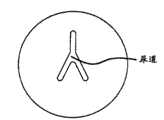
In addition, in a preferred embodiment, an element of second anchoring piece realizes that in the mode of pin pin has first end and second end, and first end is provided with a pair of isolated arm, and second end limits flat pipe.
And, also expect employed different replacement method.Promptly, in application more of the present invention, the present invention can be used for helping body fluid to have a mind to or by mistake flows through the inner chamber of health, change the size and the shape of bodily lumen or chamber, the treatment prostate increases, the treatment urinary incontinence, the location of support or tissue, organ or graft, realization is improved looks and is drawn and lifted or reseting procedure, forms blood vessel and connects, and/or treat the various other diseases that natural fabric or pathological tissues or organ are pressed in the anatomical structure of contiguous anatomical structure or obstruction vicinity.And the present invention has that other very many potential surgical operations are used, treatment application, cosmetic applications or reconstruction application, and for example, tissue, organ, implant or other materials need the situation regaining, draw and lift, reset, compress or support.
In one or more embodiment, disclosed device can have compact arbor wheel exterior feature, and for example, the arbor wheel exterior feature can fit into the cystoscope sheath of the 19F that patient can receive under clear-headed situation.This device has hard distal shaft and comes manual compression tissue at intervention position by the handle with the bar operation tool so that allow.In special explanation, the spring driving needle can be set up the independent degree of depth, and the size that pierces through the urethra-prostate distance of main quantity.The pin that the automatic setting of anatomical structure is passed in expectation can pierce through reliably with enough power and speed.And this device can be provided with the structure that the manual withdrawal pin of tactile feedback is provided to user.This has also simplified the machinery that the selection of regaining pin is provided, and causes placing in tissue after pin is regained first and second anchoring elements.
In addition, this device can be provided with the stitching guiding piece that promising stitch provides centering, and/or stop member, so that keep stitch stable, anchoring piece is placed thereon to guarantee the reliable assembling of anchoring assembly simultaneously.In addition, the auto-tensioning spring is set for when bar is regained and activates, thereby stable stitch tension force is provided when anchoring piece is set up, and makes anchoring piece more stably in place, and make the distance of two anchoring piece diameters minimum, and keep destination organization by approaching.And the prevention sheet of means of delivery axocoel and spring-like was used to before being provided with the anchoring piece of distal-most end is held in place, and the means of delivery axocoel has the anchoring piece that at least one flat aligned surfaces is alignd and will be alignd with the stitch of tensioning.Then, the actuating of last trigger is moved pusher element, so that utilize enough speed and the power that is held in place reliably advances on the stitch anchoring piece.
According to following detailed explanation, (, illustrate principle of the present invention) in conjunction with the accompanying drawings by example, other feature and advantage of the present invention will become clear.
Description of drawings
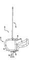
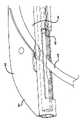
Fig. 1 is a left side view, and an embodiment of anchoring piece induction system is shown;
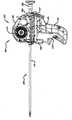
Fig. 2 is a perspective view, and the anchoring piece induction system of Fig. 1 is shown;
Fig. 3 is a right side view, and the anchoring piece induction system of Fig. 1 is shown;
Fig. 4 is a side view, and the anchoring piece induction system of Fig. 3 is shown, and the part of its middle shell is removed;
Fig. 5 is that attempt in the left side; The anchoring piece induction system of Fig. 1 is shown, and the part of its middle shell is removed;
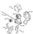
Fig. 6 is an exploded view, and the device of Fig. 1 is shown;
Fig. 7 is a perspective view, pin is shown drives core assembly;
Fig. 8 is other perspective view, and the pin that Fig. 7 is shown drives core assembly;
Fig. 9 is an exploded view, and the pin that Fig. 7 is shown drives core assembly;
Figure 10 is a zoomed-in view, and the part that pin drives core assembly is shown;
Figure 11 amplifies to attempt, and illustrates and is connected to the part that pin drives the needle assembly of core assembly;
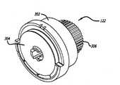
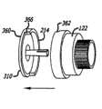
Figure 12 is a perspective view, and the cartridge type assembly of conveyer device is shown;
Figure 13 is the perspective view that was rotated, and the cartridge type assembly of Figure 12 is shown;
Figure 14 is an exploded view, and the element of cartridge type assembly is shown;
Figure 15 is a side view, and first element of anchoring piece and anchor delivery system is shown;
Figure 16 is a perspective view, and the element that the element of Figure 15 is connected to the cartridge type assembly is shown;
Figure 17 is a perspective view, and the cartridge type assembly of replacement in the anchoring piece induction system is shown;
Figure 18 is a perspective view, and other elements that the cartridge type assembly are connected to the anchoring piece induction system are shown;
Figure 19 is a perspective view, illustrate loading from the part of the anchoring assembly of cartridge type assembly so that be passed in needle assembly in the conveyer device;
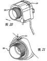
Figure 20 is a perspective view, illustrates to relate to the other step of loading the cartridge type assembly;
Figure 21 is a perspective view, and the other step of loading the cartridge type assembly is shown, and relates to the far-end that a part that makes anchoring assembly advances to conveyer device;
Figure 22 is a cutaway view, and the first step that relates to intervention procedure is shown;
Figure 23 is a phantom, and the conveyer device that is in the deactivated structure is shown;
Figure 24 is the perspective view that part is analysed and observe, and the terminal far away of conveyer device is shown;
Figure 25 is a phantom, the conveyer device actuator is shown presses down;
Figure 26 is a phantom, the conveyer device actuator is shown separates;
Figure 27 is the perspective view that part is analysed and observe, and needle assembly is shown partly ejects;
The perspective view that Figure 28 partly analyses and observe illustrates needle assembly and ejects fully;
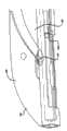
Figure 29 is a cutaway view, is illustrated in the intervention position needle assembly and advances;
Figure 30 is a phantom, and the conveyer device that is in SBR is shown;
Figure 31 is a phantom, and the actuator that conveyer device is shown presses down;
Figure 32 is a phantom, and the action of the element of conveyer device when actuator presses down is shown;
Figure 33 is a phantom, and the bar that induction system is shown presses down fully;
Figure 34 is the perspective view that part is analysed and observe, and the needle assembly that leaves connector is shown is contracted;
Figure 35 is a cutaway view, and first element that is illustrated in the intervention position anchoring assembly is transferred;
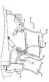
Figure 36 is a phantom, and the position relation of the inner member of induction system when actuator activates is shown;
Figure 37 is a phantom, and the other action of the inner member of conveyer device is shown;
Figure 38 is a phantom, and the other action that also has of the inner member of conveyer device is shown;
Figure 39 is a side view, and the element that pin drives core assembly is shown;
Figure 40 is a cutaway view, and the element that pin drives core assembly is shown;
Figure 41 is a side view, and the action of the element of core assembly is shown;
Figure 42 is a cutaway view, the state after the structure that Figure 41 is shown activates;
Figure 43 is a perspective view, and the element that the cartridge type assembly is shown engages with the element of pin driven unit;
Figure 44 is a perspective view, and the element actuation motion subsequently of Figure 43 is shown;
Figure 45 is a perspective view, and the other action of element after the action of regaining bar of Figure 43 is shown;
Figure 46 is a perspective view, and the other action that also has of the element of Figure 43 is shown;
Figure 47 is a perspective view, and the shaft assembly of conveyer device is shown;
Figure 48 is a perspective view, and the structure that limits scope mount is shown;
Figure 49 is that perspective view closes phantom, and the sheath installation component is shown;
Figure 50 is a perspective view, and the cutting assembly of conveyer device is shown;
Figure 51 is a perspective view, and the terminal of the cutting assembly of Figure 50 is shown;
Figure 52 is a perspective view, and the pusher assembly of conveyer device is shown;
Figure 53 is a perspective view, and the trigger assembly of conveyer device is shown;
Figure 54 is an exploded view, and the element of the trigger assembly of Figure 53 is shown;
Figure 55 is a phantom, is illustrated in the withdrawal bar and presses down conveyer device before;
Figure 56 is a phantom, is illustrated in the withdrawal bar and presses down conveyer device afterwards;
Figure 57 is a phantom, and the other action of element of the device of Figure 56 is shown;
Figure 58 is part (secondary) cutaway view, and the action of trigger assembly is shown;
Figure 59 is a phantom, and the conveyer device that preparation presses down the proximal anchors actuator is shown;
Figure 60 is a phantom, and the proximal anchors actuator that the device shown in Figure 59 is shown presses down;
Figure 61 is a phantom, is illustrated in the proximal anchors actuator and presses down the action of the inner member of conveyer device afterwards;
Figure 62 is a perspective view, second anchoring element is shown advances and engage with connector;
Figure 63 is a cutaway view, is illustrated in second anchoring element release in the intervention position;
Figure 64 is a phantom, and the other action that also has of the intraware of conveyer device is shown;
Figure 65 is a perspective view, and the cutting connector is shown;
Figure 66 is a cutaway view, is illustrated in the release of the anchoring assembly of assembling in the intervention position;
Figure 67 is a cutaway view, is depicted as the intervention position of treatment;
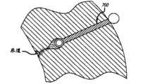
Figure 68 is a cutaway view, is illustrated in the implantation of company's song anchoring assembly at intervention position place; And
Figure 69 is that the part amplification of Figure 68 is attempted.
The specific embodiment
With reference now to accompanying drawing (providing),, the present invention relates to be arranged to carry anchoring piece to enter the intravital device of patient by example and limiting examples.As mentioned above, the medical purpose that disclosed equipment is different, include but not limited to bounce back, draw and lift, push, approaching, support or the tissue that resets, organ, anatomical structure, graft or other materials of in the patient body, finding.This organized processing is used to make the treatment disease easier.And the present invention is applied to beauty treatment or restores purpose, or is applied to and the relevant field of medical treatment research and development.
One special aspect, anchoring assembly of the present invention is contemplated can be by ultrasound wave and visual mechanism.Therefore, during at ultrasonic swept-volume (for example, when ultrasound wave passes rectum usually), anchoring piece can be in sight when the medical professional diagnoses or treats the relevant situation of similar carcinoma of prostate.
In one aspect of the invention, the part of anchoring assembly or implantation piece is positioned and is implanted to first against anatomical structure.Then, the second portion of contiguous anatomical structure is located or be implanted to the second portion of anchoring assembly or implantation piece also, so that for the first with respect to anatomical structure regain, draw and lift, push, approaching, support or the second portion of the anatomical structure that resets, and for the second portion with respect to anatomical structure regain, draw and lift, push, approaching, support or the first of the anatomical structure that resets.It should further be appreciated that, because the first by being fixed to anchoring assembly and implantation piece and the coupling assembling of second portion offer its tension force, the first of anchoring assembly and second portion can be configured to perform the expectation of anatomical structure withdrawal, draw and lift, push, approaching, support or reset.
With reference now to Fig. 1-3,, an embodiment ofdevice 100 is shown.This device is configured to be included in the internal energy structure that also can assemble and implant one or more anchoring assemblies or implantation piece near intervention position of patient body.In one aspect,device 100 is configured to utilize interchangeable cartridge type parts assembling and implants independent anchoring assembly or implantation piece.If user has been replaced the cartridge type parts, so other anchoring assembly or implantation piece can assembled and implantation.This device also is contemplated and can uses with the 19F sheath.In addition, this device comprises and is configured to receive existing remote reviewing device (for example, endoscope) so that the structure that the step that the intervention position place carries out can be observed.
Anchoringpiece conveyer device 100 comprises and is connected to theHandleset 102 of elongated tissue near assembly 104.Size can fit into the tolerant 19F cystoscope of patient sheath elongated tissue holds the measure of the original paper that is used to form anchoring assembly and rather than general anesthesia clear-headed patient nearassembly 104 during.Tissue is inflexible to allow coming the manual squeezing tissue in the leverage of intervention position by handle assembly near assembly.
Anchoringpiece conveyer device 100 also comprises a plurality of parts.Comprise that thehandle housing assembly 106 that cooperates handle portion surrounds handle assembly 102.The size and dimension ofhandle assembly 102 is made into cosily to be engaged in operator's the hands and can be formed by existing material.Can in handlehousing assembly 106, form window so that the approach of internal mechanism near device to be provided, thereby the operator can cancel manually under the situation that the intervention measure is abandoned.
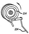
In one embodiment,conveyer device 100 is provided with multiple brake component, and actuated piece is of value to assembling and the conveying of carrying out anchoring assembly at intervention position.Be provided withpin actuator 108 and be discussed in more detail below,pin actuator 108 makes needle assembly (first element with anchoring assembly) advance to intervention position.In a preferred embodiment, needle assembly has pin, and pin moves and leave the needle assembly that aligns with handle component along warp rail, in special embodiment, aligns with handle.In other different embodiment, the pin shell is orientated to respect to vertical handle being at 2 or 10 and locates to leave shell.Pin also is set regainsbar assembly 110, and when it activated, cause the needle assembly withdrawal and expose first anchoring element.This action and the structure that relate to also are discussed in more detail below.At last,conveyer device 100 is provided with the rear anchor piece actuating assembly or the proximalanchors actuating assembly 112 of complete description below, when activating, rear anchor piece actuating assembly or proximalanchors actuating assembly 112 realize second element is assembled into the release of anchoring assembly and realization anchoring assembly at intervention position.
With reference now to Fig. 4-6,, a plurality of parts ofconveyer device 100 are introduced into, and the function and the structure of each of these parts describe in detail below.In described embodiment,housing unit 106 has three mating parts, lefttop shell 114, bottomleft housing 116 and right shell body 118.Within the scope of the invention, housing unit can be made of a plurality of parts.Except cooperating to surround parts, housing parts comprises structure member, to provide rigidity and to the support of besieged parts.
Pin is regainedcore assembly 120 andcartridge type assembly 122 is accommodated in the housing unit 106.The nook closing member parts is identical with the axis of cartridge typeassembly.Shaft assembly 124 comprises the part that is positioned athousing unit 106 and the part of extending from the front end of housingunit.Trigger assembly 126 is connected toshaft assembly 124 and is associated with shaft assembly 124.Figure 4 and 5 illustrate the juxtaposition relationship of different parts, and Fig. 6 is the exploded view that parts are shown.
With reference to figure 7-9, this embodiment of the structure of nook closing member parts is shown.As described in detail below, pin is regainedcore assembly 120 and is regained dried the cooperation with pin actuator and pin, so that at intervention position needle assembly is advanced, regains needle assembly then.
It is the cramped constructions that comprise a plurality of moving members that pin is regained core assembly 120.Needle spring shell 202 forms a side ofassembly 120 and is set to vicinity nook closing member portion housing 204.The outside ofneedle spring shell 202 forms basic plane and circular depressions is formed on the opposite side of needle spring housing 202.During form after pin is regainedcore assembly 120 and taked to assemble, the circular depressions ofneedle spring housing 202 is in the face of nook closing member portion housing 204.Two extra basic circular depressions are formed in the opposite side of nook closingmember portion housing 204.
Thepin configuration spring 206 that is configured in pin configuration spring bornwork arbor 208 interior and contiguous pin configuration spring bornwork arbors 208 is betweenneedle spring housing 202 and the nook closingmember portion housing 204 and in the circular depressions of facing mutually that is formed on wherein, and pin configuration spring bornwork arbor 208 is adjacent to pin clutch discs 210.Then, pinclutch discs 210 is adjacent to and is formed on the center of circle recess in the pinclutch cup 212 and is received in wherein.Nook closingmember portion 214 is received in the nook closingmember portion housing 204, and nook closingmember portion housing 204 is recesses relative with needle spring housing 202.Pin configuration spring 206 is used to rotate nook closingmember portion 214 and is used to utilize power and speed that the end of pin is stretched out and passes tissue.In a method, wish thatdevice 100 is configured to make that pin is used to the independent degree of depth, so that pierce through the predetermined cohort of urethra-prostate distance.
Each of almost circularpin configuration spring 206 and pin configuration spring bornwork arbor 208 all comprises central through hole.In addition,clutch push rod 216 extend through from the outside ofneedle spring housing 202 assembly of finishing alignment the hole and extend throughpin configuration spring 206 and pin configuration spring born work arbor 208.As interacting and be discussed in more detail below by regaining bar with pin, theclutch actuator 218 that is configured in the pivot on the outer surface ofneedle spring housing 202 cause that pushrod 216 laterally moves in case its in conjunction with and spring bornwork arbor 208 isolating true clutch discs 210.Pin axle 206 is disposedspring 206 bias voltage rotationally by pin, andpin configuration spring 206 can be formed by the motor spring that helically is provided with.Also be provided with needlespring replacement bar 220, it can be used to the spring bornwork arbor 208 of resetting after initial the use.
As described,clutch discs 210 is received in the pin clutch cup 212.The inside ofclutch cup 212 comprises protruding (not shown), and the size of projection can cooperate the corresponding recess that is formed in the clutch discs 210.In addition, the size that is formed on the centre bore in theclutch discs 210 can receive the newel that extends from the adjacent face of clutch discs.This structure is of value to the complementary rotation ofclutch discs 210 and clutch cup 212.The complementary rotation ofclutch cup 212 and nook closingmember portion 214 is pierced through the interconnecting of centre bore that is formed in the nook closingmember portion housing 204 by these and is realized.
This assembly also comprisespin ratchet 222, and pin operationally links to each other with the pin actuator with ratchet.As described below and shown in, the pin actuator pivots pin and breaks away from and the engaging of spring bornwork arbor 208 withratchet 222, thereby allows its rotation.
Shown in Figure 10 and 11, the size and dimension of the near-end 230 of needle assembly can form with other structures and be connected.In a method, the near-end of needle assembly comprises that size and dimension can receive the interior shoulder of corresponding recess of the periphery that is formed on nook closing member portion 214.Other methods that realize to connect also are designed so that to engage the recess in the end that is formed on needle assembly and needle assembly is held in place with respect to nook closing member portion with the shear line (not shown).By this connection, the rotation of nook closingmember portion 214 can be determined the advance length and the withdrawal length of needle assembly.In this respect, shown in Figure 10 and 11, the peripheral recess that forms in nook closingmember portion 214 is configured to occupy the length of needle assembly.
The details ofcartridge type assembly 122 has been shown in Figure 12-14.Almost circularstitching core sleeve 302 forms the external structure of cartridge type assembly122.Tension spring 308 and sew upcore 310 and be between thestitching core track 304 of basic dish type and themain knob 306 and be in the stitching core sleeve ofcartridge type assembly 122 of assembling.As described below,tension spring 300 is used for providing tension force on the connector (for example, stitch) at anchoring assembly.Various cartridge type assembly can be set, and its concrete form is the spring with relative differential tension.And this system can be arranged to different tension force is provided when connector is advanced, and subsequently anchoring assembly is arranged on intervention position.Sewing upcore 310 is configured to engage releasedly and pulls out ratchet 224.But also being provided withknob follower 312 andwire clamp 314, its function is described below.
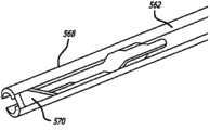
Figure 15 illustrates thedistal anchors 350 of anchoring assembly and a form of connector 352.In the proximal end of anchoring assembly, has the impeller 354 (for example, the stainless steel wire of coated with PTFE) that to be arranged to be connected to connector 352 (for example, PET monofilament stitch) by sleeve (for example, polyimides sleeve) 356.Be fixed to the terminal (seeing Figure 16) of vicinity of theimpeller 354 ofstitch core 304 by wire clamp 314.Provide the annular space that centers onstitch core 304 so that receive the length ofimpeller 354.
With reference now to Figure 17-21,, the special benefits of this embodiment is thatcartridge type assembly 122 is removable and interchangeable.In a preferred embodiment, the door on housing can be opened, and the door of opening can be arranged in the housing so that approach near the inside of conveyer device is provided.Alternately, lefttop shell 114 can be removed, so that the approach near the inside of conveyer device is provided.When replacing,cartridge type assembly 122 can be set in the outer recess ofcore shell 204, and formation engages with nook closing member portion 214.The newel that extends from nook closingmember portion 214 helps to guide thecartridge type assembly 122 perpendicular to nook closing member portion 214.The shoulder 360,362 that is respectively formed on nook closingmember portion 214 and thecartridge type assembly 122 is guaranteed alignment suitably between parts.Illustrate best as Figure 19, the guiding terminal 364 of anchoring assembly stretches out fromcartridge type shoulder 362, and the length of beginning assembly is configured to around sewing up core.The terminal 364 of assembly is alignd with thehole 366 in theshoulder 360 that is formed on nook closing member portion and is inserted in this hole.
In case insert, themain knob 306 ofcartridge type assembly 122 rotates (Figure 20-21) so that make the guiding terminal of anchoring assembly and advance and passhole 366 in the coupling part, passes the length (seeing Figure 10-11) of needle assemblythen.Main knob 306 is rotated further up to 312 arrival of knob follower and finishes a little, thus expression: and the anchoring assembly bending is loaded in the needle assembly, and in one embodiment, the leading end of anchoring assembly is the distal openings of contiguous pin just.
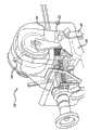
The treatment prostate special, an infinite use in (seeing Figure 22),, the elongated tissue of conveyer device is positioned at the urethra (UT) of the bladder (UB) that leads to patient near part 104.Elongatedportion 104 advances in the patient body and arrives prostate (PG) up to itsleading end 400.
As shown in figure 23,conveyer device 100 was configured to be in the SBR in thisstage.Pin actuator 108 is rotatedbias assembly 402 spring bias voltages.Pin actuator safety member (not shown) can be included to just pintrigger 108 is locked in stop position.When pin actuator 108 pressed down, lockingcam assembly 404 rotated 90 degree, allowed pin to regainbar 110 thus and activated subsequently.Assembly also compriseslever lock 406, and the pin that lever lock is configured to keep pressing down afterbar 110 is regained is regainedbar.Terminal 400 at theelongated portion 104 of this stage conveyer device is also held theneedle assembly 410 of thorough withdrawal, and comprises that the second anchoring assembly element, 450, the second anchoring assembly elements are aligned so that use (seeing Figure 24) subsequently.
The original paper that initially the pressing down ofpin actuator 108 causes biasassembly 402 pivot (seeing Figure 25).Dischargingpin actuator 108 helps it to be returned as pressed status and allows lockingcam assembly 404 to rotate 90 to spend (seeing Figure 26).In this position, lockingcam assembly 404 is oriented to allow pin to regainbar 110 actuatings.
Shown in Figure 27 and 28, at leadingend 400 places of conveyer device, this action causes needle assembly to advance in elongated member 104.As should be understood, the direction that the direction of extending with Handleset in this embodiment is identical ejects pin by pin configuration spring 206.And needle assembly can be configured to return along bending to handle because of it ejects.When the prostate intervention position uses (seeing Figure 29),needle assembly 410 advances and passes and exceed prostate (PG).The end of using spring to help to guarantee pin is passed prostatic tough and tensile external bladder rapidly, and does not have " filling in " capsule or pierce through capsule.In an alternative embodiment, user can manually use pin.In a method, pin 410 forms and applies Parylene by the Nitinol pipe.This coating helps to remedy wearing and tearing or environmental loss (that is, steam), and wearing and tearing or environmental loss can reduce the effect of needle-penetration.
With reference to figure 30-32, the action of the internal part ofconveyer device 100 whenpin actuator 108 activates has been described.Figure 30 shows thepin actuator 108 that is in non-actuated condition.Pin actuator 108 (Figure 31) as described, its rotation, and its extension joint pin is with ratchet 222.The continuing to press down of pin actuator (Figure 32) causes thatpin ratchet 222 engages from itself and pin configuration spring bornwork arbor 208 and begins rotation.Then, this disengaging allowspin configuration spring 206 to rotate pin and rotates (see figure 9) withaxle 208,clutch discs 210, pinclutch cup 212 and nook closing member portion 214.The rotation of pin configuration spring bornwork arbor 208 can be by noting needlespring replacement bar 220 the variation of position realize.And, by with being connected of needle assembly, the rotation of nook closingmember portion 214 causes the needle assembly predetermined distance of advancing.
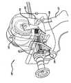
Then, press down fully and after pin regainedbar 110 releases, pin is regainedbar 110 can activated (seeing Figure 33) fully at pin actuator 108.When such actuating,lever lock 406 engages the also bar 110 of locks in place.Can be operated onetime trip lever 110 after the lever lock 406.This action causesneedle assembly 410 withdrawals, thereby theconnector 352 of anchoring assembly is stayed extended position (seeing Figure 34).When extending, connector extends through the pin window and enters by sewing up guide structure.As shown in figure 35, in prostate intervention measure, cause first anchoring element or far-end anchoring element are configured to surpass the outer surface of prostate (PG) equally, andconnector 352 extends to theterminal 400 of conveyer device.
Inconveyer device 100, the actuating that pin is regainedbar 110 causes that theclutch actuator 218 of pivot rotates (seeing Figure 31-38).As shown in figure 36,clutch actuator 218 is in original position.When bar 110 activated,clutch actuator 218 rotated (seeing Figure 37).
As illustrating best among Figure 39-42, the rotation of the clutch actuator of pivot causes the bar surfaceengagement push rod 216 of its inclination.Then, this causes thatpush rod 216 horizontal moving againstclutch discs 210 and with spring bornwork arbor 208 break away from.This subsequently disengaging causes nook closingmember portion 214 is configured to allow regainbar 110 and the manual withdrawal needle assembly by the operation pin, and is configured to provide tension force on the connector of anchoring assembly.The tactile feedback that the manual withdrawal of pin provides the method for simplification and offers the operator is regained fully so that determine pin.Should be realized that the operation that the disengaging of pin configuration spring allows pin to regainbar 110 is endurable for patient, and does not almost have the instrument of conveyer device tomove.Tension spring 308 provides tension force, and this helps to guarantee that distal anchors is pulled becomes and firmly contact of predetermined tissue plane (for example, prostatic external capsule surface).Obviously, the spring of preferred embodiment provides predetermined power, for example reaches 1-2 pound or more tension force.In a further embodiment, spring can be used for automatically regaining needle assembly.
Pin is regained and the time of tensioning realizes by the interaction of pulling out ratchet 224 and nook closing member portion 214.Shown in Figure 43 and 44, to pull out ratchet 224 and be configured to allow nook closing member portion to clockwise rotate, this is depressed into to pull out at the pin actuator and takes place when ratchet 224 is aligned in the groove that forms in the nook closing member portion.The actuating that pin is regained bar 110 causes pulls out ratchet 224 bendings (also part Figure 38), and this makes pulls out ratchet 224 and separate with nook closing member portion 214.Because nook closing member portion 214 separates with aforesaid spring born work arbor in this position, allow pin axle 214 along rotating with counter clockwise direction shown in Figure 46.This rotating counterclockwise lasts till that pulling out ratchet 224 aligns once more and be formed in the nook closing member portion 214 in the recess 516 that forms (seeing Figure 46).This recess can be spaced apart so that the predetermined corresponding pin degree of depth is provided.And this structure can be equipped with roller-clutch part (not shown), and this provides the continuous process that vertically moves.The tension spring of cartridge type assembly 122 (seeing Figure 14) then automatically provides stable tension on the connector of anchoring assembly.At the abutment, connector is drawn into sews up guide frame 411 (seeing Figure 34) so that with connector centering, and is ready to engage with second anchoring assembly.This tension force causes the far-end or first anchoring element 350 undesirably to be positioned at intervention position (as shown in figure 35), and the distance between two anchoring elements of the feasible anchoring assembly of implanting is minimum.And, can be different from tension force in the course of conveying of connector of anchoring assembly at the tension force that anchoring element 350 is produced after in place.
The more detailed description of shaft assembly and trigger assembly meets the explanation of the operation of trigger assembly, thus realize second or the near-end anchoring element be assembled into the connector of anchoring assembly and discharge whole anchoring assembly at intervention position.
With reference to Figure 47, the embodiment of shaft assembly 12 is shown.As disclosed before, trigger assembly (describing below) is mounted toshaft assembly 124, andshaft assembly 124 comprises the element that is positioned atdevice case assembly 106 and from the structure of its extension.Theterminal part 400 ofshaft assembly 124 comprises atraumatic most advanced and sophisticated sleeve pipe 502.Tubular shafts assembly 504 is arranged at most advanced andsophisticated sleeve pipe 502 contiguously, and most advanced and sophisticated telescopic size and dimension is made for and receives needle assembly slidably.The distal portions oftubular shafts assembly 504 is crooked, so that the direction from its pin that stretches out along the arm that corresponds essentially to conveyer device is extended.Be configured to below and longitudinally adjacenttubular shaft assembly 506 are elongatedlids 507, the size of this lid can receive the elongated portion of cutting assembly and pusher assembly.
Near-end atshaft assembly 124 is a scope mount lock(ing) bolt assembly 508.Sheath installation component 510 comprises that locked withbolts part 512 and scope mount assembly are at far-end and longitudinally-spaced.The arrangements of components of cuttingassembly 514 andpusher assembly 516 is between these assemblies.But, should be appreciated that cutting assembly and pusher assembly comprise the elongated portion to far-end 400 extensions ofshaft assembly 124.
As shown in figure 48, scope mount lock(ing)bolt assembly 508 comprises the locked withbolts part 520 that contiguousscope mount receptor 522 is provided with rotationally.The scope mount assembly comprises that also the handle pusher supports cooperation fastener member 524.Illustrate best at first as Fig. 3-5, scope mount locking ground engagesmirror 550, and mirror has the longitudinal size of the length that is enough to thebasic mirror pipe 506 of longitudinal extension.
Sheath installedpart 510 can be threaded io the elongated portion (seeing Figure 49) of shaft assembly.Sheath installedpart 510 can comprise sealingmember 530, and sealing member is used for sealing and minimizing the fluid of the handle portion that enters conveyer device.
Illustrate best as Figure 50 and 51, the embodiment of cuttingassembly 514 comprises the cuttingplate 560 that supports the sensing far-end, elongated cuttingpipe 562 and guide 564.Also be provided with a pair ofspring extension 566 and each all is arranged to be connected to the cutting spring.The far-end 568 of cuttingpipe 562 disposes sword, makes that in case cut thespring cutting assembly 514 that is allowed to withdraw, sword can cut the connector of the expectation of anchoring assembly.
With reference to Figure 52, the embodiment of thepusher assembly 516 ofshaft assembly 124 has been described.Pusher assembly 516 comprises the elongated impeller 580 that extends to pusher extension 584 from pusher piece 582.As described in greater detail, pusher extension 584 engages the near-end of second anchoring element or near-end anchoringelement.Propeller piece 582 also comprises the size and dimension of a plurality of recesses 586, so that accept the corresponding structure of trigger assembly.
The details of the embodiment of trigger assembly 126 is described in Figure 53 and 54.Assembly 126 comprises bottom 602 and framework 604, and other assemblies are fixed or are supported on them.Bar pivotal part 606 is connected to proximal anchors actuator 608 rotationally.As described below, bar pivotal part 606 turns to the second position by the action of bar from primary importance, and primary importance place bar pivotal part fixedly prevents from back or proximal anchors actuator 608 to activate, and second position place can make the proximal anchors actuator activate.The last actuating of proximal anchors actuator 608 causes trigger 610 bendings, and trigger discharges the trigger 612 with cam surface.Also be provided with first ratchet 614, and it is configured to against two cam faces of trigger 612 and enters be formed on the as above disclosed recess that forms in the propeller piece of propulsion component.As described below, second ratchet 616 is followed the action of first ratchet 614, so that engage the propeller piece as expected.Sickle ratchet 618 also is arranged to the cam with trigger 612, and the cutting click-fit is so that activate cutting assembly.And trigger assembly 126 also comprises replacement bar 620 and comprises the emergent assembly 622 of sickle of biasing spring 624 that the operation of biasing spring will be described in the Xiamen.But, should be noted that this system for example can be configured to, pin is regained the replacement and the emergency function of the operation energy finishing device of bar.
With reference to figure 55-58, in the mode of cutaway view the embodiment of anchoring piece conveying is shown, so that the latch-up structure and the unlocking structure oftrigger assembly 126 are described.In Figure 55,pin actuator 108 and pin are regained the position that bar 110 is in deactivated, and barpivotal part 606 locking pressbutton pad assembly 608 in primary importance activated preventing.When pin actuator 108 presses down and activatewithdrawal bar 110 subsequently (seeing Figure 56), the 606 rotation disengagings of bar pivotal part engage with proximal anchors actuator 608.In this stage, 608 releases of proximal anchors actuator also can be lowered (seeing Figure 57).In case reduce, proximal anchors actuator 608 vertically movestrigger 610 is rotated away from the locking oftrigger 612 and engages.Then, this has started the action oftrigger assembly 126.
With reference to Figure 59, thetrigger assembly 126 before activateding is shown.As directed, proximal anchors actuator 608 is ready to press down, and trigger 612 is in its vertical remote location.Andfirst ratchet 614 is in primary importance and engages (also seeing Figure 58) withpusher 582 lockings of pusher assembly.
As mentioned above, press proximal anchors actuator 608 to discharge trigger612.By spring assembly 650 bias voltages, when discharging, trigger 612 moves (seeing Figure 60) with respect to the operator at near-end.Because it moves at near-end, the cam face ontrigger 612 rotates first ratchet andpusher assembly 582 is disengaged.This action causes the pusher assembly to discharge (also seeing Figure 52), so that longitudinally move along distal direction.The control that vertically moves of pusher assembly is kept bysecond ratchet 616, and second ratchet is followed moving of first ratchet, and first ratchet rotates so that at this many tops pusher 662.
So the release of pusher assembly realizes making pusher in distal advancement, this causes second element 450 of anchoring assembly to advance forming engaging (seeing Figure 62) with the locking of the connector of anchoring assembly.This action causes that with reliable retentivity pusher 582 makes anchoring element 450 to be enough to that anchoring piece 450 speed and power in place are advanced on the connector (for example stitch).In the patient body, shown in Figure 63, anchoring assembly is configured to across anatomical structure in the intervention position.Then, the cutting cam face that is formed on the vertical setting on the trigger 612 engages cutting ratchet 618 subsequently so that it is rotated breaks away from and the engaging of cutting assembly, thereby makes the action of its spring that utilizes the bias voltage cutting assembly and be contracted (seeing Figure 64).When cutting assembly was withdrawn, its blade divided 570 (seeing Figure 51 and 65) to form across connector 352, thereby at second anchoring element, 450 adnexaes it is cut off.Figure 65,68 and 69 illustrates the implanted anchoring assembly 700 of formation.Figure 68 has described the phantom of the urethra (UT) that broadens owing to the prostata tissue that amplifies around the anchoring assembly extruding, because outer lens capsule tissue is quite hard, incompressible and can not move, and prostatic adenoma and urethra wall energy are compressed and can be moved.By comparing, Figure 67 has described the phantom of the non-treatment intervention position of the urethra (UT) that narrows down owing to the prostata tissue that amplifies on every side.
Shown in Figure 62 and 65,conveyer device 100 can be configured to keep and use a plurality of second anchoring elements 450.Anchoringelement 450 is along the straight line setting and the length of the used anchoring piece of being arranged to make independent anchoring element because each trigger-actuated is advanced.When the trigger assembly replacement, next sequenced anchoring element is prepared to be used.In this respect, the far-end sheet 710 thatlid 507 can dispose spring-like, sheet 710 engage and are formed on second the slit to the anchoring element of farthest position, and sheet 710 help to keep before use farthest the suitable location of anchoringpiece.Lid 507 can further be provided with near-end and sew up the slit (not shown) and comprise and be arranged to comprise the inside (see Figure 62) of at least one flat aligned surfaces so that anchoringelement 450 is alignd with connector 352.And the far-end of conveyer device can be provided with the lid of flexible/elastic.This lid protection anchoring piece usage space is so that guarantee that reliable anchoring piece is positioned on the connector and the permission Herba Ophioglossi ejects from means of delivery.In Figure 65, the far-end of conveyer device is shown in the cystoscope sheath 712.
Second anchoring element can be embodied as the slotted anchoring piece that is configured to fixed connecting piece.Slotted proximal anchors can comprise flat tubulose rear end, and this rear end is being similar to flat pipe in shape, and the horizontal sectional width that has is greater than its rear end.Slotted proximal anchors comprises that also a pair of isolated rear end from slotted proximal anchors extends to the tip of the front end of slotted near-end tippy tea.The engagement position that isolated tip begins at groove together.The shape and size of the structure of tip and perception prevent the tip bending substantially.Tip comprises towards interior protuberance, and protuberance is configured to catch and make the connector bending, and prevents connector in case engage the joint that just breaks away from slotted anchor.The connection of the stitch of assembly and intensity mechanism are the combinations of the fracture on the extruding of the stitch between the hard slotted tip of anchoring piece and the surrounding edge by slotted, the flat tubular anchor firmware surface that makes stitch.Surrounding edge provides the chuck of anchoring piece and the contact surface zone, bottom between the stitch, and compression stress is concentrated on the focus, and focus causes that stitch centers on inner recesses and exterior face.Should be further appreciated that various other embodiment of the anchoring piece that also it is contemplated that the slotted anchoring piece that forms clip or slotless.Especially, can utilize thereby provide the various embodiment of alternative method structure to be connected to connector.That is, anchoring piece structurally can be deformable, flexible, sealing, embedded, fusile and/or coiling.
Therefore, the present invention designed directly that anchorage part at anchoring assembly promotes and between just anchoring assembly connector on promote.And as mentioned above, the far-end anchoring element or first anchoring element advance by needle assembly and are utilized, and at least one element of the near-end anchoring element or second anchoring element advances and is utilized from the housing parts of the used device of anchoring piece.In addition, independent anchoring assembly or a plurality of anchoring assembly can be transferred and be used at intervention position by inking device.As a result, under the prostatic situation of treatment, the present invention is used for compressed prostate and opens prostatic urethra, carries between implantation piece and the end at implantation piece at intervention position to apply tension force.And, also consider and carry out drug conveying, and drug conveying is described as the other treatment of BPH, activates treatment and treatment carcinoma of prostate and the prostatitis of bladder again.
In case implant, anchoring assembly of the present invention is finished operation, compression or the withdrawal of desirable tissue and is cooperated so that AT supporting construction is provided with target anatomical structure.In a preferred embodiment, the shape of anchoringassembly 700 and profile are configured to by utilizing anchoring assembly to open the urethra chamber, and assembly moves in destination organization, (sees Figure 68-69) in the natural gauffer that for example forms in urethra.In fact, in the situation that anchoring assembly is suitably placed, the very thin or softish tissue in the zone is weak round anchoring assembly.At last, natural fabric can be grown on anchoringassembly 700, and the cell of shape growth in time continuity and (seeing Figure 69) take place.Help rehabilitation and avoid undesirable side effect with this being combined with of destination organization, for example, in calcification of intervention position place or infection.
Disclosed anchoring piece conveyer device can be arranged to multipurpose or independent purposes.In this respect, the first a plurality of or independent anchoring element can be loaded by the cartridge type assembly in conveyer device, and the cartridge type assembly is that can remove and interchangeable assembly.In addition, the second a plurality of or independent anchoring element can be arranged in the shaft assembly, and is for example shown in Figure 34.In this respect, second anchoring element can align to ground, end at the shaft assembly inner end, and second anchoring element of most proximal end is configured to engage with the leading end of pusher assembly.
In addition, after using for the first time, the core assembly of conveyer device can be reset, and (sees Figure 30-32,36-38) so that re-use by operation replacement bar 220.The initial step of reset apparatus relates to and discharges engage (the seeing Figure 33) that pin is regainedbar 110 and locking mechanism 406.In addition, trigger assembly can be reset by the actuator oftrigger replacement bar 620.
Have been noted that under certain conditions being transferred in intervention position (Figure 35) at first anchoring element needs the sickle assembly 622 (seeing Figure 54/58 and 59) of meeting an urgent need afterwards.When needs, theemergent assembly 622 of sickle causes decontroling the sickle ratchet, thereby discharges cutting component, and cuts the connector of anchoring assembly subsequently before anchoring piece is assembled fully.Wish that in the present invention the ability that at any time can both regain pin comprises that catching the pin that moves also regains the pin that is provided with for fully.
And, except being used for cooperating, the invention still further relates to fast track rehabilitation or reduce the method for wound with the natural fabric anatomical structure.The mode that rehabilitation therein can be promoted can comprise the use grinding-material, fabric connector, biological preparation and medicine.
Observe the position that anchoring piece is arranged on the various hope in the anatomical structure and can obtain optimum efficiency.For example, when the treatment prostate, the part of anchoring assembly can be arranged in the urethra and in second element, surpass prostatic outer surface.Have been found that by the far-end of use device and implant anchoring assembly, so that laterosurtrusion in office moves lobes of prostate (tension spring presents relaxed state in connector after delivery needle is retracted simultaneously), (when the axis of urethra is observed) is supported or keep second anchoring element to be set simultaneously so that the position on ten o'clock and two, keeps anatomical structure open and also help the anchoring piece part to move in natural fabric effectively.Near the anatomical regions bladder this situation in junction surface that deferent duct therein is connected to urethra that neutralizes exists especially.
In addition, wish that whole elements of anchoring assembly or the part of (be described or any anchoring assembly of conceiving) selection can apply or insert with therapeutant or diagnostic substances (for example, medicine or therapeutic agent).And under the prostatic situation of treatment, anchoring assembly can apply with the material of for example 5-Alpha-reductase or insert, and this material causes that prostatic size reduces.Other materials of design include but not limited to plant chemical ingredient, normally Alpha-1a-adrenoceptor end-capping reagent, smooth muscle relaxant, and prevent that testosterone is converted into the medicament of dihydrotestosterone.In a special method, connector 95 for example can be coated with polymer matrix or gelinite coating, and polymer matrix or gelinite coating keep therapeutant or diagnostic substances and help to finish its periodic release.In addition, wish that fungistatic coating and other chemical native cities that are used for the treatment of prostatitic analgesic and antibiotic and are used for the treatment of cancer can put on the different piece of anchoring assembly described herein.These coatings can have different thickness and concrete thickness, make it cooperate the profile of the cylindrical part of the anchoring piece that is fixed to connector with connector self.And, the treatment gel of the common conveying by implantation piece inking device or other medical apparatus and instruments volumes (for example catheter) and diagnosis gel or other materials, and the anchoring assembly that comprises them belongs to scope of the present invention, as as radio device device (for example, the far-end or the other treatment form of implantation piece of capsule or treatment cancer).In a this method, inking device comprises the bin that keeps gelatinous mass, and by this bin, anchor can advance so that obtain the treatment gelatinous mass or the diagnosis gelatinous mass of scheduled volume.
Should be appreciated that the progressive time of needle assembly and connector assembly and subsequently between these assemblies relative motion be adjusted.That is, needle assembly at first provides the passage near intervention position, and the connector assembly extends beyond the terminal of needle assembly by the relative motion of needle assembly and connector assembly then.
Wish also that in certain embodiments the anchoring piece conveyer device can comprise the power that detection applies thus or the ability of other environmental conditions.The different piece of this device comprises this device, and can be set up along needle assembly in the method pick off of an anticipation.In this case, the operator can survey, and for example, whether pin destroys the scope in the target anatomical structure of intervention position and the generation of this destruction.The other reasons that can survey the special environment feature also can be as for example blood or other chemicals or other component sensors.And, when carrying or after implanting, imagine one or more pressure transducers or pick off, so that the feedback of the configuration status of anchoring assembly is provided.In addition, this pick off can be incorporated anchoring assembly self into, in other structures or anatomical structure of inking device.
And, should notice that aforesaid process is reversible.In a method, the link of anchoring assembly can be cut off and remove near-end (or second) anchoring element from patient body.For example, the doctor can cut connector simply, removes second anchoring piece that (for example, utilize employed electrosurgery device, surgery device or laser surgery device in carrying out transurethral prostatic resection and) initially implanted simultaneously.
The aspect of different embodiments of the invention provides the ability of carrying a plurality of anchoring assemblies (having customizable length) and far-end anchoring element, and each anchoring assembly is implanted and need not remove this device from patient at diverse location.Different embodiment provides the different pin degree of depth and different connector length for each of a plurality of anchoring assemblies of being transferred.Other aspects of different embodiments of the invention are conveyings based on load (preferred 1 pound) of anchoring assembly, wherein this device has the connector of incorporating into, the conveying of the anchoring assembly of (for example stitch) cutting member and wherein have the conveying of the anchoring assembly of endoscope in the device.Conveyer device is configured to load (half pound to five pounds) is placed between isolated first anchoring piece and between first anchoring piece of implanting and the conveyer device or on first anchoring piece and conveyer device implanted uniquely, first anchoring piece implanted in case help to determine first anchoring element securely against tissue plane (for example, prostatic external capsule) and since second anchoring element be connected to connector and be held relatively securely.In this respect, can be connected to the mechanism that when needle assembly is regained, between different anchoring assemblies, produces predetermined tension ordinatedly as the needle assembly that pierces through element.And this load can realize between the first and second implanted anchoring pieces.
Should be appreciated that different materials is in the scope of the present invention, so that the operation disclosed device.And one or more elements (for example distal anchors of one or more anchors disclosed herein, proximal anchors, connector) can be designed to completely or partially biodegradable or biolytic.
In addition, as described, apparatus and method disclosed herein can be used for treating the multiple disease in multiple inner chamber that comprises chamber or wall or tissue.The example of this inner chamber or tissue includes but not limited to pelvis, stomach, esophagus, trachea, bronchial, blood vessel (for example, being used for the treatment of varix or valvular insufficiency), tremulous pulse, lymphatic vessel, urethra, bladder, heart cup or atrium, uterus, fallopian tube etc.
Finally, should be appreciated that, described the present invention in the above, but different increase, deletion, change and modifications can be made those examples and embodiment, and not deviate from the spirit and scope of the present invention with reference to definite example of the present invention or embodiment.For example, any element and the characteristics Ke Bin of embodiment or example incorporate another embodiment or example into, or use with another example or embodiment, unless do embodiment or example or inappropriate purposes that can cause not having patentability like this.And for example, under the situation that the special order of the step 1 of method is illustrated or lists, the order of these steps can be changed, and method or the inappropriate application that causes not having patentability done in punishment like this.All reasonably increase, delete, revise and replace the equivalent that is considered to described example and embodiment, and are included in the scope of following claim.
Therefore, according to aforementioned content, obviously can make different modifications, and not deviate from the spirit and scope of the present invention, special form of the present invention is illustrated and describes simultaneously.
Claims (46)
1. one kind is used for the treatment of systemic system, and it comprises:
Anchoring assembly, this anchoring assembly comprises anchoring piece and connector; And
Conveyer device, this conveyer device comprise needle assembly and cartridge type assembly, and this cartridge type assembly holds the anchoring piece and the connector of anchoring assembly;
Wherein, the cartridge type assembly is fed in the needle assembly with one in anchoring piece in the anchoring assembly and the connector and the cartridge type assembly is interchangeable.
2. the system as claimed in claim 1, wherein, a plurality of cartridge type assemblies with different elastic hardnesses can be connected to conveyer device.
3. the system as claimed in claim 1, wherein, the part of anchoring assembly is in the cartridge type assembly, and other parts of anchoring assembly are in the outer conveyer device of cartridge type assembly.
4. the system as claimed in claim 1, wherein, the cartridge type assembly comprises spring.
5. system as claimed in claim 4, wherein, described system provides first tension force when anchoring assembly advances, and this first tension force is different from second tension force after carrying anchoring assembly.
6. system as claimed in claim 4, wherein, conveyer device comprises actuator, the actuating of actuator allows spring assembly to apply tension force on first element of anchoring assembly and in second element at least one.
7. the system as claimed in claim 1, wherein, conveyer device comprises the core needle assembly.
8. system as claimed in claim 7, wherein, the core needle assembly comprises clutch part.
9. system as claimed in claim 7, wherein, conveyer device also comprises a needle assembly, thus, by regaining the operability contact of bar, core needle assembly control needle assembly advances or regains.
10. system as claimed in claim 9, wherein, the core needle assembly comprises the spring relevant with the operation of needle assembly.
11. system as claimed in claim 10, wherein, conveyer device comprises first actuator, and the actuating of first actuator allows spring to make needle assembly advance automatically.
12. system as claimed in claim 11, wherein, conveyer device comprises second actuator, and the actuating of second actuator causes the needle assembly manual withdrawal.
13. system as claimed in claim 12, wherein, conveyer device comprises clutch part, and thus, the actuating of second actuator causes that clutch part makes the part of core needle assembly separate with pin configuration spring.
14. the system as claimed in claim 1, wherein, the cartridge type assembly is with the anchoring piece and the connector feeding process needle assembly of anchoring assembly.
15. the system as claimed in claim 1, wherein, needle assembly can twine around core assembly.
16. system as claimed in claim 15, wherein, the part of anchoring assembly is twined around core cartridge type assembly.
17. system as claimed in claim 16, wherein, the cartridge type assembly comprises the 3rd actuator, the actuating of the 3rd actuator with the anchoring assembly feeding in needle assembly.
18. system as claimed in claim 17, wherein, the 3rd actuator of cartridge type assembly comprises from terminating shut-down mechanism, make the 3rd actuator rotational fixation amount and cause anchoring assembly to be positioned at precalculated position in the needle assembly, wherein, the 3rd actuator does not allow anchoring assembly to be advanced further or to regain.
19. system as claimed in claim 18, wherein, conveyer device comprises trigger assembly, and this trigger assembly is configured to realize the assembling of anchoring assembly.
20. system as claimed in claim 19, wherein, conveyer device comprises emergent assembly, and this emergent assembly is configured to allow a part of cutting off anchoring assembly before removing means of delivery from patient by required at anchoring assembly.
21. one kind is used for the treatment of systemic system, it comprises:
Anchoring assembly, this anchoring assembly comprise first element and second element; And
Conveyer device, this conveyer device comprise needle assembly, pin is with actuator and regain bar;
Wherein, actuator is finished the actuation configuration of needle assembly, and regains bar and finish the manual withdrawal needle assembly.
22. system as claimed in claim 21, wherein, conveyer device comprises pin configuration spring, and the power that the actuating of actuator causes the utilization of pin configuration spring to be enough to penetration of target tissues is advanced needle assembly automatically.
23. the system as claimed in claim 22, wherein, the manual withdrawal of needle assembly is finished in the actuating of regaining bar.
24. system as claimed in claim 23, wherein, conveyer device comprises the core assembly of the position of controlling needle assembly.
25. system as claimed in claim 24, wherein, core assembly comprises pin configuration spring.
26. system as claimed in claim 25, wherein, conveyer device comprises the cartridge type assembly, and this cartridge type assembly holds an anchoring element.
27. system as claimed in claim 26, wherein, the cartridge type assembly is interchangeable.
28. system as claimed in claim 27, wherein, the cartridge type assembly is configured to engage releasedly core assembly.
29. system as claimed in claim 28, wherein, the cartridge type assembly is configured to a described anchoring element feeding in needle assembly.
30. system as claimed in claim 29, wherein, the cartridge type assembly comprises spring.
31. system as claimed in claim 30, wherein, clutch part is configured to separate the cartridge type assembly from least a portion of core assembly.
32. system as claimed in claim 31, wherein, spring is configured to apply tension force on a described anchoring element.
33. system as claimed in claim 32, wherein, conveying arrangement comprises trigger assembly.
34. system as claimed in claim 33, wherein, trigger assembly is configured to realize the assembling of anchoring assembly.
35. system as claimed in claim 34, wherein, trigger assembly control is to the three-element cut-out of anchoring assembly.
36. system as claimed in claim 35, wherein, conveyer device comprises emergent assembly, and emergent assembly is configured to cut off the three element of anchoring assembly.
37. system as claimed in claim 36, wherein, conveyer device comprises the first replacement bar, this first replacement bar core needle assembly that is configured to reset.
38. system as claimed in claim 37, wherein, conveyer device comprises the second replacement bar, and this second replacement bar is configured to the trigger assembly of resetting.
39. one kind is used for the treatment of systemic system, it comprises:
Anchoring assembly; And
Conveyer device, this conveyer device comprise needle assembly, core assembly, trigger assembly, first actuator, second actuator and the 3rd actuator;
Wherein, the actuating of first actuator is advanced the part of anchoring assembly and needle assembly, and the actuating of second actuator makes the needle assembly withdrawal, and the assembling of anchoring assembly is finished in the actuating of the 3rd actuator.
40. system as claimed in claim 39, wherein, conveyer device comprises the first replacement bar and the second replacement bar, the first replacement bar replacement core assembly wherein, the second replacement bar replacement trigger assembly.
41. system as claimed in claim 40, wherein, conveyer device comprises emergent assembly, and the cut-out to the element of anchoring assembly is finished in the actuating of emergent assembly.
42. system as claimed in claim 39, wherein, conveyer device comprises closing assembly, closing assembly with rod lock after first actuator presses down.
43. system as claimed in claim 39, wherein, conveyer device comprises locking mechanism, and locking mechanism is at the pressed status securing rod.
44. system as claimed in claim 39, wherein, conveyer device comprises first actuator lock, and first actuator lock prevents unexpected configuration pin.
45. system as claimed in claim 39, wherein, conveyer device comprises avoids the 3rd actuator by the too early mechanism that uses up to second actuator presses down fully.
46. the system as claimed in claim 1, wherein, pin moves along the warp rail in the needle assembly.
Applications Claiming Priority (3)
| Application Number | Priority Date | Filing Date | Title |
|---|---|---|---|
| US8493708P | 2008-07-30 | 2008-07-30 | |
| US61/084,937 | 2008-07-30 | ||
| PCT/US2009/052271WO2010014821A2 (en) | 2008-07-30 | 2009-07-30 | Anchor delivery system with replaceable cartridge |
Publications (2)
| Publication Number | Publication Date |
|---|---|
| CN102112064Atrue CN102112064A (en) | 2011-06-29 |
| CN102112064B CN102112064B (en) | 2014-06-18 |
Family
ID=41137066
Family Applications (1)
| Application Number | Title | Priority Date | Filing Date |
|---|---|---|---|
| CN200980130076.3AActiveCN102112064B (en) | 2008-07-30 | 2009-07-30 | Anchor delivery system with replaceable cartridge |
Country Status (5)
| Country | Link |
|---|---|
| US (2) | US8216254B2 (en) |
| EP (3) | EP2345374B1 (en) |
| JP (2) | JP5571079B2 (en) |
| CN (1) | CN102112064B (en) |
| WO (1) | WO2010014821A2 (en) |
Cited By (17)
| Publication number | Priority date | Publication date | Assignee | Title |
|---|---|---|---|---|
| CN104248456A (en)* | 2013-06-28 | 2014-12-31 | 柯惠Lp公司 | Articulating Device with Timing System for Endoscopic Operations |
| CN104964143A (en)* | 2015-07-01 | 2015-10-07 | 肖叶 | Silver needle bar placing table |
| US9504461B2 (en) | 2005-05-20 | 2016-11-29 | Neotract, Inc. | Anchor delivery system |
| CN107233142A (en)* | 2016-10-08 | 2017-10-10 | 武汉奥绿新生物科技股份有限公司 | A kind of hyperplastic tissue's intervention therapeutic apparatus |
| US10105132B2 (en) | 2005-05-20 | 2018-10-23 | Neotract, Inc. | Devices, systems and methods for treating benign prostatic hyperplasia and other conditions |
| CN109310417A (en)* | 2016-04-01 | 2019-02-05 | 伊西康有限责任公司 | Surgical stapling system including transmitting device can be shifted |
| US10426509B2 (en) | 2005-05-20 | 2019-10-01 | Neotract, Inc. | Median lobe destruction apparatus and method |
| US10492792B2 (en) | 2005-05-20 | 2019-12-03 | Neotract, Inc. | Devices, systems and methods for treating benign prostatic hyperplasia and other conditions |
| CN110584853A (en)* | 2019-11-13 | 2019-12-20 | 微创优通医疗科技(上海)有限公司 | Operating system, implant delivery system and delivery method |
| US10912637B2 (en) | 2013-03-14 | 2021-02-09 | Neotract, Inc. | Devices, systems and methods for treating benign prostatic hyperplasia and other conditions |
| US10925587B2 (en) | 2005-05-20 | 2021-02-23 | Neotract, Inc. | Anchor delivery system |
| US10945719B2 (en) | 2005-05-20 | 2021-03-16 | Neotract, Inc. | Devices, systems and methods for retracting, lifting, compressing, supporting or repositioning tissues or anatomical structures |
| CN112638283A (en)* | 2018-07-16 | 2021-04-09 | 乌巴特·奥贾克 | Suturing member, suturing needle and suturing device |
| CN113853169A (en)* | 2019-06-11 | 2021-12-28 | 波士顿科学国际有限公司 | Device for increasing force distribution at suture-tissue interface |
| US11298115B2 (en) | 2020-08-03 | 2022-04-12 | Teleflex Life Sciences Limited | Handle and cartridge system for medical interventions |
| US11331093B2 (en) | 2012-06-29 | 2022-05-17 | Teleflex Life Sciences Limited | Flexible system for delivering an anchor |
| US11672520B2 (en) | 2017-12-23 | 2023-06-13 | Teleflex Life Sciences Limited | Expandable tissue engagement apparatus and method |
Families Citing this family (77)
| Publication number | Priority date | Publication date | Assignee | Title |
|---|---|---|---|---|
| ES2279156T3 (en) | 2002-06-11 | 2007-08-16 | Tyco Healthcare Group Lp | MALE TIGHTS FOR HERNIAS. |
| US8926637B2 (en) | 2003-06-13 | 2015-01-06 | Covidien Lp | Multiple member interconnect for surgical instrument and absorbable screw fastener |
| US7670362B2 (en) | 2003-06-13 | 2010-03-02 | Tyco Healthcare Group Lp | Multiple member interconnect for surgical instrument and absorbable screw fastener |
| US10478179B2 (en) | 2004-04-27 | 2019-11-19 | Covidien Lp | Absorbable fastener for hernia mesh fixation |
| US8491606B2 (en)* | 2005-05-20 | 2013-07-23 | Neotract, Inc. | Median lobe retraction apparatus and method |
| US8603106B2 (en) | 2005-05-20 | 2013-12-10 | Neotract, Inc. | Integrated handle assembly for anchor delivery system |
| US8333776B2 (en) | 2005-05-20 | 2012-12-18 | Neotract, Inc. | Anchor delivery system |
| US8425535B2 (en) | 2005-05-20 | 2013-04-23 | Neotract, Inc. | Multi-actuating trigger anchor delivery system |
| US8668705B2 (en) | 2005-05-20 | 2014-03-11 | Neotract, Inc. | Latching anchor device |
| US8945152B2 (en) | 2005-05-20 | 2015-02-03 | Neotract, Inc. | Multi-actuating trigger anchor delivery system |
| US9011473B2 (en) | 2005-09-07 | 2015-04-21 | Ulthera, Inc. | Dissection handpiece and method for reducing the appearance of cellulite |
| US9486274B2 (en) | 2005-09-07 | 2016-11-08 | Ulthera, Inc. | Dissection handpiece and method for reducing the appearance of cellulite |
| US10548659B2 (en) | 2006-01-17 | 2020-02-04 | Ulthera, Inc. | High pressure pre-burst for improved fluid delivery |
| US8518069B2 (en) | 2005-09-07 | 2013-08-27 | Cabochon Aesthetics, Inc. | Dissection handpiece and method for reducing the appearance of cellulite |
| US9358033B2 (en) | 2005-09-07 | 2016-06-07 | Ulthera, Inc. | Fluid-jet dissection system and method for reducing the appearance of cellulite |
| US9028520B2 (en) | 2006-12-22 | 2015-05-12 | The Spectranetics Corporation | Tissue separating systems and methods |
| US8961551B2 (en) | 2006-12-22 | 2015-02-24 | The Spectranetics Corporation | Retractable separating systems and methods |
| US8439940B2 (en) | 2010-12-22 | 2013-05-14 | Cabochon Aesthetics, Inc. | Dissection handpiece with aspiration means for reducing the appearance of cellulite |
| US8944990B2 (en)* | 2008-10-27 | 2015-02-03 | Ams Research Corporation | Surgical needle and anchor system with retractable features |
| US9358064B2 (en) | 2009-08-07 | 2016-06-07 | Ulthera, Inc. | Handpiece and methods for performing subcutaneous surgery |
| US11096708B2 (en) | 2009-08-07 | 2021-08-24 | Ulthera, Inc. | Devices and methods for performing subcutaneous surgery |
| US9855031B2 (en) | 2010-04-13 | 2018-01-02 | Neosurgical Limited | Suture delivery system |
| GB2486497B (en) | 2010-12-17 | 2013-06-19 | Neosurgical Ltd | Laparoscopic trocar system |
| US9161749B2 (en) | 2011-04-14 | 2015-10-20 | Neotract, Inc. | Method and apparatus for treating sexual dysfunction |
| KR20140097107A (en) | 2011-11-01 | 2014-08-06 | 엘지전자 주식회사 | Method for determining the transmission of a sounding reference signal in a wireless communication system, and terminal therefor |
| US10292801B2 (en) | 2012-03-29 | 2019-05-21 | Neotract, Inc. | System for delivering anchors for treating incontinence |
| US9445899B2 (en) | 2012-08-22 | 2016-09-20 | Joseph M. Arcidi | Method and apparatus for mitral valve annuloplasty |
| US9413896B2 (en) | 2012-09-14 | 2016-08-09 | The Spectranetics Corporation | Tissue slitting methods and systems |
| US9358010B2 (en) | 2013-03-12 | 2016-06-07 | Covidien Lp | Flex cable and spring-loaded tube for tacking device |
| US10383691B2 (en) | 2013-03-13 | 2019-08-20 | The Spectranetics Corporation | Last catheter with helical internal lumen |
| US9883885B2 (en) | 2013-03-13 | 2018-02-06 | The Spectranetics Corporation | System and method of ablative cutting and pulsed vacuum aspiration |
| US9283040B2 (en) | 2013-03-13 | 2016-03-15 | The Spectranetics Corporation | Device and method of ablative cutting with helical tip |
| US9456872B2 (en) | 2013-03-13 | 2016-10-04 | The Spectranetics Corporation | Laser ablation catheter |
| US9291663B2 (en) | 2013-03-13 | 2016-03-22 | The Spectranetics Corporation | Alarm for lead insulation abnormality |
| US9867620B2 (en) | 2013-03-14 | 2018-01-16 | Covidien Lp | Articulation joint for apparatus for endoscopic procedures |
| US10835279B2 (en) | 2013-03-14 | 2020-11-17 | Spectranetics Llc | Distal end supported tissue slitting apparatus |
| US9668765B2 (en) | 2013-03-15 | 2017-06-06 | The Spectranetics Corporation | Retractable blade for lead removal device |
| US9918737B2 (en) | 2013-03-15 | 2018-03-20 | The Spectranetics Corporation | Medical device for removing an implanted object |
| US10842532B2 (en) | 2013-03-15 | 2020-11-24 | Spectranetics Llc | Medical device for removing an implanted object |
| US9655621B2 (en) | 2013-03-15 | 2017-05-23 | Covidien Lp | Surgical instrument for dispensing tacks and solution |
| US9980743B2 (en) | 2013-03-15 | 2018-05-29 | The Spectranetics Corporation | Medical device for removing an implanted object using laser cut hypotubes |
| US10448999B2 (en) | 2013-03-15 | 2019-10-22 | The Spectranetics Corporation | Surgical instrument for removing an implanted object |
| WO2014151814A1 (en) | 2013-03-15 | 2014-09-25 | The Spectranetics Corporation | Surgical instrument for removing an implanted object |
| US9358004B2 (en) | 2013-06-28 | 2016-06-07 | Covidien Lp | Articulating apparatus for endoscopic procedures |
| US9351728B2 (en) | 2013-06-28 | 2016-05-31 | Covidien Lp | Articulating apparatus for endoscopic procedures |
| US10085746B2 (en) | 2013-06-28 | 2018-10-02 | Covidien Lp | Surgical instrument including rotating end effector and rotation-limiting structure |
| US20150032130A1 (en) | 2013-07-24 | 2015-01-29 | Covidien Lp | Expanding absorbable tack |
| US9526498B2 (en) | 2013-09-17 | 2016-12-27 | Covidien Lp | Surgical device with a trigger lockout mechanism device |
| EP3113701B1 (en) | 2014-03-03 | 2020-07-22 | The Spectranetics Corporation | Multiple configuration surgical cutting device |
| US12053203B2 (en) | 2014-03-03 | 2024-08-06 | Spectranetics, Llc | Multiple configuration surgical cutting device |
| US10335146B2 (en)* | 2014-04-02 | 2019-07-02 | Coviden Lp | Surgical fastener applying apparatus, kits and methods for endoscopic procedures |
| US10405924B2 (en) | 2014-05-30 | 2019-09-10 | The Spectranetics Corporation | System and method of ablative cutting and vacuum aspiration through primary orifice and auxiliary side port |
| US9877714B2 (en) | 2014-06-04 | 2018-01-30 | Neotract, Inc. | System with reloadable handle for delivering an anchor |
| WO2016126699A1 (en) | 2015-02-02 | 2016-08-11 | On-X Life Technologies, Inc. | Rapid deployment artificial chordae tendinae system |
| USD770616S1 (en) | 2015-02-20 | 2016-11-01 | The Spectranetics Corporation | Medical device handle |
| USD765243S1 (en) | 2015-02-20 | 2016-08-30 | The Spectranetics Corporation | Medical device handle |
| US11090097B2 (en) | 2015-03-17 | 2021-08-17 | Covidien Lp | Connecting end effectors to surgical devices |
| US11103350B2 (en) | 2016-06-01 | 2021-08-31 | On-X Life Technologies, Inc. | Pull-through chordae tendineae system |
| US10617409B2 (en) | 2016-10-21 | 2020-04-14 | Covidien Lp | Surgical end effectors |
| US11298123B2 (en) | 2016-10-21 | 2022-04-12 | Covidien Lp | Surgical end effectors |
| US10743859B2 (en) | 2016-10-21 | 2020-08-18 | Covidien Lp | Surgical end effectors |
| US10888309B2 (en) | 2017-01-31 | 2021-01-12 | Covidien Lp | Surgical fastener devices with geometric tubes |
| WO2018223324A1 (en)* | 2017-06-08 | 2018-12-13 | Covidien Lp | Adjustable rotation assembly for surgical instruments |
| GB2565573A (en) | 2017-08-17 | 2019-02-20 | Creo Medical Ltd | Interface joint for an electrosurgical apparatus |
| WO2019182645A1 (en) | 2018-03-23 | 2019-09-26 | Conmed Corporation | Suture anchor driver |
| US11298126B2 (en) | 2018-05-02 | 2022-04-12 | Covidien Lp | Shipping wedge for end effector installation onto surgical devices |
| US11116500B2 (en) | 2018-06-28 | 2021-09-14 | Covidien Lp | Surgical fastener applying device, kits and methods for endoscopic procedures |
| CN110327129A (en)* | 2019-04-25 | 2019-10-15 | 卢乐 | Restorer for the operation of ox abomasal displacement |
| US11523817B2 (en) | 2019-06-27 | 2022-12-13 | Covidien Lp | Endoluminal pursestring device |
| USD944985S1 (en) | 2019-12-19 | 2022-03-01 | Covidien Lp | Positioning guide cuff |
| US11197675B2 (en) | 2019-12-19 | 2021-12-14 | Covidien Lp | Positioning guide for surgical instruments and surgical instrument systems |
| USD944984S1 (en) | 2019-12-19 | 2022-03-01 | Covidien Lp | Tubular positioning guide |
| WO2021168057A1 (en) | 2020-02-21 | 2021-08-26 | Neotract, Inc. | Apparatus for preventing device deployment failure |
| US12357443B2 (en)* | 2020-08-31 | 2025-07-15 | Cedars Health Inc. | Benign prostatic hyperplasia treatment device |
| KR102170400B1 (en)* | 2020-08-31 | 2020-10-27 | 정윤호 | Prostate enlargement treatment device |
| US20230034746A1 (en)* | 2021-07-29 | 2023-02-02 | Cook Medical Technologies Llc | Medical Devices That Include a Trigger Assembly for a Rotatable Catheter and Methods of Use |
| CN118717287B (en)* | 2023-10-12 | 2025-08-29 | 合肥易联立通医疗科技有限公司 | Surgical system and its anchor delivery system, magazine and robotic arm |
Family Cites Families (334)
| Publication number | Priority date | Publication date | Assignee | Title |
|---|---|---|---|---|
| US2734299A (en)* | 1956-02-14 | Igudolph | ||
| US659422A (en)* | 1900-06-12 | 1900-10-09 | George W Shidler | Surgical instrument. |
| US789467A (en)* | 1903-06-12 | 1905-05-09 | Stillman A West | Method of tying knots. |
| US780392A (en)* | 1903-09-14 | 1905-01-17 | Brown Straw Binder Company | Straw-bundle tie. |
| US2579192A (en)* | 1950-08-15 | 1951-12-18 | George H Sciaroni | Suturing instrument |
| US2697624A (en)* | 1951-11-03 | 1954-12-21 | John A Thomas | Portable knot tying device |
| US2646298A (en)* | 1952-07-15 | 1953-07-21 | Joseph C Leary | Method of knot tying |
| US2825592A (en)* | 1954-01-06 | 1958-03-04 | Semple James Mckenzie | Portable knot tying device for smooth filaments |
| US3326586A (en)* | 1965-07-09 | 1967-06-20 | Robert M Frost | Snell knot tying tool |
| US3470834A (en)* | 1968-03-08 | 1969-10-07 | Dennison Mfg Co | Fastener attaching device |
| US3521918A (en)* | 1968-08-14 | 1970-07-28 | Richard L Hammond | Fishline knotting fixture and cutter |
| US3664345A (en)* | 1970-07-06 | 1972-05-23 | Clyde Harwell Dabbs | Surgical buttons |
| US3716058A (en)* | 1970-07-17 | 1973-02-13 | Atlanta Res Inst | Barbed suture |
| US3713680A (en)* | 1971-02-09 | 1973-01-30 | S Pagano | Knot typing device for barrel knots |
| US3756638A (en)* | 1972-02-22 | 1973-09-04 | L Stockberger | Knot tyer |
| US3875648A (en)* | 1973-04-04 | 1975-04-08 | Dennison Mfg Co | Fastener attachment apparatus and method |
| US3873140A (en)* | 1973-10-15 | 1975-03-25 | Moodus Sports Products | Fish hook holder and knot tying device |
| US3931667A (en)* | 1974-05-08 | 1976-01-13 | Dennison Manufacturing Company | Interlocking attachment device |
| US3976079A (en)* | 1974-08-01 | 1976-08-24 | Samuels Peter B | Securing devices for sutures |
| US4006747A (en)* | 1975-04-23 | 1977-02-08 | Ethicon, Inc. | Surgical method |
| US4235238A (en)* | 1978-05-11 | 1980-11-25 | Olympus Optical Co., Ltd. | Apparatus for suturing coeliac tissues |
| US4210148A (en)* | 1978-11-03 | 1980-07-01 | Stivala Oscar G | Retention suture system |
| DE2853289C2 (en)* | 1978-12-09 | 1980-12-18 | B. Braun Melsungen Ag, 3508 Melsungen | Button for surgical use |
| US4409974A (en)* | 1981-06-29 | 1983-10-18 | Freedland Jeffrey A | Bone-fixating surgical implant device |
| US4513746A (en)* | 1981-10-09 | 1985-04-30 | United States Surgical Corp. | Instrument for applying plastic-like surgical fastening devices |
| US5417691A (en) | 1982-05-20 | 1995-05-23 | Hayhurst; John O. | Apparatus and method for manipulating and anchoring tissue |
| US4741330A (en)* | 1983-05-19 | 1988-05-03 | Hayhurst John O | Method and apparatus for anchoring and manipulating cartilage |
| US6656182B1 (en) | 1982-05-20 | 2003-12-02 | John O. Hayhurst | Tissue manipulation |
| US4823794A (en)* | 1982-07-12 | 1989-04-25 | Pierce William S | Surgical pledget |
| US5435805A (en)* | 1992-08-12 | 1995-07-25 | Vidamed, Inc. | Medical probe device with optical viewing capability |
| US5370675A (en)* | 1992-08-12 | 1994-12-06 | Vidamed, Inc. | Medical probe device and method |
| US4493323A (en)* | 1982-12-13 | 1985-01-15 | University Of Iowa Research Foundation | Suturing device and method for using same |
| US4621640A (en)* | 1984-01-09 | 1986-11-11 | Mulhollan James S | Mechanical needle carrier and method for its use |
| US4657461A (en)* | 1984-10-26 | 1987-04-14 | Smith Gareth J | Anchoring bolt |
| US4750492A (en)* | 1985-02-27 | 1988-06-14 | Richards Medical Company | Absorbable suture apparatus, method and installer |
| US4955913A (en)* | 1985-03-28 | 1990-09-11 | Robinson Walter C | Surgical tie |
| US4669473A (en)* | 1985-09-06 | 1987-06-02 | Acufex Microsurgical, Inc. | Surgical fastener |
| US4705040A (en)* | 1985-11-18 | 1987-11-10 | Medi-Tech, Incorporated | Percutaneous fixation of hollow organs |
| US4738255A (en)* | 1986-04-07 | 1988-04-19 | Biotron Labs, Inc. | Suture anchor system |
| US5123914A (en)* | 1986-05-19 | 1992-06-23 | Cook Incorporated | Visceral anchor for visceral wall mobilization |
| US4762128A (en)* | 1986-12-09 | 1988-08-09 | Advanced Surgical Intervention, Inc. | Method and apparatus for treating hypertrophy of the prostate gland |
| US4714281A (en)* | 1987-01-02 | 1987-12-22 | Peck Richard M | Device and method for tying a twisted clinch knot |
| US4744364A (en)* | 1987-02-17 | 1988-05-17 | Intravascular Surgical Instruments, Inc. | Device for sealing percutaneous puncture in a vessel |
| US4898156A (en)* | 1987-05-18 | 1990-02-06 | Mitek Surgical Products, Inc. | Suture anchor |
| US4899743A (en)* | 1987-12-15 | 1990-02-13 | Mitek Surgical Products, Inc. | Suture anchor installation tool |
| US4968315A (en)* | 1987-12-15 | 1990-11-06 | Mitek Surgical Products, Inc. | Suture anchor and suture anchor installation tool |
| US4926860A (en)* | 1988-02-05 | 1990-05-22 | Flexmedics Corporation | ARthroscopic instrumentation and method |
| US5053046A (en)* | 1988-08-22 | 1991-10-01 | Woodrow W. Janese | Dural sealing needle and method of use |
| US5904679A (en) | 1989-01-18 | 1999-05-18 | Applied Medical Resources Corporation | Catheter with electrosurgical cutter |
| JP2722132B2 (en)* | 1989-05-03 | 1998-03-04 | 日機装株式会社 | Device and method for alleviating stenosis from the lumen |
| US4946468A (en)* | 1989-06-06 | 1990-08-07 | Mitek Surgical Products, Inc. | Suture anchor and suture anchor installation tool |
| US5002550A (en)* | 1989-06-06 | 1991-03-26 | Mitek Surgical Products, Inc. | Suture anchor installation tool |
| RU2062121C1 (en) | 1989-10-13 | 1996-06-20 | Давыдов Владимир Александрович | Dilating device |
| US5919202A (en) | 1989-12-05 | 1999-07-06 | Yoon; Inbae | Surgical instrument with jaws and movable internal needle and method for use thereof |
| US5267960A (en) | 1990-03-19 | 1993-12-07 | Omnitron International Inc. | Tissue engaging catheter for a radioactive source wire |
| US5080660A (en)* | 1990-05-11 | 1992-01-14 | Applied Urology, Inc. | Electrosurgical electrode |
| US5236445A (en)* | 1990-07-02 | 1993-08-17 | American Cyanamid Company | Expandable bone anchor and method of anchoring a suture to a bone |
| US5269809A (en)* | 1990-07-02 | 1993-12-14 | American Cyanamid Company | Locking mechanism for use with a slotted suture anchor |
| US5041129A (en)* | 1990-07-02 | 1991-08-20 | Acufex Microsurgical, Inc. | Slotted suture anchor and method of anchoring a suture |
| US5203787A (en)* | 1990-11-19 | 1993-04-20 | Biomet, Inc. | Suture retaining arrangement |
| US5129912B2 (en)* | 1991-01-07 | 2000-01-11 | Urohealth Systems Inc | Device and method for applying suture |
| US5100421A (en)* | 1991-02-05 | 1992-03-31 | Cyprus Endosurgical Tools, Inc. | Christoudias curved needle suture assembly |
| DE4106823C1 (en)* | 1991-03-04 | 1992-06-25 | Liebscher Kunststofftechnik, 8032 Graefelfing, De | |
| US5405352A (en)* | 1991-04-09 | 1995-04-11 | Weston; Peter V. | Suture knot, method for its formation and use, and knot forming apparatus |
| US5217470A (en)* | 1991-04-29 | 1993-06-08 | Weston Peter V | Apparatuses and methods for formation and use of a slipknot as a surgical suture knot |
| US5258015A (en)* | 1991-05-03 | 1993-11-02 | American Cyanamid Company | Locking filament caps |
| US5234454A (en)* | 1991-08-05 | 1993-08-10 | Akron City Hospital | Percutaneous intragastric balloon catheter and method for controlling body weight therewith |
| US5861002A (en) | 1991-10-18 | 1999-01-19 | Desai; Ashvin H. | Endoscopic surgical instrument |
| US5411520A (en)* | 1991-11-08 | 1995-05-02 | Kensey Nash Corporation | Hemostatic vessel puncture closure system utilizing a plug located within the puncture tract spaced from the vessel, and method of use |
| CA2181674A1 (en) | 1991-12-03 | 1993-10-04 | Theodore V. Benderev | Support structure for supporting and positioning medical equipment |
| US5217486A (en)* | 1992-02-18 | 1993-06-08 | Mitek Surgical Products, Inc. | Suture anchor and installation tool |
| US5364408A (en)* | 1992-09-04 | 1994-11-15 | Laurus Medical Corporation | Endoscopic suture system |
| US5540704A (en)* | 1992-09-04 | 1996-07-30 | Laurus Medical Corporation | Endoscopic suture system |
| US5578044A (en)* | 1992-09-04 | 1996-11-26 | Laurus Medical Corporation | Endoscopic suture system |
| US6048351A (en) | 1992-09-04 | 2000-04-11 | Scimed Life Systems, Inc. | Transvaginal suturing system |
| US7060077B2 (en) | 1992-09-04 | 2006-06-13 | Boston Scientific Scimed, Inc. | Suturing instruments and methods of use |
| US5322501A (en)* | 1992-10-02 | 1994-06-21 | Mahmud Durrani Ayaz | Continent urethral stent for treating and preventing urethral stricture after surgery |
| US5368599A (en)* | 1992-10-08 | 1994-11-29 | United States Surgical Corporation | Surgical fastening apparatus with suture array |
| IL103737A (en) | 1992-11-13 | 1997-02-18 | Technion Res & Dev Foundation | Stapler device particularly useful in medical suturing |
| US5370646A (en)* | 1992-11-16 | 1994-12-06 | Reese; H. William | Bone clamp and installation tool |
| US5814073A (en) | 1996-12-13 | 1998-09-29 | Bonutti; Peter M. | Method and apparatus for positioning a suture anchor |
| US5380334A (en)* | 1993-02-17 | 1995-01-10 | Smith & Nephew Dyonics, Inc. | Soft tissue anchors and systems for implantation |
| US5735861A (en) | 1995-09-06 | 1998-04-07 | Wilson-Cook Medical, Inc. | Channel mounted activating mechanism for an endoscopic ligator |
| US5334200A (en)* | 1993-03-02 | 1994-08-02 | Lanny L. Johnson | Suture knot making device and method for use |
| US5330488A (en)* | 1993-03-23 | 1994-07-19 | Goldrath Milton H | Verres needle suturing kit |
| SE505436C2 (en) | 1993-04-27 | 1997-08-25 | Ams Medinvent Sa | prostatic stent |
| US5549630A (en) | 1993-05-14 | 1996-08-27 | Bonutti; Peter M. | Method and apparatus for anchoring a suture |
| US5845645A (en) | 1993-05-14 | 1998-12-08 | Bonutti; Peter M. | Method of anchoring a suture |
| US5403348A (en)* | 1993-05-14 | 1995-04-04 | Bonutti; Peter M. | Suture anchor |
| US5472446A (en)* | 1993-06-02 | 1995-12-05 | De La Torre; Roger A. | Surgical instrument for tying a knot in a length of suture at a remote location |
| US5716368A (en) | 1993-06-02 | 1998-02-10 | General Surgical Innovations, Inc. | Knotmaker with curved elongate member used in tying a ligature |
| US5505735A (en)* | 1993-06-10 | 1996-04-09 | Mitek Surgical Products, Inc. | Surgical anchor and method for using the same |
| US5500000A (en) | 1993-07-01 | 1996-03-19 | United States Surgical Corporation | Soft tissue repair system and method |
| US5921982A (en)* | 1993-07-30 | 1999-07-13 | Lesh; Michael D. | Systems and methods for ablating body tissue |
| US5499994A (en)* | 1993-07-30 | 1996-03-19 | American Medical Systems, Inc. | Dilation device for the urethra |
| US5391182A (en)* | 1993-08-03 | 1995-02-21 | Origin Medsystems, Inc. | Apparatus and method for closing puncture wounds |
| US5354271A (en)* | 1993-08-05 | 1994-10-11 | Voda Jan K | Vascular sheath |
| CA2124651C (en)* | 1993-08-20 | 2004-09-28 | David T. Green | Apparatus and method for applying and adjusting an anchoring device |
| US5507754A (en)* | 1993-08-20 | 1996-04-16 | United States Surgical Corporation | Apparatus and method for applying and adjusting an anchoring device |
| US5899911A (en) | 1993-08-25 | 1999-05-04 | Inlet Medical, Inc. | Method of using needle-point suture passer to retract and reinforce ligaments |
| US5417690A (en)* | 1993-09-20 | 1995-05-23 | Codman & Shurtleff, Inc. | Surgical cable |
| US5536273A (en) | 1993-12-09 | 1996-07-16 | Lehrer; Theodor | Apparatus and method of extracorporeally applying and locking laparoscopic suture and loop ligatures |
| AU1011595A (en) | 1994-01-13 | 1995-07-20 | Ethicon Inc. | Spiral surgical tack |
| US5690677A (en) | 1994-02-17 | 1997-11-25 | Arthrex, Inc. | Method for installing a suture anchor through a cannulated tissue-shifting guide |
| CA2141911C (en) | 1994-02-24 | 2002-04-23 | Jude S. Sauer | Surgical crimping device and method of use |
| US5545178A (en)* | 1994-04-29 | 1996-08-13 | Kensey Nash Corporation | System for closing a percutaneous puncture formed by a trocar to prevent tissue at the puncture from herniating |
| US5470337A (en)* | 1994-05-17 | 1995-11-28 | Moss; Gerald | Surgical fastener |
| US5630824A (en) | 1994-06-01 | 1997-05-20 | Innovasive Devices, Inc. | Suture attachment device |
| US5573540A (en)* | 1994-07-18 | 1996-11-12 | Yoon; Inbae | Apparatus and method for suturing an opening in anatomical tissue |
| US5501690A (en)* | 1994-09-02 | 1996-03-26 | Ethicon Endo-Surgery | Suturing device |
| US5545171A (en)* | 1994-09-22 | 1996-08-13 | Vidamed, Inc. | Anastomosis catheter |
| US5531763A (en)* | 1994-10-07 | 1996-07-02 | United States Surgical Corporation | Suture cinching apparatus |
| US5480406A (en)* | 1994-10-07 | 1996-01-02 | United States Surgical Corporation | Method of employing surgical suturing apparatus to tie knots |
| US5554162A (en)* | 1994-12-02 | 1996-09-10 | Delange; Gregory S. | Method and device for surgically joining luminal structures |
| IL111985A (en) | 1994-12-14 | 1999-04-11 | Medical Influence Technologies | Staple and thread assembly particularly for use in power-driven staplers for medical suturing |
| US5665109A (en) | 1994-12-29 | 1997-09-09 | Yoon; Inbae | Methods and apparatus for suturing tissue |
| US5550172A (en)* | 1995-02-07 | 1996-08-27 | Ethicon, Inc. | Utilization of biocompatible adhesive/sealant materials for securing surgical devices |
| RU2112571C1 (en) | 1995-04-11 | 1998-06-10 | Педдер Валерий Викторович | Method for treatment of chronic prostatitis and device for its realization (variants) |
| US5593421A (en) | 1995-06-06 | 1997-01-14 | Bauer; William | Suture element delivery device and method |
| US6117161A (en) | 1995-06-06 | 2000-09-12 | Li Medical Tecnologies, Inc. | Fastener and fastening method, particularly for fastening sutures to bone |
| US6086608A (en) | 1996-02-22 | 2000-07-11 | Smith & Nephew, Inc. | Suture collet |
| US5647836A (en) | 1995-09-28 | 1997-07-15 | Blake, Iii; Joseph W. | Method and means for treating female urinary incontinence |
| CA2187975C (en) | 1995-10-20 | 2001-05-01 | Lisa W. Heaton | Surgical apparatus and method for marking tissue location |
| US5800445A (en) | 1995-10-20 | 1998-09-01 | United States Surgical Corporation | Tissue tagging device |
| US5690649A (en) | 1995-12-05 | 1997-11-25 | Li Medical Technologies, Inc. | Anchor and anchor installation tool and method |
| US5725556A (en) | 1995-12-15 | 1998-03-10 | M & R Medical, Inc. | Suture locking apparatus |
| US5626614A (en) | 1995-12-22 | 1997-05-06 | Applied Medical Resources Corporation | T-anchor suturing device and method for using same |
| US5707394A (en) | 1996-02-07 | 1998-01-13 | Bristol-Myers Squibb Company | Pre-loaded suture anchor with rigid extension |
| US5697950A (en) | 1996-02-07 | 1997-12-16 | Linvatec Corporation | Pre-loaded suture anchor |
| US6436107B1 (en) | 1996-02-20 | 2002-08-20 | Computer Motion, Inc. | Method and apparatus for performing minimally invasive surgical procedures |
| US5741276A (en) | 1996-03-28 | 1998-04-21 | Innovative Surgical Instruments | Apparatus for facilitating the performance of surgical procedures such as the placement of sutures, ligatures and the like |
| US5830179A (en) | 1996-04-09 | 1998-11-03 | Endocare, Inc. | Urological stent therapy system and method |
| DE69736174T2 (en) | 1996-04-19 | 2007-05-16 | Applied Medical Resources Corp., Laguna Hills | DEVICE FOR MOUNTING HOLDING CLIPS |
| US5746753A (en) | 1996-05-13 | 1998-05-05 | Boston Scientific Corporation | Needle grasping apparatus |
| FR2750031B1 (en) | 1996-06-19 | 1998-09-18 | Martin Jean Jacques | BONE ANCHORING DEVICE FOR SUTURE WIRE AND INSTRUMENT FOR THE IMPLEMENTATION OF THIS DEVICE |
| US5782862A (en) | 1996-07-01 | 1998-07-21 | Bonutti; Peter M. | Suture anchor inserter assembly and method |
| US5752963A (en) | 1996-08-19 | 1998-05-19 | Bristol-Myers Squibb Company | Suture anchor driver |
| US5718717A (en) | 1996-08-19 | 1998-02-17 | Bonutti; Peter M. | Suture anchor |
| US5810848A (en) | 1996-08-21 | 1998-09-22 | Hayhurst; John O. | Suturing system |
| US5830221A (en) | 1996-09-20 | 1998-11-03 | United States Surgical Corporation | Coil fastener applier |
| US5948001A (en) | 1996-10-03 | 1999-09-07 | United States Surgical Corporation | System for suture anchor placement |
| US5948002A (en) | 1996-11-15 | 1999-09-07 | Bonutti; Peter M. | Apparatus and method for use in positioning a suture anchor |
| US5814072A (en) | 1996-11-15 | 1998-09-29 | Bonutti; Peter M. | Method and apparatus for use in anchoring a suture |
| CA2224366C (en) | 1996-12-11 | 2006-10-31 | Ethicon, Inc. | Meniscal repair device |
| US5928252A (en) | 1997-01-21 | 1999-07-27 | Regen Biologics, Inc. | Device and method for driving a needle and meniscal repair |
| US5964732A (en) | 1997-02-07 | 1999-10-12 | Abbeymoor Medical, Inc. | Urethral apparatus with position indicator and methods of use thereof |
| US5954057A (en) | 1997-02-12 | 1999-09-21 | Li Medical Technologies, Inc. | Soft tissue suspension clip, clip assembly, emplacement tool and method |
| US5782864A (en) | 1997-04-03 | 1998-07-21 | Mitek Surgical Products, Inc. | Knotless suture system and method |
| US5846254A (en) | 1997-04-08 | 1998-12-08 | Ethicon Endo-Surgery, Inc. | Surgical instrument for forming a knot |
| US5964756A (en) | 1997-04-11 | 1999-10-12 | Vidamed, Inc. | Transurethral needle ablation device with replaceable stylet cartridge |
| US5919198A (en) | 1997-04-17 | 1999-07-06 | Ethicon Endo-Surgery, Inc. | Disposable cartridge with drivers |
| US6120539A (en) | 1997-05-01 | 2000-09-19 | C. R. Bard Inc. | Prosthetic repair fabric |
| US5908428A (en) | 1997-05-27 | 1999-06-01 | United States Surgical Corporation | Stitching devices for heart valve replacement surgery |
| US6071292A (en) | 1997-06-28 | 2000-06-06 | Transvascular, Inc. | Transluminal methods and devices for closing, forming attachments to, and/or forming anastomotic junctions in, luminal anatomical structures |
| FR2765732B1 (en) | 1997-07-04 | 1999-08-27 | France Telecom | VARIABLE PROPELLER ANTENNA |
| US5899921A (en) | 1997-07-25 | 1999-05-04 | Innovasive Devices, Inc. | Connector device and method for surgically joining and securing flexible tissue repair members |
| US6159234A (en) | 1997-08-01 | 2000-12-12 | Peter M. Bonutti | Method and apparatus for securing a suture |
| US6056722A (en) | 1997-09-18 | 2000-05-02 | Iowa-India Investments Company Limited Of Douglas | Delivery mechanism for balloons, drugs, stents and other physical/mechanical agents and methods of use |
| US5868762A (en) | 1997-09-25 | 1999-02-09 | Sub-Q, Inc. | Percutaneous hemostatic suturing device and method |
| US6551328B2 (en) | 1997-11-03 | 2003-04-22 | Symbiosis Corporation | Surgical instrument for invagination and fundoplication |
| US5954747A (en) | 1997-11-20 | 1999-09-21 | Clark; Ron | Meniscus repair anchor system |
| US6626919B1 (en) | 1997-12-29 | 2003-09-30 | Lee L. Swanstrom | Method and apparatus for attaching or locking an implant to an anatomic vessel or hollow organ wall |
| US6068648A (en) | 1998-01-26 | 2000-05-30 | Orthodyne, Inc. | Tissue anchoring system and method |
| US6045551A (en) | 1998-02-06 | 2000-04-04 | Bonutti; Peter M. | Bone suture |
| US5921986A (en) | 1998-02-06 | 1999-07-13 | Bonutti; Peter M. | Bone suture |
| US6280460B1 (en) | 1998-02-13 | 2001-08-28 | Heartport, Inc. | Devices and methods for performing vascular anastomosis |
| RU2128012C1 (en) | 1998-03-11 | 1999-03-27 | Оспанов Орал Базарбаевич | Compression anastomosis apparatus |
| US5944739A (en) | 1998-03-12 | 1999-08-31 | Surgical Dynamics, Inc. | Suture anchor installation system |
| US6010514A (en) | 1998-03-17 | 2000-01-04 | Burney; Bryan T. | Suturing assembly and method of use |
| US5931844A (en) | 1998-03-31 | 1999-08-03 | Smith & Nephew, Inc. | Surgical drive tool |
| US5971447A (en) | 1998-04-15 | 1999-10-26 | Steck, Iii; William F | Fisherman's knot tying device |
| US6143006A (en) | 1998-04-18 | 2000-11-07 | Chan; Kwan-Ho | Apparatus and method for tying and tensioning knots |
| US6080167A (en) | 1998-04-28 | 2000-06-27 | Lyell; Mark S. | Anastomotic instrument |
| US6216703B1 (en) | 1998-05-08 | 2001-04-17 | Thermatrx, Inc. | Therapeutic prostatic thermotherapy |
| ATE371409T1 (en) | 1998-05-21 | 2007-09-15 | Christopher J Walshe | SYSTEM FOR FIXING TISSUE |
| US6488691B1 (en) | 1998-06-24 | 2002-12-03 | Brendan J. Carroll | Laparascopic incision closure device |
| US6261302B1 (en) | 1998-06-26 | 2001-07-17 | Ethicon Endo-Surgery, Inc. | Applier for implantable surgical marker |
| AU5273599A (en) | 1998-08-10 | 2000-03-06 | Coroneo Inc. | Surgical suture and associated anchoring mechanism for tissue retraction |
| US6332889B1 (en) | 1998-08-27 | 2001-12-25 | Onux Medical, Inc. | Surgical suturing instrument and method of use |
| US6200329B1 (en) | 1998-08-31 | 2001-03-13 | Smith & Nephew, Inc. | Suture collet |
| US6093194A (en) | 1998-09-14 | 2000-07-25 | Endocare, Inc. | Insertion device for stents and methods for use |
| US6030393A (en) | 1998-09-15 | 2000-02-29 | Corlew; Earvin L. | Needle and procedure for relieving urinary incontinence |
| US6110183A (en) | 1998-12-22 | 2000-08-29 | Cook Incorporated | Suture anchor device |
| DE69931018T2 (en) | 1998-12-30 | 2006-11-23 | Ethicon, Inc. | Thread belay device |
| CA2358387C (en) | 1998-12-31 | 2007-11-13 | Jeffrey E. Yeung | Tissue fastening devices and delivery means |
| US6053908A (en) | 1999-01-07 | 2000-04-25 | Design Standards Corporation | Ratchet assembly for surgical instrument |
| JP2002537897A (en) | 1999-03-03 | 2002-11-12 | スミス アンド ネフュー インコーポレーテッド | Methods, systems and devices for inserting prosthetic implants |
| US8137364B2 (en) | 2003-09-11 | 2012-03-20 | Abbott Laboratories | Articulating suturing device and method |
| US6228096B1 (en) | 1999-03-31 | 2001-05-08 | Sam R. Marchand | Instrument and method for manipulating an operating member coupled to suture material while maintaining tension on the suture material |
| AU770243B2 (en) | 1999-04-09 | 2004-02-19 | Evalve, Inc. | Methods and apparatus for cardiac valve repair |
| US6258124B1 (en) | 1999-05-10 | 2001-07-10 | C. R. Bard, Inc. | Prosthetic repair fabric |
| US6461355B2 (en) | 1999-05-27 | 2002-10-08 | Ams Research Corporation | Insulated electrode and method of assembly |
| US6368346B1 (en) | 1999-06-03 | 2002-04-09 | American Medical Systems, Inc. | Bioresorbable stent |
| US6821285B2 (en) | 1999-06-22 | 2004-11-23 | Ndo Surgical, Inc. | Tissue reconfiguration |
| US6663639B1 (en) | 1999-06-22 | 2003-12-16 | Ndo Surgical, Inc. | Methods and devices for tissue reconfiguration |
| US6494888B1 (en) | 1999-06-22 | 2002-12-17 | Ndo Surgical, Inc. | Tissue reconfiguration |
| US6835200B2 (en) | 1999-06-22 | 2004-12-28 | Ndo Surgical. Inc. | Method and devices for tissue reconfiguration |
| US6506196B1 (en) | 1999-06-22 | 2003-01-14 | Ndo Surgical, Inc. | Device and method for correction of a painful body defect |
| US7416554B2 (en) | 2002-12-11 | 2008-08-26 | Usgi Medical Inc | Apparatus and methods for forming and securing gastrointestinal tissue folds |
| US6206895B1 (en) | 1999-07-13 | 2001-03-27 | Scion Cardio-Vascular, Inc. | Suture with toggle and delivery system |
| US6592609B1 (en) | 1999-08-09 | 2003-07-15 | Bonutti 2003 Trust-A | Method and apparatus for securing tissue |
| US6527794B1 (en) | 1999-08-10 | 2003-03-04 | Ethicon, Inc. | Self-locking suture anchor |
| US6290711B1 (en) | 1999-08-13 | 2001-09-18 | Innovasive Devices, Inc. | Connector device and method for surgically joining and securing flexible tissue repair members |
| US6425919B1 (en) | 1999-08-18 | 2002-07-30 | Intrinsic Orthopedics, Inc. | Devices and methods of vertebral disc augmentation |
| DE69924373T2 (en) | 1999-09-10 | 2005-09-15 | Zimmer Technology, Inc., Chicago | Binding element for wound healing |
| US6358258B1 (en) | 1999-09-14 | 2002-03-19 | Abbott Laboratories | Device and method for performing end-to-side anastomosis |
| US6641592B1 (en) | 1999-11-19 | 2003-11-04 | Lsi Solutions, Inc. | System for wound closure |
| US7887551B2 (en) | 1999-12-02 | 2011-02-15 | Smith & Nephew, Inc. | Soft tissue attachment and repair |
| US6635073B2 (en) | 2000-05-03 | 2003-10-21 | Peter M. Bonutti | Method of securing body tissue |
| US6527702B2 (en) | 2000-02-01 | 2003-03-04 | Abbeymoor Medical, Inc. | Urinary flow control device and method |
| US6706047B2 (en) | 2000-02-15 | 2004-03-16 | Eva Corporation | Suture support assembly |
| EP1261282B1 (en) | 2000-03-03 | 2013-09-25 | C. R. Bard, Inc. | Endoscopic tissue apposition device with multiple suction ports |
| US6402750B1 (en) | 2000-04-04 | 2002-06-11 | Spinlabs, Llc | Devices and methods for the treatment of spinal disorders |
| US6908473B2 (en) | 2000-04-14 | 2005-06-21 | Jeffry B. Skiba | Tissue anchoring devices, biological vessel suspending devices and systems and methods utilizing same |
| US6663589B1 (en) | 2000-06-20 | 2003-12-16 | Haim Halevy | Catheter system |
| US7141038B2 (en) | 2000-08-07 | 2006-11-28 | Abbeymoor Medical, Inc. | Endourethral device and method |
| TW510788B (en) | 2000-08-24 | 2002-11-21 | Surgical Connections Inc | Surgical stabilizer devices and methods |
| US6530932B1 (en) | 2000-08-30 | 2003-03-11 | Ethicon Endo-Surgery, Inc. | Anastomosis device having improved tissue presentation |
| US6719709B2 (en) | 2000-08-31 | 2004-04-13 | Abbeymoor Medical, Inc. | Diagnostic urethral assembly and method |
| US6322112B1 (en) | 2000-09-14 | 2001-11-27 | Franklin R. Duncan | Knot tying methods and apparatus |
| US6533796B1 (en) | 2000-10-11 | 2003-03-18 | Lsi Solutions, Inc. | Loader for surgical suturing instrument |
| US7485124B2 (en) | 2000-10-19 | 2009-02-03 | Ethicon Endo-Surgery, Inc. | Surgical instrument having a fastener delivery mechanism |
| US6572626B1 (en) | 2000-10-19 | 2003-06-03 | Ethicon Endo-Surgery, Inc. | Surgical instrument having a fastener delivery mechanism |
| US6551333B2 (en) | 2000-10-19 | 2003-04-22 | Ethicon Endo-Surgery, Inc. | Method for attaching hernia mesh |
| US6773438B1 (en) | 2000-10-19 | 2004-08-10 | Ethicon Endo-Surgery | Surgical instrument having a rotary lockout mechanism |
| US6425900B1 (en) | 2000-10-19 | 2002-07-30 | Ethicon Endo-Surgery | Method for attaching hernia mesh |
| US6949064B2 (en) | 2000-10-20 | 2005-09-27 | Bard Brachytherapy, Inc. | Brachytherapy seed deployment system |
| ATE417550T1 (en) | 2000-11-02 | 2009-01-15 | Smith & Nephew Inc | CLOSURE DEVICE FOR RECOVERING TISSUE |
| CA2436781C (en) | 2000-11-22 | 2010-11-02 | Impra, Inc. A Subsidiary Of C.R. Bard, Inc. | High density microwall expanded polytetrafluoroethylene tubular structure |
| US6821282B2 (en) | 2000-11-27 | 2004-11-23 | Scimed Life Systems, Inc. | Full thickness resection device control handle |
| US6398795B1 (en) | 2000-11-30 | 2002-06-04 | Scimed Life Systems, Inc. | Stapling and cutting in resectioning for full thickness resection devices |
| ATE483492T1 (en) | 2001-01-23 | 2010-10-15 | Abbeymoor Medical Inc | ENDOURETHRAL DEVICE |
| US20020161382A1 (en) | 2001-03-29 | 2002-10-31 | Neisz Johann J. | Implant inserted without bone anchors |
| US20040030217A1 (en) | 2001-02-02 | 2004-02-12 | Yeung Jeffrey E | Urethral muscle controlled micro-invasive sphincteric closure device |
| US7083638B2 (en) | 2001-02-12 | 2006-08-01 | Arthrocare Corporation | Method and apparatus for attaching connective tissues to bone using a knotless suture anchoring device |
| US6802846B2 (en) | 2001-02-12 | 2004-10-12 | Ams Research Corporation | Foreign body retrieval device and method |
| US6770076B2 (en) | 2001-02-12 | 2004-08-03 | Opus Medical, Inc. | Method and apparatus for attaching connective tissues to bone using a knotless suture anchoring device |
| US6709493B2 (en) | 2001-03-26 | 2004-03-23 | Gore Enterprise Holdings, Inc. | Device for reducing the presence of moisture within an enclosure containing a heat source |
| JP3951270B2 (en) | 2001-05-09 | 2007-08-01 | 大鵬薬品工業株式会社 | Prostatic interstitial hypertrophy model animal |
| US6926732B2 (en) | 2001-06-01 | 2005-08-09 | Ams Research Corporation | Stent delivery device and method |
| US6821291B2 (en) | 2001-06-01 | 2004-11-23 | Ams Research Corporation | Retrievable stent and method of use thereof |
| EP2308391B1 (en) | 2001-06-14 | 2016-08-31 | Endoevolution, Llc | Apparatus for surgical suturing with thread management |
| ATE461657T1 (en) | 2001-06-22 | 2010-04-15 | Abbeymoor Medical Inc | URETHRAL PROFILING DEVICE |
| US7727248B2 (en) | 2001-06-25 | 2010-06-01 | Ethicon Endo-Surgery, Inc. | Surgical clip |
| US7015253B2 (en) | 2001-07-10 | 2006-03-21 | American Medical Systems, Inc. | Regimen for treating prostate tissue and surgical kit for use in the regimen |
| US6596013B2 (en) | 2001-09-20 | 2003-07-22 | Scimed Life Systems, Inc. | Method and apparatus for treating septal defects |
| US6767037B2 (en) | 2001-09-27 | 2004-07-27 | Depuy Mitek, Inc. | Sliding and locking surgical knot |
| US6773436B2 (en) | 2001-09-28 | 2004-08-10 | Depuy Mitek, Inc. | Absorbable bone anchor |
| EP1434530A2 (en) | 2001-10-12 | 2004-07-07 | AMS Research Corporation | Surgical instrument and method |
| US6991596B2 (en) | 2001-10-18 | 2006-01-31 | Abbeymoor Medical, Inc. | Endourethral device and method |
| US20060167477A1 (en) | 2001-11-20 | 2006-07-27 | Arcia Rovil P | Device and method for performing end-to-side anastomosis |
| DE10159470B4 (en) | 2001-12-04 | 2012-12-13 | Ovesco Endoscopy Gmbh | Surgical instrument with anchor device at the head end |
| US6572653B1 (en) | 2001-12-07 | 2003-06-03 | Rush E. Simonson | Vertebral implant adapted for posterior insertion |
| US6790213B2 (en) | 2002-01-07 | 2004-09-14 | C.R. Bard, Inc. | Implantable prosthesis |
| WO2003105670A2 (en) | 2002-01-10 | 2003-12-24 | Guided Delivery Systems, Inc. | Devices and methods for heart valve repair |
| US6855115B2 (en) | 2002-01-22 | 2005-02-15 | Cardiomems, Inc. | Implantable wireless sensor for pressure measurement within the heart |
| US7402166B2 (en) | 2002-02-15 | 2008-07-22 | A&P Feigl Family Limited Partnership | Devices and methods for positioning sutures |
| RU2221501C2 (en) | 2002-02-28 | 2004-01-20 | Оспанов Орал Базарбаевич | Method for laparoscopic performance of compression anastomosis |
| CA2477220C (en) | 2002-03-14 | 2007-11-06 | Jeffrey E. Yeung | Suture anchor and approximating device |
| US6699263B2 (en) | 2002-04-05 | 2004-03-02 | Cook Incorporated | Sliding suture anchor |
| US6951565B2 (en)* | 2002-04-24 | 2005-10-04 | Linvatec Biomaterials Ltd. | Device for inserting surgical implants |
| US8105342B2 (en) | 2002-05-08 | 2012-01-31 | Apollo Endosurgery, Inc. | Apparatus for ligating/suturing living tissues and system for resecting/suturing living tissues |
| US6736823B2 (en) | 2002-05-10 | 2004-05-18 | C.R. Bard, Inc. | Prosthetic repair fabric |
| US7011688B2 (en) | 2002-05-10 | 2006-03-14 | C.R. Bard, Inc. | Prosthetic repair fabric |
| US6736854B2 (en) | 2002-05-10 | 2004-05-18 | C. R. Bard, Inc. | Prosthetic repair fabric with erosion resistant edge |
| US7112172B2 (en) | 2002-05-17 | 2006-09-26 | Tyco Healthcare Group Lp | Endoscopic organ retraction system and method of using the same |
| EP2075014B9 (en) | 2002-05-24 | 2012-02-01 | Angiotech International Ag | Compositions and methods for coating medical implants |
| US7758637B2 (en) | 2003-02-06 | 2010-07-20 | Guided Delivery Systems, Inc. | Delivery devices and methods for heart valve repair |
| US20040243227A1 (en) | 2002-06-13 | 2004-12-02 | Guided Delivery Systems, Inc. | Delivery devices and methods for heart valve repair |
| US20050107811A1 (en) | 2002-06-13 | 2005-05-19 | Guided Delivery Systems, Inc. | Delivery devices and methods for heart valve repair |
| US7666193B2 (en) | 2002-06-13 | 2010-02-23 | Guided Delivery Sytems, Inc. | Delivery devices and methods for heart valve repair |
| US8287555B2 (en) | 2003-02-06 | 2012-10-16 | Guided Delivery Systems, Inc. | Devices and methods for heart valve repair |
| US20050216078A1 (en) | 2002-06-13 | 2005-09-29 | Guided Delivery Systems, Inc. | Delivery devices and methods for heart valve repair |
| US7753858B2 (en) | 2002-06-13 | 2010-07-13 | Guided Delivery Systems, Inc. | Delivery devices and methods for heart valve repair |
| US7753922B2 (en) | 2003-09-04 | 2010-07-13 | Guided Delivery Systems, Inc. | Devices and methods for cardiac annulus stabilization and treatment |
| US6715804B2 (en) | 2002-07-05 | 2004-04-06 | Daniel James Beers | Fisherman's knot tier |
| JP4580756B2 (en) | 2002-07-23 | 2010-11-17 | コヴィディエン・アクチェンゲゼルシャフト | IVS obturator instrument and procedure |
| NZ538131A (en) | 2002-08-23 | 2006-12-22 | Kvinno Ct Pty Ltd | Anchoring device and its implementation |
| US7329264B2 (en) | 2002-10-07 | 2008-02-12 | Arthrex, Inc. | Instrument handle for storing suture and needles |
| US6821283B2 (en) | 2002-10-16 | 2004-11-23 | Civco Medical Instruments, Inc. | Suturing system and method |
| US7105004B2 (en) | 2002-10-21 | 2006-09-12 | Start Llc | One-hand locking and releasing handheld medical instrument |
| US20090149871A9 (en) | 2002-11-01 | 2009-06-11 | Jonathan Kagan | Devices and methods for treating morbid obesity |
| US7090690B2 (en) | 2002-11-19 | 2006-08-15 | Arthrocare Corporation | Devices and methods for repairing soft tissue |
| US7340300B2 (en) | 2003-04-25 | 2008-03-04 | Medtronic, Inc. | Neurostimulation delivery during transurethral prostate treatment |
| CN1822794B (en) | 2003-05-16 | 2010-05-26 | C.R.巴德有限公司 | Single cannula, multiple needle endoscopic suturing system |
| JP4338440B2 (en) | 2003-05-22 | 2009-10-07 | Hoya株式会社 | Magnetic guidance means guidance system for endoscope |
| US7320701B2 (en) | 2003-06-02 | 2008-01-22 | Linvatec Corporation | Push-in suture anchor, insertion tool, and method for inserting a push-in suture anchor |
| DE602004018342D1 (en) | 2003-08-26 | 2009-01-22 | Zimmer Spine Inc | ACCESS SYSTEMS FOR MINIMALLY INVASIVE SURGERY |
| US7303108B2 (en) | 2003-09-29 | 2007-12-04 | Ethicon Endo-Surgery, Inc. | Surgical stapling instrument incorporating a multi-stroke firing mechanism with a flexible rack |
| US20050165272A1 (en) | 2003-12-01 | 2005-07-28 | Yuta Okada | Endoscope system |
| US20050273138A1 (en) | 2003-12-19 | 2005-12-08 | Guided Delivery Systems, Inc. | Devices and methods for anchoring tissue |
| US20050154401A1 (en) | 2004-01-08 | 2005-07-14 | Scimed Life Systems, Inc. | Suturing device for implantable device |
| US7066944B2 (en) | 2004-03-11 | 2006-06-27 | Laufer Michael D | Surgical fastening system |
| US7255675B2 (en) | 2004-03-23 | 2007-08-14 | Michael Gertner | Devices and methods to treat a patient |
| JP4643328B2 (en) | 2004-04-07 | 2011-03-02 | オリンパス株式会社 | Medical ligature suturing device |
| US20050228413A1 (en)* | 2004-04-12 | 2005-10-13 | Binmoeller Kenneth F | Automated transluminal tissue targeting and anchoring devices and methods |
| US7938847B2 (en) | 2006-01-04 | 2011-05-10 | Tornier, Inc. | Ring cinch assembly to attach bone to tissue |
| US8057511B2 (en)* | 2004-05-07 | 2011-11-15 | Usgi Medical, Inc. | Apparatus and methods for positioning and securing anchors |
| US8444657B2 (en)* | 2004-05-07 | 2013-05-21 | Usgi Medical, Inc. | Apparatus and methods for rapid deployment of tissue anchors |
| US7500972B2 (en) | 2004-05-07 | 2009-03-10 | Ethicon Endo-Surgery, Inc. | Device for alternately holding, or effecting relative longitudinal movement, of members of a medical instrument |
| WO2005112786A2 (en) | 2004-05-14 | 2005-12-01 | Ethicon Endo-Surgery, Inc. | T-type suture anchoring devices and methods of using same |
| US7334822B1 (en) | 2004-05-20 | 2008-02-26 | Hines Jr Robert S | Bimini twist knot tying device |
| US7112186B2 (en) | 2004-05-26 | 2006-09-26 | Shah Tilak M | Gastro-occlusive device |
| US7232448B2 (en) | 2004-06-17 | 2007-06-19 | Ethicon, Inc. - Usa | Minimally invasive stitching device |
| US7322974B2 (en) | 2004-08-10 | 2008-01-29 | Medtronic, Inc. | TUNA device with integrated saline reservoir |
| US7261710B2 (en) | 2004-10-13 | 2007-08-28 | Medtronic, Inc. | Transurethral needle ablation system |
| US9463012B2 (en) | 2004-10-26 | 2016-10-11 | P Tech, Llc | Apparatus for guiding and positioning an implant |
| US20060089646A1 (en) | 2004-10-26 | 2006-04-27 | Bonutti Peter M | Devices and methods for stabilizing tissue and implants |
| US7608108B2 (en) | 2005-04-29 | 2009-10-27 | Jmea Corporation | Tissue repair system |
| US7645286B2 (en) | 2005-05-20 | 2010-01-12 | Neotract, Inc. | Devices, systems and methods for retracting, lifting, compressing, supporting or repositioning tissues or anatomical structures |
| US8157815B2 (en) | 2005-05-20 | 2012-04-17 | Neotract, Inc. | Integrated handle assembly for anchor delivery system |
| US7896891B2 (en) | 2005-05-20 | 2011-03-01 | Neotract, Inc. | Apparatus and method for manipulating or retracting tissue and anatomical structure |
| US7846179B2 (en) | 2005-09-01 | 2010-12-07 | Ovalis, Inc. | Suture-based systems and methods for treating septal defects |
| US7588583B2 (en) | 2005-09-14 | 2009-09-15 | Rhaphis Medical, Inc. | Suturing device, system and method |
| US20080065120A1 (en) | 2005-10-31 | 2008-03-13 | Zannis Anthony D | Surgical instrument, kit and method for creating mattress-type stitches |
| US7815659B2 (en) | 2005-11-15 | 2010-10-19 | Ethicon Endo-Surgery, Inc. | Suture anchor applicator |
| US20070255317A1 (en) | 2006-03-22 | 2007-11-01 | Fanton Gary S | Suture passer devices and uses thereof |
| US7862582B2 (en)* | 2006-05-02 | 2011-01-04 | Ethicon Endo-Surgery, Inc. | Suture management |
| WO2007137226A2 (en) | 2006-05-19 | 2007-11-29 | Ams Research Corporation | Method and articles for treatment of stress urinary incontinence |
| US8870916B2 (en) | 2006-07-07 | 2014-10-28 | USGI Medical, Inc | Low profile tissue anchors, tissue anchor systems, and methods for their delivery and use |
| US9750492B2 (en) | 2006-08-04 | 2017-09-05 | Depuy Mitek, Llc | Suture anchor system with tension relief mechanism |
| US9788825B2 (en) | 2006-08-04 | 2017-10-17 | Depuy Mitek, Llc | Suture anchor with relief mechanism |
| US20080058710A1 (en) | 2006-08-15 | 2008-03-06 | Wilk Peter J | Surgical kit, closure device, and associated method |
| US20080082113A1 (en) | 2006-10-03 | 2008-04-03 | Alure Medical, Inc. | Minimally invasive tissue support |
| US7674275B2 (en) | 2006-10-05 | 2010-03-09 | Ethicon Endo-Surgery, Inc. | Suture anchor |
| US8702729B2 (en) | 2006-10-13 | 2014-04-22 | Boston Scientific Scimed, Inc. | Placing multiple sutures |
| US20080154378A1 (en) | 2006-12-22 | 2008-06-26 | Warsaw Orthopedic, Inc. | Bone implant having engineered surfaces |
| US8617185B2 (en) | 2007-02-13 | 2013-12-31 | P Tech, Llc. | Fixation device |
| US8128657B2 (en) | 2007-02-27 | 2012-03-06 | Olympus Medical Systems Corp. | Suture instrument |
| US7658311B2 (en) | 2007-06-22 | 2010-02-09 | Ethicon Endo-Surgery, Inc. | Surgical stapling instrument with a geared return mechanism |
| US8758366B2 (en)* | 2007-07-09 | 2014-06-24 | Neotract, Inc. | Multi-actuating trigger anchor delivery system |
| US20100286106A1 (en) | 2008-03-10 | 2010-11-11 | Yigal Gat | Methods and apparatus for treating the prostate |
| US20100023026A1 (en) | 2008-07-25 | 2010-01-28 | Zeiner Mark S | Reloadable laparoscopic fastener deploying device with disposable cartridge for use in a gastric volume reduction procedure |
| US9833277B2 (en) | 2009-04-27 | 2017-12-05 | Nxthera, Inc. | Systems and methods for prostate treatment |
- 2009
- 2009-07-30USUS12/512,674patent/US8216254B2/enactiveActive
- 2009-07-30EPEP11154976.2Apatent/EP2345374B1/enactiveActive
- 2009-07-30JPJP2011521328Apatent/JP5571079B2/enactiveActive
- 2009-07-30CNCN200980130076.3Apatent/CN102112064B/enactiveActive
- 2009-07-30EPEP11154962.2Apatent/EP2345373B1/enactiveActive
- 2009-07-30WOPCT/US2009/052271patent/WO2010014821A2/enactiveApplication Filing
- 2009-07-30EPEP09791008.7Apatent/EP2339970B1/ennot_activeNot-in-force
- 2012
- 2012-06-06USUS13/489,793patent/US20120245600A1/ennot_activeAbandoned
- 2013
- 2013-11-07JPJP2013231461Apatent/JP5871284B2/enactiveActive
Cited By (32)
| Publication number | Priority date | Publication date | Assignee | Title |
|---|---|---|---|---|
| US10492792B2 (en) | 2005-05-20 | 2019-12-03 | Neotract, Inc. | Devices, systems and methods for treating benign prostatic hyperplasia and other conditions |
| US11504149B2 (en) | 2005-05-20 | 2022-11-22 | Teleflex Life Sciences Limited | Median lobe destruction apparatus and method |
| US9504461B2 (en) | 2005-05-20 | 2016-11-29 | Neotract, Inc. | Anchor delivery system |
| US11471148B2 (en) | 2005-05-20 | 2022-10-18 | Teleflex Life Sciences Limited | Devices, systems and methods for treating benign prostatic hyperplasia and other conditions |
| US11090036B2 (en) | 2005-05-20 | 2021-08-17 | Neotract, Inc. | Devices, systems and methods for treating benign prostatic hyperplasia and other conditions |
| US10945719B2 (en) | 2005-05-20 | 2021-03-16 | Neotract, Inc. | Devices, systems and methods for retracting, lifting, compressing, supporting or repositioning tissues or anatomical structures |
| US10105132B2 (en) | 2005-05-20 | 2018-10-23 | Neotract, Inc. | Devices, systems and methods for treating benign prostatic hyperplasia and other conditions |
| US10925587B2 (en) | 2005-05-20 | 2021-02-23 | Neotract, Inc. | Anchor delivery system |
| US10575844B2 (en) | 2005-05-20 | 2020-03-03 | Neotract, Inc. | Devices, systems and methods for treating benign prostatic hyperplasia and other conditions |
| US10426509B2 (en) | 2005-05-20 | 2019-10-01 | Neotract, Inc. | Median lobe destruction apparatus and method |
| US11331093B2 (en) | 2012-06-29 | 2022-05-17 | Teleflex Life Sciences Limited | Flexible system for delivering an anchor |
| US10912637B2 (en) | 2013-03-14 | 2021-02-09 | Neotract, Inc. | Devices, systems and methods for treating benign prostatic hyperplasia and other conditions |
| US12042372B2 (en) | 2013-03-14 | 2024-07-23 | Teleflex Life Sciences Llc | Devices, systems and methods for treating benign prostatic hyperplasia and other conditions |
| CN108095778A (en)* | 2013-03-15 | 2018-06-01 | 新域公司 | Anchoring piece transmission system |
| US10349932B2 (en) | 2013-03-15 | 2019-07-16 | Neotract, Inc. | Anchor delivery system |
| CN108095778B (en)* | 2013-03-15 | 2020-10-27 | 新域公司 | Anchor delivery system |
| US11129608B2 (en) | 2013-03-15 | 2021-09-28 | Neotract, Inc. | Anchor delivery system |
| CN104248456B (en)* | 2013-06-28 | 2018-09-25 | 柯惠Lp公司 | Articulating Device with Timing System for Endoscopic Operations |
| CN104248456A (en)* | 2013-06-28 | 2014-12-31 | 柯惠Lp公司 | Articulating Device with Timing System for Endoscopic Operations |
| CN104964143A (en)* | 2015-07-01 | 2015-10-07 | 肖叶 | Silver needle bar placing table |
| CN109310417A (en)* | 2016-04-01 | 2019-02-05 | 伊西康有限责任公司 | Surgical stapling system including transmitting device can be shifted |
| CN109310417B (en)* | 2016-04-01 | 2021-08-20 | 伊西康有限责任公司 | Surgical stapling system including a displaceable transport device |
| CN107233142B (en)* | 2016-10-08 | 2024-02-13 | 优诺维(武汉)医疗科技有限公司 | Proliferation tissue interventional therapy apparatus |
| CN107233142A (en)* | 2016-10-08 | 2017-10-10 | 武汉奥绿新生物科技股份有限公司 | A kind of hyperplastic tissue's intervention therapeutic apparatus |
| US11672520B2 (en) | 2017-12-23 | 2023-06-13 | Teleflex Life Sciences Limited | Expandable tissue engagement apparatus and method |
| US12121228B2 (en) | 2017-12-23 | 2024-10-22 | Teleflex Life Sciences Llc | Expandable tissue engagement apparatus and method |
| CN112638283B (en)* | 2018-07-16 | 2024-02-27 | 乌巴特·奥贾克 | Suture member, suture needle, and suture device |
| CN112638283A (en)* | 2018-07-16 | 2021-04-09 | 乌巴特·奥贾克 | Suturing member, suturing needle and suturing device |
| CN113853169A (en)* | 2019-06-11 | 2021-12-28 | 波士顿科学国际有限公司 | Device for increasing force distribution at suture-tissue interface |
| WO2021093506A1 (en)* | 2019-11-13 | 2021-05-20 | 微创优通医疗科技(嘉兴)有限公司 | Operating system, implant delivery system and implant delivery method |
| CN110584853A (en)* | 2019-11-13 | 2019-12-20 | 微创优通医疗科技(上海)有限公司 | Operating system, implant delivery system and delivery method |
| US11298115B2 (en) | 2020-08-03 | 2022-04-12 | Teleflex Life Sciences Limited | Handle and cartridge system for medical interventions |
Also Published As
| Publication number | Publication date |
|---|---|
| EP2345374A1 (en) | 2011-07-20 |
| EP2345374B1 (en) | 2020-05-20 |
| US8216254B2 (en) | 2012-07-10 |
| EP2339970A2 (en) | 2011-07-06 |
| JP5871284B2 (en) | 2016-03-01 |
| EP2345373B1 (en) | 2020-04-29 |
| JP2011529745A (en) | 2011-12-15 |
| WO2010014821A3 (en) | 2010-05-20 |
| US20120245600A1 (en) | 2012-09-27 |
| EP2345373A1 (en) | 2011-07-20 |
| WO2010014821A2 (en) | 2010-02-04 |
| US20100030262A1 (en) | 2010-02-04 |
| CN102112064B (en) | 2014-06-18 |
| JP5571079B2 (en) | 2014-08-13 |
| JP2014054556A (en) | 2014-03-27 |
| EP2339970B1 (en) | 2018-11-14 |
Similar Documents
| Publication | Publication Date | Title |
|---|---|---|
| CN102112064B (en) | Anchor delivery system with replaceable cartridge | |
| EP2164427B1 (en) | Multi-actuating trigger anchor delivery system | |
| US9320511B2 (en) | Multi-actuating trigger anchor delivery system | |
| US7909836B2 (en) | Multi-actuating trigger anchor delivery system | |
| US8945152B2 (en) | Multi-actuating trigger anchor delivery system | |
| US10702261B2 (en) | System with reloadable handle for delivering an anchor | |
| CN108095778A (en) | Anchoring piece transmission system | |
| EP2049023B1 (en) | Apparatus for manipulating or retracting tissue and anatomical structure | |
| US20080033456A1 (en) | Integrated handle assembly for anchor delivery system | |
| US20190125334A1 (en) | System for delivering an anchor | |
| JP2012143622A (en) | Device, system and method for retracting, lifting, compressing, supporting or repositioning tissues or anatomical structure | |
| EP2600781A2 (en) | Anchor delivery system |
Legal Events
| Date | Code | Title | Description |
|---|---|---|---|
| C06 | Publication | ||
| PB01 | Publication | ||
| C10 | Entry into substantive examination | ||
| SE01 | Entry into force of request for substantive examination | ||
| C14 | Grant of patent or utility model | ||
| GR01 | Patent grant | ||
| TR01 | Transfer of patent right | Effective date of registration:20220129 Address after:Valletta Patentee after:Taliford Life Science Co.,Ltd. Address before:California, USA Patentee before:NEOTRACT, Inc. | |
| TR01 | Transfer of patent right | ||
| TR01 | Transfer of patent right | Effective date of registration:20240415 Address after:U.S.A. Patentee after:Tailifu Life Science Third Co.,Ltd. Country or region after:U.S.A. Address before:Ma Ertawalaita Patentee before:Taliford Life Science Co.,Ltd. Country or region before:Malta | |
| TR01 | Transfer of patent right | ||
| TR01 | Transfer of patent right | Effective date of registration:20240509 Address after:U.S.A. Patentee after:Talifu Life Science Co.,Ltd. Country or region after:U.S.A. Address before:U.S.A. Patentee before:Tailifu Life Science Third Co.,Ltd. Country or region before:U.S.A. | |
| TR01 | Transfer of patent right |