CN102110944B - Electric connector and combination thereof - Google Patents
Electric connector and combination thereofDownload PDFInfo
- Publication number
- CN102110944B CN102110944BCN 200910312328CN200910312328ACN102110944BCN 102110944 BCN102110944 BCN 102110944BCN 200910312328CN200910312328CN 200910312328CN 200910312328 ACN200910312328 ACN 200910312328ACN 102110944 BCN102110944 BCN 102110944B
- Authority
- CN
- China
- Prior art keywords
- docking
- terminal
- electric connector
- contact site
- arm
- Prior art date
- Legal status (The legal status is an assumption and is not a legal conclusion. Google has not performed a legal analysis and makes no representation as to the accuracy of the status listed.)
- Active
Links
Images


Landscapes
- Connector Housings Or Holding Contact Members (AREA)
Abstract
Translated fromChinese
Description
Translated fromChinese【技术领域】【Technical field】
本发明涉及一种电连接器及其组合,尤其涉及一种绝缘本体结构改良的电连接器及其组合。The invention relates to an electrical connector and its combination, in particular to an electrical connector with an improved insulating body structure and its combination.
【背景技术】【Background technique】
一种电连接器及与其相对接的对接连接器,例如一种习知的电源连接器及与其相对接的对接连接器。该种电连接器通常包括设置有对接腔的绝缘本体和收容于绝缘本体内且具有延伸入对接腔内的接触部的端子;对接连接器通常设有可插入对接腔内的对接部。所述对接腔内设有可插入对接部内的舌部或悬置有可插入对接部内的中心端子,使电连接器和对接连接器采用相互套设的方式实现相互对接。对接部拔出时需沿插入方向后退方能顺利安全断开。然而,这种断开方式断开的速度较慢,并且当对接连接器受异于对接方向的侧向力时,两连接器可能会因不能及时断开而被拉伤,甚至导致装有此种电连接器的电子器件被拉扯而跌伤。An electrical connector and a butt connector opposite to it, for example, a conventional power connector and a butt connector opposite to it. This kind of electrical connector usually includes an insulating body provided with a docking cavity and a terminal accommodated in the insulating body and having a contact portion extending into the docking cavity; the docking connector usually has a docking portion that can be inserted into the docking cavity. A tongue that can be inserted into the docking portion or a central terminal that can be inserted into the docking portion is suspended in the docking cavity, so that the electrical connector and the docking connector are mutually nested to achieve mutual docking. When the docking part is pulled out, it needs to retreat along the insertion direction to disconnect smoothly and safely. However, the disconnection speed of this disconnection method is relatively slow, and when the butt connector is subjected to a lateral force different from the butt direction, the two connectors may be strained because they cannot be disconnected in time, and even cause the The electronic components of an electrical connector are pulled and injured.
因此,有必要设计一种可克服上述缺陷的电连接器。Therefore, it is necessary to design an electrical connector that can overcome the above defects.
【发明内容】【Content of invention】
本发明所要解决的问题是提供一种方便脱离的电连接器及其组合。The problem to be solved by the present invention is to provide an electrical connector and its combination that are easy to disengage.
为实现上述目的,本发明可采用如下技术方案:一种电连接器,其包括绝缘本体和收容于绝缘本体内的第一、第二端子,所述绝缘本体设有对接面和与对接面相对设置的抵接面,所述对接面和抵接面之间形成对接腔,所述第一端子设有凸伸出抵接面的弹性的第一接触部,第二端子设有位于第一接触部两侧的一对第二接触部。In order to achieve the above object, the present invention can adopt the following technical solutions: an electrical connector, which includes an insulating body and first and second terminals accommodated in the insulating body, the insulating body is provided with a docking surface and is opposite to the docking surface The abutment surface is provided, a butt cavity is formed between the abutment surface and the abutment surface, the first terminal is provided with an elastic first contact part protruding from the abutment surface, and the second terminal is provided with a A pair of second contact portions on both sides of the portion.
本发明本发明对接腔形成于两个面之间并第一接触部从抵接面上凸伸出,使插入对接腔内的对接连接器方便脱离。In the present invention, the docking cavity is formed between the two surfaces, and the first contact portion protrudes from the abutting surface, so that the docking connector inserted into the docking cavity is easily disengaged.
为实现上述目的,本发明还可采用如下技术方案:一种电连接器组合,其包括电连接器和与电连接器相对接的对接连接器,所述电连接器包括绝缘本体和收容于绝缘本体内的第一端子及第二端子,所述绝缘本体设有对接面,所述对接面上凹设对接腔,所述对接连接器设有插入对接腔的对接部,所述对接面上设有供对接部在完全对接状态下直接旋转出对接腔的支撑点。In order to achieve the above object, the present invention can also adopt the following technical solution: an electrical connector combination, which includes an electrical connector and a docking connector that is opposite to the electrical connector, the electrical connector includes an insulating body and is accommodated in an insulating The first terminal and the second terminal in the body, the insulating body is provided with a docking surface, a docking cavity is recessed on the docking surface, the docking connector is provided with a docking part inserted into the docking cavity, and a docking cavity is provided on the docking surface There are support points for the docking part to directly rotate out of the docking cavity in a fully docked state.
本发明对接连接器可直接旋转出对接腔以实现方便脱离。The docking connector of the present invention can be directly rotated out of the docking cavity to realize convenient detachment.
【附图说明】【Description of drawings】
图1是本发明电连接器及对接连接器之立体图。FIG. 1 is a perspective view of an electrical connector and a mating connector of the present invention.
图2是图1另一角度的立体图。Fig. 2 is a perspective view from another angle of Fig. 1 .
图3是本发明电连接器之立体分解图。Fig. 3 is a three-dimensional exploded view of the electrical connector of the present invention.
图4是图3另一角度之立体分解图。FIG. 4 is an exploded perspective view of FIG. 3 from another angle.
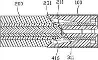
图5是图1电连接器及对接连接器组装后沿A-A线之剖视图。Fig. 5 is a cross-sectional view along line A-A after the electrical connector and the mating connector of Fig. 1 are assembled.
图6是图1电连接器及对接连接器组装后沿B-B线之剖视图。Fig. 6 is a cross-sectional view along line B-B after the electrical connector and the mating connector of Fig. 1 are assembled.
图7是图6电连接器及对接连接器组装后开始受力断开的剖视图。FIG. 7 is a cross-sectional view of the electrical connector and the mating connector in FIG. 6 beginning to be disconnected under force after being assembled.
图8是图7完全断开的剖视图。FIG. 8 is a fully broken sectional view of FIG. 7 .
【具体实施方式】【Detailed ways】
请参图1和图2,本发明电连接器组合包括电连接器100及可与该电连接器100相对接的对接连接器200。电连接器组合可以为电源连接器的插座和插头等。Please refer to FIG. 1 and FIG. 2 , the electrical connector assembly of the present invention includes an
请参图3及图4,电连接器100包括绝缘本体1、导电端子、固持件5及遮覆于绝缘本体外的遮蔽壳体6。Referring to FIG. 3 and FIG. 4 , the
所述绝缘本体1大致呈长方体状,其设有前端面10、与前端面10相对的后端面11、顶壁12、与顶壁12相对的底壁13及连接顶壁12和底壁13的左右侧壁14。为方便描述,在此定义前端面10所在侧为前侧而后端面11所在侧为后侧。所述绝缘本体1内部形成贯穿后端面11和顶壁12并大致呈U型的收容腔15。所述收容腔15靠近前端面10处左右距离较宽,并逐步向后端面11收拢变窄,又在靠近后端面11处突然变宽(请参图6)。所述前端面10为对接面,并在前端面10上开设有与收容腔15相连通的开口101。该开口101呈喇叭状,其包括设置于内部靠近收容腔15且呈圆柱状的内开口1011和设置于外部且呈圆锥状的外开口1012。所述底壁13向收容腔15凸设一呈岛屿状的配合部16。所述配合部16从底壁13一体延伸并设有前面161、后面162、顶面163和左右侧面164。所述前面161与前端面11间隔一段距离,所述前端面11与前面161之间形成可收容对接连接器200的对接腔151,所述开口101为对接腔151在前端面11上形成。所述侧面164与侧壁14亦间隔一段距离形成侧向空间152。所述后面162与后端面11平齐,并由后面162向内凹设形成贯穿前面161的第一收容槽171。所述顶面163低于顶壁12的表面,该表面163的后侧继续下陷与侧向空间形成固定部172,该固持部172的两侧设有贯穿底壁13的插孔1721。所述顶面163的前侧竖直凹陷有第二收容槽173,该第二收容槽173包括两侧并排设置的槽体。所述侧壁14的外壁面上设置有从顶壁12向下延伸的导引槽141和从底壁13向上延伸的限位槽142,并且导引槽141和限位槽142之间设有限位部143。The insulating body 1 is roughly in the shape of a cuboid, and it is provided with a
请参图1至图4,电连接器100的导电端子包括第一端子3、第二端子4及扣持件5。第一端子3可以充当正极端子并从后向前组装收容于第一收容槽171内,该第一端子3包括与第一收容槽171相固持的第一固持部30、自第一固持部30一端向前弯折并倾斜延伸的第一弹性接触臂31及自第一固持部30另一端弯折后向下延伸的第一焊接部32。所述第一弹性接触臂31的末端弯折并于弯折处形成延伸入对接腔151的弹性的第一接触部311。Referring to FIGS. 1 to 4 , the conductive terminals of the
第二端子4可以充当接地端子及负极端子,该第二端子4包括呈马鞍状且跨设于固定部172上的第二固持部40、自第二固持部40两边分别于侧向空间152向前延伸直至进入对接腔151内的一对第二弹性接触臂41及自第二固持部40两边分别向下延伸并可插入插孔1721的第二焊接部42。所述第二弹性接触臂41系挟持臂且其前端形成一挟持部411,挟持部411上开设有呈矩形状的固持口412,固持口412包括前边413、上边414和下边415。上边414和下边415于固持口412内侧被倒圆呈弧状,而前边413则整体被倒圆而呈柱状,并在前边413的内侧形成位于第一接触部311两侧的第二接触部416。The second terminal 4 can serve as a ground terminal and a negative terminal. The second terminal 4 includes a
扣持件5为定位端子且收容于第二收容槽173内。该扣持件5包括拥有可分别组装入第二收容槽173内的固持脚501的第三固持部50及自第三固持部50向前延伸的第三弹性接触臂51。第三弹性接触臂51的末端向下弯折后再向后弯折并在端部形成延伸入对接腔151内的扣持部511。The
遮蔽壳体6由金属板制成且大致呈门型状,其包括遮覆于顶壁12的上片60、遮覆于侧壁14的侧片61及自侧片向下延伸出的焊接脚62。所述上片60的前边缘向前凸设有与相应设置于上壁12上的定位部121相配合的定位槽601。所述侧片61上开设有若干限位片611。遮蔽壳体6从上向下组装于绝缘本体1时,所述限位片611滑过侧壁14之导引槽141后进入限位槽142内并与限位块143相互配合。The shielding shell 6 is made of metal plate and is roughly in the shape of a door. It includes an upper piece 60 covering the top wall 12, a side piece 61 covering the
请参图1、图2和图5,本发明对接连接器200一般为线缆连接器,图示只显示与电连接器100相配合的对接部分。所述对接连接器200为呈轴对称之圆形柱状结构,由里向外分别为第三端子21、绝缘的第一本体22、第四端子23及绝缘的第二本体24。第三端子21位于中心位置处呈圆柱状。第一本体22内中空且收容第三端子21并呈具有头部221的螺钉状,所述头部221上设有凹槽222,第三端子21的端面与凹槽221的底面相平齐,该端面形成第三接触部211。第四端子23呈管状套设于第一本体22外且与头部221相抵,并于靠近头部221处向内凹陷形成弧状的第四接触部231。头部221与第三端子21的交界处形成导引部223。第二本体24也呈管状并套设于第四端子23的外面。第二本体24往后缩一段距离,其最前端位于第四接触部231的后侧,第二本体24在前端处形成圆锥状的固定部241及环状的抵接部242。所述对接连接器200在抵接部242开始至前端形成插入对接腔151的对接部25。Please refer to FIG. 1 , FIG. 2 and FIG. 5 , the
请参图5和图6,对接连接器200与电连接器100相对接,对接部25插入对接腔151内,导引部223先与第二接触部416相接触并导引第二接触部416滑入第四接触部231内并与之相配合。当头部221抵触于前面161时对接部25完全插入,第三接触部211抵触第一接触部32使第一接触臂32弹性变形,扣持部511扣持于导引部223上,并且固定部241收容于外开口1012内并与外开口对应配合,抵接部242抵靠于前端面10。第二弹性接触臂41之间的距离小于第四接触部231的直径,使第二接触部416弹性抵触并扣持第四接触部231,使对接部25挟持于第二弹性接触臂416之间;固定部241与外开口112的相互配合,如此,电连接器与对接连接器实现相互配合。另,特设置扣持件5,通过扣持部511扣持对接部25上以防止对接连接器200因自重断开及加强固持。Please refer to FIG. 5 and FIG. 6 , the
请参图7和图8,将电连接器100与对接连接器200断开时,仅需对对接连接器200施加一异于对接方向的侧向力,本发明实施方式中为垂直于对接方向的力F,抵接部242外侧边缘抵触于前端面上并以接触点为支撑点A开始向下旋转,对接部25作用于第二弹性接触臂41并使第二弹性接触臂41向两边弹性变形并逐渐脱离第四接触部231,继续向外旋转,因支撑点A至对接部25最大距离(如支撑点A至B点的距离)小于支撑点A至内开口1011壁的最小距离(如支撑点A至C点的距离)使对接部25顺利旋转出对接腔251,从而实现快速脱离。7 and 8, when disconnecting the
本发明电连接器之设有相对前端面缩进的配合部且配合部的前面与前端面之间形成对接腔,前端面与对接面之间的距离小于圆形开口的直径,使电连接器具有足够大的口径使对接部藉支撑点直接转出以实现快速脱离。电连接器的端子均为可动端子,对接连接器的端子均为固定端子,第二端子之挟持臂可于收容腔内弹性变形,这些均为帮助电连接器和对接连接器实现快速脱离。The electrical connector of the present invention is provided with a mating portion indented relative to the front end face, and a docking cavity is formed between the front face of the mating portion and the front end face, and the distance between the front end face and the butt face is smaller than the diameter of the circular opening, so that the electrical connector With a large enough diameter, the docking part can be directly rotated out by the support point to achieve quick disengagement. The terminals of the electrical connector are all movable terminals, the terminals of the docking connector are all fixed terminals, and the holding arm of the second terminal can be elastically deformed in the receiving cavity, all of which help the electrical connector and the docking connector to realize quick disengagement.
Claims (10)
Priority Applications (1)
| Application Number | Priority Date | Filing Date | Title |
|---|---|---|---|
| CN 200910312328CN102110944B (en) | 2009-12-26 | 2009-12-26 | Electric connector and combination thereof |
Applications Claiming Priority (1)
| Application Number | Priority Date | Filing Date | Title |
|---|---|---|---|
| CN 200910312328CN102110944B (en) | 2009-12-26 | 2009-12-26 | Electric connector and combination thereof |
Publications (2)
| Publication Number | Publication Date |
|---|---|
| CN102110944A CN102110944A (en) | 2011-06-29 |
| CN102110944Btrue CN102110944B (en) | 2013-04-03 |
Family
ID=44175012
Family Applications (1)
| Application Number | Title | Priority Date | Filing Date |
|---|---|---|---|
| CN 200910312328ActiveCN102110944B (en) | 2009-12-26 | 2009-12-26 | Electric connector and combination thereof |
Country Status (1)
| Country | Link |
|---|---|
| CN (1) | CN102110944B (en) |
Families Citing this family (2)
| Publication number | Priority date | Publication date | Assignee | Title |
|---|---|---|---|---|
| CN105024222A (en)* | 2015-07-19 | 2015-11-04 | 盛明星 | Elastic clamping buckle electrical connection method and device |
| CN113285265B (en)* | 2020-02-19 | 2023-06-16 | 上海莫仕连接器有限公司 | Electric connector and electric connector combination |
Citations (3)
| Publication number | Priority date | Publication date | Assignee | Title |
|---|---|---|---|---|
| DE19816695A1 (en)* | 1997-04-16 | 1998-10-22 | Hosiden Corp | Voltage supply socket |
| US6382999B1 (en)* | 2000-09-29 | 2002-05-07 | Hon Hai Precision Ind. Co., Ltd. | Anti-spark power jack |
| CN2545728Y (en)* | 2001-09-20 | 2003-04-16 | 广东德豪润达电器股份有限公司 | Cordless electric connector |
- 2009
- 2009-12-26CNCN 200910312328patent/CN102110944B/enactiveActive
Patent Citations (3)
| Publication number | Priority date | Publication date | Assignee | Title |
|---|---|---|---|---|
| DE19816695A1 (en)* | 1997-04-16 | 1998-10-22 | Hosiden Corp | Voltage supply socket |
| US6382999B1 (en)* | 2000-09-29 | 2002-05-07 | Hon Hai Precision Ind. Co., Ltd. | Anti-spark power jack |
| CN2545728Y (en)* | 2001-09-20 | 2003-04-16 | 广东德豪润达电器股份有限公司 | Cordless electric connector |
Non-Patent Citations (1)
| Title |
|---|
| JP特开2007-95349A 2007.04.12 |
Also Published As
| Publication number | Publication date |
|---|---|
| CN102110944A (en) | 2011-06-29 |
Similar Documents
| Publication | Publication Date | Title |
|---|---|---|
| US10205256B2 (en) | Plug and electrical connector component | |
| TWI459653B (en) | Coaxial electric connector | |
| CN102842809B (en) | Cable Connector Assembly | |
| US8123544B2 (en) | Electrical connector assembly adapted to withstand rotational movement | |
| TWI412186B (en) | Electrical connector and electrical connector assembly | |
| US10177477B2 (en) | Connector and connector assembly | |
| CN105591235A (en) | Plug connector and electronic equipment with same | |
| CN201436736U (en) | audio socket connector | |
| CN202196895U (en) | Electric connector and electric connector assembly | |
| CN106887726B (en) | Clamping devices, electrical connectors and connector assemblies | |
| CN102110944B (en) | Electric connector and combination thereof | |
| CN203660203U (en) | Switch electric connector | |
| CN201112877Y (en) | electrical connector | |
| TWI827859B (en) | Electrical connector assembly | |
| CN201430325Y (en) | Socket connector and its mating plug connector | |
| CN201075427Y (en) | Electric Connector | |
| CN101771209B (en) | Socket contact | |
| CN115693283A (en) | Connector plug, its docking structure and electrical connection wire | |
| CN102842813B (en) | Electric connector and butting connector | |
| CN201285939Y (en) | Electric connector | |
| CN102280765B (en) | Connector | |
| JP2010073353A (en) | Interface connector and plug | |
| CN201142405Y (en) | electrical connector | |
| CN108631118B (en) | Electric connector combination | |
| CN110808506B (en) | Coaxial connector |
Legal Events
| Date | Code | Title | Description |
|---|---|---|---|
| C06 | Publication | ||
| PB01 | Publication | ||
| C10 | Entry into substantive examination | ||
| SE01 | Entry into force of request for substantive examination | ||
| C14 | Grant of patent or utility model | ||
| GR01 | Patent grant |