CN102106766A - Novel linear driving device - Google Patents
Novel linear driving deviceDownload PDFInfo
- Publication number
- CN102106766A CN102106766ACN2011100505411ACN201110050541ACN102106766ACN 102106766 ACN102106766 ACN 102106766ACN 2011100505411 ACN2011100505411 ACN 2011100505411ACN 201110050541 ACN201110050541 ACN 201110050541ACN 102106766 ACN102106766 ACN 102106766A
- Authority
- CN
- China
- Prior art keywords
- motor
- push rod
- guide pin
- fixed
- pin bushing
- Prior art date
- Legal status (The legal status is an assumption and is not a legal conclusion. Google has not performed a legal analysis and makes no representation as to the accuracy of the status listed.)
- Granted
Links
Images


Landscapes
- Transmission Devices (AREA)
Abstract
Translated fromChineseDescription
Translated fromChinese技术领域technical field
本发明涉及一种新型的线性驱动装置,尤其是涉及一种应用于外骨骼机械腿的线性驱动装置。The invention relates to a novel linear driving device, in particular to a linear driving device applied to an exoskeleton mechanical leg.
the
背景技术Background technique
在现代的社会生产生活中,随着交通运输工具的迅速增长和人口老龄化程度的不断加深,受神经损伤或者肢体损伤的人数也越来越多,老年人群和残疾人士的护理将成为社会的一个重要负担,因此,设计与研发适宜于老年人使用的外骨骼机械腿具显得尤为重要,用来帮助老年人或残疾人行走,完成跨步,上下台阶等任务,满足他们的生活所需。In modern social production and life, with the rapid growth of means of transportation and the deepening of the aging population, more and more people are injured by nerves or limbs. Nursing care for the elderly and the disabled will become a social priority. Therefore, it is particularly important to design and develop exoskeleton mechanical legs suitable for the elderly, which are used to help the elderly or disabled to walk, complete tasks such as strides, and up and down steps to meet their daily needs.
目前大部分机械腿主要采用旋转驱动器或普通的旋转电机加丝杠螺母形式的线性驱动装置。由于电机转速过快,旋转驱动系统需要配置一个减速器,减速大,减速器的尺寸往往也会很大,这会导致关节处机构过于庞大。同时,安装在机械腿外侧的驱动器会导致重心向外偏移,影响患者的正常行走。线性驱动系统利用各种能产生直线位移的驱动器来模拟相应关节处屈肌和伸肌所产生的屈伸运动,从而实现关节转动,符合仿生学拟人化的原则。大多数的线性驱动器通常采用普通旋转电机加丝杠螺母的形式,此类驱动器整体尺寸大、结构复杂,摩擦阻力大,驱动效果不是十分理想。At present, most of the mechanical legs mainly adopt a linear drive device in the form of a rotary drive or a common rotary motor plus a screw nut. Due to the high speed of the motor, the rotary drive system needs to be equipped with a reducer. If the reduction is large, the size of the reducer will often be large, which will cause the joint mechanism to be too large. At the same time, the driver installed on the outside of the mechanical leg will cause the center of gravity to shift outward, affecting the normal walking of the patient. The linear drive system uses various drivers that can generate linear displacement to simulate the flexion and extension movements generated by the flexor and extensor muscles at the corresponding joints, so as to realize joint rotation, which is in line with the anthropomorphic principle of bionics. Most of the linear actuators are usually in the form of ordinary rotary motors plus screw nuts. This type of actuator has a large overall size, complex structure, high frictional resistance, and the driving effect is not very ideal.
the
发明内容Contents of the invention
本发明的目的在于克服现有机械腿驱动技术存在的上述问题,提供一种新型的线性驱动装置,具有结构简单紧凑,同轴性好,行程大,阻力小,传动误差小,控制容易等特点。The purpose of the present invention is to overcome the above-mentioned problems existing in the existing mechanical leg drive technology, and provide a new type of linear drive device, which has the characteristics of simple and compact structure, good coaxiality, large stroke, small resistance, small transmission error, and easy control. .
为达到上述目的,本发明的构思是:In order to achieve the above-mentioned purpose, design of the present invention is:
本新型线性驱动装置,包括驱动部分、传动部分、导向部分、安装定位部分和连接部分;所述的驱动部分采用特种步进电机,电机和丝杆螺母做成一个整体,使整个驱动装置的机构更加紧凑,丝杆螺母把电机的旋转运动转换为直线运动;The novel linear driving device includes a driving part, a transmission part, a guiding part, an installation positioning part and a connecting part; the driving part adopts a special stepping motor, and the motor and the screw nut are made into a whole, so that the mechanism of the whole driving device More compact, the screw nut converts the rotary motion of the motor into linear motion;
所述的传动部分采用空心式的推杆,其内穿过丝杆,内端与丝杆螺母固定连接,外端固定在连接耳上,推杆内孔和丝杆螺母外圆柱面采用基轴制配合,保证驱动装置具有良好的同轴性;所述的导向部分主要包括柱形导套、法兰式导套和外套筒,是整个驱动装置中较为关键的一个环节,柱形导套安装在内推杆内端上,其内孔与内推杆采用基孔制配合,外圆柱面与外套筒内孔采用基轴制配合,在保证驱动器行程足够的前提下,加大柱形导套的长度,使其具有较好的支撑作用,法兰式导套采用两半对合式结构,一方面便于加工,另一方面便于安装及位置调整,其内表面与内推杆采用基孔制配合,外圆柱面与外套筒内孔采用基轴制配合,利用法兰式结构固定在外套筒上;外套筒固定在电机箱上,并采用定位孔定位,使其具有良好的同轴度。导向部分不仅起到了良好的导向支撑作用,而且限制了内推杆的轴向转动,使其运动更加平稳,高精度的配合减少了摩擦阻力;所述的安装定位部分主要包括电机箱和电机箱后盖板,为了提高同轴度,电机箱内壁加工有定位孔,电机箱后盖板加工有矩形凸台,与电机箱内壁配合。所述的连接部分用于和外部的机械腿相连接,主要包括连接耳和连接耳座,分别与内推杆和电机箱后盖板相连,同样采用定位孔定位,提高同轴度。The transmission part adopts a hollow push rod, which passes through the screw rod, the inner end is fixedly connected with the screw nut, and the outer end is fixed on the connecting ear. The inner hole of the push rod and the outer cylindrical surface of the screw nut adopt the base shaft system fit to ensure that the drive device has good coaxiality; the guide part mainly includes a cylindrical guide sleeve, a flanged guide sleeve and an outer sleeve, which is a key link in the entire drive device. The cylindrical guide sleeve Installed on the inner end of the inner push rod, the inner hole and the inner push rod adopt the base hole system, and the outer cylindrical surface and the inner hole of the outer sleeve adopt the base shaft system. On the premise of ensuring that the stroke of the driver is sufficient, the cylindrical shape is enlarged. The length of the guide sleeve makes it have a good supporting effect. The flange type guide sleeve adopts a two-half combined structure, which is convenient for processing on the one hand, and convenient for installation and position adjustment on the other hand. The inner surface and the inner push rod adopt the base hole The outer cylindrical surface and the inner hole of the outer sleeve adopt the base shaft system, and are fixed on the outer sleeve by a flange structure; the outer sleeve is fixed on the motor box, and is positioned by positioning holes, so that it has good synchronous axis. The guide part not only plays a good guiding and supporting role, but also limits the axial rotation of the inner push rod, making its movement more stable, and the high-precision fit reduces frictional resistance; the installation and positioning part mainly includes the motor box and the motor box For the rear cover, in order to improve the coaxiality, the inner wall of the motor box is processed with positioning holes, and the rear cover of the motor box is processed with a rectangular boss to match the inner wall of the motor box. The connecting part is used to connect with the external mechanical legs, and mainly includes connecting lugs and connecting lug seats, which are respectively connected with the inner push rod and the rear cover of the motor box. Positioning holes are also used for positioning to improve coaxiality.
根据上述发明构思,本发明采用下述技术方案:According to above-mentioned inventive concept, the present invention adopts following technical scheme:
一种新型的线性驱动装置,其特征在于将一个特种步进电机安装在一个电机箱内;一根内推杆采用空心式结构,其内穿过一根丝杆,内端与一个丝杆螺母固定相连,外端固定在一个连接耳上;一个柱形导套固定在所述内推杆内端上,其外圆柱面与一个外套筒的内孔相滑配;该外套筒呈工字型结构,一端固定连接在所述电机箱上,另一端固定连接一个法兰式导套;该法兰式导套内孔与所述内推杆轴向滑动配合,而外圆柱面与所述外套筒的内孔相配合;一个连接耳座固定在一个电机箱后盖板上;该电机箱后盖板固定在所述电机箱上,其内表面加工有矩形凸台,与电机箱内壁相配合。A new type of linear drive device is characterized in that a special stepping motor is installed in a motor box; an inner push rod adopts a hollow structure, and a screw rod passes through it, and the inner end is connected with a screw nut Fixedly connected, the outer end is fixed on a connecting ear; a cylindrical guide sleeve is fixed on the inner end of the inner push rod, and its outer cylindrical surface is slidingly matched with the inner hole of an outer sleeve; the outer sleeve is a working font structure, one end is fixedly connected to the motor box, and the other end is fixedly connected to a flanged guide bush; the inner hole of the flanged guide bush is axially fitted with the inner push rod, and the outer cylindrical surface is fitted The inner hole of the outer sleeve is matched; a connecting lug is fixed on the back cover of a motor box; Compatible with the inner wall.
上述特种步进电机,是将电机与丝杆和丝杆螺母做成一个整体;所述法兰式导套内孔与内推杆轴向滑动配合的结构是:内推杆的外圆柱面上铣有两个相互平行的平面,与法兰式导套的内孔相配合,法兰式导套采用两半对合式结构,固定在外套筒上。The above-mentioned special stepping motor is made of the motor, the screw and the screw nut as a whole; the structure of the inner hole of the flange guide sleeve and the axial sliding cooperation of the inner push rod is: the outer cylindrical surface of the inner push rod Milling has two parallel planes, which match the inner hole of the flanged guide bush, and the flanged guide bush adopts a two-half mating structure, which is fixed on the outer sleeve.
the
本发明与现有技术相比较,具有如下显而易见的实质性特点和显著优点:采用特种步进电机,使驱动装置的整体结构更加紧凑,增大了线性驱动系统的行程,同时也有效的解决了驱动装置与机械腿关节容易发生干涉的问题;导套的使用使得驱动系统的输出更加平稳,解决了推杆容易发生轴向转动的问题,高精度的配合减少了驱动装置的内部摩擦阻力;本发明装配时采用了较多配合和定位孔定位,使整个驱动装置具有很高的同轴度,解决了以往因同轴度过低而导致摩擦阻力过大的问题,减少了传动误差,使其输出更加精确,更容易控制。Compared with the prior art, the present invention has the following obvious substantive features and significant advantages: the use of special stepping motors makes the overall structure of the drive device more compact, increases the stroke of the linear drive system, and effectively solves the problem of The problem of easy interference between the drive device and the mechanical leg joint; the use of the guide sleeve makes the output of the drive system more stable, which solves the problem that the push rod is prone to axial rotation, and the high-precision cooperation reduces the internal friction resistance of the drive device; The invention adopts more coordination and positioning holes for positioning during assembly, so that the entire driving device has a high degree of coaxiality, which solves the problem of excessive frictional resistance caused by too low coaxiality in the past, reduces transmission errors, and makes it The output is more precise and easier to control.
the
附图说明Description of drawings
图1为本发明新型的线性驱动装置三维示意图。Figure 1 is a three-dimensional schematic diagram of the new linear drive device of the present invention.
图2为本发明新型的线性驱动装置结构爆炸图。Figure 2 is an exploded view of the structure of the new linear drive device of the present invention.
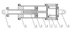
图3为本发明新型的线性驱动装置总装配图。Fig. 3 is a general assembly diagram of the novel linear drive device of the present invention.
the
具体实施方式Detailed ways
本发明的优选实施例结合附图说明如下:Preferred embodiments of the present invention are described as follows in conjunction with the accompanying drawings:
参见图1、图2和图3,本新型线性驱动装置包括特种步进电机(1)、内推杆(2)、柱形导套(3)、外套筒(4)、法兰式导套(5)、连接耳(6)、电机箱(7)、电机箱后盖板(8)和连接耳座(9)。特种步进电机(1)的最大特点是把电机和丝杆螺母做成一个整体,使得驱动装置的结构变得更加紧凑;电机固定在电机箱(7)内,电机箱内壁加工有定位孔,使驱动装置具有良好的同轴性;内推杆(2)采用空心式结构,穿过丝杆固定在丝杆螺母上,内推杆(2)的外圆柱面上铣有两个相互平行的平面,与法兰式导套(5)的内孔相配合,法兰式导套(5)采用两半对合式结构,外圆柱面与外套筒(4)的内孔相配合,法兰式导套(5)一方面起到比较好的导向支撑作用,另一方面限制了内推杆的轴向转动;柱形导套(3)固定在内推杆(2)的一端,其内孔与内推杆(2)端面上的外圆柱面相配合,外圆柱面和外套筒(4)的内孔相配合,在保证驱动器行程足够的前提下,加大柱形导套的长度;外套筒(4)固定在电机箱(7)上,采用定位孔定位,电机箱后盖板(8)加工有矩形凸台,与电机箱(7)内壁配合,采取这种装配方式,提高了驱动器的同轴性;连接耳(6)和连接耳座(9)分别固定在内推杆(2)和电机箱后盖板(8)上,用于连接外部的机械腿。Referring to Fig. 1, Fig. 2 and Fig. 3, the new linear drive device includes a special stepping motor (1), an inner push rod (2), a cylindrical guide sleeve (3), an outer sleeve (4), a flanged guide Set (5), connecting ear (6), motor box (7), motor box rear cover (8) and connecting ear seat (9). The biggest feature of the special stepping motor (1) is that the motor and the screw nut are integrated to make the structure of the driving device more compact; the motor is fixed in the motor box (7), and the inner wall of the motor box is processed with positioning holes. Make the driving device have good coaxiality; the inner push rod (2) adopts a hollow structure, passes through the screw rod and is fixed on the screw nut, and the outer cylindrical surface of the inner push rod (2) is milled with two parallel Flat surface, matched with the inner hole of the flanged guide bush (5), the flanged guide bush (5) adopts a two-half mating structure, the outer cylindrical surface matches the inner hole of the outer sleeve (4), and the flange The cylindrical guide sleeve (5) plays a better guiding and supporting role on the one hand, and limits the axial rotation of the inner push rod on the other hand; the cylindrical guide sleeve (3) is fixed at one end of the inner push rod (2), and the inner push rod (2) The hole is matched with the outer cylindrical surface on the end surface of the inner push rod (2), and the outer cylindrical surface is matched with the inner hole of the outer sleeve (4). On the premise of ensuring sufficient stroke of the driver, the length of the cylindrical guide sleeve is increased; The outer sleeve (4) is fixed on the motor box (7) and is positioned by positioning holes. The rear cover plate (8) of the motor box is processed with a rectangular boss to match the inner wall of the motor box (7). This assembly method improves the The coaxiality of the driver is ensured; the connecting ear (6) and the connecting ear seat (9) are respectively fixed on the inner push rod (2) and the rear cover plate (8) of the motor box, and are used to connect the external mechanical legs.
工作时,发送脉冲控制步进电机(1)转动,丝杠螺母把电机的旋转运动转换为内推杆(2)的直线运动,实现驱动装置的伸长与缩短。柱形导套(3)和法兰式导套(5)起导向支撑作用,使内推杆(2)在整个运动过程变得更加平稳,并防止了内推杆(2)的轴向转动。When working, send pulses to control the rotation of the stepping motor (1), and the screw nut converts the rotational motion of the motor into the linear motion of the inner push rod (2), so as to realize the elongation and shortening of the driving device. The cylindrical guide sleeve (3) and the flanged guide sleeve (5) act as a guide and support, making the inner push rod (2) more stable during the whole movement process and preventing the axial rotation of the inner push rod (2) .
本发明建立了一种新型的线性驱动装置,结构简单紧凑,同轴性好,行程大,阻力小,传动误差小,控制容易。The invention establishes a new type of linear drive device, which has simple and compact structure, good coaxiality, large stroke, small resistance, small transmission error and easy control.
Claims (2)
Priority Applications (1)
| Application Number | Priority Date | Filing Date | Title |
|---|---|---|---|
| CN 201110050541CN102106766B (en) | 2011-03-03 | 2011-03-03 | Novel linear driving device |
Applications Claiming Priority (1)
| Application Number | Priority Date | Filing Date | Title |
|---|---|---|---|
| CN 201110050541CN102106766B (en) | 2011-03-03 | 2011-03-03 | Novel linear driving device |
Publications (2)
| Publication Number | Publication Date |
|---|---|
| CN102106766Atrue CN102106766A (en) | 2011-06-29 |
| CN102106766B CN102106766B (en) | 2013-04-03 |
Family
ID=44171134
Family Applications (1)
| Application Number | Title | Priority Date | Filing Date |
|---|---|---|---|
| CN 201110050541Expired - Fee RelatedCN102106766B (en) | 2011-03-03 | 2011-03-03 | Novel linear driving device |
Country Status (1)
| Country | Link |
|---|---|
| CN (1) | CN102106766B (en) |
Cited By (12)
| Publication number | Priority date | Publication date | Assignee | Title |
|---|---|---|---|---|
| CN102518757A (en)* | 2011-12-14 | 2012-06-27 | 河南科技大学 | A robot vehicle transmission device |
| CN102785721A (en)* | 2012-07-11 | 2012-11-21 | 上海大学 | Pedal type gait robot |
| CN103878790A (en)* | 2014-04-18 | 2014-06-25 | 南京工程学院 | Multi-mode elastic driver for lower limb power-assisted exoskeleton robot |
| CN105662663A (en)* | 2016-03-18 | 2016-06-15 | 王威 | Implant capable of automatically extending |
| CN103378707B (en)* | 2012-04-23 | 2017-12-19 | 德昌电机(深圳)有限公司 | Motor, Linear actuator and the car lamp adjuster using the Linear actuator |
| CN109019190A (en)* | 2018-08-17 | 2018-12-18 | 上海宇航系统工程研究所 | Random rope withdrawing apparatus |
| CN109484917A (en)* | 2018-11-15 | 2019-03-19 | 上海宇航系统工程研究所 | A kind of random rope withdrawing apparatus |
| CN110024752A (en)* | 2019-05-22 | 2019-07-19 | 吉林大学 | A kind of fixture for insect leg joint friction test |
| CN110641576A (en)* | 2019-10-17 | 2020-01-03 | 博众精工科技股份有限公司 | A steering wheel AGV mobile platform |
| CN111608406A (en)* | 2020-06-04 | 2020-09-01 | 山东弘宜装配式建筑科技有限公司 | Adjustable support rod for prefabricated building and operation method thereof |
| CN111728746A (en)* | 2020-06-08 | 2020-10-02 | 清华大学 | A device for simulating the movement of the deep muscles of the residual limb |
| CN116793141A (en)* | 2023-06-20 | 2023-09-22 | 重庆建设工业(集团)有限责任公司 | Fault bomb removing device for satellite-borne weapon |
Citations (7)
| Publication number | Priority date | Publication date | Assignee | Title |
|---|---|---|---|---|
| US5020790A (en)* | 1990-10-23 | 1991-06-04 | Board Of Supervisors Of Louisiana State University And Agricultural And Mechanical College | Powered gait orthosis |
| JP2000056050A (en)* | 1998-08-11 | 2000-02-25 | Ntn Corp | Linear driving device and positioning unit using it |
| JP2006043871A (en)* | 2004-06-28 | 2006-02-16 | Rikogaku Shinkokai | Walking device |
| CN1965169A (en)* | 2004-10-08 | 2007-05-16 | 施塔比鲁斯有限责任公司 | Linear drive |
| CN101496751A (en)* | 2009-03-11 | 2009-08-05 | 河北工业大学 | Active mode human leg prosthetic limb |
| CN201355323Y (en)* | 2009-02-27 | 2009-12-02 | 大连齐维科技发展有限公司 | Ultrahigh vacuum linear pushing importer |
| CN201356682Y (en)* | 2009-03-11 | 2009-12-09 | 河北工业大学 | Powered artificial human leg |
- 2011
- 2011-03-03CNCN 201110050541patent/CN102106766B/ennot_activeExpired - Fee Related
Patent Citations (7)
| Publication number | Priority date | Publication date | Assignee | Title |
|---|---|---|---|---|
| US5020790A (en)* | 1990-10-23 | 1991-06-04 | Board Of Supervisors Of Louisiana State University And Agricultural And Mechanical College | Powered gait orthosis |
| JP2000056050A (en)* | 1998-08-11 | 2000-02-25 | Ntn Corp | Linear driving device and positioning unit using it |
| JP2006043871A (en)* | 2004-06-28 | 2006-02-16 | Rikogaku Shinkokai | Walking device |
| CN1965169A (en)* | 2004-10-08 | 2007-05-16 | 施塔比鲁斯有限责任公司 | Linear drive |
| CN201355323Y (en)* | 2009-02-27 | 2009-12-02 | 大连齐维科技发展有限公司 | Ultrahigh vacuum linear pushing importer |
| CN101496751A (en)* | 2009-03-11 | 2009-08-05 | 河北工业大学 | Active mode human leg prosthetic limb |
| CN201356682Y (en)* | 2009-03-11 | 2009-12-09 | 河北工业大学 | Powered artificial human leg |
Cited By (14)
| Publication number | Priority date | Publication date | Assignee | Title |
|---|---|---|---|---|
| CN102518757A (en)* | 2011-12-14 | 2012-06-27 | 河南科技大学 | A robot vehicle transmission device |
| CN103378707B (en)* | 2012-04-23 | 2017-12-19 | 德昌电机(深圳)有限公司 | Motor, Linear actuator and the car lamp adjuster using the Linear actuator |
| CN102785721A (en)* | 2012-07-11 | 2012-11-21 | 上海大学 | Pedal type gait robot |
| CN103878790A (en)* | 2014-04-18 | 2014-06-25 | 南京工程学院 | Multi-mode elastic driver for lower limb power-assisted exoskeleton robot |
| CN103878790B (en)* | 2014-04-18 | 2015-08-12 | 南京工程学院 | Towards the multi-mode elastic driver of lower limb assistance exoskeleton robot |
| CN105662663A (en)* | 2016-03-18 | 2016-06-15 | 王威 | Implant capable of automatically extending |
| CN109019190A (en)* | 2018-08-17 | 2018-12-18 | 上海宇航系统工程研究所 | Random rope withdrawing apparatus |
| CN109484917A (en)* | 2018-11-15 | 2019-03-19 | 上海宇航系统工程研究所 | A kind of random rope withdrawing apparatus |
| CN110024752A (en)* | 2019-05-22 | 2019-07-19 | 吉林大学 | A kind of fixture for insect leg joint friction test |
| CN110024752B (en)* | 2019-05-22 | 2023-10-24 | 吉林大学 | Clamp for insect leg joint friction test |
| CN110641576A (en)* | 2019-10-17 | 2020-01-03 | 博众精工科技股份有限公司 | A steering wheel AGV mobile platform |
| CN111608406A (en)* | 2020-06-04 | 2020-09-01 | 山东弘宜装配式建筑科技有限公司 | Adjustable support rod for prefabricated building and operation method thereof |
| CN111728746A (en)* | 2020-06-08 | 2020-10-02 | 清华大学 | A device for simulating the movement of the deep muscles of the residual limb |
| CN116793141A (en)* | 2023-06-20 | 2023-09-22 | 重庆建设工业(集团)有限责任公司 | Fault bomb removing device for satellite-borne weapon |
Also Published As
| Publication number | Publication date |
|---|---|
| CN102106766B (en) | 2013-04-03 |
Similar Documents
| Publication | Publication Date | Title |
|---|---|---|
| CN102106766A (en) | Novel linear driving device | |
| CN106514701B (en) | A kind of flexible joint of stiffness variable | |
| CN104825312B (en) | A kind of exoskeleton robot shank self adaptation bondage device | |
| CN102152319B (en) | Elastic Drive Rotary Joint | |
| CN102743838A (en) | Novel lower limb joint mechanism of reclining-type Lower limb rehabilitation robot | |
| CN107854277A (en) | Wrist joint rehabilitation training device | |
| CN103287522B (en) | A kind of based on hydraulically powered robot bouncing mechanism | |
| CN100382938C (en) | Pitching and turning integrated waist structure of humanoid robot | |
| CN206598286U (en) | A kind of motion of robot four-degree-of-freedom mechanical arm | |
| CN209535272U (en) | A kind of robot deformation leg with the sufficient ability to transform of wheel | |
| CN104890006B (en) | Compound Drive Bionic Elbow Joint | |
| CN215193448U (en) | A new type of wearable finger joint rehabilitation device | |
| CN106551777B (en) | A kind of brachium regulating device of upper limb exoskeleton rehabilitation robot | |
| CN206036160U (en) | Screw thread interstitial structure is eliminated to lead screw motor | |
| CN104772759B (en) | The flexible actuator of bionic muscle | |
| CN106956289A (en) | A kind of apery mechanical arm based under DC motor Driver | |
| CN111941413A (en) | Novel electromagnetic controllable flexible driving device and control method thereof | |
| CN113442167B (en) | Flexible variable-stiffness elastic driver and control method thereof | |
| CN206536503U (en) | A kind of rotary-type variation rigidity flexible joint | |
| CN210650683U (en) | Robot arm driving device and double-arm robot | |
| CN202908969U (en) | Mechanism with leg massage function and multifunctional wheel chair with the same | |
| CN211272057U (en) | An upper limb rehabilitation exoskeleton device based on gear and link transmission | |
| CN210137243U (en) | Stable push rod motor structure | |
| CN220358959U (en) | Electric control precise linear motion mechanism | |
| CN110625595B (en) | Active knee joint structure of human exoskeleton |
Legal Events
| Date | Code | Title | Description |
|---|---|---|---|
| C06 | Publication | ||
| PB01 | Publication | ||
| C10 | Entry into substantive examination | ||
| SE01 | Entry into force of request for substantive examination | ||
| C14 | Grant of patent or utility model | ||
| GR01 | Patent grant | ||
| CF01 | Termination of patent right due to non-payment of annual fee | Granted publication date:20130403 Termination date:20180303 | |
| CF01 | Termination of patent right due to non-payment of annual fee |