CN102098890A - Electronic equipment - Google Patents
Electronic equipmentDownload PDFInfo
- Publication number
- CN102098890A CN102098890ACN2011100310926ACN201110031092ACN102098890ACN 102098890 ACN102098890 ACN 102098890ACN 2011100310926 ACN2011100310926 ACN 2011100310926ACN 201110031092 ACN201110031092 ACN 201110031092ACN 102098890 ACN102098890 ACN 102098890A
- Authority
- CN
- China
- Prior art keywords
- slopes
- outer frame
- electronic device
- electronic equipment
- user
- Prior art date
- Legal status (The legal status is an assumption and is not a legal conclusion. Google has not performed a legal analysis and makes no representation as to the accuracy of the status listed.)
- Pending
Links
Images
Classifications
- G—PHYSICS
- G06—COMPUTING OR CALCULATING; COUNTING
- G06F—ELECTRIC DIGITAL DATA PROCESSING
- G06F1/00—Details not covered by groups G06F3/00 - G06F13/00 and G06F21/00
- G06F1/16—Constructional details or arrangements
- G06F1/1613—Constructional details or arrangements for portable computers
- G06F1/1626—Constructional details or arrangements for portable computers with a single-body enclosure integrating a flat display, e.g. Personal Digital Assistants [PDAs]
Landscapes
- Engineering & Computer Science (AREA)
- Theoretical Computer Science (AREA)
- Computer Hardware Design (AREA)
- Human Computer Interaction (AREA)
- Physics & Mathematics (AREA)
- General Engineering & Computer Science (AREA)
- General Physics & Mathematics (AREA)
- Coupling Device And Connection With Printed Circuit (AREA)
- Casings For Electric Apparatus (AREA)
- Details Of Connecting Devices For Male And Female Coupling (AREA)
- Telephone Set Structure (AREA)
- Shielding Devices Or Components To Electric Or Magnetic Fields (AREA)
Abstract
Description
Translated fromChinese技术领域technical field
本发明涉及一种电子设备。The invention relates to an electronic device.
背景技术Background technique
便携式移动电子设备被用户广泛使用,其具有体积轻薄、方便携带的特点,从而方便用户随身携带、随时使用。然而,目前市场上推出的一些便携式电子设备,一般其前盖的表面均是设计成平面,而由于其体积轻薄、小巧,用户手持电子设备时往往需要谨慎握持,避免手滑。因此,上述情况给用户在使用便携式电子设备时带来不便。Portable mobile electronic devices are widely used by users, and have the characteristics of being light and thin and easy to carry, so that users can carry them around and use them at any time. However, for some portable electronic devices currently on the market, the front cover is generally designed to be flat, and because of its light, thin and small size, users often need to hold the electronic device carefully to avoid slipping. Therefore, the above-mentioned situation brings inconvenience to the user when using the portable electronic device.
发明内容Contents of the invention
有鉴于此,有必要提供一种电子设备,方便用户握持、操作。In view of this, it is necessary to provide an electronic device that is convenient for users to hold and operate.
一种电子设备,该电子设备包括一外框及一装设于该外框内地显示屏。该外框两个相对的侧边相向倾斜而分别形成一斜坡,该两个斜坡分别与该显示屏表面形成一倾角,当用户按压该边框两个相对的侧边时,在该两个斜坡的表面分别产生一沿该斜坡表面向上的摩擦力,将该电子设备夹持在用户手中。An electronic device includes an outer frame and a display screen installed in the outer frame. The two opposite sides of the outer frame are inclined towards each other to form a slope respectively, and the two slopes respectively form an inclination angle with the surface of the display screen, when the user presses the two opposite sides of the frame, the two slopes The surfaces respectively generate a frictional force upward along the sloped surface to clamp the electronic device in the user's hand.
相对于现有技术,本发明提供的电子设备,通过在外框相对的两侧设置相向倾斜的斜坡,方便用户握持。Compared with the prior art, the electronic equipment provided by the present invention is convenient for users to hold by setting oppositely inclined slopes on opposite sides of the outer frame.
附图说明Description of drawings
图1为本发明的电子设备的示意图。FIG. 1 is a schematic diagram of an electronic device of the present invention.
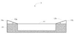
图2为本发明的电子设备沿II-II方向的剖面图。FIG. 2 is a cross-sectional view of the electronic device of the present invention along II-II direction.
主要元件符号说明Description of main component symbols
电子设备 1
外框 10
侧边 10a、10b
显示屏 11
斜坡 12a、12bSlopes 12a, 12b
具体实施方式Detailed ways
下面将结合附图,对本发明作进一步的详细说明。The present invention will be further described in detail below in conjunction with the accompanying drawings.
请参阅图1,为本发明的电子设备的示意图。本发明的电子设备1包括一外框10及一装设于该外框10内的显示屏11。Please refer to FIG. 1 , which is a schematic diagram of the electronic device of the present invention. The
请参阅图2,该外框10两个相对的侧边10a和10b相向倾斜形成斜坡12a和12b,该斜坡12a和12b均与显示屏11的表面形成一倾角θ。在本实施方式中,该倾角θ为1度,在其他实施方式中,该倾角还可设置为1~3度的任意数值,该倾角根据需要还可设置为其他数值。该斜坡12a和12b的表面设有凸起的花纹,用于当用户按压该斜坡12a和12b的表面时分别产生一沿斜坡表面向上的摩擦力f。Please refer to FIG. 2 , two
当用户握住该电子设备1时,手指按压侧边10a和10b,在该斜坡12a和12b的表面分别产生一沿斜坡表面向上的摩擦力f,这样,该产生在外框10两个相对的侧边的摩擦力与用户手指相互作用,将该电子设备1夹持在用户手中。When the user holds the
一般地,当用户握住外框设计成平面的电子设备时,由于手指与外框表面无相对运动趋势而不会产生摩擦力,因此用户需要用较大的压力夹持住电子设备。而当用户使用具有斜坡12a和12b的电子设备1,用户只需要用较小的按压力即可在斜坡上产生一定大小的摩擦力,实现稳固握持该电子设备1的效果。Generally, when a user holds an electronic device whose outer frame is designed to be flat, since there is no relative movement tendency between the fingers and the outer frame surface and no frictional force is generated, the user needs to clamp the electronic device with greater pressure. However, when the user uses the
在其他实施方式中,该斜坡12a和12b可设置于两个相对的侧边10a和10b的一部分,还可以设置在外框10相对于显示屏11的背面。In other embodiments, the
使用上述电子设备1,通过在外框10相对的两侧设置相向倾斜的斜坡,方便用户握持。Using the above-mentioned
可以理解的是,对于本领域的普通技术人员来说,可以根据本发明的技术构思做出其它各种相应的改变与变形,而所有这些改变与变形都应属于本发明权利要求的保护范围。It can be understood that those skilled in the art can make various other corresponding changes and modifications according to the technical concept of the present invention, and all these changes and modifications should belong to the protection scope of the claims of the present invention.
Claims (5)
Translated fromChinesePriority Applications (5)
| Application Number | Priority Date | Filing Date | Title |
|---|---|---|---|
| CN2011100310926ACN102098890A (en) | 2011-01-28 | 2011-01-28 | Electronic equipment |
| TW100105710ATWI416307B (en) | 2011-01-28 | 2011-02-22 | Electronic device |
| US13/180,473US20120194975A1 (en) | 2011-01-28 | 2011-07-11 | Hand-held tablet electronic device with slanted front face |
| TW101101318ATWI495202B (en) | 2011-01-28 | 2012-01-13 | Electrical connector |
| TW101101319ATWI496355B (en) | 2011-01-28 | 2012-01-13 | Electrical connector |
Applications Claiming Priority (1)
| Application Number | Priority Date | Filing Date | Title |
|---|---|---|---|
| CN2011100310926ACN102098890A (en) | 2011-01-28 | 2011-01-28 | Electronic equipment |
Publications (1)
| Publication Number | Publication Date |
|---|---|
| CN102098890Atrue CN102098890A (en) | 2011-06-15 |
Family
ID=44131686
Family Applications (1)
| Application Number | Title | Priority Date | Filing Date |
|---|---|---|---|
| CN2011100310926APendingCN102098890A (en) | 2011-01-28 | 2011-01-28 | Electronic equipment |
Country Status (3)
| Country | Link |
|---|---|
| US (1) | US20120194975A1 (en) |
| CN (1) | CN102098890A (en) |
| TW (3) | TWI416307B (en) |
Citations (3)
| Publication number | Priority date | Publication date | Assignee | Title |
|---|---|---|---|---|
| US5568357A (en)* | 1994-06-15 | 1996-10-22 | Metanetics Corporation | Display support having cradled damping caps for floating core shock absorption |
| US20030169563A1 (en)* | 2002-03-06 | 2003-09-11 | Adams Michael D. | Ergonomic hand held display |
| US7748634B1 (en)* | 2006-03-29 | 2010-07-06 | Amazon Technologies, Inc. | Handheld electronic book reader device having dual displays |
Family Cites Families (2)
| Publication number | Priority date | Publication date | Assignee | Title |
|---|---|---|---|---|
| TWI290248B (en)* | 2002-10-24 | 2007-11-21 | Inventec Appliances Corp | Interference-proof LCD device |
| US6655988B1 (en)* | 2003-01-13 | 2003-12-02 | Tyco Electronics Corporation | Multi-port modular jack assembly with LED indicators |
- 2011
- 2011-01-28CNCN2011100310926Apatent/CN102098890A/enactivePending
- 2011-02-22TWTW100105710Apatent/TWI416307B/ennot_activeIP Right Cessation
- 2011-07-11USUS13/180,473patent/US20120194975A1/ennot_activeAbandoned
- 2012
- 2012-01-13TWTW101101318Apatent/TWI495202B/ennot_activeIP Right Cessation
- 2012-01-13TWTW101101319Apatent/TWI496355B/enactive
Patent Citations (3)
| Publication number | Priority date | Publication date | Assignee | Title |
|---|---|---|---|---|
| US5568357A (en)* | 1994-06-15 | 1996-10-22 | Metanetics Corporation | Display support having cradled damping caps for floating core shock absorption |
| US20030169563A1 (en)* | 2002-03-06 | 2003-09-11 | Adams Michael D. | Ergonomic hand held display |
| US7748634B1 (en)* | 2006-03-29 | 2010-07-06 | Amazon Technologies, Inc. | Handheld electronic book reader device having dual displays |
Also Published As
| Publication number | Publication date |
|---|---|
| US20120194975A1 (en) | 2012-08-02 |
| TWI496355B (en) | 2015-08-11 |
| TW201232229A (en) | 2012-08-01 |
| TWI495202B (en) | 2015-08-01 |
| TW201234715A (en) | 2012-08-16 |
| TW201234716A (en) | 2012-08-16 |
| TWI416307B (en) | 2013-11-21 |
Similar Documents
| Publication | Publication Date | Title |
|---|---|---|
| TWI597592B (en) | Docking station and electrical apparatus | |
| CA3088302A1 (en) | Gripping apparatus for handheld devices | |
| TWI470162B (en) | Support device | |
| PH12014501892A1 (en) | Transparent double-sided adhesive sheet for image display device and image display device using same | |
| ES2525392R1 (en) | PORTABLE ELECTRONIC DEVICE SUPPORT | |
| US20130292530A1 (en) | Stylus holder | |
| TWD144332S (en) | Touchpad for computer | |
| EP2584427A3 (en) | Portable electronic device | |
| WO2009098552A3 (en) | Touch sensitive display with tactile feedback | |
| EP2674840A3 (en) | Electronic device | |
| EP2761401A4 (en) | METHODS, APPARATUSES AND DEVICES THAT CAN IMPROVE THE BEHAVIOR OF A DEVICE BASED ON USER INTERACTION | |
| EP1977674A3 (en) | Display cleaner combined with operation pen for smartphones and similar devices | |
| CN102933051A (en) | Portable electronic equipment | |
| WO2015164105A3 (en) | Articulated screen cover for accommodating objects | |
| CN203181016U (en) | One-hand-operation cellphone protective case and one-hand-operation cellphone back cover | |
| CN102098890A (en) | Electronic equipment | |
| CN104571563A (en) | Dustproof keyboard | |
| CN203585764U (en) | Multifunctional mobile phone frame | |
| JP3200509U (en) | Case for mobile device with camera | |
| CN104281205A (en) | Electronic device | |
| TWM452053U (en) | Film application device | |
| CN204681429U (en) | A kind of mobile phone of one-hand operation and containment vessel | |
| CN208832066U (en) | Support structure with anti-drop and stand mechanism | |
| CN205277860U (en) | Fan | |
| CN103899888A (en) | electronic device holder |
Legal Events
| Date | Code | Title | Description |
|---|---|---|---|
| C06 | Publication | ||
| PB01 | Publication | ||
| C10 | Entry into substantive examination | ||
| SE01 | Entry into force of request for substantive examination | ||
| C02 | Deemed withdrawal of patent application after publication (patent law 2001) | ||
| WD01 | Invention patent application deemed withdrawn after publication | Application publication date:20110615 |