CN102095469B - Device and method for measuring liquid level in storage tank by utilizing camera - Google Patents
Device and method for measuring liquid level in storage tank by utilizing cameraDownload PDFInfo
- Publication number
- CN102095469B CN102095469BCN2010105739257ACN201010573925ACN102095469BCN 102095469 BCN102095469 BCN 102095469BCN 2010105739257 ACN2010105739257 ACN 2010105739257ACN 201010573925 ACN201010573925 ACN 201010573925ACN 102095469 BCN102095469 BCN 102095469B
- Authority
- CN
- China
- Prior art keywords
- camera
- liquid surface
- liquid level
- liquid
- laser
- Prior art date
- Legal status (The legal status is an assumption and is not a legal conclusion. Google has not performed a legal analysis and makes no representation as to the accuracy of the status listed.)
- Expired - Fee Related
Links
- 239000007788liquidSubstances0.000titleclaimsabstractdescription81
- 238000000034methodMethods0.000titleclaimsabstractdescription17
- 238000005259measurementMethods0.000claimsabstractdescription27
- 230000003287optical effectEffects0.000claimsdescription11
- 238000009434installationMethods0.000claimsdescription9
- 239000011159matrix materialSubstances0.000claimsdescription4
- 238000000691measurement methodMethods0.000claimsdescription4
- 238000003384imaging methodMethods0.000claimsdescription2
- 238000011900installation processMethods0.000claimsdescription2
- 238000005516engineering processMethods0.000abstractdescription3
- 239000002828fuel tankSubstances0.000abstractdescription2
- 239000000446fuelSubstances0.000abstract1
- 238000010586diagramMethods0.000description6
- 239000000428dustSubstances0.000description2
- 238000005260corrosionMethods0.000description1
- 239000002360explosiveSubstances0.000description1
- 239000000295fuel oilSubstances0.000description1
Images


Landscapes
- Measurement Of Levels Of Liquids Or Fluent Solid Materials (AREA)
Abstract
Description
Translated fromChinese技术领域:本发明涉及一种液位的测量装置及方法,尤其是一种利用摄像头的储罐液位测量装置及方法,属于传感器和测量技术领域。Technical field: The present invention relates to a liquid level measurement device and method, especially a storage tank liquid level measurement device and method using a camera, which belongs to the field of sensor and measurement technology.
背景技术:目前在工业、农业、医疗等行业的储罐液位自动化测量应用相当广泛。其测量原理和方法众多,按照与液体接触与否,分为接触式液位测量和非接触式测量两类。接触式测量有:浮球式,电容式等,前者的缺点是需要灵敏可靠的机械结构,而后者不适用于液体粘稠等场合;非接触式测量有:超声波式,雷达波式,它们通过测量发射脉冲波与接收反射波之间的时间差来计算液位深度,它们的缺点是不适合液面变化晃动较大的场合,否则反射回波将有可能接收不到,且安装精度一定要准确保证,否则所带来的测量偏差很难加以消除。此外,如果被测量液体是带腐蚀性或易爆的,其测量过程传感装置必须是防腐防爆的。由此种种原因导致了整个测量装置成本高,也制约了众多自动化领域的进程。Background technology: At present, the automatic measurement of liquid level of storage tanks is widely used in industries such as industry, agriculture, and medical treatment. There are many measurement principles and methods, which can be divided into contact liquid level measurement and non-contact measurement according to whether it is in contact with liquid. Contact measurement includes: floating ball type, capacitive type, etc. The disadvantage of the former is that it needs a sensitive and reliable mechanical structure, while the latter is not suitable for occasions such as liquid viscosity; non-contact measurement includes: ultrasonic type, radar wave type, they pass Measure the time difference between transmitting the pulse wave and receiving the reflected wave to calculate the liquid level depth. Their disadvantage is that they are not suitable for occasions where the liquid level fluctuates greatly, otherwise the reflected echo may not be received, and the installation accuracy must be accurate. Guaranteed, otherwise the measurement deviation will be difficult to eliminate. In addition, if the liquid to be measured is corrosive or explosive, the sensor device for the measurement process must be anti-corrosion and explosion-proof. All these reasons lead to the high cost of the entire measuring device, and also restrict the progress of many automation fields.
发明内容:本发明的目的是为解决上述问题而提供的一种测量方法及装置。结合软件技术,能够校正因安装偏差而带来的测量误差,在液面具有较大变化晃动的场合仍能够保证较高的测量精度。SUMMARY OF THE INVENTION: The object of the present invention is to provide a measurement method and device to solve the above problems. Combined with software technology, it can correct the measurement error caused by the installation deviation, and can still ensure high measurement accuracy in the case of large fluctuations in the liquid level.
为实现上述目的,本发明采用的技术方案是:一种利用摄像头的储罐液位测量方法,它通过三个激光光源发射三束光束照射液面(激光光源波长位于可见光波段,光源发出的光经过凸透镜汇聚后形成光束),通过摄像头采集储罐液体图像传输至计算机,由软件技术求取激光束在液面上三个交点所形成的面积,并据此计算液面的高度。In order to achieve the above object, the technical solution adopted in the present invention is: a storage tank liquid level measurement method utilizing a camera, which emits three beams of light through three laser light sources to irradiate the liquid surface (the wavelength of the laser light source is in the visible light band, and the light emitted by the light source After the convex lens is converged to form a beam), the liquid image of the storage tank is collected by the camera and transmitted to the computer, and the area formed by the three intersection points of the laser beam on the liquid surface is calculated by software technology, and the height of the liquid surface is calculated accordingly.
一种利用摄像头的储罐液位测量装置,包括一个摄像头和三个激光光源。摄像头朝向液面垂直安装。三个激光光源对称地安装在摄像头周围,其所发出的激光束分别与摄像头透镜光轴在同一个平面,三个激光光束La,Lb,Lc与光轴的夹角为分别为α1,α2,α3,其中夹角大小可进行调节,以使其适应不同的储罐形状,夹角调整的范围最大不超过摄像头的视场角,以确保激光束落在摄像头采集的图像范围内,夹角最小调整到0°,即:激光束与液面垂直。A storage tank liquid level measuring device using a camera includes a camera and three laser light sources. The camera is installed vertically towards the liquid surface. Three laser light sources are symmetrically installed around the camera, and the laser beams emitted by them are in the same plane as the optical axis of the camera lens. The angles between the three laser beams La, Lb, Lc and the optical axis are α1 , α2 , α3 , the size of the included angle can be adjusted to adapt to different storage tank shapes, and the range of the included angle adjustment does not exceed the field of view of the camera at most, so as to ensure that the laser beam falls within the image range collected by the camera, The minimum angle is adjusted to 0°, that is, the laser beam is perpendicular to the liquid surface.
本发明的优点:实现非接触测量,测量成本低,除用于储罐液体测量外,还可以用于油箱内燃油的测量。The invention has the advantages of realizing non-contact measurement, low measurement cost, and can be used for the measurement of fuel oil in the fuel tank in addition to the liquid measurement of the storage tank.
附图说明:Description of drawings:
图1是本发明的结构原理框图。Fig. 1 is a structural principle block diagram of the present invention.
图2是摄像头和激光光源的安装示意图。Figure 2 is a schematic diagram of the installation of the camera and the laser light source.
图3是摄像头和激光光源的位置关系示意图。FIG. 3 is a schematic diagram of the positional relationship between the camera and the laser light source.
图4是储罐液位测量示意图。Fig. 4 is a schematic diagram of tank liquid level measurement.
图5是光束La在液面上形成光点A’示意图。Fig. 5 is a schematic diagram of a light spot A' formed by the light beam La on the liquid surface.
图6是液面上三个光点A’,B’,C’位置关系示意图。Fig. 6 is a schematic diagram of the positional relationship of three light spots A', B' and C' on the liquid surface.
具体实施方式:Detailed ways:
如图1所示,一种利用摄像头的储罐液位测量方法,它通过三个激光光源发射三束可视的光束照射液面,通过摄像头采集储罐液体图像传输至计算机,求取激光束与液面的交点A’,B’,C’(光点)在图像上形成的面积,并据此计算液面的高度。As shown in Figure 1, a storage tank liquid level measurement method using a camera, it uses three laser light sources to emit three visible light beams to irradiate the liquid surface, collects liquid images of the storage tank through the camera and transmits them to the computer, and obtains the laser beam The intersection points A', B', C' (light spots) with the liquid surface form the area on the image, and the height of the liquid surface is calculated accordingly.
如图2和图3所示:摄像头1朝向液面垂直安装,光轴要尽量垂直于液面。激光光源LA,LB和LC对称地安装在摄像头1周围,其发射的激光束与摄像头1透镜光轴在同一个平面,设光束La,Lb,Lc与光轴的夹角为分别为α1,α2,α3,其中夹角大小可进行调节,以使其适应不同的储罐形状,夹角调整的范围最大不超过摄像头1的视场角,以确保激光束落在摄像头采集的范围内,夹角最小调整到0°,即:激光束与液面垂直,夹角最佳的调整方法是:在储罐没有液体的情况时,在夹角不超过摄像头视场角的前提下,尽量使光束照射到罐底边缘,以获取最佳的测量精度;设摄像头透镜的焦距为f,激光光源间的距离分别为d,d通常选取为5f~15f。As shown in Figure 2 and Figure 3: the
在储罐液体图像中提取液面光点的方法原理有二:a)当激光光束在空气中传播时,一般不会形成可视的入射光线,而在透明液体中传播时,由于液体对光束的散射作用,光束将在液体中形成可视的折射光线,此折射光线的起点即为液面光点;b)当液面上有尘埃时,由于尘埃对光束的漫反射作用,在图像上将会形成一亮光斑,光斑的质心即为液面光点。There are two methods for extracting light spots on the liquid surface in the liquid image of the storage tank: a) When the laser beam propagates in the air, it generally does not form visible incident light. The light beam will form visible refracted light in the liquid, and the starting point of the refracted light is the light point on the liquid surface; b) When there is dust on the liquid surface, due to the diffuse reflection of the dust on the light beam, the image will A bright light spot will be formed, and the center of mass of the light spot is the liquid surface light spot.
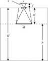
装置的测量模型如下:即利用图像中三个光点形成的面积s,求取液面高度h;如图4所示,设H为摄像头透镜到罐底的垂直距离,h为液面到罐底的距离(即液位),h’为摄像头透镜到液面的距离,有h’=H-h。利用三角形的相似关系有:The measurement model of the device is as follows: that is, use the area s formed by the three light spots in the image to obtain the height h of the liquid level; as shown in Figure 4, let H be the vertical distance from the camera lens to the bottom of the tank, and h be the distance from the liquid level to the tank The distance from the bottom (that is, the liquid level), h' is the distance from the camera lens to the liquid surface, and h'=H-h. The similarity relations using triangles are:
其中S1为三个光点在液面上所形成的三角形面积。Among them, S1 is the triangular area formed by the three light spots on the liquid surface.
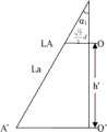
由于激光光源以摄像头的光心O按等边三角形进行安装,光心O在液面上的投影为O’,激光光束在液面上投影之间的夹角为120°,液面上三个激光点形成的面积为S1。如图5和图6所示,可求出
故液面三光点(A’,B’,C’)所形成的面积为:Therefore, the area formed by the three light points (A', B', C') on the liquid surface is:
为了求取液位高度h(或者是h’),我们必须对参数f,α1,α2,α3进行标定。In order to obtain the liquid level height h (or h'), we must calibrate the parameters f, α1 , α2 , and α3 .
参数标定Parameter Calibration
考虑到安装过程中摄像头成像平面与液面不严格平行,特引入一个新的参数β表征其夹角,以减少安装中对摄像头位置的垂直安装精度要求,同时它的引入还可以提高系统测量的精度,此时(1)式变成:Considering that the imaging plane of the camera is not strictly parallel to the liquid surface during the installation process, a new parameter β is introduced to characterize its angle to reduce the vertical installation accuracy requirements of the camera position during installation, and its introduction can also improve the measurement accuracy of the system. Accuracy, at this time (1) formula becomes:
当测量装置安装好后,当给定不同的液位为h1,h2,...hn时(或是h1’,h2’,...hn’),获取相应的储罐液体图像中三个光点所形成的面积s1,s2,...,sn,采用最小均方差法,计算参数f,α1,α2,α3与β。After the measuring device is installed, when different liquid levels are given as h1 , h2 , ...hn (or h1 ', h2 ', ... hn' ), the corresponding storage The area s1 , s2 , ..., sn formed by the three light spots in the liquid image of the tank is calculated using the minimum mean square error method to calculate the parameters f, α1 , α2 , α3 and β.
具体标定过程如下:The specific calibration process is as follows:
将(2)式带入(3)式,有:Bring (2) into (3), we have:
令:
将(4)式写成矩阵形式有:
进行标定时,我们将(5)可简化成MX=p;其中,When performing calibration, we simplify (5) into MX=p; where,
即X=M-1p,为求上述标定参数,利用最小均方差方法,使
进行液位测量时,公式(5)可化简为二元一次方程:When measuring the liquid level, the formula (5) can be simplified into a binary linear equation:
(m-s)·h′2+n·h′+u=0 .......(6)(ms)·h′2 +n·h′+u=0 ......(6)
带入图像处理获取的光点面积s,便求解出h’,液位高度h=H-h’即可求出。在求二元一次方程中,我们保留其中的正根作为液面高度参数。Bringing in the light spot area s obtained by image processing, h' can be obtained, and the liquid level height h=H-h' can be obtained. In seeking the binary linear equation, we retain the positive root as the liquid level parameter.
实施例Example
1)测量系统的安装1) Installation of the measurement system
我们选用摄像头的焦距为f=7.0mm,图像传感器靶面有效面积为4.8×3.6mm,采集图像分辨率为640×480,,水平视场为24°,垂直视场为18°。测试时,我们选用罐桶高为2m,直径为0.5m。首先将测量装置安装在罐桶的上端盖中心位置,测量装置中激光光源间距d选取5.7f,即d≈4cm。We choose the focal length of the camera as f=7.0mm, the effective area of the image sensor target surface is 4.8×3.6mm, the resolution of the collected image is 640×480, the horizontal field of view is 24°, and the vertical field of view is 18°. During the test, we choose the tank with a height of 2m and a diameter of 0.5m. First, the measuring device is installed at the center of the upper end cover of the tank, and the distance d of the laser light source in the measuring device is selected as 5.7f, that is, d≈4cm.
为了保证测量系统具有最佳的测量精度,我们将使激光束尽可能照射到罐桶底边缘,参考图2及图3的位置关系,这时有:In order to ensure that the measurement system has the best measurement accuracy, we will make the laser beam irradiate to the bottom edge of the tank as much as possible. Refer to the positional relationship in Figure 2 and Figure 3. At this time:

2)系统参数标定2) System parameter calibration
安装完成后,我们必须对参数f,α1,α2,α3,β等进行精确标定,标定时利用连通器测量罐桶液位,利用摄像头采集图像,获取图像中液面上的三个光点,并计算光点所围成的面积。我们获取的11组数据如下:After the installation is completed, we must accurately calibrate the parameters f, α1 , α2 , α3 , β, etc. During calibration, use the connector to measure the liquid level of the tank, use the camera to collect images, and obtain three points on the liquid surface in the image. light point, and calculate the area enclosed by the light point. The 11 sets of data we obtained are as follows:
(因为摄像头靶面面积为s0=4.8×3.6mm2=0.1728cm2;图像分辨率为:640*480;所以当利用图像像素点数s’进行表示时有:

根据公式(5)According to formula (5)
我们可获取标定的参数为:m=0.0093;n=0.5383;u=7.8404。The parameters we can obtain for calibration are: m=0.0093; n=0.5383; u=7.8404.
实际测试时,我们获图像三个光点所围成的面积中像素的个数为s’=29536,将其换算成s有:s=0.0166cm2将其带入式(6)有:可解得:h’=86.20cm(负根舍去),即h=113.8cm。During the actual test, we obtained that the number of pixels in the area surrounded by the three light spots of the image is s'=29536, and converting it into s has: s=0.0166cm2 Bringing it into formula (6) has: Solution: h'=86.20cm (the negative root is discarded), that is, h=113.8cm.
Claims (1)
Translated fromChinese


Priority Applications (1)
| Application Number | Priority Date | Filing Date | Title |
|---|---|---|---|
| CN2010105739257ACN102095469B (en) | 2010-12-04 | 2010-12-04 | Device and method for measuring liquid level in storage tank by utilizing camera |
Applications Claiming Priority (1)
| Application Number | Priority Date | Filing Date | Title |
|---|---|---|---|
| CN2010105739257ACN102095469B (en) | 2010-12-04 | 2010-12-04 | Device and method for measuring liquid level in storage tank by utilizing camera |
Publications (2)
| Publication Number | Publication Date |
|---|---|
| CN102095469A CN102095469A (en) | 2011-06-15 |
| CN102095469Btrue CN102095469B (en) | 2012-08-01 |
Family
ID=44128655
Family Applications (1)
| Application Number | Title | Priority Date | Filing Date |
|---|---|---|---|
| CN2010105739257AExpired - Fee RelatedCN102095469B (en) | 2010-12-04 | 2010-12-04 | Device and method for measuring liquid level in storage tank by utilizing camera |
Country Status (1)
| Country | Link |
|---|---|
| CN (1) | CN102095469B (en) |
Cited By (1)
| Publication number | Priority date | Publication date | Assignee | Title |
|---|---|---|---|---|
| US11183284B2 (en) | 2015-06-01 | 2021-11-23 | Digital Hospital, Inc. | Dosage confirmation apparatus |
Families Citing this family (14)
| Publication number | Priority date | Publication date | Assignee | Title |
|---|---|---|---|---|
| CN105091847B (en)* | 2014-04-16 | 2017-12-29 | 联想(北京)有限公司 | The method and electronic equipment of a kind of measurement distance |
| CN105806443B (en)* | 2014-12-30 | 2022-04-19 | 北京强度环境研究所 | Liquid level measuring system of shaking test storage tank |
| CN105526993B (en)* | 2016-01-29 | 2019-01-04 | 上海云鱼智能科技有限公司 | Machine vision level-sensing device and its method for measuring material position |
| CN110530449A (en)* | 2018-11-01 | 2019-12-03 | 永康市臣贸工贸有限公司 | Heeling condition oil measurement mechanism |
| CN110763306B (en)* | 2019-09-30 | 2020-09-01 | 中国科学院西安光学精密机械研究所 | Monocular vision-based liquid level measurement system and method |
| CN112504383A (en)* | 2020-09-04 | 2021-03-16 | 上海大学 | Image processing-based method for judging level in gauge in head-up mode |
| CN113064453B (en)* | 2021-02-21 | 2023-10-10 | 武汉市燃气热力规划设计院有限公司 | System and method for controlling levelness of upper surface of storage tank in storage tank manufacturing process |
| CN112875212A (en)* | 2021-03-18 | 2021-06-01 | 苏州市华创力自动化科技有限公司 | Stable control device of rail type liquid conveying system |
| CN114414000B (en)* | 2022-02-25 | 2025-08-26 | 贵州詹阳动力重工有限公司 | Fuel tank oil level detection method and device |
| CN114757889A (en)* | 2022-03-22 | 2022-07-15 | 中铁工程装备集团有限公司 | Air cushion bin of shield tunneling machine and liquid level detection method thereof |
| CN115112040A (en)* | 2022-07-04 | 2022-09-27 | 中国民航大学 | Vehicle-mounted airport runway surface snow depth measurement device based on laser spot image |
| CN115653729B (en)* | 2022-10-26 | 2025-01-28 | 东风商用车有限公司 | Engine oil consumption monitoring method, system and vehicle based on machine vision |
| CN116045808A (en)* | 2022-12-30 | 2023-05-02 | 江苏八麦尔智能科技有限公司 | 3D position and angle recognition device for fuel tank cap |
| CN118470028B (en)* | 2024-07-15 | 2024-10-25 | 湘江实验室 | Laser thickness measuring method and system |
Family Cites Families (6)
| Publication number | Priority date | Publication date | Assignee | Title |
|---|---|---|---|---|
| JP2000186952A (en)* | 1998-12-22 | 2000-07-04 | Atsushi Tominaga | Liquid level detector |
| KR100556612B1 (en)* | 2002-06-29 | 2006-03-06 | 삼성전자주식회사 | Position measuring device and method using laser |
| TW584714B (en)* | 2003-03-12 | 2004-04-21 | Ming-Chih Lu | Apparatus for measuring the height of stored devices |
| JP2008164573A (en)* | 2007-01-05 | 2008-07-17 | Nikon Corp | measuring device |
| CN201653497U (en)* | 2009-12-22 | 2010-11-24 | 中国矿业大学(北京) | A Coal Bunker Level Measuring Device Based on Laser and Monocular Vision |
| CN201926482U (en)* | 2010-12-04 | 2011-08-10 | 沈阳航空航天大学 | Storage tank liquid level measuring device utilizing camera |
- 2010
- 2010-12-04CNCN2010105739257Apatent/CN102095469B/ennot_activeExpired - Fee Related
Cited By (1)
| Publication number | Priority date | Publication date | Assignee | Title |
|---|---|---|---|---|
| US11183284B2 (en) | 2015-06-01 | 2021-11-23 | Digital Hospital, Inc. | Dosage confirmation apparatus |
Also Published As
| Publication number | Publication date |
|---|---|
| CN102095469A (en) | 2011-06-15 |
Similar Documents
| Publication | Publication Date | Title |
|---|---|---|
| CN102095469B (en) | Device and method for measuring liquid level in storage tank by utilizing camera | |
| CN207318710U (en) | A kind of more harness hybrid laser radars of list laser | |
| CN102012359B (en) | A liquid multi-parameter sensor | |
| CN101387538B (en) | Linear array CCD transmissive liquid level measuring method and measuring device | |
| CN204831220U (en) | Calcirm -fluoride optical flat two sides depth of parallelism high accuracy testing arrangement | |
| CN101504302B (en) | Transceiver-integrated linear array CCD optical liquid level measurement method and measurement device | |
| CN101922932B (en) | Compensating device of pyramid prism coordinate measuring error | |
| CN101782419B (en) | Liquid level measuring method and measuring device based on isosceles right-angled triangular prism | |
| CN203190948U (en) | Device for detecting thickness of transparent substrate | |
| CN111189512A (en) | Device and method for measuring liquid level and refractive index of transparent liquid based on laser ranging | |
| CN108981589B (en) | A device and method for measuring the height of a cup mouth | |
| CN106168461A (en) | A kind of novel telemeasurement calibration instrument | |
| CN110132160A (en) | A bridge deflection measurement method using fiber optic light source | |
| CN104777133B (en) | A kind of self-alignment refractometer | |
| CN101762567A (en) | Differential solution concentration measuring device and method | |
| CN101479564A (en) | Apparatus and method for measuring sidewall thickness of non-round transparent containers | |
| CN102435259A (en) | Linear array CCD (Charge Coupled Device) liquid level measurement device with isolated gate and measurement method | |
| CN107478306A (en) | A kind of storage tank liquid-level meter field calibration device | |
| CN101509802B (en) | Optical total reflection linear array CCD liquid level measuring method and measuring device | |
| CN101788320A (en) | Bevel edge type liquid level measurement method and device based on isosceles right triangular prism | |
| CN201926482U (en) | Storage tank liquid level measuring device utilizing camera | |
| CN107246902A (en) | The method for detecting liquid level and system of a kind of 3D printing fluent material | |
| CN207301331U (en) | A kind of trigonometry laser range sensor | |
| CN104949739A (en) | Straight-line benchmark structure for field calibration of large-size liquid level sensor | |
| CN201034557Y (en) | On-line imaging detection device for machining accuracy of inner and outer walls of cylinder |
Legal Events
| Date | Code | Title | Description |
|---|---|---|---|
| C06 | Publication | ||
| PB01 | Publication | ||
| C10 | Entry into substantive examination | ||
| SE01 | Entry into force of request for substantive examination | ||
| C14 | Grant of patent or utility model | ||
| GR01 | Patent grant | ||
| C17 | Cessation of patent right | ||
| CF01 | Termination of patent right due to non-payment of annual fee | Granted publication date:20120801 Termination date:20121204 |