CN102089883A - solar power plant - Google Patents
solar power plantDownload PDFInfo
- Publication number
- CN102089883A CN102089883ACN2008801302514ACN200880130251ACN102089883ACN 102089883 ACN102089883 ACN 102089883ACN 2008801302514 ACN2008801302514 ACN 2008801302514ACN 200880130251 ACN200880130251 ACN 200880130251ACN 102089883 ACN102089883 ACN 102089883A
- Authority
- CN
- China
- Prior art keywords
- circuit
- solar battery
- solar cell
- attenuation
- periodic signal
- Prior art date
- Legal status (The legal status is an assumption and is not a legal conclusion. Google has not performed a legal analysis and makes no representation as to the accuracy of the status listed.)
- Granted
Links
Images


Classifications
- H—ELECTRICITY
- H10—SEMICONDUCTOR DEVICES; ELECTRIC SOLID-STATE DEVICES NOT OTHERWISE PROVIDED FOR
- H10F—INORGANIC SEMICONDUCTOR DEVICES SENSITIVE TO INFRARED RADIATION, LIGHT, ELECTROMAGNETIC RADIATION OF SHORTER WAVELENGTH OR CORPUSCULAR RADIATION
- H10F77/00—Constructional details of devices covered by this subclass
- H10F77/95—Circuit arrangements
- H10F77/953—Circuit arrangements for devices having potential barriers
- H10F77/955—Circuit arrangements for devices having potential barriers for photovoltaic devices
- Y—GENERAL TAGGING OF NEW TECHNOLOGICAL DEVELOPMENTS; GENERAL TAGGING OF CROSS-SECTIONAL TECHNOLOGIES SPANNING OVER SEVERAL SECTIONS OF THE IPC; TECHNICAL SUBJECTS COVERED BY FORMER USPC CROSS-REFERENCE ART COLLECTIONS [XRACs] AND DIGESTS
- Y02—TECHNOLOGIES OR APPLICATIONS FOR MITIGATION OR ADAPTATION AGAINST CLIMATE CHANGE
- Y02E—REDUCTION OF GREENHOUSE GAS [GHG] EMISSIONS, RELATED TO ENERGY GENERATION, TRANSMISSION OR DISTRIBUTION
- Y02E10/00—Energy generation through renewable energy sources
- Y02E10/50—Photovoltaic [PV] energy
Landscapes
- Photovoltaic Devices (AREA)
- Charge And Discharge Circuits For Batteries Or The Like (AREA)
- Life Sciences & Earth Sciences (AREA)
- Engineering & Computer Science (AREA)
- Sustainable Development (AREA)
- Sustainable Energy (AREA)
Abstract
Translated fromChineseDescription
Translated fromChinese技术领域technical field
本发明涉及太阳光发电装置,特别是涉及为了得到期望的电力而使用多个太阳能电池单元构成的太阳光发电装置的故障检测方法。The present invention relates to a photovoltaic power generation device, and more particularly to a method for detecting a failure of a photovoltaic power generation device configured using a plurality of solar battery cells in order to obtain desired power.
背景技术Background technique
在使用了太阳能电池单元的太阳光发电装置中,为了得到期望的电力,将串联连接搭载了太阳能电池单元的太阳能电池模块而构成的太阳能电池串进行了并联连接。此处,在太阳能电池模块中搭载的太阳能电池单元发生故障、或者太阳光被遮断而使太阳能电池单元的电动势成为规定值以下的情况下,为了防止妨碍到与该太阳能电池单元串联连接的其他太阳能电池单元的通电,针对将1个以上的太阳能电池单元电气性地进行串联或者并联连接的每个连接单位,并联连接旁路电路(bypass circuit)。In a photovoltaic power generation device using solar cells, in order to obtain desired electric power, solar cell strings constituted by serially connecting solar cell modules equipped with solar cells are connected in parallel. Here, when a solar cell installed in a solar cell module fails or sunlight is blocked and the electromotive force of the solar cell becomes lower than a specified value, in order to prevent interference with other solar cells connected in series with the solar cell, For the energization of the battery cells, a bypass circuit (bypass circuit) is connected in parallel for each connection unit in which one or more solar battery cells are electrically connected in series or in parallel.
在该旁路电路中设置有旁路二极管,在太阳能电池单元正常发电的情况下,该太阳能电池单元的电动势作为逆偏置电压而被施加到旁路二极管,从而将旁路二极管保持为遮断状态,使旁路电路的旁路动作停止,使得不经由旁路电路而可以从太阳能电池单元取出电力。A bypass diode is provided in the bypass circuit, and when the solar battery cell is generating electricity normally, the electromotive force of the solar battery cell is applied to the bypass diode as a reverse bias voltage, thereby keeping the bypass diode in a blocking state. , the bypass operation of the bypass circuit is stopped, so that electric power can be taken out from the solar cell without passing through the bypass circuit.
另外,如果在太阳能电池串内的一部分的太阳能电池单元中产生断线、电动势降低等异常,导致该太阳能电池单元无法正常发电,则来自该太阳能电池串内的正常的太阳能电池单元的电流经由与异常的太阳能电池单元并联的旁路二极管而流过,从而绕过该异常的太阳能电池单元,防止由于某一处的太阳能电池单元的异常而无法使用太阳能电池串内的所有太阳能电池单元的情形。In addition, if an abnormality such as disconnection or drop in electromotive force occurs in a part of the solar battery cells in the solar battery string, causing the solar battery cells to fail to generate electricity normally, the current from the normal solar battery cells in the solar battery string passes through and An abnormal solar battery unit is connected in parallel with a bypass diode to bypass the abnormal solar battery unit, preventing the situation that all the solar battery units in the solar battery string cannot be used due to an abnormality of a certain solar battery unit.
另外,在太阳能电池单元中产生了故障的情况下,通过更换搭载了该太阳能电池单元的太阳能电池模块,可以确保太阳光发电装置的原来的发电量。作为这样的探测太阳能电池单元的故障的方法,已知探测向旁路电路的通电动作的方法。In addition, when a failure occurs in a solar battery cell, the original power generation amount of the photovoltaic power generation device can be ensured by replacing the solar battery module in which the solar battery cell is mounted. As a method of detecting failure of such a solar battery cell, a method of detecting an energization operation to a bypass circuit is known.
另外,作为探测太阳能电池单元的故障的方法,有如下方法:对并联连接的各太阳能电池串的输出电压进行比较,判断为在输出电压低的太阳能电池串内的太阳能电池模块中的某一个中存在异常(专利文献1)。In addition, as a method of detecting a failure of a solar battery cell, there is a method of comparing the output voltages of the solar battery strings connected in parallel, and judging that there is a fault in any of the solar battery modules in the solar battery string with a low output voltage. There is an abnormality (Patent Document 1).
另外,有如下方法:在旁路电路的中途设置发光二极管等的发光体等,在旁路电路中流过了电流的情况下使发光体发光,从而容易地检测太阳能电池面板的故障、电动势不足(专利文献2)。In addition, there is a method of installing light-emitting bodies such as light-emitting diodes in the middle of the bypass circuit, and making the light-emitting bodies emit light when a current flows through the bypass circuit, thereby easily detecting failure of the solar battery panel or insufficient electromotive force ( Patent Document 2).
另外,有如下方法:在旁路电路的中途设置电流检测继电器,经由通信线对该继电器动作进行远程监视(专利文献3)。In addition, there is a method of installing a current detection relay in the middle of a bypass circuit, and remotely monitoring the operation of the relay through a communication line (Patent Document 3).
另外,有如下方法:针对每个太阳能电池模块设置特定频率发送电路,根据太阳能电池模块是否正常发电,而使特定频率的信号重叠到连接太阳能电池模块之间的电力线中(专利文献4)。即,在该方法中,在太阳能电池模块的电压为一定电压以上的正常时,从太阳能电池模块向特定频率发送电路供给电力,从而可以使特定频率的信号重叠到电力线中而发送,如果在故障时等太阳能电池模块的电压成为一定电压以下,则停止向特定频率发送电路供给电力,从而不将特定频率的信号重叠到电力线中而发送,通过信号分离设备从电力线中取出特定频率的信号,从而可以判定太阳能电池模块有无故障、有无电动势不足。In addition, there is a method of providing a specific frequency transmission circuit for each solar cell module, and superimposing a signal of a specific frequency on the power line connecting the solar cell modules depending on whether the solar cell modules are normally generating power (Patent Document 4). That is, in this method, when the voltage of the solar cell module is at a certain voltage or higher, power is supplied from the solar cell module to the transmission circuit of a specific frequency, so that a signal of a specific frequency can be superimposed on the power line and transmitted. When the voltage of the solar cell module falls below a certain voltage, the power supply to the specific frequency transmission circuit is stopped, so that the signal of the specific frequency is not superimposed on the power line and transmitted, and the signal of the specific frequency is extracted from the power line by the signal separation device, thereby It is possible to determine whether there is a failure in the solar battery module or whether there is insufficient electromotive force.
另外,在该方法中,通过针对每个太阳能电池模块改变特定频率发送电路的发送频率,可以确定故障、电动势不足的太阳能电池模块。另外,特定频率发送电路在太阳能电池模块动作的期间并非始终发送信号,而是按照30分钟间隔、1小时间隔、1日间隔等定期地发送信号,从而可以抑制发送所需的功耗。In addition, in this method, by changing the transmission frequency of the specific frequency transmission circuit for each solar battery module, it is possible to specify a solar battery module that is faulty or has insufficient electromotive force. In addition, the specific frequency transmission circuit does not always transmit signals during the operation of the solar cell module, but regularly transmits signals at intervals of 30 minutes, one hour, one day, etc., thereby reducing the power consumption required for transmission.
专利文献1:日本特开平08-185235号公报Patent Document 1: Japanese Patent Application Laid-Open No. 08-185235
专利文献2:日本特开平08-97456号公报Patent Document 2: Japanese Patent Application Laid-Open No. 08-97456
专利文献3:日本特开平09-102622号公报Patent Document 3: Japanese Patent Application Laid-Open No. 09-102622
专利文献4:日本特开2000-269531号公报Patent Document 4: Japanese Patent Laid-Open No. 2000-269531
发明内容Contents of the invention
但是,根据所述以往的专利文献1的技术,即使在太阳能电池模块中的某一个发生了断路故障、电动势不足的情况下,对太阳能电池串全体的输出电压造成的影响也是轻微的,由于太阳能电池模块的个体差、设置场所所致的日照量的差异、变动等,输出电压也会变化。因此,存在如下问题:仅通过监视太阳能电池串的输出电压的变动,难以稳定地判别有无太阳能电池模块的断路故障、电动势不足。However, according to the technique of the above-mentioned
另外,根据所述以往的专利文献2的技术,为了检测太阳能电池面板的故障、电动势不足,需要目视确认发光体的发光。因此,存在如下问题:难以实现太阳能电池面板的故障检测的自动化,并且在太阳能电池模块设置于屋顶上、远方的情况下,发光的目视确认自身变得困难,对太阳能电池面板的故障检测造成障碍。In addition, according to the technique of the above-mentioned
另外,根据所述以往的专利文献3的技术,存在如下问题:针对每个旁路电路需要设置电流检测继电器,并且需要与电力线分开地设置对于电流检测继电器的动作进行通信的信号线,导致成本上升。In addition, according to the technique of the above-mentioned
另外,根据所述以往的专利文献4的技术,存在如下问题:针对每个太阳能电池模块需要设置特定频率发送电路以及电气性参数探测设备,不仅导致成本上升,而且在太阳能电池模块的正常时,特定频率发送电路始终发送信号,所以导致功耗的增大。In addition, according to the technique of the above-mentioned
另外,为了抑制该功耗,在采用了定期地发送信号的方法的情况下,需要针对每个太阳能电池模块设置定时器、时钟,或者需要针对每个太阳能电池模块连接对发送开始以及发送停止定期地进行指示的信号线,所以存在导致成本上升的问题。In addition, in order to suppress this power consumption, when a method of periodically transmitting a signal is adopted, it is necessary to set a timer or a clock for each solar cell module, or to periodically start and stop transmission for each solar cell module connection. Since there is a signal line for instructing ground, there is a problem of causing an increase in cost.
另外,根据所述以往的专利文献1~4的技术,作为故障探测动作所需的电力,使用了由太阳能电池模块产生的发电电力,所以存在如下问题:在发电电力少时,无法得到故障探测动作所需的充分的电力,故障探测动作变得不稳定。In addition, according to the techniques of the above-mentioned
本发明是鉴于所述问题而完成的,目的在于得到一种太阳光发电装置,不会针对每个旁路电路消耗由太阳能电池模块产生的发电电力,而可以稳定地探测太阳能电池模块的异常。The present invention was made in view of the above problems, and an object of the present invention is to obtain a photovoltaic power generation device capable of stably detecting abnormalities of solar cell modules without consuming power generated by solar cell modules for each bypass circuit.
为了解决所述课题,并达成目的,本发明的太阳光发电装置具备:太阳能电池单元,通过电气性地串联或者并联连接1个以上而构成连接单位;以及旁路电路,针对每个所述连接单位并联连接,在所述连接单位的电动势是规定值以下时对所述连接单位进行旁路而进行通电动作,通过电气性地串联连接1台以上的太阳能电池模块而构成太阳能电池串,并通过电力线并联连接了1列以上的所述太阳能电池串,其中,所述太阳能电池模块搭载了1组以上的所述连接单位和旁路电路的组合,所述太阳光发电装置的特征在于,具备:发送电路,将规定振幅的发送信号送出到所述电力线;接收电路,经由所述太阳能电池串接收送出到所述电力线的发送信号;以及衰减电路,设置于所述旁路电路,使所述发送信号的振幅衰减。In order to solve the above-mentioned problems and achieve the object, the photovoltaic power generation device of the present invention includes: one or more solar battery cells electrically connected in series or in parallel to form a connection unit; and a bypass circuit for each of the connections. The units are connected in parallel, and when the electromotive force of the connected unit is equal to or less than a predetermined value, the connected unit is bypassed to perform an energization operation, and a solar battery string is formed by electrically connecting one or more solar battery modules in series, and by The power line is connected in parallel with one or more rows of solar cell strings, wherein the solar cell module is equipped with a combination of at least one connection unit and a bypass circuit, and the solar power generation device is characterized in that it includes: a transmission circuit for sending a transmission signal of a predetermined amplitude to the power line; a reception circuit for receiving the transmission signal sent to the power line via the solar battery string; and an attenuation circuit provided in the bypass circuit to make the transmission The amplitude of the signal is attenuated.
根据本发明,起到如下效果:不会针对每个旁路电路消耗由太阳能电池模块产生的发电电力,而可以稳定地探测太阳能电池模块的异常。According to the present invention, there is an effect that an abnormality of a solar cell module can be stably detected without consuming generated power generated by the solar cell module for each bypass circuit.
附图说明Description of drawings
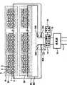
图1是示出本发明的太阳光发电装置的实施例1的概要结构的框图。FIG. 1 is a block diagram showing a schematic configuration of
图2是示出在图1的太阳能电池单元1中的任意一个中都没有发生故障时的周期信号的波形的图。FIG. 2 is a diagram showing a waveform of a periodic signal when no failure occurs in any of the
图3是示出在图1的太阳能电池单元1中的某一个中发生了故障时的周期信号的波形的图。FIG. 3 is a diagram showing a waveform of a periodic signal when a failure occurs in any of the
图4是示出图1的发送电路14的结构例的框图。FIG. 4 is a block diagram showing a configuration example of the
图5是示出图1的衰减电路4的第1结构例的框图。FIG. 5 is a block diagram showing a first configuration example of the
图6是示出图1的衰减电路4的第2结构例的框图。FIG. 6 is a block diagram showing a second configuration example of the
图7是示出本发明的太阳光发电装置的实施例2的概要结构的框图。Fig. 7 is a block diagram showing a schematic configuration of
图8是示出本发明的太阳光发电装置的实施例3中应用的旁路电力线9的结构例的框图。FIG. 8 is a block diagram showing a configuration example of a bypass power line 9 applied in
图9是示出本发明的太阳光发电装置的实施例4的概要结构的框图。Fig. 9 is a block diagram showing a schematic configuration of
(附图标记说明)(Description of Reference Signs)
1:太阳能电池单元;2:连接单位;3:旁路电路;4、32A、32B:衰减电路;5:旁路二极管;6:太阳能电池模块;7A、7B:太阳能电池串;8、8A、8B:电力线;9A:旁路电力线;10:连接箱;11:交流线;12:逆变器;13A、13B:逆流防止二极管;14:发送电路;15:接收电路;16:线圈;17:发送开关;18:周期电源;19:判定电路;30、36:电容器;31、37:电阻器;33A、33B:开闭器;34、35:切换开关;41:控制电路。1: Solar battery unit; 2: Connection unit; 3: Bypass circuit; 4, 32A, 32B: Attenuation circuit; 5: Bypass diode; 6: Solar battery module; 7A, 7B: Solar battery string; 8, 8A, 8B: power line; 9A: bypass power line; 10: connection box; 11: AC line; 12: inverter; 13A, 13B: reverse current prevention diode; 14: sending circuit; 15: receiving circuit; 16: coil; 17: 18: cycle power supply; 19: decision circuit; 30, 36: capacitor; 31, 37: resistor; 33A, 33B: switch; 34, 35: switch; 41: control circuit.
具体实施方式Detailed ways
以下,根据附图,详细说明本发明的太阳光发电装置的实施例。另外,本发明不限于该实施例。Hereinafter, embodiments of the photovoltaic power generation device of the present invention will be described in detail with reference to the drawings. In addition, this invention is not limited to this Example.
实施例1Example 1
图1是示出本发明的太阳光发电装置的实施例1的概要结构的框图。在图1中,在太阳光发电装置中,设置有分别电气性地串联连接了太阳能电池模块6而得到的太阳能电池串7A、7B。另外,太阳能电池模块6可以构成硬件方式的分离单位,可以针对每个太阳能电池模块6进行设置或进行更换。FIG. 1 is a block diagram showing a schematic configuration of
另外,从太阳能电池串7A、7B分别引出电力线8A、8B,这些电力线8A、8B共同地连接到电力线8,从而并联连接太阳能电池串7A、7B。In addition,
此处,在太阳能电池模块6中,设置有通过太阳光而产生电的太阳能电池单元1以及旁路电路3,将1个以上的太阳能电池单元1电气性地串联或者并联连接从而构成连接单位2。并且,对连接单位2并联连接了旁路电路3,旁路电路3可以在连接单位2的电动势为规定值以下时对连接单位2进行旁路而进行通电动作。Here, the
另外,在太阳光发电装置中,设置有将电力线8连接到逆变器12的连接箱10、将直流变换为交流的逆变器12。另外,电力线8经由连接箱10而与逆变器12连接,从逆变器12引出了输出交流的交流线11。此处,在连接箱10中,设置有逆流防止二极管13A、13B,逆流防止二极管13A、13B分别串联连接到太阳能电池串7A、7B的电流流出侧。In addition, in the photovoltaic power generation device, a
另外,在太阳光发电装置中,设置有发送电路14、接收电路15以及判定电路19。另外,发送电路14在连接箱10与逆变器12之间连接到向太阳能电池串7A、7B的电流流入侧的电力线8上,接收电路15在连接箱10与逆变器12之间连接到向太阳能电池串7A、7B的电流流出侧的电力线8上。另外,判定电路19与接收电路15连接。In addition, in the photovoltaic power generation device, a
此处,发送电路14可以将规定振幅的发送信号送出到电力线8。另外,作为发送信号,可以使用规定频率的周期信号。接收电路15可以经由太阳能电池串7A、7B接收从发送电路14送出到电力线8的发送信号。另外,接收电路15由电压计、电流计、CT变换器等构成,可以进行模拟数字变换,探测周期信号。或者,既可以使用傅立叶变换等算法来检测周期信号,也可以使用频谱分析器等。Here, the
判定电路19在探测到由接收电路15接收到的发送信号的振幅衰减了规定值以上的情况下,可以判定为直流电力通过了旁路电路3。或者,判定电路19也可以在连续一定时间以上探测到由接收电路15接收到的发送信号的振幅衰减了规定值以上的情况下,判定为直流电力通过了旁路电路3。The
另外,在旁路电路3中,设置有衰减电路4以及旁路二极管5,衰减电路4与旁路二极管5相互串联连接。并且,衰减电路4和旁路二极管5的串联电路以使旁路二极管5的阴极与太阳能电池单元1的电流流出侧连接的方式,与连接单位2并联连接。此处,衰减电路4可以使从发送电路14送出到电力线8上的发送信号的振幅衰减。另外,作为衰减电路4,例如可以使用低通滤波器、带通滤波器。In addition, the
此处,从发送电路14送出的周期信号可以具有多个频率分量。另外,在周期信号中具有多个频率分量的情况下,可以分时(Time Sharing)地使周期信号具有这些频率分量。Here, the periodic signal sent from the
并且,能够以使通过衰减电路4被衰减的周期信号的频率针对每个太阳能电池模块6相互不同的方式,设定衰减电路4的衰减特性。例如,能够以与太阳能电池模块6的个数对应的方式,设定周期信号的频率分量的个数。并且,能够以使通过衰减电路4被衰减的周期信号的频率针对每个太阳能电池模块6不同的方式,设定衰减电路4的衰减特性。Furthermore, the attenuation characteristic of the
或者,也可以针对太阳能电池串7A、7B的每一个,设定周期信号的频率以及衰减电路4的衰减特性。例如,使周期信号具有F1、F2(F2>F1)这样的频率之后,能够以使频率为F1的周期信号衰减的方式设定太阳能电池串7A的衰减电路4的衰减特性,以使频率为F2的周期信号衰减的方式设定太阳能电池串7B的衰减电路4的衰减特性。Alternatively, the frequency of the periodic signal and the attenuation characteristic of the
另外,在以下的说明中,使周期信号具有F1、F2这样的频率之后,以使频率为F1的周期信号衰减的方式设定太阳能电池串7A的衰减电路4的衰减特性、以使频率为F2的周期信号衰减的方式设定太阳能电池串7B的衰减电路4的衰减特性的情况为例子进行说明,但周期信号所具有的频率并不一定被限定于2种频率,既可以具有3种频率,也可以与其对应地针对太阳能电池串7A、7B的每一个或者每个太阳能电池模块6设定衰减电路4的衰减特性。In addition, in the following description, after the periodic signal has frequencies F1 and F2, the attenuation characteristic of the
并且,如果太阳光照射到太阳能电池单元1,则在太阳能电池单元1中产生电动势,通过该电动势而产生的电流向一定的方向流过,并且与在太阳能电池串7A、7B中分别串联连接的太阳能电池单元1的个数相应的直流电压经由电力线8被供给到逆变器12。并且,如果直流电压经由电力线8而被供给到逆变器12,则该直流电压通过逆变器12变换为交流电压,并经由交流线11输出。And, when sunlight irradiates the
另外,从发送电路14例如生成具有频率F1、F2的周期信号,具有频率F1、F2的周期信号被分时地送出到电力线8上,并分别经由电力线8A、8B输入到太阳能电池串7A、7B。In addition, for example, periodic signals with frequencies F1 and F2 are generated from the
并且,如果输入到太阳能电池串7A、7B的周期信号通过了太阳能电池串7A、7B,则经由电力线8被输入到接收电路15。并且,在接收电路15中,针对频率F1、F2的每一个,探测从发送电路14送出的周期信号的衰减量。Then, the periodic signal input to the solar cell strings 7A, 7B passes through the solar cell strings 7A, 7B, and then is input to the receiving
此处,在太阳能电池单元1中产生了规定值以上的电动势的情况下,旁路二极管5被施加逆偏置电压。因此,旁路二极管5被保持为遮断状态,不会进行旁路电路3的旁路动作,从太阳能电池单元1产生的电动势被供给到逆变器12。另外,在旁路二极管5被保持为遮断状态的情况下,从发送电路14送出的周期信号不会通过太阳能电池串7A、7B中的任意一个的衰减电路4,而到达接收电路15。因此,在接收电路15中,探测到从发送电路14送出的周期信号的衰减量大致为0。并且,在探测到从发送电路14送出的周期信号的衰减量大致为0的情况下,判定电路19判定为对太阳能电池串7A、7B中的任意一个的旁路电路3都没有通电直流电力,判断为在太阳能电池串7A、7B中的任意一个的太阳能电池模块6中都没有无法恢复的故障。Here, when an electromotive force equal to or greater than a predetermined value is generated in the
另一方面,在太阳能电池串7A中的某一个太阳能电池模块6的太阳能电池单元1中产生了断线等故障的情况下,从该太阳能电池单元1产生的电动势成为规定值以下。并且,如果从太阳能电池串7A中的某一个太阳能电池单元1产生的电动势成为规定值以下,则经由与由该太阳能电池单元1构成的连接单位2并联连接的旁路电路3内的旁路二极管5而流过电流,从没有产生故障的太阳能电池单元1产生的电动势被供给到逆变器12。On the other hand, when a failure such as a disconnection occurs in the
另外,在太阳能电池串7A中,如果经由与由产生了故障的太阳能电池单元1构成的连接单位2并联连接的旁路电路3内的旁路二极管5而流过电流,则在该旁路电路3内的衰减电路4中也流过电流,从发送电路14送出的周期信号经由与由产生了故障的太阳能电池单元1构成的连接单位2并联连接的旁路电路3内的衰减电路4而到达接收电路15。In addition, in the
因此,在接收电路15中,对于从发送电路14送出的周期信号中的频率为F1的分量,探测为其衰减量超过规定值,并且对于频率为F2的分量,探测为其衰减量大致为0。并且,在探测到周期信号的频率为F1的分量的衰减量超过规定值的情况下,判定电路19判定为对太阳能电池串7A中的某一个旁路电路3通电了直流电力,判断为在太阳能电池串7A中的某一个太阳能电池模块6中存在无法恢复的故障。Therefore, the receiving
另外,在太阳能电池串7B中的某一个太阳能电池模块6的太阳能电池单元1中产生了断线等故障的情况下,从该太阳能电池单元1产生的电动势成为规定值以下。并且,如果从太阳能电池串7B中的某一个太阳能电池单元1产生的电动势成为规定值以下,则经由与由该太阳能电池单元1构成的连接单位2并联连接的旁路电路3内的旁路二极管5而流过电流,从没有产生故障的太阳能电池单元1产生的电动势被供给到逆变器12。In addition, when a failure such as a disconnection occurs in the
另外,在太阳能电池串7B中,如果经由与由产生了故障的太阳能电池单元1构成的连接单位2并联连接的旁路电路3内的旁路二极管5而流过电流,则在该旁路电路3内的衰减电路4中也流过电流,从发送电路14送出的周期信号经由与由产生了故障的太阳能电池单元1构成的连接单位2并联连接的旁路电路3内的衰减电路4而到达接收电路15。In addition, in the
因此,在接收电路15中,对于从发送电路14送出的周期信号中的频率为F2的分量,探测为其衰减量超过规定值,并且对于频率为F1的分量,探测为其衰减量大致为0。并且,在探测到周期信号的频率为F2的分量的衰减量超过规定值的情况下,判定电路19判定为对太阳能电池串7B中的某一个旁路电路3通电了直流电力,判断为在太阳能电池串7B中的某一个太阳能电池模块6中存在无法恢复的故障。Therefore, the receiving
另外,在太阳光的日照量减少了的情况下,也对旁路电路3通电直流电力,但在日照量恢复的情况下太阳能电池单元1自然恢复。因此,为了防止在太阳光的日照量减少了的情况下错误判定为太阳能电池模块6发生了故障,也可以在一定的期间、在同一处连续判定为对旁路电路3通电了直流电力的情况下,判断为在太阳能电池串7A、B中的某一个的太阳能电池模块6中存在无法恢复的故障。Also, when the amount of solar radiation decreases, the
另外,例如,太阳能电池串7A全体在阴暗处、或者在太阳能电池串7A的太阳能电池模块6中产生了故障,从而由太阳能电池串7A产生的电压降低而在太阳能电池串7A、7B之间产生了电压差的情况下,通过逆流防止二极管13A来防止从太阳能电池串7B输出的电流逆向流过太阳能电池串7A的现象。因此,通过设置逆流防止二极管13A,即使在太阳能电池串7A无法取出直流电力的情况下,也可以从太阳能电池串7B取出直流电力。对于逆流防止二极管13B也同样。In addition, for example, if the entire
由此,不用针对每个旁路电路3设置电流检测继电器、特定频率发送电路等,而可以探测太阳能电池模块6的故障,并且能够通过对发送电路14以及接收电路15供给电力而进行故障的监视,无需对衰减电路4供给电力,所以可以抑制功耗以及成本的增大,并且即使在太阳能电池模块设置于屋顶上、远方的情况下,也可以稳定并且容易地检测太阳能电池模块的异常。Thereby, without providing a current detection relay, a specific frequency transmission circuit, etc. for each
另外,在图1的实施例1中,示出了将太阳能电池串7A、7B并联连接了2列的结构,但太阳能电池串的并联数不限于2列,只要是将太阳能电池串并联连接了1列以上的结构,就可以是任意列。另外,在图1的实施例1中,示出了在连接单位2中设置2个太阳能电池单元1的结构,但构成连接单位2的太阳能电池单元1不限于2个,只要是在连接单位2中设置了1个以上的太阳能电池单元1的结构,就可以是任意个数。另外,在图1的实施例1中,示出了在太阳能电池模块6中设置了2个连接单位2的结构,但太阳能电池模块6中设置的连接单位2不限于2个,只要是在太阳能电池模块6中设置了1个以上的连接单位2的结构,就可以是任意个数。In addition, in
另外,在图1的实施例1中,使周期信号具有F1、F2这样的2种频率之后,以使频率F1、F2的周期信号分别衰减的方式设定了太阳能电池串7A、7B的衰减电路4的衰减特性的情况为例子进行了说明,但在太阳能电池串有N(N是1以上的整数)个的情况下,也可以使周期信号具有F1~FN这样的N种频率之后,以使频率F1~FN的周期信号分别衰减的方式设定N个太阳能电池串的衰减电路4的衰减特性。In addition, in
或者,在太阳能电池串是N个、并在各太阳能电池串中仅有M(M是1以上的整数)个太阳能电池模块的情况下,也可以使周期信号具有F11~FMN这样的M×N种频率之后,以使频率F11~FMN的周期信号分别衰减的方式,设定M×N台的太阳能电池模块的衰减电路4的衰减特性。Alternatively, when there are N solar battery strings and there are only M (M is an integer greater than 1) solar battery modules in each solar battery string, the periodic signal can also have M×N such as F11 to FMN. After the frequencies are selected, the attenuation characteristics of the
另外,也可以在逆变器12或者连接箱10内内置发送电路14以及接收电路15,也可以应用于多个逆变器12与电力线8连接的结构。In addition, the
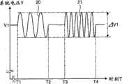
图2是示出在图1的太阳能电池单元1中的任意一个中都没有产生故障时的周期信号的波形的图。另外,系统电压V是与图1的逆变器12连接的电力线8的两端的电压。FIG. 2 is a diagram showing a waveform of a periodic signal when no failure occurs in any of the
在图2中,如果在图1的太阳能电池单元1中的任意一个中都没有产生故障的情况下的系统电压V是V1,则频率F1、F2的周期信号从发送电路14分时地送出到电力线8,从而在时刻T1~T2的期间对系统电压V1重叠频率为F1且振幅为ΔV1的周期信号20,并输入到太阳能电池串7A、7B,并且在时刻T3~T4的期间对系统电压V1重叠频率为F2且振幅为ΔV1的周期信号21,并输入到太阳能电池串7A、7B。In FIG. 2, if the system voltage V is V1 when no failure occurs in any of the
然后,在图1的太阳能电池单元1中的任意一个中都没有产生故障的情况下,从发送电路14送出的周期信号20、21不会通过太阳能电池串7A、7B中的任意一个的衰减电路4,而到达接收电路15。因此,在接收电路15中,从发送电路14送出的周期信号20、21的振幅被探测大致为ΔV1,判定为周期信号20、21的衰减量大致为0。然后,在判定为从发送电路14送出的周期信号的衰减量大致为0的情况下,判定电路19可以判定为没有对旁路电路3通电直流电力,可以判断为在太阳能电池串7A、7B中的任意一个的太阳能电池模块6中都没有无法恢复的故障。Then, when there is no failure in any of the
图3是示出在图1的太阳能电池单元1中的某一个中产生了故障时的周期信号的波形的图。在图3中,例如,在太阳能电池串7B中的某一个太阳能电池模块6的太阳能电池单元1中产生了断线等故障的情况下,从该太阳能电池单元1产生的电动势成为规定值以下。因此,与由该太阳能电池单元1构成的连接单位2并联连接的旁路电路3被通电,来自该连接单位2的电动势不会对系统电压V作出贡献,所以系统电压V成为比V1低的V2。FIG. 3 is a diagram showing a waveform of a periodic signal when a failure occurs in any of the
另外,如果与由产生了故障的太阳能电池单元1构成的连接单位2并联连接的旁路电路3通电,则在该旁路电路3内的衰减电路4中也流过电流,从发送电路14送出的周期信号20、21通过该衰减电路4而被衰减后到达接收电路15。In addition, if the
此处,如果太阳能电池串7B侧的衰减电路4的衰减特性被设定为在频率F2下衰减量变大、并在频率F1下衰减量变小,则在接收电路15中探测到从发送电路14送出的周期信号20的振幅为ΔV1a、周期信号21的振幅为ΔV2(ΔV1a>ΔV2)。Here, if the attenuation characteristic of the
另外,在图1的实施方式中,太阳能电池串7A、7B为2并联,周期信号21通过太阳能电池串7B的衰减电路4而衰减,但由于不通过太阳能电池串7A的衰减电路4所以不会被衰减。因此,在太阳能电池串7B的太阳能电池单元1中产生了故障时的周期信号21的振幅ΔV2成为在太阳能电池串7B的太阳能电池单元1中没有产生故障时的周期信号21的振幅ΔV1的一半程度。In addition, in the embodiment shown in FIG. 1 , the
并且,探测到周期信号21的振幅为ΔV2的结果,在判定为周期信号21的衰减量超过规定值的情况下,判定电路19可以判定为对太阳能电池串7B中的某一个旁路电路3通电了直流电力,可以判断为在太阳能电池串7B中的某一个太阳能电池模块6中存在无法恢复的故障。And, when it is detected that the amplitude of the
另外,探测到周期信号20的振幅为ΔV1a的结果,在判定为周期信号20的衰减量没有超过规定值的情况下,判定电路19可以判定为对太阳能电池串7A的任意一个旁路电路3都没有通电直流电力,可以判断为在太阳能电池串7A的任意一个太阳能电池模块6中都没有无法恢复的故障。In addition, as a result of detecting that the amplitude of the
此处,为了防止在太阳光的日照量减少了的情况等下错误判定为太阳能电池模块6发生了故障,也可以设为如果在周期信号20中在时刻T1至T2的期间(时间T2-T1)振幅连续衰减了规定值以上,则判定为对太阳能电池串7A中的某一个旁路电路3通电了直流电力,如果在周期信号21中在时刻T3至T4的期间(时间T4-T3)振幅连续衰减了规定值以上,则判定为对太阳能电池串7B中的某一个旁路电路3通电了直流电力。Here, in order to prevent an erroneous determination that the
另外,关于这种通过发送电路14中的向电力线8的周期信号的送出以及接收电路15中的周期信号的检测而进行的向旁路电路3的通电的判别,既可以在太阳光发电装置中的发电过程中始终执行,也能够以每一定时刻、每小时、每日等定期地执行、或者根据要求临时执行。In addition, the determination of the energization to the
另外,也可以在逆变器12等中具备未图示的通信电路,在判定为在太阳能电池模块6中存在无法恢复的故障、或者有可能发生故障的情况下,将该状态信息经由电话线、电力线通信网、无线通信网、因特网等公共线路而发送到承担维护的企业等。或者,也可以将对旁路电路3通电了直流电力的判定信息定期地发送到承担维护的企业等,而由承担维护的企业等判定有无故障。另外,也可以根据来自承担维护的企业等的定期或者不定期的要求,回送所述判定信息、判定信息。由此,不论在何种情况下,都可以可靠且有效地迅速进行太阳能电池模块6的更换或者详细的检查等维护。In addition, an unshown communication circuit may be provided in the
另外,在作为衰减电路4而使用了低通滤波器的情况下,如果频率F1与频率F2接近,则在太阳能电池串7A中没有故障而仅在太阳能电池串7B中产生了故障的情况下,频率F1、F2这双方都通过同一衰减电路4被衰减,也无法判别太阳能电池串7A、7B中的哪一个发生了故障。因此,频率F1与频率F2的间隔优选设定成可以区分衰减电路4所致的频率F1和频率F2的衰减量。In addition, when a low-pass filter is used as the
另外,例如,在检测出太阳能电池串7B的故障而将该太阳能电池串7B中的某一个太阳能电池模块6更换为合格品的情况下,在再次检测出太阳能电池串7B的故障的情况下,也可以判别为在该更换的太阳能电池模块6中没有故障而在太阳能电池串7B的其他太阳能电池模块6中存在故障。In addition, for example, when a failure of the
另外,如果在不同的太阳能电池串7A、7B内设置使同一频率的周期信号衰减的衰减电路4,则无法确定在哪个太阳能电池串7A、7B内对旁路电路3进行了通电。因此,通过至少针对太阳能电池串7A、7B的每一个设置可衰减的周期信号不同的衰减电路4,可以确定包括所通电的旁路电路3的太阳能电池串7A、7B。另外,如果针对每个太阳能电池模块6设置可衰减的周期信号不同的衰减电路4,则可以确定包括通电了的旁路电路3的太阳能电池模块6。Also, if
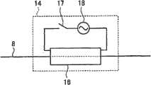
图4是示出图1的发送电路14的结构例的框图。在图4中,在发送电路14中设置有:以覆盖电力线8的方式配置的线圈16、将振幅周期性地变化的电流供给到线圈16的周期电源18、以及使流过线圈16的电流成为接通(ON)/断开(OFF)的发送开关17。另外,周期电源18可以改变供给到线圈16中的电流的频率,例如可以将频率为F1、F2的电流供给到线圈16。FIG. 4 is a block diagram showing a configuration example of the
并且,发送开关17在图2的时刻T1~T2以及时刻T3~T4成为接通,并且周期电源18可以在时刻T1~T2将电流的频率设定为F1,在时刻T3~T4将电流的频率设定为F2。And, the transmitting
并且,在时刻T1~T2,使发送开关17接通,从而使频率为F1的电流供给到线圈16,通过线圈16的电磁感应,使周期信号20重叠到电力线8。另外,在时刻T3~T4,使发送开关17接通,从而使频率为F2的电流供给到线圈16,通过线圈16的电磁感应,使周期信号21重叠到电力线8。Then, at times T1 to T2, the
另外,在图4的例子中,说明了为了使周期信号20、21重叠到电力线8而通过1个周期电源18产生频率为F1、F2的电流的方法,但也可以通过单独(separate)的周期电源18产生频率为F1、F2的电流。另外,发送电路14不限于通过电磁感应使周期信号20、21间接地重叠到电力线8的结构,也可以是使周期信号20、21直接重叠到电力线8的结构,例如,也可以在电力线8的中途设置周期性地通断的开关元件,或者经由开关元件将其他电源连接到电力线8。In addition, in the example of FIG. 4, in order to make the
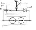
图5是示出图1的衰减电路4的第1结构例的框图。在图5中,在衰减电路4中设置有电容器30以及电阻器31。并且,电阻器31与旁路二极管5串联连接,并且电容器30连接到电阻器31的端子与接地之间,从而构成了低通滤波器。FIG. 5 is a block diagram showing a first configuration example of the
并且,如果将周期信号的频率设为5kHz、将电容器30的静电电容设为50μF、将电阻器31的电阻值设为5Ω,则通过下述关系式,可以将衰减电路4中的周期信号的衰减电压比设为输入电压的约1/8。And, if the frequency of the periodic signal is set to 5kHz, the capacitance of the
(衰减电压比)=1/(1+(2π×(频率)×(静电电容)×(电阻值))2)0.5(Attenuation voltage ratio)=1/(1+(2π×(frequency)×(capacitance)×(resistance value))2 )0.5
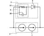
图6是示出图1的衰减电路4的第2结构例的框图。在图6中,在衰减电路4中设置有电容器36以及电阻器37。并且,电阻器37与旁路二极管5串联连接,并且电容器36与电阻器37并联连接,从而构成了低通滤波器。FIG. 6 is a block diagram showing a second configuration example of the
如以上说明,根据本实施例1的太阳光发电装置,通过在电力线8的中途设置发送电路14、接收电路15,并且在旁路电路3的中途设置简单的结构的衰减电路4,从而可以实现太阳光发电装置的故障检测。因此,故障检测部的配置变得自由,设置也变得容易,并且可以廉价且容易地实现故障检测,而且,可以将周期信号总是可靠地重叠到电力线8中,可以稳定且可靠地检测向旁路电路3的直流电力的通电动作。As described above, according to the photovoltaic power generation device of the first embodiment, by providing the transmitting
另外,在一定时间以上连续探测到由接收电路15接收到的周期信号的振幅从规定振幅衰减了一定以上时判定为对旁路电路3通电了直流电力,从而可以抑制瞬间的噪声等所致的误判定,可以提高向旁路电路3的直流电力的通电动作的判定精度。In addition, when it is continuously detected that the amplitude of the periodic signal received by the receiving
另外,定期或者临时使发送电路14在一定时间内发送周期信号、并在该期间由接收电路15接收到的周期信号的振幅从规定振幅衰减了一定以上时判定为对旁路电路3通电了直流电力,从而可以抑制周期信号的生成所需的功耗。In addition, when the transmitting
另外,通过使多个频率的周期信号重叠到电力线8中,并且使与这些周期信号的频率对应的衰减电路4的衰减频带针对每个旁路电路3不同,从而可以容易地确定直流电力进行了通电动作的旁路电路3,可以容易地确定产生了故障的太阳能电池模块6。In addition, by superimposing periodic signals of a plurality of frequencies on the
另外,通过将多个频率的周期信号在时间上分离地重叠到电力线8,从而与同时重叠了多个频率的情况相比,可以容易进行周期信号的分离、识别,可以提高向旁路电路3的直流电力的通电动作的判定精度,并且可以更容易地确定直流电力进行了通电动作的旁路电路3。In addition, by superimposing periodic signals of a plurality of frequencies on the
另外,在所述实施例1中,说明了作为衰减电路4而使用低通滤波器的方法,但是如使小于一定频率的周期信号进行衰减的高通滤波器、仅使一定范围的频率的周期信号通过的带通滤波器等,只要能够使周期信号衰减,就可以使用任意的衰减电路。In addition, in the above-mentioned first embodiment, the method of using a low-pass filter as the
另外,在所述实施例1中,说明了在时间上分离地使多个频率的周期信号重叠到电力线8中的方法,但也可以不在时间上分离多个频率的周期信号,而将复用了多个频率的周期信号重叠到电力线8中。由此,可以缩短向旁路电路3的直流电力的通电动作的判定时间,而且能够在同一时刻进行判定,不容易受到日照等条件的变动,所以可以提高判别精度。In addition, in the above-mentioned first embodiment, the method of superimposing periodic signals of a plurality of frequencies on the
另外,在所述实施例1中,说明了作为周期信号使用正弦波状的信号的方法,但周期信号不限于正弦波状的信号,也可以是三角波、矩形波。另外,周期信号也可以不是从中心电压上下均匀地进行振幅的波,而是朝向上或者下的一方进行振幅的半波。In addition, in the first embodiment, a method of using a sinusoidal signal as a periodic signal was described, but the periodic signal is not limited to a sinusoidal signal, and may be a triangular wave or a rectangular wave. In addition, the periodic signal may not be a wave whose amplitude is uniform up and down from the center voltage, but may be a half-wave whose amplitude is either upward or downward.
另外,在所述实施例1中,说明了将发送电路14、接收电路15始终附设到电力线8中的方法,但也可以仅在重叠或者接收周期信号时将发送电路14、接收电路15临时附设到电力线8中。例如,也可以仅在太阳光发电装置的检查运转时将发送电路14、接收电路15临时附设到电力线8中。In addition, in the above-mentioned first embodiment, the method of always attaching the transmitting
实施例2Example 2
图7是示出本发明的太阳光发电装置的实施例2的概要结构的框图。在图7中,在该太阳光发电装置中,除了图1的太阳光发电装置的结构以外,还设置有衰减电路32A、32B。另外,作为衰减电路32A、32B,可以使用仅使一定范围的频率的周期信号通过的带通滤波器。此处,衰减电路32A连接到向太阳能电池串7A的电流流入侧的电力线8A上,衰减电路32B连接到向太阳能电池串7B的电流流入侧的电力线8B上。并且,可以使在衰减电路32A、32B之间能够通过的周期信号的频带不同,衰减电路32A可以仅使由太阳能电池串7A侧的衰减电路4衰减的周期信号的频带通过,衰减电路32B可以仅使由太阳能电池串7B侧的衰减电路4衰减的周期信号的频带通过。Fig. 7 is a block diagram showing a schematic configuration of
例如,图2的频率为F1、F2的周期信号20、21从发送电路14送出到电力线8,太阳能电池串7A侧的衰减电路4以使频率为F1的周期信号衰减的方式设定了衰减特性,太阳能电池串7B侧的衰减电路4以使频率为F2的周期信号衰减的方式设定了衰减特性。在该情况下,在衰减电路32A中,可以以使频率为F1的周期信号尽可能不衰减而使频率为F2的周期信号衰减的方式设定衰减特性,在衰减电路32B中,可以以使频率为F2的周期信号尽可能不衰减而使频率为F1的周期信号衰减的方式设定衰减特性。For example, the
另外,优选使由在太阳能电池串7A、7B中分别包含多个的衰减电路4衰减的周期信号的频率范围不重复而完全分离。In addition, it is preferable that the frequency ranges of the periodic signals attenuated by the
并且,如果具有图2的频率F1、F2的周期信号20、21从发送电路14送出到电力线8上,则在衰减电路32A中,频率为F2的周期信号21衰减,频率为F1的周期信号20主要经由电力线8A而输入到太阳能电池串7A,并且在衰减电路32B中,频率为F1的周期信号20衰减,频率为F2的周期信号21主要经由电力线8B而输入到太阳能电池串7B。And, if the
并且,在太阳能电池串7A、7B中的任意一个的太阳能电池单元1中都没有故障的情况下,输入到太阳能电池串7A的周期信号20不通过衰减电路4,而通过太阳能电池串7A,经由电力线8输入到接收电路15,并且输入到太阳能电池串7B的周期信号21不通过衰减电路4,而通过太阳能电池串7B,经由电力线8输入到接收电路15。并且,在接收电路15中,如果从发送电路14送出的周期信号20、21的衰减量除去由衰减电路32A、32B所致的衰减部分而被探测到大致为0,则判定电路19判定为对太阳能电池串7A、7B中的任意一个的旁路电路3都没有通电直流电力,判断为在太阳能电池串7A、7B中的任意一个的太阳能电池模块6中都没有无法恢复的故障。In addition, when there is no failure in the
另一方面,在太阳能电池串7A中的某一个太阳能电池模块6的太阳能电池单元1中产生了断线等故障的情况下,与由该太阳能电池单元1构成的连接单位2并联连接的旁路电路3内的衰减电路4导通。因此,通过了衰减电路32A的频率为F1的周期信号20经由与由产生了故障的太阳能电池单元1构成的连接单位2并联连接的旁路电路3内的衰减电路4而到达接收电路15。On the other hand, when a fault such as disconnection occurs in the
另一方面,在太阳能电池串7B侧的电力线8B中,频率为F1的周期信号20通过衰减电路32B被衰减,所以可以几乎忽略经由太阳能电池串7B侧的电力线8B而到达接收电路15的频率为F1的周期信号20。On the other hand, in the
因此,在接收电路15中,通过了衰减电路32A的频率为F1的周期信号20被探测为其衰减量超过规定值。并且,在探测到频率为F1的周期信号20的衰减量超过规定值的情况下,判定电路19判定为对太阳能电池串7A中的某一个旁路电路3通电了直流电力,判断为在太阳能电池串7A中的某一个太阳能电池模块6中存在无法恢复的故障。Therefore, in the receiving
另外,在太阳能电池串7B中的某一个太阳能电池模块6的太阳能电池单元1中产生了断线等故障的情况下,与由该太阳能电池单元1构成的连接单位2并联连接的旁路电路3内的衰减电路4导通。因此,通过了衰减电路32B的频率为F2的周期信号21,经由与由产生了故障的太阳能电池单元1构成的连接单位2并联连接的旁路电路3内的衰减电路4而到达接收电路15。In addition, when a failure such as disconnection occurs in the
另一方面,在太阳能电池串7A侧的电力线8A中,频率为F2的周期信号21通过衰减电路32A而衰减,所以可以几乎忽略经由太阳能电池串7A侧的电力线8A而到达接收电路15的频率为F2的周期信号21。On the other hand, in the
因此,在接收电路15中,通过了衰减电路32B的频率为F2的周期信号21被探测为其衰减量超过规定值。并且,在探测到频率为F2的周期信号21的衰减量超过规定值的情况下,判定电路19判定为对太阳能电池串7B中的某一个旁路电路3通电了直流电力,判断为在太阳能电池串7B中的某一个太阳能电池模块6中存在无法恢复的故障。Therefore, in the receiving
由此,在对太阳能电池串7A、7B共同地设置了发送电路14的情况下,也可以使分别输入到太阳能电池串7A、7B中的周期信号的频带相互不同,可以减少分别通过了太阳能电池串7A、7B的同一频带的周期信号在接收电路15中混合的情形。因此,例如在太阳能电池串7A中包含的包括衰减电路4的旁路电路3进行了通电动作时可以进一步增大可由接收电路15探测的周期信号20的衰减率,可以针对太阳能电池串7A、7B的每一个,分离地判定向旁路电路3的直流电力的通电动作,所以特别是在并联连接了多个太阳能电池串时,可以提高故障检测的判定精度。Thus, even when the transmitting
实施例3Example 3
图8是示出本发明的太阳光发电装置的实施例3中应用的旁路电力线9A的结构例的框图。在图8中,在衰减电路32A的输入侧以及输出侧,分别设置有在电力线8A上对衰减电路32A进行旁路的切换开关34、35以及旁路电力线9A。另外,对于衰减电路32B也可以设置同样的结构。FIG. 8 is a block diagram showing a configuration example of a bypass
并且,在向太阳能电池串7A、7B送出周期信号20、21的情况下,通过将切换开关34、35切换到衰减电路32A、32B侧,可以使衰减电路32A、32B临时通电。In addition, when
由此,可以仅在检查太阳能电池单元1的故障时,使衰减电路32A、32B通电,可以防止衰减电路32A、32B始终被通电,所以可以抑制通电损失,并且可以防止电路的劣化。Thereby, the
另外,对于图7的发送电路14、接收电路15,也可以分别设置使发送电路14以及接收电路15在电力线8上进行旁路的切换开关以及旁路电力线,在向太阳能电池串7A、7B送出周期信号20、21的情况下,向发送电路14以及接收电路15侧切换切换开关,由此使发送电路14以及接收电路15临时通电。In addition, for the transmitting
实施例4Example 4
图9是示出本发明的太阳光发电装置的实施例4的概要结构的框图。在图9中,在该太阳光发电装置中,除了图1的太阳光发电装置的结构以外,还设置有进行开闭器33A、33B以及开闭器33A、33B的开闭控制的控制电路41。另外,作为开闭器33A、33B,既可以使用机械开关,也可以使用晶体管等电子开关元件。此处,开闭器33A连接到向太阳能电池串7A的电流流入侧的电力线8A上,开闭器33B连接到向太阳能电池串7B的电流流入侧的电力线8B上。另外,也可以设为开闭器33A连接到向太阳能电池串7A的电流流出侧的电力线8A上,开闭器33B连接到向太阳能电池串7B的电流流出侧的电力线8B上。Fig. 9 is a block diagram showing a schematic configuration of
另外,在设置了开闭器33A、33B的情况下,也可以使从发送电路14送出的周期信号仅具有单一的频率分量,另外也可以在太阳能电池串7A、7B之间,使用衰减特性相同的衰减电路4。例如,可以使周期信号具有图2的F1这样的频率之后,以使频率为F1的周期信号衰减的方式,共同地设定太阳能电池串7A、7B的衰减电路4的衰减特性。In addition, when the switches 33A and 33B are provided, the periodic signal sent from the
另外,在设置了开闭器33A、33B的情况下,从发送电路14送出的发送信号未必限定于周期信号,也可以是单一或者多个非周期性的脉冲信号等。在该情况下,衰减电路4可以由使脉冲信号衰减的低通滤波器等构成。In addition, when the switches 33A and 33B are provided, the transmission signal sent from the
另外,在处于通常的发电状态的情况下,控制电路41使开闭器33A、33B全部闭合,使电力线8A、8B成为导通状态。另一方面,在判定太阳能电池串7A、7B的旁路电路3的通电动作的情况下,控制电路41仅使在电力线8A、8B上分别设置的某1个开闭器33A、33B闭合,从而仅使某1个电力线8A、8B成为导通状态。In addition, in the normal power generation state, the control circuit 41 closes all the switches 33A, 33B, and brings the
例如,在判定太阳能电池串7A的旁路电路3的通电动作的情况下,控制电路41使开闭器33A闭合,使开闭器33B开启。For example, when determining the energization operation of the
并且,如果图2的具有频率F1的周期信号20从发送电路14送出到电力线8上,则周期信号20经由开闭器33A而输入到太阳能电池串7A。Then, when the
另外,在太阳能电池串7A中的任意一个太阳能电池单元1中都没有故障的情况下,输入到太阳能电池串7A的周期信号20不通过衰减电路4,而通过太阳能电池串7A,并经由电力线8而输入到接收电路15。并且,在接收电路15中,如果探测到从发送电路14送出的周期信号20的衰减量大致为0,则判定电路19判定为对太阳能电池串7A中的任意一个旁路电路3都没有通电直流电力,判断为在太阳能电池串7A中的任意一个太阳能电池模块6中都没有无法恢复的故障。In addition, when there is no failure in any one of the
另一方面,在太阳能电池串7A中的某一个太阳能电池单元1中产生了故障的情况下,与由该太阳能电池单元1构成的连接单位2并联连接的旁路电路3内的衰减电路4导通。因此,从发送电路14送出的频率为F1的周期信号20经由与由产生了故障的太阳能电池单元1构成的连接单位2并联连接的旁路电路3内的衰减电路4而到达接收电路15。On the other hand, when a failure occurs in one of the
并且,如果经由了衰减电路4的频率为F1的周期信号20到达接收电路15,则在接收电路15中,探测到频率为F1的周期信号20的衰减量超过规定值。并且,在探测到频率为F1的周期信号20的衰减量超过规定值的情况下,判定电路19判定为对太阳能电池串7A中的某一个旁路电路3通电了直流电力,判断为在太阳能电池串7A中的某一个太阳能电池模块6中存在无法恢复的故障。Then, when the
此处,在判定太阳能电池串7A的旁路电路3的通电动作的情况下,开闭器33B被开启,所以可以防止频率为F1的周期信号20经由太阳能电池串7B侧的电力线8B而到达接收电路15。因此,即使在对太阳能电池串7A、7B共同地设置了发送电路14以及接收电路15的情况下,也可以减少分别通过了太阳能电池串7A、7B的频率为F1的周期信号20在接收电路15中被混合的情形,可以针对太阳能电池串7A、7B的每一个,分离地进行向旁路电路3的直流电力的通电动作的判定,所以可以提高故障检测的判定精度。另外,由于无需针对太阳能电池串7A、7B的每一个改变周期信号的频率,所以可以更廉价地构成。Here, when determining the energization operation of the
另外,在判定太阳能电池串7B的旁路电路3的通电动作的情况下,控制电路41使开闭器33A开启,使开闭器33B闭合。In addition, when determining the energization operation of the
并且,如果图2的具有频率F1的周期信号20从发送电路14送出到电力线8上,则周期信号20经由开闭器33B而输入到太阳能电池串7B。Then, when the
并且,在太阳能电池串7B中的任意一个太阳能电池单元1中都没有故障的情况下,输入到太阳能电池串7B的周期信号20不通过衰减电路4,而通过太阳能电池串7B,并经由电力线8而输入到接收电路15。并且,在接收电路15中,如果探测到从发送电路14送出的周期信号20的衰减量大致为0,则判定电路19判定为对太阳能电池串7B中的任意一个旁路电路3都没有通电直流电力,判断为在太阳能电池串7B中的任意一个太阳能电池模块6中都没有无法恢复的故障。And, when there is no failure in any one of the
另一方面,在太阳能电池串7B中的某一个太阳能电池单元1中产生了故障的情况下,与由该太阳能电池单元1构成的连接单位2并联连接的旁路电路3内的衰减电路4导通。因此,从发送电路14送出的频率为F1的周期信号20,经由与由产生了故障的太阳能电池单元1构成的连接单位2并联连接的旁路电路3内的衰减电路4而到达接收电路15。On the other hand, when a failure occurs in one of the
并且,如果经由了衰减电路4的频率为F1的周期信号20到达接收电路15,则在接收电路15中探测到频率为F1的周期信号20的衰减量超过规定值。并且,在探测到频率为F1的周期信号20的衰减量超过规定值的情况下,判定电路19判定为对太阳能电池串7B中的某一个旁路电路3通电了直流电力,判断为在太阳能电池串7B中的某一个太阳能电池模块6中存在无法恢复的故障。Then, when the
此处,在判定太阳能电池串7B的旁路电路3的通电动作的情况下,开闭器33A被开启,所以可以防止频率为F1的周期信号20经由太阳能电池串7A侧的电力线8A而到达接收电路15,可以提高故障检测的判定精度。Here, when determining the energization operation of the
另外,在所述实施例4中,在使周期信号具有F1这样的1种频率之后,以使频率为F1的周期信号衰减的方式设定了太阳能电池串7A、7B的衰减电路4的衰减特性的情况为例子而进行了说明,但在各太阳能电池串7A、7B中有M个太阳能电池模块的情况下,也可以使周期信号具有F1~FM这样的M种频率之后,以使频率为F1~FM的周期信号分别衰减的方式设定各太阳能电池串7A、7B的M个太阳能电池模块的衰减电路4的衰减特性。In addition, in the fourth embodiment, the attenuation characteristics of the
另外,在所述实施例1~4中,将连接单位2内的太阳能电池单元1、太阳能电池模块6内的连接单位2、太阳光发电装置内的太阳能电池串7A、7B分别设为2个而进行了说明,但不限于该个数,也可以是1个或者3个以上。另外,在所述实施例中,将太阳能电池串7A、7B内的太阳能电池模块6设为3个以上,但也可以是1个或者2个。In addition, in the above-mentioned Examples 1 to 4, the
产业上的可利用性Industrial availability
如上所述,本发明的太阳光发电装置适用于对构成为可以通过经由旁路电路而对异常的太阳能电池单元进行旁路的太阳能电池模块的故障进行探测的方法。As described above, the photovoltaic power generation device of the present invention is suitable for a method of detecting a failure of a solar cell module configured to bypass an abnormal solar cell through a bypass circuit.
Claims (8)
Translated fromChineseApplications Claiming Priority (1)
| Application Number | Priority Date | Filing Date | Title |
|---|---|---|---|
| PCT/JP2008/062349WO2010004622A1 (en) | 2008-07-08 | 2008-07-08 | Solar power generation device |
Publications (2)
| Publication Number | Publication Date |
|---|---|
| CN102089883Atrue CN102089883A (en) | 2011-06-08 |
| CN102089883B CN102089883B (en) | 2013-02-06 |
Family
ID=41506756
Family Applications (1)
| Application Number | Title | Priority Date | Filing Date |
|---|---|---|---|
| CN2008801302514AExpired - Fee RelatedCN102089883B (en) | 2008-07-08 | 2008-07-08 | solar power plant |
Country Status (5)
| Country | Link |
|---|---|
| US (1) | US9184312B2 (en) |
| EP (1) | EP2299497A4 (en) |
| JP (1) | JP5073058B2 (en) |
| CN (1) | CN102089883B (en) |
| WO (1) | WO2010004622A1 (en) |
Cited By (51)
| Publication number | Priority date | Publication date | Assignee | Title |
|---|---|---|---|---|
| CN102867870A (en)* | 2011-07-04 | 2013-01-09 | 日立电线株式会社 | Solar photovoltaic junction box |
| CN103227588A (en)* | 2012-01-30 | 2013-07-31 | 太阳能安吉科技有限公司 | Photovoltaic panel circuit |
| US9362743B2 (en) | 2008-05-05 | 2016-06-07 | Solaredge Technologies Ltd. | Direct current power combiner |
| US9368964B2 (en) | 2006-12-06 | 2016-06-14 | Solaredge Technologies Ltd. | Distributed power system using direct current power sources |
| US9401599B2 (en) | 2010-12-09 | 2016-07-26 | Solaredge Technologies Ltd. | Disconnection of a string carrying direct current power |
| US9407161B2 (en) | 2007-12-05 | 2016-08-02 | Solaredge Technologies Ltd. | Parallel connected inverters |
| US9537445B2 (en) | 2008-12-04 | 2017-01-03 | Solaredge Technologies Ltd. | Testing of a photovoltaic panel |
| US9543889B2 (en) | 2006-12-06 | 2017-01-10 | Solaredge Technologies Ltd. | Distributed power harvesting systems using DC power sources |
| US9548619B2 (en) | 2013-03-14 | 2017-01-17 | Solaredge Technologies Ltd. | Method and apparatus for storing and depleting energy |
| US9590526B2 (en) | 2006-12-06 | 2017-03-07 | Solaredge Technologies Ltd. | Safety mechanisms, wake up and shutdown methods in distributed power installations |
| US9639106B2 (en) | 2012-03-05 | 2017-05-02 | Solaredge Technologies Ltd. | Direct current link circuit |
| US9647442B2 (en) | 2010-11-09 | 2017-05-09 | Solaredge Technologies Ltd. | Arc detection and prevention in a power generation system |
| US9680304B2 (en) | 2006-12-06 | 2017-06-13 | Solaredge Technologies Ltd. | Method for distributed power harvesting using DC power sources |
| US9812984B2 (en) | 2012-01-30 | 2017-11-07 | Solaredge Technologies Ltd. | Maximizing power in a photovoltaic distributed power system |
| US9853565B2 (en) | 2012-01-30 | 2017-12-26 | Solaredge Technologies Ltd. | Maximized power in a photovoltaic distributed power system |
| US9853538B2 (en) | 2007-12-04 | 2017-12-26 | Solaredge Technologies Ltd. | Distributed power harvesting systems using DC power sources |
| US9866098B2 (en) | 2011-01-12 | 2018-01-09 | Solaredge Technologies Ltd. | Serially connected inverters |
| US9869701B2 (en) | 2009-05-26 | 2018-01-16 | Solaredge Technologies Ltd. | Theft detection and prevention in a power generation system |
| US9876430B2 (en) | 2008-03-24 | 2018-01-23 | Solaredge Technologies Ltd. | Zero voltage switching |
| US9948233B2 (en) | 2006-12-06 | 2018-04-17 | Solaredge Technologies Ltd. | Distributed power harvesting systems using DC power sources |
| US9960731B2 (en) | 2006-12-06 | 2018-05-01 | Solaredge Technologies Ltd. | Pairing of components in a direct current distributed power generation system |
| US9966766B2 (en) | 2006-12-06 | 2018-05-08 | Solaredge Technologies Ltd. | Battery power delivery module |
| US9979280B2 (en) | 2007-12-05 | 2018-05-22 | Solaredge Technologies Ltd. | Parallel connected inverters |
| US10061957B2 (en) | 2016-03-03 | 2018-08-28 | Solaredge Technologies Ltd. | Methods for mapping power generation installations |
| US10116217B2 (en) | 2007-08-06 | 2018-10-30 | Solaredge Technologies Ltd. | Digital average input current control in power converter |
| US10184965B2 (en) | 2006-12-06 | 2019-01-22 | Solaredge Technologies Ltd. | Monitoring of distributed power harvesting systems using DC power sources |
| US10230310B2 (en) | 2016-04-05 | 2019-03-12 | Solaredge Technologies Ltd | Safety switch for photovoltaic systems |
| US10396662B2 (en) | 2011-09-12 | 2019-08-27 | Solaredge Technologies Ltd | Direct current link circuit |
| US10599113B2 (en) | 2016-03-03 | 2020-03-24 | Solaredge Technologies Ltd. | Apparatus and method for determining an order of power devices in power generation systems |
| US10651647B2 (en) | 2013-03-15 | 2020-05-12 | Solaredge Technologies Ltd. | Bypass mechanism |
| US10673222B2 (en) | 2010-11-09 | 2020-06-02 | Solaredge Technologies Ltd. | Arc detection and prevention in a power generation system |
| US10673229B2 (en) | 2010-11-09 | 2020-06-02 | Solaredge Technologies Ltd. | Arc detection and prevention in a power generation system |
| US10931119B2 (en) | 2012-01-11 | 2021-02-23 | Solaredge Technologies Ltd. | Photovoltaic module |
| US11018623B2 (en) | 2016-04-05 | 2021-05-25 | Solaredge Technologies Ltd. | Safety switch for photovoltaic systems |
| US11031861B2 (en) | 2006-12-06 | 2021-06-08 | Solaredge Technologies Ltd. | System and method for protection during inverter shutdown in distributed power installations |
| US11081608B2 (en) | 2016-03-03 | 2021-08-03 | Solaredge Technologies Ltd. | Apparatus and method for determining an order of power devices in power generation systems |
| US11177768B2 (en) | 2012-06-04 | 2021-11-16 | Solaredge Technologies Ltd. | Integrated photovoltaic panel circuitry |
| US11177663B2 (en) | 2016-04-05 | 2021-11-16 | Solaredge Technologies Ltd. | Chain of power devices |
| US11264947B2 (en) | 2007-12-05 | 2022-03-01 | Solaredge Technologies Ltd. | Testing of a photovoltaic panel |
| US11296650B2 (en) | 2006-12-06 | 2022-04-05 | Solaredge Technologies Ltd. | System and method for protection during inverter shutdown in distributed power installations |
| US11309832B2 (en) | 2006-12-06 | 2022-04-19 | Solaredge Technologies Ltd. | Distributed power harvesting systems using DC power sources |
| US11569659B2 (en) | 2006-12-06 | 2023-01-31 | Solaredge Technologies Ltd. | Distributed power harvesting systems using DC power sources |
| US11569660B2 (en) | 2006-12-06 | 2023-01-31 | Solaredge Technologies Ltd. | Distributed power harvesting systems using DC power sources |
| US11687112B2 (en) | 2006-12-06 | 2023-06-27 | Solaredge Technologies Ltd. | Distributed power harvesting systems using DC power sources |
| US11728768B2 (en) | 2006-12-06 | 2023-08-15 | Solaredge Technologies Ltd. | Pairing of components in a direct current distributed power generation system |
| US11735910B2 (en) | 2006-12-06 | 2023-08-22 | Solaredge Technologies Ltd. | Distributed power system using direct current power sources |
| US11855231B2 (en) | 2006-12-06 | 2023-12-26 | Solaredge Technologies Ltd. | Distributed power harvesting systems using DC power sources |
| US11881814B2 (en) | 2005-12-05 | 2024-01-23 | Solaredge Technologies Ltd. | Testing of a photovoltaic panel |
| US11888387B2 (en) | 2006-12-06 | 2024-01-30 | Solaredge Technologies Ltd. | Safety mechanisms, wake up and shutdown methods in distributed power installations |
| US12057807B2 (en) | 2016-04-05 | 2024-08-06 | Solaredge Technologies Ltd. | Chain of power devices |
| US12418177B2 (en) | 2009-10-24 | 2025-09-16 | Solaredge Technologies Ltd. | Distributed power system using direct current power sources |
Families Citing this family (15)
| Publication number | Priority date | Publication date | Assignee | Title |
|---|---|---|---|---|
| JP4999879B2 (en)* | 2009-04-28 | 2012-08-15 | 三菱電機株式会社 | Defect detection method for photovoltaic power generation system and solar cell module |
| JP2012138518A (en)* | 2010-12-27 | 2012-07-19 | Sony Corp | Photovoltaic power generation module and inspection method |
| AT12793U1 (en)* | 2011-05-26 | 2012-11-15 | Austria Tech & System Tech | PHOTOVOLTAIC MODULE AND USE THEREOF |
| DE102011053524B4 (en)* | 2011-09-12 | 2015-05-28 | Sma Solar Technology Ag | Safety device for a photovoltaic system and method for operating a safety device for a photovoltaic system |
| US8933721B2 (en)* | 2011-10-27 | 2015-01-13 | Infineon Technologies Austria Ag | Power source arrangement and method of diagnosing a power source arrangement |
| US20150180408A1 (en)* | 2012-07-09 | 2015-06-25 | Dow Global Technologies Llc | Systems and methods for detecting discontinuities in a solar array circuit and terminating current flow therein |
| JP2014154674A (en) | 2013-02-07 | 2014-08-25 | Mitsubishi Electric Corp | Solar cell module and photovoltaic power generation system |
| CN103441163B (en)* | 2013-09-06 | 2016-08-17 | 友达光电股份有限公司 | solar panel |
| US10069306B2 (en)* | 2014-02-21 | 2018-09-04 | Solarlytics, Inc. | System and method for managing the power output of a photovoltaic cell |
| AU2015267158B2 (en)* | 2014-05-27 | 2020-08-06 | Sunpower Corporation | Photovoltaic system protection |
| KR101638148B1 (en)* | 2014-12-12 | 2016-07-08 | 현대오트론 주식회사 | Apparatus and method for providing power in battery management system |
| WO2020174657A1 (en)* | 2019-02-28 | 2020-09-03 | オムロン株式会社 | Solar power generation system |
| DE102019131354A1 (en)* | 2019-11-20 | 2021-05-20 | Hanwha Q Cells Gmbh | Solar module |
| JP7333924B2 (en)* | 2020-02-19 | 2023-08-28 | シャープ株式会社 | Sensors and electronics |
| CN111404480B (en) | 2020-03-17 | 2021-09-14 | 华为技术有限公司 | Photovoltaic system, grouping method of photovoltaic units, computing device and storage medium |
Family Cites Families (22)
| Publication number | Priority date | Publication date | Assignee | Title |
|---|---|---|---|---|
| JP3486197B2 (en) | 1992-10-09 | 2004-01-13 | シャープ株式会社 | Solar cell module and fault detection method thereof |
| DE9312710U1 (en) | 1993-08-25 | 1993-10-28 | Institut für Solare Energieversorgungstechnik (ISET) - Verein an der Gesamthochschule Kassel, 34119 Kassel | Modular diagnostic system for the detection and localization of faults in photovoltaic systems |
| JPH07177652A (en)* | 1993-12-17 | 1995-07-14 | Canon Inc | Photovoltaic system and protection method for photovoltaic system |
| JPH0897456A (en) | 1994-09-22 | 1996-04-12 | Nissin Electric Co Ltd | Solar cell generator |
| JP3165606B2 (en) | 1994-12-27 | 2001-05-14 | シャープ株式会社 | Interconnected solar power generation system with solar cell module abnormality check function |
| JPH09102622A (en) | 1995-10-03 | 1997-04-15 | Nissin Electric Co Ltd | Failure detector of solar cell module of solar power generation system |
| JPH11330521A (en)* | 1998-03-13 | 1999-11-30 | Canon Inc | Photovoltaic module, photovoltaic array, photovoltaic power generation device, method for identifying failure of photovoltaic module |
| JP2000059986A (en)* | 1998-04-08 | 2000-02-25 | Canon Inc | Solar cell module failure detection method and apparatus, and solar cell module |
| JP2000196127A (en)* | 1998-12-25 | 2000-07-14 | Honda Motor Co Ltd | Fault diagnosing device and fault diagnosing method for concentrating tracking power generation system |
| JP2000269531A (en)* | 1999-01-14 | 2000-09-29 | Canon Inc | Solar cell module, building material with solar cell module, solar cell module enclosure, and solar power generation device |
| JP2001068706A (en)* | 1999-08-25 | 2001-03-16 | Sanyo Electric Co Ltd | Solar cell equipment |
| JP3779191B2 (en) | 2001-07-13 | 2006-05-24 | 積水化学工業株式会社 | Connection confirmation method for solar cell parallel array |
| CN2540683Y (en)* | 2002-04-18 | 2003-03-19 | 上海太阳能科技有限公司 | Crystalline silicon solar cell module |
| US7082019B2 (en)* | 2002-11-04 | 2006-07-25 | The Boeing Company | Method and apparatus to protect solar cells from electrostatic discharge damage |
| JP2004221479A (en) | 2003-01-17 | 2004-08-05 | Kyocera Corp | Solar power generator |
| JP2005151662A (en)* | 2003-11-13 | 2005-06-09 | Sharp Corp | Inverter device and distributed power supply system |
| US20050139258A1 (en)* | 2003-12-29 | 2005-06-30 | Yung-Hsiang Liu | Solar cell array control device |
| US7193872B2 (en)* | 2005-01-28 | 2007-03-20 | Kasemsan Siri | Solar array inverter with maximum power tracking |
| KR101205279B1 (en)* | 2006-03-23 | 2012-11-27 | 엔페이즈 에너지, 인코포레이티드 | Method and apparatus for converting direct current to alternating current |
| US7825325B2 (en)* | 2006-09-27 | 2010-11-02 | Kennedy & Violich Architecture Ltd. | Portable lighting and power-generating system |
| ITPD20060382A1 (en)* | 2006-10-13 | 2008-04-14 | Elettronica Santerno S P A | SOLAR INVERTER AND SOLAR ENERGY CONVERSION PLANT IN ELECTRICITY |
| US7772716B2 (en)* | 2007-03-27 | 2010-08-10 | Newdoll Enterprises Llc | Distributed maximum power point tracking system, structure and process |
- 2008
- 2008-07-08EPEP08790986.7Apatent/EP2299497A4/ennot_activeWithdrawn
- 2008-07-08CNCN2008801302514Apatent/CN102089883B/ennot_activeExpired - Fee Related
- 2008-07-08JPJP2010519587Apatent/JP5073058B2/ennot_activeExpired - Fee Related
- 2008-07-08WOPCT/JP2008/062349patent/WO2010004622A1/enactiveApplication Filing
- 2008-07-08USUS13/002,724patent/US9184312B2/ennot_activeExpired - Fee Related
Cited By (137)
| Publication number | Priority date | Publication date | Assignee | Title |
|---|---|---|---|---|
| US11881814B2 (en) | 2005-12-05 | 2024-01-23 | Solaredge Technologies Ltd. | Testing of a photovoltaic panel |
| US11728768B2 (en) | 2006-12-06 | 2023-08-15 | Solaredge Technologies Ltd. | Pairing of components in a direct current distributed power generation system |
| US11183922B2 (en) | 2006-12-06 | 2021-11-23 | Solaredge Technologies Ltd. | Distributed power harvesting systems using DC power sources |
| US12316274B2 (en) | 2006-12-06 | 2025-05-27 | Solaredge Technologies Ltd. | Pairing of components in a direct current distributed power generation system |
| US12281919B2 (en) | 2006-12-06 | 2025-04-22 | Solaredge Technologies Ltd. | Monitoring of distributed power harvesting systems using DC power sources |
| US9368964B2 (en) | 2006-12-06 | 2016-06-14 | Solaredge Technologies Ltd. | Distributed power system using direct current power sources |
| US12276997B2 (en) | 2006-12-06 | 2025-04-15 | Solaredge Technologies Ltd. | Distributed power harvesting systems using DC power sources |
| US12224706B2 (en) | 2006-12-06 | 2025-02-11 | Solaredge Technologies Ltd. | Pairing of components in a direct current distributed power generation system |
| US12107417B2 (en) | 2006-12-06 | 2024-10-01 | Solaredge Technologies Ltd. | Distributed power harvesting systems using DC power sources |
| US9543889B2 (en) | 2006-12-06 | 2017-01-10 | Solaredge Technologies Ltd. | Distributed power harvesting systems using DC power sources |
| US12068599B2 (en) | 2006-12-06 | 2024-08-20 | Solaredge Technologies Ltd. | System and method for protection during inverter shutdown in distributed power installations |
| US9590526B2 (en) | 2006-12-06 | 2017-03-07 | Solaredge Technologies Ltd. | Safety mechanisms, wake up and shutdown methods in distributed power installations |
| US12046940B2 (en) | 2006-12-06 | 2024-07-23 | Solaredge Technologies Ltd. | Battery power control |
| US12032080B2 (en) | 2006-12-06 | 2024-07-09 | Solaredge Technologies Ltd. | Safety mechanisms, wake up and shutdown methods in distributed power installations |
| US9680304B2 (en) | 2006-12-06 | 2017-06-13 | Solaredge Technologies Ltd. | Method for distributed power harvesting using DC power sources |
| US12027970B2 (en) | 2006-12-06 | 2024-07-02 | Solaredge Technologies Ltd. | Safety mechanisms, wake up and shutdown methods in distributed power installations |
| US12027849B2 (en) | 2006-12-06 | 2024-07-02 | Solaredge Technologies Ltd. | Distributed power system using direct current power sources |
| US9853490B2 (en) | 2006-12-06 | 2017-12-26 | Solaredge Technologies Ltd. | Distributed power system using direct current power sources |
| US11962243B2 (en) | 2006-12-06 | 2024-04-16 | Solaredge Technologies Ltd. | Method for distributed power harvesting using DC power sources |
| US11961922B2 (en) | 2006-12-06 | 2024-04-16 | Solaredge Technologies Ltd. | Distributed power harvesting systems using DC power sources |
| US11888387B2 (en) | 2006-12-06 | 2024-01-30 | Solaredge Technologies Ltd. | Safety mechanisms, wake up and shutdown methods in distributed power installations |
| US11855231B2 (en) | 2006-12-06 | 2023-12-26 | Solaredge Technologies Ltd. | Distributed power harvesting systems using DC power sources |
| US10097007B2 (en) | 2006-12-06 | 2018-10-09 | Solaredge Technologies Ltd. | Method for distributed power harvesting using DC power sources |
| US9948233B2 (en) | 2006-12-06 | 2018-04-17 | Solaredge Technologies Ltd. | Distributed power harvesting systems using DC power sources |
| US9960731B2 (en) | 2006-12-06 | 2018-05-01 | Solaredge Technologies Ltd. | Pairing of components in a direct current distributed power generation system |
| US9966766B2 (en) | 2006-12-06 | 2018-05-08 | Solaredge Technologies Ltd. | Battery power delivery module |
| US11031861B2 (en) | 2006-12-06 | 2021-06-08 | Solaredge Technologies Ltd. | System and method for protection during inverter shutdown in distributed power installations |
| US12388492B2 (en) | 2006-12-06 | 2025-08-12 | Solaredge Technologies Ltd. | Safety mechanisms, wake up and shutdown methods in distributed power installations |
| US11687112B2 (en) | 2006-12-06 | 2023-06-27 | Solaredge Technologies Ltd. | Distributed power harvesting systems using DC power sources |
| US11735910B2 (en) | 2006-12-06 | 2023-08-22 | Solaredge Technologies Ltd. | Distributed power system using direct current power sources |
| US10184965B2 (en) | 2006-12-06 | 2019-01-22 | Solaredge Technologies Ltd. | Monitoring of distributed power harvesting systems using DC power sources |
| US10230245B2 (en) | 2006-12-06 | 2019-03-12 | Solaredge Technologies Ltd | Battery power delivery module |
| US11658482B2 (en) | 2006-12-06 | 2023-05-23 | Solaredge Technologies Ltd. | Distributed power harvesting systems using DC power sources |
| US11598652B2 (en) | 2006-12-06 | 2023-03-07 | Solaredge Technologies Ltd. | Monitoring of distributed power harvesting systems using DC power sources |
| US11594882B2 (en) | 2006-12-06 | 2023-02-28 | Solaredge Technologies Ltd. | Distributed power harvesting systems using DC power sources |
| US10447150B2 (en) | 2006-12-06 | 2019-10-15 | Solaredge Technologies Ltd. | Distributed power harvesting systems using DC power sources |
| US11594880B2 (en) | 2006-12-06 | 2023-02-28 | Solaredge Technologies Ltd. | Distributed power harvesting systems using DC power sources |
| US11594881B2 (en) | 2006-12-06 | 2023-02-28 | Solaredge Technologies Ltd. | Distributed power harvesting systems using DC power sources |
| US11575261B2 (en) | 2006-12-06 | 2023-02-07 | Solaredge Technologies Ltd. | Distributed power harvesting systems using DC power sources |
| US11043820B2 (en) | 2006-12-06 | 2021-06-22 | Solaredge Technologies Ltd. | Battery power delivery module |
| US11575260B2 (en) | 2006-12-06 | 2023-02-07 | Solaredge Technologies Ltd. | Distributed power harvesting systems using DC power sources |
| US10637393B2 (en) | 2006-12-06 | 2020-04-28 | Solaredge Technologies Ltd. | Distributed power harvesting systems using DC power sources |
| US11569660B2 (en) | 2006-12-06 | 2023-01-31 | Solaredge Technologies Ltd. | Distributed power harvesting systems using DC power sources |
| US11569659B2 (en) | 2006-12-06 | 2023-01-31 | Solaredge Technologies Ltd. | Distributed power harvesting systems using DC power sources |
| US11476799B2 (en) | 2006-12-06 | 2022-10-18 | Solaredge Technologies Ltd. | Distributed power harvesting systems using DC power sources |
| US11309832B2 (en) | 2006-12-06 | 2022-04-19 | Solaredge Technologies Ltd. | Distributed power harvesting systems using DC power sources |
| US11296650B2 (en) | 2006-12-06 | 2022-04-05 | Solaredge Technologies Ltd. | System and method for protection during inverter shutdown in distributed power installations |
| US10673253B2 (en) | 2006-12-06 | 2020-06-02 | Solaredge Technologies Ltd. | Battery power delivery module |
| US11682918B2 (en) | 2006-12-06 | 2023-06-20 | Solaredge Technologies Ltd. | Battery power delivery module |
| US11063440B2 (en) | 2006-12-06 | 2021-07-13 | Solaredge Technologies Ltd. | Method for distributed power harvesting using DC power sources |
| US10116217B2 (en) | 2007-08-06 | 2018-10-30 | Solaredge Technologies Ltd. | Digital average input current control in power converter |
| US11594968B2 (en) | 2007-08-06 | 2023-02-28 | Solaredge Technologies Ltd. | Digital average input current control in power converter |
| US10516336B2 (en) | 2007-08-06 | 2019-12-24 | Solaredge Technologies Ltd. | Digital average input current control in power converter |
| US9853538B2 (en) | 2007-12-04 | 2017-12-26 | Solaredge Technologies Ltd. | Distributed power harvesting systems using DC power sources |
| US11183923B2 (en) | 2007-12-05 | 2021-11-23 | Solaredge Technologies Ltd. | Parallel connected inverters |
| US11183969B2 (en) | 2007-12-05 | 2021-11-23 | Solaredge Technologies Ltd. | Testing of a photovoltaic panel |
| US10644589B2 (en) | 2007-12-05 | 2020-05-05 | Solaredge Technologies Ltd. | Parallel connected inverters |
| US11264947B2 (en) | 2007-12-05 | 2022-03-01 | Solaredge Technologies Ltd. | Testing of a photovoltaic panel |
| US11693080B2 (en) | 2007-12-05 | 2023-07-04 | Solaredge Technologies Ltd. | Parallel connected inverters |
| US9407161B2 (en) | 2007-12-05 | 2016-08-02 | Solaredge Technologies Ltd. | Parallel connected inverters |
| US9979280B2 (en) | 2007-12-05 | 2018-05-22 | Solaredge Technologies Ltd. | Parallel connected inverters |
| US10693415B2 (en) | 2007-12-05 | 2020-06-23 | Solaredge Technologies Ltd. | Testing of a photovoltaic panel |
| US12055647B2 (en) | 2007-12-05 | 2024-08-06 | Solaredge Technologies Ltd. | Parallel connected inverters |
| US11894806B2 (en) | 2007-12-05 | 2024-02-06 | Solaredge Technologies Ltd. | Testing of a photovoltaic panel |
| US9876430B2 (en) | 2008-03-24 | 2018-01-23 | Solaredge Technologies Ltd. | Zero voltage switching |
| US11424616B2 (en) | 2008-05-05 | 2022-08-23 | Solaredge Technologies Ltd. | Direct current power combiner |
| US12218498B2 (en) | 2008-05-05 | 2025-02-04 | Solaredge Technologies Ltd. | Direct current power combiner |
| US9362743B2 (en) | 2008-05-05 | 2016-06-07 | Solaredge Technologies Ltd. | Direct current power combiner |
| US10468878B2 (en) | 2008-05-05 | 2019-11-05 | Solaredge Technologies Ltd. | Direct current power combiner |
| US9537445B2 (en) | 2008-12-04 | 2017-01-03 | Solaredge Technologies Ltd. | Testing of a photovoltaic panel |
| US10461687B2 (en) | 2008-12-04 | 2019-10-29 | Solaredge Technologies Ltd. | Testing of a photovoltaic panel |
| US9869701B2 (en) | 2009-05-26 | 2018-01-16 | Solaredge Technologies Ltd. | Theft detection and prevention in a power generation system |
| US11867729B2 (en) | 2009-05-26 | 2024-01-09 | Solaredge Technologies Ltd. | Theft detection and prevention in a power generation system |
| US12306215B2 (en) | 2009-05-26 | 2025-05-20 | Solaredge Technologies Ltd. | Theft detection and prevention in a power generation system |
| US10969412B2 (en) | 2009-05-26 | 2021-04-06 | Solaredge Technologies Ltd. | Theft detection and prevention in a power generation system |
| US12418177B2 (en) | 2009-10-24 | 2025-09-16 | Solaredge Technologies Ltd. | Distributed power system using direct current power sources |
| US10673222B2 (en) | 2010-11-09 | 2020-06-02 | Solaredge Technologies Ltd. | Arc detection and prevention in a power generation system |
| US9647442B2 (en) | 2010-11-09 | 2017-05-09 | Solaredge Technologies Ltd. | Arc detection and prevention in a power generation system |
| US12003215B2 (en) | 2010-11-09 | 2024-06-04 | Solaredge Technologies Ltd. | Arc detection and prevention in a power generation system |
| US11489330B2 (en) | 2010-11-09 | 2022-11-01 | Solaredge Technologies Ltd. | Arc detection and prevention in a power generation system |
| US12407158B2 (en) | 2010-11-09 | 2025-09-02 | Solaredge Technologies Ltd. | Arc detection and prevention in a power generation system |
| US11070051B2 (en) | 2010-11-09 | 2021-07-20 | Solaredge Technologies Ltd. | Arc detection and prevention in a power generation system |
| US11349432B2 (en) | 2010-11-09 | 2022-05-31 | Solaredge Technologies Ltd. | Arc detection and prevention in a power generation system |
| US10931228B2 (en) | 2010-11-09 | 2021-02-23 | Solaredge Technologies Ftd. | Arc detection and prevention in a power generation system |
| US10673229B2 (en) | 2010-11-09 | 2020-06-02 | Solaredge Technologies Ltd. | Arc detection and prevention in a power generation system |
| US11271394B2 (en) | 2010-12-09 | 2022-03-08 | Solaredge Technologies Ltd. | Disconnection of a string carrying direct current power |
| US9935458B2 (en) | 2010-12-09 | 2018-04-03 | Solaredge Technologies Ltd. | Disconnection of a string carrying direct current power |
| US12295184B2 (en) | 2010-12-09 | 2025-05-06 | Solaredge Technologies Ltd. | Disconnection of a string carrying direct current power |
| US9401599B2 (en) | 2010-12-09 | 2016-07-26 | Solaredge Technologies Ltd. | Disconnection of a string carrying direct current power |
| US11996488B2 (en) | 2010-12-09 | 2024-05-28 | Solaredge Technologies Ltd. | Disconnection of a string carrying direct current power |
| US11205946B2 (en) | 2011-01-12 | 2021-12-21 | Solaredge Technologies Ltd. | Serially connected inverters |
| US9866098B2 (en) | 2011-01-12 | 2018-01-09 | Solaredge Technologies Ltd. | Serially connected inverters |
| US12218505B2 (en) | 2011-01-12 | 2025-02-04 | Solaredge Technologies Ltd. | Serially connected inverters |
| US10666125B2 (en) | 2011-01-12 | 2020-05-26 | Solaredge Technologies Ltd. | Serially connected inverters |
| CN102867870B (en)* | 2011-07-04 | 2016-03-16 | 日立金属株式会社 | Solar power generation uses junction box |
| CN102867870A (en)* | 2011-07-04 | 2013-01-09 | 日立电线株式会社 | Solar photovoltaic junction box |
| US10396662B2 (en) | 2011-09-12 | 2019-08-27 | Solaredge Technologies Ltd | Direct current link circuit |
| US11979037B2 (en) | 2012-01-11 | 2024-05-07 | Solaredge Technologies Ltd. | Photovoltaic module |
| US10931119B2 (en) | 2012-01-11 | 2021-02-23 | Solaredge Technologies Ltd. | Photovoltaic module |
| US12191668B2 (en) | 2012-01-30 | 2025-01-07 | Solaredge Technologies Ltd. | Maximizing power in a photovoltaic distributed power system |
| CN103227588B (en)* | 2012-01-30 | 2017-06-30 | 太阳能安吉科技有限公司 | Photovoltaic panel circuit |
| US11183968B2 (en) | 2012-01-30 | 2021-11-23 | Solaredge Technologies Ltd. | Photovoltaic panel circuitry |
| US10992238B2 (en) | 2012-01-30 | 2021-04-27 | Solaredge Technologies Ltd. | Maximizing power in a photovoltaic distributed power system |
| CN103227588A (en)* | 2012-01-30 | 2013-07-31 | 太阳能安吉科技有限公司 | Photovoltaic panel circuit |
| US11929620B2 (en) | 2012-01-30 | 2024-03-12 | Solaredge Technologies Ltd. | Maximizing power in a photovoltaic distributed power system |
| US9923516B2 (en) | 2012-01-30 | 2018-03-20 | Solaredge Technologies Ltd. | Photovoltaic panel circuitry |
| US9853565B2 (en) | 2012-01-30 | 2017-12-26 | Solaredge Technologies Ltd. | Maximized power in a photovoltaic distributed power system |
| US10608553B2 (en) | 2012-01-30 | 2020-03-31 | Solaredge Technologies Ltd. | Maximizing power in a photovoltaic distributed power system |
| US10381977B2 (en) | 2012-01-30 | 2019-08-13 | Solaredge Technologies Ltd | Photovoltaic panel circuitry |
| US11620885B2 (en) | 2012-01-30 | 2023-04-04 | Solaredge Technologies Ltd. | Photovoltaic panel circuitry |
| US12094306B2 (en) | 2012-01-30 | 2024-09-17 | Solaredge Technologies Ltd. | Photovoltaic panel circuitry |
| US9812984B2 (en) | 2012-01-30 | 2017-11-07 | Solaredge Technologies Ltd. | Maximizing power in a photovoltaic distributed power system |
| US10007288B2 (en) | 2012-03-05 | 2018-06-26 | Solaredge Technologies Ltd. | Direct current link circuit |
| US9639106B2 (en) | 2012-03-05 | 2017-05-02 | Solaredge Technologies Ltd. | Direct current link circuit |
| US12218628B2 (en) | 2012-06-04 | 2025-02-04 | Solaredge Technologies Ltd. | Integrated photovoltaic panel circuitry |
| US11177768B2 (en) | 2012-06-04 | 2021-11-16 | Solaredge Technologies Ltd. | Integrated photovoltaic panel circuitry |
| US10778025B2 (en) | 2013-03-14 | 2020-09-15 | Solaredge Technologies Ltd. | Method and apparatus for storing and depleting energy |
| US12255457B2 (en) | 2013-03-14 | 2025-03-18 | Solaredge Technologies Ltd. | Method and apparatus for storing and depleting energy |
| US9548619B2 (en) | 2013-03-14 | 2017-01-17 | Solaredge Technologies Ltd. | Method and apparatus for storing and depleting energy |
| US12003107B2 (en) | 2013-03-14 | 2024-06-04 | Solaredge Technologies Ltd. | Method and apparatus for storing and depleting energy |
| US11424617B2 (en) | 2013-03-15 | 2022-08-23 | Solaredge Technologies Ltd. | Bypass mechanism |
| US12132125B2 (en) | 2013-03-15 | 2024-10-29 | Solaredge Technologies Ltd. | Bypass mechanism |
| US10651647B2 (en) | 2013-03-15 | 2020-05-12 | Solaredge Technologies Ltd. | Bypass mechanism |
| US11824131B2 (en) | 2016-03-03 | 2023-11-21 | Solaredge Technologies Ltd. | Apparatus and method for determining an order of power devices in power generation systems |
| US11081608B2 (en) | 2016-03-03 | 2021-08-03 | Solaredge Technologies Ltd. | Apparatus and method for determining an order of power devices in power generation systems |
| US10061957B2 (en) | 2016-03-03 | 2018-08-28 | Solaredge Technologies Ltd. | Methods for mapping power generation installations |
| US12224365B2 (en) | 2016-03-03 | 2025-02-11 | Solaredge Technologies Ltd. | Apparatus and method for determining an order of power devices in power generation systems |
| US11538951B2 (en) | 2016-03-03 | 2022-12-27 | Solaredge Technologies Ltd. | Apparatus and method for determining an order of power devices in power generation systems |
| US10540530B2 (en) | 2016-03-03 | 2020-01-21 | Solaredge Technologies Ltd. | Methods for mapping power generation installations |
| US10599113B2 (en) | 2016-03-03 | 2020-03-24 | Solaredge Technologies Ltd. | Apparatus and method for determining an order of power devices in power generation systems |
| US11201476B2 (en) | 2016-04-05 | 2021-12-14 | Solaredge Technologies Ltd. | Photovoltaic power device and wiring |
| US11018623B2 (en) | 2016-04-05 | 2021-05-25 | Solaredge Technologies Ltd. | Safety switch for photovoltaic systems |
| US11870250B2 (en) | 2016-04-05 | 2024-01-09 | Solaredge Technologies Ltd. | Chain of power devices |
| US12348182B2 (en) | 2016-04-05 | 2025-07-01 | Solaredge Technologies Ltd. | Safety switch for photovoltaic systems |
| US10230310B2 (en) | 2016-04-05 | 2019-03-12 | Solaredge Technologies Ltd | Safety switch for photovoltaic systems |
| US12057807B2 (en) | 2016-04-05 | 2024-08-06 | Solaredge Technologies Ltd. | Chain of power devices |
| US11177663B2 (en) | 2016-04-05 | 2021-11-16 | Solaredge Technologies Ltd. | Chain of power devices |
Also Published As
| Publication number | Publication date |
|---|---|
| WO2010004622A1 (en) | 2010-01-14 |
| JPWO2010004622A1 (en) | 2011-12-22 |
| CN102089883B (en) | 2013-02-06 |
| US20110127839A1 (en) | 2011-06-02 |
| EP2299497A1 (en) | 2011-03-23 |
| JP5073058B2 (en) | 2012-11-14 |
| US9184312B2 (en) | 2015-11-10 |
| EP2299497A4 (en) | 2014-02-19 |
Similar Documents
| Publication | Publication Date | Title |
|---|---|---|
| CN102089883B (en) | solar power plant | |
| US12298791B2 (en) | System and method for arc detection and intervention in solar energy systems | |
| EP2092631B1 (en) | Removable component cartridge for increasing reliability in power harvesting systems | |
| US20080144294A1 (en) | Removal component cartridge for increasing reliability in power harvesting systems | |
| US8461716B2 (en) | Photovoltaic power generating device, and controlling method | |
| US10672918B2 (en) | Photovoltaic panel rapid shutdown and recovery | |
| CN101939660B (en) | Methods for identifying photovoltaic module theft and failure of photovoltaic module bypass diodes, corresponding photovoltaic sub-generator junction boxes, photovoltaic inverters and corresponding photovoltaic equipment | |
| US8466789B2 (en) | Method for theft recognition on a photovoltaic unit and inverter for a photovoltaic unit | |
| US8659858B2 (en) | Ground-fault detecting device, current collecting box using the ground-fault detecting device, and photovoltaic power generating device using the current collecting box | |
| US20120050924A1 (en) | Current collecting box for photovoltaic power generation | |
| WO2013001820A1 (en) | System connection inverter device and control method therefor | |
| WO2012026447A1 (en) | Collector box for photovoltaic power generation | |
| CN102867870A (en) | Solar photovoltaic junction box | |
| KR20120126079A (en) | System for managing and controlling photovoltaic panels | |
| US20130207474A1 (en) | Matrix connection device for photovoltaic panels and/or wind turbines | |
| JP2001068706A (en) | Solar cell equipment | |
| KR101380366B1 (en) | System for monitoring photovoltaic power generation using power line communication | |
| WO2018148683A1 (en) | Portable renewable energy power converter/inverter and storage supply systems and methods | |
| CN201846251U (en) | Solar power generation device | |
| EP2267466A1 (en) | Apparatus for measuring the voltage and current generated by photovoltaic panels | |
| JP2011129702A (en) | Photovoltaic power generation device and photovoltaic power generation system |
Legal Events
| Date | Code | Title | Description |
|---|---|---|---|
| C06 | Publication | ||
| PB01 | Publication | ||
| C10 | Entry into substantive examination | ||
| SE01 | Entry into force of request for substantive examination | ||
| C14 | Grant of patent or utility model | ||
| GR01 | Patent grant | ||
| CF01 | Termination of patent right due to non-payment of annual fee | Granted publication date:20130206 Termination date:20190708 | |
| CF01 | Termination of patent right due to non-payment of annual fee |