CN102089023A - Injection Set with Magnetic Injection Complete Indicator and Needle Sheath Removal - Google Patents
Injection Set with Magnetic Injection Complete Indicator and Needle Sheath RemovalDownload PDFInfo
- Publication number
- CN102089023A CN102089023ACN2009801185197ACN200980118519ACN102089023ACN 102089023 ACN102089023 ACN 102089023ACN 2009801185197 ACN2009801185197 ACN 2009801185197ACN 200980118519 ACN200980118519 ACN 200980118519ACN 102089023 ACN102089023 ACN 102089023A
- Authority
- CN
- China
- Prior art keywords
- injection device
- injection
- housing
- syringe
- cooperating
- Prior art date
- Legal status (The legal status is an assumption and is not a legal conclusion. Google has not performed a legal analysis and makes no representation as to the accuracy of the status listed.)
- Granted
Links
Images


Classifications
- A—HUMAN NECESSITIES
- A61—MEDICAL OR VETERINARY SCIENCE; HYGIENE
- A61M—DEVICES FOR INTRODUCING MEDIA INTO, OR ONTO, THE BODY; DEVICES FOR TRANSDUCING BODY MEDIA OR FOR TAKING MEDIA FROM THE BODY; DEVICES FOR PRODUCING OR ENDING SLEEP OR STUPOR
- A61M5/00—Devices for bringing media into the body in a subcutaneous, intra-vascular or intramuscular way; Accessories therefor, e.g. filling or cleaning devices, arm-rests
- A61M5/178—Syringes
- A61M5/20—Automatic syringes, e.g. with automatically actuated piston rod, with automatic needle injection, filling automatically
- A61M5/2033—Spring-loaded one-shot injectors with or without automatic needle insertion
- A—HUMAN NECESSITIES
- A61—MEDICAL OR VETERINARY SCIENCE; HYGIENE
- A61M—DEVICES FOR INTRODUCING MEDIA INTO, OR ONTO, THE BODY; DEVICES FOR TRANSDUCING BODY MEDIA OR FOR TAKING MEDIA FROM THE BODY; DEVICES FOR PRODUCING OR ENDING SLEEP OR STUPOR
- A61M5/00—Devices for bringing media into the body in a subcutaneous, intra-vascular or intramuscular way; Accessories therefor, e.g. filling or cleaning devices, arm-rests
- A61M5/178—Syringes
- A61M5/31—Details
- A61M5/32—Needles; Details of needles pertaining to their connection with syringe or hub; Accessories for bringing the needle into, or holding the needle on, the body; Devices for protection of needles
- A61M5/3202—Devices for protection of the needle before use, e.g. caps
- A—HUMAN NECESSITIES
- A61—MEDICAL OR VETERINARY SCIENCE; HYGIENE
- A61M—DEVICES FOR INTRODUCING MEDIA INTO, OR ONTO, THE BODY; DEVICES FOR TRANSDUCING BODY MEDIA OR FOR TAKING MEDIA FROM THE BODY; DEVICES FOR PRODUCING OR ENDING SLEEP OR STUPOR
- A61M5/00—Devices for bringing media into the body in a subcutaneous, intra-vascular or intramuscular way; Accessories therefor, e.g. filling or cleaning devices, arm-rests
- A61M5/178—Syringes
- A61M5/24—Ampoule syringes, i.e. syringes with needle for use in combination with replaceable ampoules or carpules, e.g. automatic
- A61M2005/2403—Ampoule inserted into the ampoule holder
- A61M2005/2407—Ampoule inserted into the ampoule holder from the rear
- A—HUMAN NECESSITIES
- A61—MEDICAL OR VETERINARY SCIENCE; HYGIENE
- A61M—DEVICES FOR INTRODUCING MEDIA INTO, OR ONTO, THE BODY; DEVICES FOR TRANSDUCING BODY MEDIA OR FOR TAKING MEDIA FROM THE BODY; DEVICES FOR PRODUCING OR ENDING SLEEP OR STUPOR
- A61M5/00—Devices for bringing media into the body in a subcutaneous, intra-vascular or intramuscular way; Accessories therefor, e.g. filling or cleaning devices, arm-rests
- A61M5/178—Syringes
- A61M5/24—Ampoule syringes, i.e. syringes with needle for use in combination with replaceable ampoules or carpules, e.g. automatic
- A61M2005/2485—Ampoule holder connected to rest of syringe
- A61M2005/2488—Ampoule holder connected to rest of syringe via rotation, e.g. threads or bayonet
- A—HUMAN NECESSITIES
- A61—MEDICAL OR VETERINARY SCIENCE; HYGIENE
- A61M—DEVICES FOR INTRODUCING MEDIA INTO, OR ONTO, THE BODY; DEVICES FOR TRANSDUCING BODY MEDIA OR FOR TAKING MEDIA FROM THE BODY; DEVICES FOR PRODUCING OR ENDING SLEEP OR STUPOR
- A61M2205/00—General characteristics of the apparatus
- A61M2205/58—Means for facilitating use, e.g. by people with impaired vision
- A61M2205/581—Means for facilitating use, e.g. by people with impaired vision by audible feedback
- A—HUMAN NECESSITIES
- A61—MEDICAL OR VETERINARY SCIENCE; HYGIENE
- A61M—DEVICES FOR INTRODUCING MEDIA INTO, OR ONTO, THE BODY; DEVICES FOR TRANSDUCING BODY MEDIA OR FOR TAKING MEDIA FROM THE BODY; DEVICES FOR PRODUCING OR ENDING SLEEP OR STUPOR
- A61M2205/00—General characteristics of the apparatus
- A61M2205/58—Means for facilitating use, e.g. by people with impaired vision
- A61M2205/582—Means for facilitating use, e.g. by people with impaired vision by tactile feedback
- A—HUMAN NECESSITIES
- A61—MEDICAL OR VETERINARY SCIENCE; HYGIENE
- A61M—DEVICES FOR INTRODUCING MEDIA INTO, OR ONTO, THE BODY; DEVICES FOR TRANSDUCING BODY MEDIA OR FOR TAKING MEDIA FROM THE BODY; DEVICES FOR PRODUCING OR ENDING SLEEP OR STUPOR
- A61M2205/00—General characteristics of the apparatus
- A61M2205/58—Means for facilitating use, e.g. by people with impaired vision
- A61M2205/583—Means for facilitating use, e.g. by people with impaired vision by visual feedback
- A—HUMAN NECESSITIES
- A61—MEDICAL OR VETERINARY SCIENCE; HYGIENE
- A61M—DEVICES FOR INTRODUCING MEDIA INTO, OR ONTO, THE BODY; DEVICES FOR TRANSDUCING BODY MEDIA OR FOR TAKING MEDIA FROM THE BODY; DEVICES FOR PRODUCING OR ENDING SLEEP OR STUPOR
- A61M5/00—Devices for bringing media into the body in a subcutaneous, intra-vascular or intramuscular way; Accessories therefor, e.g. filling or cleaning devices, arm-rests
- A61M5/178—Syringes
- A61M5/24—Ampoule syringes, i.e. syringes with needle for use in combination with replaceable ampoules or carpules, e.g. automatic
- A—HUMAN NECESSITIES
- A61—MEDICAL OR VETERINARY SCIENCE; HYGIENE
- A61M—DEVICES FOR INTRODUCING MEDIA INTO, OR ONTO, THE BODY; DEVICES FOR TRANSDUCING BODY MEDIA OR FOR TAKING MEDIA FROM THE BODY; DEVICES FOR PRODUCING OR ENDING SLEEP OR STUPOR
- A61M5/00—Devices for bringing media into the body in a subcutaneous, intra-vascular or intramuscular way; Accessories therefor, e.g. filling or cleaning devices, arm-rests
- A61M5/178—Syringes
- A61M5/31—Details
- A61M5/315—Pistons; Piston-rods; Guiding, blocking or restricting the movement of the rod or piston; Appliances on the rod for facilitating dosing ; Dosing mechanisms
- A61M5/31565—Administration mechanisms, i.e. constructional features, modes of administering a dose
- A61M5/31566—Means improving security or handling thereof
- A61M5/3157—Means providing feedback signals when administration is completed
- A—HUMAN NECESSITIES
- A61—MEDICAL OR VETERINARY SCIENCE; HYGIENE
- A61M—DEVICES FOR INTRODUCING MEDIA INTO, OR ONTO, THE BODY; DEVICES FOR TRANSDUCING BODY MEDIA OR FOR TAKING MEDIA FROM THE BODY; DEVICES FOR PRODUCING OR ENDING SLEEP OR STUPOR
- A61M5/00—Devices for bringing media into the body in a subcutaneous, intra-vascular or intramuscular way; Accessories therefor, e.g. filling or cleaning devices, arm-rests
- A61M5/178—Syringes
- A61M5/31—Details
- A61M5/32—Needles; Details of needles pertaining to their connection with syringe or hub; Accessories for bringing the needle into, or holding the needle on, the body; Devices for protection of needles
- A61M5/3202—Devices for protection of the needle before use, e.g. caps
- A61M5/3204—Needle cap remover, i.e. devices to dislodge protection cover from needle or needle hub, e.g. deshielding devices
Landscapes
- Health & Medical Sciences (AREA)
- Vascular Medicine (AREA)
- Engineering & Computer Science (AREA)
- Anesthesiology (AREA)
- Biomedical Technology (AREA)
- Heart & Thoracic Surgery (AREA)
- Hematology (AREA)
- Life Sciences & Earth Sciences (AREA)
- Animal Behavior & Ethology (AREA)
- General Health & Medical Sciences (AREA)
- Public Health (AREA)
- Veterinary Medicine (AREA)
- Infusion, Injection, And Reservoir Apparatuses (AREA)
Abstract
Description
Translated fromChinese技术领域technical field
本发明涉及注射装置,且特别地但不是排他地涉及包括壳体的可再次使用的自动注射器装置,一次性的注射器可以插入到壳体中以实现注射,随后为了下一次注射根据需要被拆除和更换。The present invention relates to injection devices, and in particular, but not exclusively, to reusable autoinjector devices comprising a housing into which a disposable syringe can be inserted to effect an injection, and subsequently removed as required for the next injection and replace.
背景技术Background technique
当注射完成时,需要自动注射器向用户发信号。大多数具有可视的指示,但有时注射位置看不到或将需要一定的变形才能看到,例如在臀部或上臂。因此,期望具有能够听得见的或能够触知的‘注射完成’信号。术语‘注射完成’用来表示已经实现满意的给药的情形。Autoinjectors are required to signal the user when the injection is complete. Most have visual indications, but sometimes the injection site is not visible or will require some deformation to be seen, such as on the buttocks or upper arms. Therefore, it is desirable to have an audible or tactile 'injection complete' signal. The term 'injection complete' is used to denote a situation where satisfactory dosing has been achieved.
发明内容Contents of the invention
在一个方面中,本发明提供了一种注射装置,包括壳体、设置在所述壳体内的注射器和用于产生注射完成指示的磁操作指示器。在上述实施例中,磁操作装置的使用意味着用于产生所述指示所要求的至少一些能量来自于磁引力(或排斥力),从而意味着从主注射弹簧转移很少的能量或不转移能量。In one aspect, the present invention provides an injection device comprising a housing, a syringe disposed within said housing, and a magnetically operated indicator for producing an indication that an injection is complete. In the above embodiments, the use of a magnetically operated means means that at least some of the energy required to generate the indication comes from magnetic attraction (or repulsion), thereby implying little or no energy transfer from the main injection spring .
在另一个方面中,本发明提供了一种注射装置,包括:In another aspect, the present invention provides an injection device comprising:
注射器,设置在壳体内;The syringe is arranged in the housing;
驱动元件,能够从第一位置移动至第二位置,以从所述注射器排出剂量;a drive element movable from a first position to a second position for expelling a dose from the syringe;
磁操作指示器,用于指示注射完成;Magnetically operated indicator to indicate completion of injection;
所述指示器包括两个协作元件,分别地,其中一个协作元件与所述驱动元件相关联,而一个协作元件与所述壳体相关联,且所述指示器被布置成使得在所述驱动元件到达或靠近所述第二位置时,所述协作元件的相对位置被作用在其间的磁力的作用而改变。The indicator comprises two cooperating elements, one of which is associated with the drive element and one of the cooperating elements is associated with the housing, respectively, and the indicator is arranged such that when the drive When the elements reach or approach the second position, the relative position of the cooperating elements is changed by the action of the magnetic force acting therebetween.
如上所述,注射完成指示是被磁性产生的。所述指示是由两个协作元件的位置变化产生的。As noted above, the injection completion indication is magnetically generated. The indication is produced by a change in position of the two cooperating elements.
诸多不同的磁配置是可行的。在一种布置中,所述协作元件中的一个包括捕获式元件且另一个包括能够相对移动的元件。因此,所述捕获式元件可以与所述壳体相关联,且所述能够相对移动的元件可以与驱动元件相关联。虽然这不是必须的,但优选的是两个所述协作元件被磁化。Many different magnetic configurations are possible. In one arrangement, one of said cooperating elements comprises a captive element and the other comprises a relatively movable element. Thus, the captive element may be associated with the housing and the relatively movable element may be associated with the drive element. Although this is not required, it is preferred that both said cooperating elements are magnetized.
在一种优选的布置中,驱动元件具有与它相关联的铁磁保持器元件,铁磁保持器元件适合于临时限制所述能够移动的磁性元件,直到它在由于所述捕获式磁性元件的靠近而在磁力的作用下而被移动为止。以这种方式,小的约束力施加至能够移动的磁性元件,直到它足够靠近捕获式元件,以由磁力拉动离开保持器。In a preferred arrangement, the drive element has associated therewith a ferromagnetic retainer element adapted to temporarily restrain said displaceable magnetic element until it Close to and moved under the action of magnetic force. In this way, a small constraining force is applied to the movable magnetic element until it is close enough to the captive element to be magnetically pulled away from the holder.
注射完成指示可以采用许多形式,例如,它可以包括能听得见的指示、可视的指示或能触知的指示中的一种或更多种。当指示器提供能听得见的指示时,该能听得见的指示可能由于能够移动的磁性元件和捕获式磁性元件(或与其相关联的表面)之间撞击而被产生。在这种布置中,驱动元件可以具有与之相关联的凹陷,该凹陷用于容纳能够相对移动的磁性元件并允许所述能够移动的元件由于与所述固定的磁性元件的相互磁作用而大致横向移动。凹陷可以横向延伸,且在其一端处具有保持器元件,当驱动元件处于其第二位置时凹陷的另一端面向固定的协作元件。凹陷可以设置在鼓中,该鼓形成驱动组件的一部分且通过弹簧作用到鼓上。The injection complete indication may take many forms, for example it may include one or more of an audible indication, a visual indication or a tactile indication. When the indicator provides an audible indication, the audible indication may be produced by impact between the movable magnetic element and the captive magnetic element (or a surface associated therewith). In such an arrangement, the drive element may have associated therewith a recess for accommodating a relatively movable magnetic element and allowing said movable element to approximately Move laterally. The recess may extend transversely and have a retainer element at one end thereof, the other end of which faces the fixed cooperating element when the drive element is in its second position. The recess may be provided in a drum which forms part of the drive assembly and which is acted upon by a spring.
虽然在许多实施例中,驱动元件将线性移动,以从注射器排出剂量,但本发明延及其中驱动构件的移动是非线性的(例如是可旋转的)的布置。While in many embodiments the drive element will move linearly to expel a dose from the syringe, the invention extends to arrangements in which the movement of the drive member is non-linear, eg rotatable.
在许多自动注射器装置中,具有覆盖其针的护套的注射器装载在该装置中,且在操作之前必须去除护套。一些现有的自动注射器装置的特点在于,如果注射器已经插入装置中,由于仅护套的很短的一部分突出,则覆盖针的护套难以去除。由于这一问题,用户可以决定在将注射器插入自动注射器中之前去除护套,这增加了意外针刺受伤的风险。对于给定长度的护套,如果该装置被设计为使得护套更大的部分是可接近的,这将意味着露出的针尖将突出超过壳体,这又将导致潜在的针刺受伤。In many autoinjector devices, a syringe with a sheath covering its needle is loaded into the device and the sheath must be removed prior to operation. A feature of some existing autoinjector devices is that the sheath covering the needle is difficult to remove if the syringe has been inserted into the device since only a short portion of the sheath protrudes. Because of this issue, users may decide to remove the sheath before inserting the syringe into the autoinjector, which increases the risk of accidental needlestick injury. For a given length of sheath, if the device were designed such that a greater portion of the sheath was accessible, this would mean that the exposed needle tip would protrude beyond the housing, which in turn would lead to a potential needle stick injury.
因此,在本发明的另一个方面中,提供了一种注射装置,包括:Therefore, in another aspect of the present invention, there is provided an injection device comprising:
壳体,具有前端;a housing with a front end;
注射器,在其前端具有针,并设置在所述壳体内用于纵向移动;a syringe having a needle at its forward end and disposed within said housing for longitudinal movement;
可拆卸的针护套,用于在使用之前覆盖所述针;A removable needle guard for covering said needle prior to use;
所述注射器在注射之前能够克服弹簧偏压向前移动,以使得所述针护套移动至伸展位置,在所述伸展位置,所述护套的前部从所述壳体突出,以允许它被抓紧并从所述针拆除,和The syringe can be moved forward against a spring bias prior to injection so that the needle shield moves to an extended position in which the front of the shield protrudes from the housing to allow it is grasped and removed from the needle, and
锁定装置,用于可释放地锁定所述注射器和护套中的至少一个,使得所述护套被保持在其伸展位置。Locking means for releasably locking at least one of the syringe and the sheath such that the sheath is maintained in its extended position.
在这种布置中,注射器可以克服弹簧偏压向前移动,使得锁定装置保持注射器和/或护套,使得护套有足够的部分露出,以允许它被抓紧和去除。In this arrangement, the syringe can be moved forward against the spring bias such that the locking means retains the syringe and/or sheath such that sufficient portion of the sheath is exposed to allow it to be grasped and removed.
优选的是,护套具有向后的面向表面,并且所述锁定装置在所述向后的面向表面的后面锁定。这意味着,在去除护套时,注射器被其的弹簧偏压向后推动,以从壳体的前端向后移动针。因此,例如,护套上的向后的面向表面可以包括位于护套后端的大致环形轮缘。Preferably, the sheath has a rearwardly facing surface and said locking means locks behind said rearwardly facing surface. This means that when the sheath is removed, the syringe is pushed back by its spring bias to move the needle back from the front of the housing. Thus, for example, the rearwardly facing surface on the sheath may comprise a generally annular rim at the rear end of the sheath.
有利的是,所述锁定装置可以包括前向延伸的弹性可偏转指状夹,该指状夹在前端区域具有锁定表面,且其后端区域被固定至所述壳体。Advantageously, said locking means may comprise a forwardly extending elastically deflectable finger having a locking surface at a front end region and secured to said housing at a rear end region.
虽然以上已经描述了本发明,但它延及上文或下述的描述或权利要求中阐述的特征的任何创造性的组合。Although the invention has been described above, it extends to any inventive combination of the features set out above or in the following description or claims.
附图说明Description of drawings
本发明可以以各种方式实施,且现在将参照附图,仅以举例的方式描述其的实施例,在附图中:The invention can be implemented in various ways, and embodiments thereof will now be described, by way of example only, with reference to the accompanying drawings, in which:
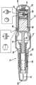
图1为穿过根据本发明的自动注射器的实施例的横截面视图,驱动活塞处于准备击发的位置;Figure 1 is a cross-sectional view through an embodiment of an autoinjector according to the present invention, with the drive piston in a ready-to-fire position;
图2为自动注射器装置的侧视图;Figure 2 is a side view of the autoinjector device;
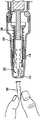
图3为穿过图1和2的自动注射器的横截面视图,注射器是伸展的且剂量被排出,并产生注射完成指示;Fig. 3 is a cross-sectional view through the autoinjector of Figs. 1 and 2, the syringe being extended and a dose being expelled, and an injection complete indication being produced;
图4为示出被拧开且被反转用于准备击发驱动活塞的自动注射器的前端的横截面视图;Figure 4 is a cross-sectional view showing the front end of the autoinjector unscrewed and inverted in preparation for firing the drive plunger;
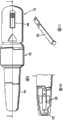
图5为示出用在图1至4的实施例中的弹簧鼓和恒力弹簧的整体透视图;Figure 5 is an overall perspective view showing a spring drum and a constant force spring used in the embodiment of Figures 1 to 4;
图6为纵向视图,装载有注射器且针护套从壳体的前端突出一短的距离;Figure 6 is a longitudinal view with the syringe loaded and the needle shield protruding a short distance from the front end of the housing;
图7示出为了拆除、牢固地握紧针护套的困难度;Figure 7 shows the difficulty of firmly grasping the needle shield for removal;
图8为穿过适于便于去除针护套的自动注射器的第二实施例的纵向横截面视图;Figure 8 is a longitudinal cross-sectional view through a second embodiment of an autoinjector adapted to facilitate removal of the needle sheath;
图9为第二实施例的自动注射器的纵向视图;Figure 9 is a longitudinal view of the autoinjector of the second embodiment;
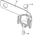
图10为壳体前端上的部分截面详图,示出了包含在图8和9的实施例中的弹簧指状夹;Figure 10 is a partial cross-sectional detail view on the front end of the housing showing the spring fingers included in the embodiment of Figures 8 and 9;
图11为弹簧指状夹的透视图;Figure 11 is a perspective view of a spring finger clip;
图12和13为示出具有护套的注射器插入到壳体前端中的连续视图,弹簧指状夹在护套的后面锁定;Figures 12 and 13 are sequential views showing the insertion of the syringe with the sheath into the front end of the housing, with the spring fingers locked behind the sheath;
图14为图13的前端的放大详图,和Figure 14 is an enlarged detail view of the front end of Figure 13, and
图15和16示出去除针护套以及针和注射器的随后向后移动的连续步骤。Figures 15 and 16 show the sequential steps of removal of the needle shield and subsequent backward movement of the needle and syringe.
具体实施方式Detailed ways
最初参照图1至5,示出了一种自动注射器装置,其包括前壳体部10和后壳体部12,前壳体部10和后壳体部12具有允许所述部被如图1至3中所看到的那样螺纹连接在一起的各自的螺纹部14、16。在图4中可以清楚地看见前和后壳体部。Referring initially to FIGS. 1 to 5, there is shown an autoinjector device comprising a
前壳体部在其前端设置有捕获式深度调节帽18,该捕获式深度调节帽18在其前端具有注射器针可以突出穿过的孔20。前壳体部10设置有内部轴环22,其可滑动地容纳由弹簧26向后偏压的注射器托架24。注射器托架24具有被设计用于容纳包括注射器柱塞30和针32的注射器28的内部孔。注射器托架24中的孔可以设计成在其前端与注射器的一部分过盈配合(interference fit),以略微抓紧注射器。注射器托架24在其前端设置有限制注射器托架在弹簧26的作用下向后移动的肋(未示出)。The front housing part is provided at its front end with a captive
后壳体部12包含缠绕在鼓36周围的恒力驱动弹簧34。恒力弹簧的外端固定至后壳体部12的内部上的固定装置(未示出)。为了旋转而将鼓36安装在驱动活塞38中,并且恒力弹簧被设计为在驱动活塞38移向其如图1中所显示的后向位置时被激励。驱动活塞38可以锁定在其准备击发位置(cocked position),并且可以通过任何合适的机构释放,但在本实施例中这是通过设置在后壳体部12上的扳机40来完成的。The
鼓36限定了其中封闭具有北磁极和南磁极的球形磁体44的凹陷42。在凹陷42的底部中设置有软铁保持器元件46,在没有其它磁体作用的情况下该软铁保持器元件46将保持球形磁体抵靠凹陷42的底部。The
后壳体部12在其壁部中设置有捕获式的固定的磁体48,该磁体48定位在驱动活塞38的操作冲程的前端。捕获式磁体48被定位成,使得当驱动活塞已经移动至完成注射的位置时,捕获式磁体和能够移动的磁体44之间的磁引力克服能够移动的磁体44和保持器46之间的引力。因此,能够移动的磁体撞击固定的磁体时产生的‘喀哒声(click)’给出了注射完成的能够听得见的指示。撞击还将产生可以由用户感觉得到的能触知的信号。The
在未示出的其它实施例中,可以设置不同类型的能够听见的、能触知的或可视的指示器。例如,可以设置协作磁体,其使得元件突出或缩入壳体中,从而用户可以感觉注射完成的指示。In other embodiments not shown, different types of audible, tactile or visual indicators may be provided. For example, cooperating magnets may be provided which cause the elements to protrude or retract into the housing so that the user can feel an indication that the injection is complete.
磁操作指示器的一个重要特征在于,它不从排出剂量的主恒力弹簧转移能量。事实上,在装置启动期间需要能量用以分开磁体,但这不会显著地减少能够用于排出剂量的能量。An important feature of the magnetically operated indicator is that it does not transfer energy from the main constant force spring that expels the dose. The fact that energy is required to separate the magnets during activation of the device does not significantly reduce the energy available for expelling a dose.
现在将描述注射循环。前和后壳体部被拧开,且通过翻转前壳体部和采用帽18的鼻部将活塞推回直到它由扳机锁定为止,而将驱动活塞38推回至准备击发的位置。随着鼓36向后移动,球形磁体44被拉动离开捕获式磁体48,并由磁引力向回拉向保持器46。The injection cycle will now be described. The front and rear housing parts are unscrewed and the
注射器随后装载到前壳体部10中的注射器托架24中,且所述壳体部被螺纹地拧在一起。在这种操作期间或之后通过合适的装置(如下文描述的)去除所述帽。自动注射器随后处于图1中所示的准备射出的状态。在射出时,鼓36和驱动部分38在驱动弹簧26的作用下被释放用于向前移动,使得驱动活塞38向前移动注射器柱塞30,以排出剂量。接近冲程的末端时,当已经排出所要求量的药物时,鼓36足够靠近捕获式磁体,使捕获式磁体用比由保持器所施加的力更大的力吸引球形磁体,以便有指示注射完成的大声的喀哒声。The syringes are then loaded into the
现在参照图6至16,现在描述便于去除针护套的配置。如在图6和7中所看到的那样,当在注射之前被与注射器组装时,典型的针护套50仅从帽18向前延伸一短的距离。这不足以使某个人能够足够紧地抓紧针护套以拆下它。因此,存在的风险是,用户通过在将注射器插入注射器托架之前去除护套50而规避这种问题,且具有针刺受伤的伴随风险。Referring now to Figures 6 to 16, arrangements to facilitate removal of the needle shield will now be described. As seen in Figures 6 and 7, a
因此,如在图8至16中看到的那样,设置了弹簧指状夹52,其固定至前壳体部或被连接到其上的部件,并向前向内延伸。弹簧指状夹52设计为使得在如图13中所示的注射器已经插入注射器托架24且克服弹簧26的偏压向前推动注射器托架时其前端可以在针护套50的向后环形肋的后面锁定。弹簧指状夹将注射器和护套保持在这一向前的位置,使得护套具有更大的部分可以用于抓紧和去除。只要通过松开护套就可去除护套并且因此克服针护套和注射器的针接口之间的摩擦配合,注射器在弹簧26的作用下向后回射,使得针安全地位于帽18内。随后如之前描述的那样,该装置被准备好用于使用。Accordingly, as seen in Figures 8 to 16,
Claims (16)
Translated fromChinesePriority Applications (1)
| Application Number | Priority Date | Filing Date | Title |
|---|---|---|---|
| CN201310578902.9ACN103585692B (en) | 2008-05-20 | 2009-05-20 | Injection device |
Applications Claiming Priority (5)
| Application Number | Priority Date | Filing Date | Title |
|---|---|---|---|
| GB0809134.0 | 2008-05-20 | ||
| GB0809134AGB2460398A (en) | 2008-05-20 | 2008-05-20 | Auto-injector having a magnetic injection indicator and a needle sheath retainer |
| US7193108P | 2008-05-27 | 2008-05-27 | |
| US61/071,931 | 2008-05-27 | ||
| PCT/GB2009/050542WO2009141650A2 (en) | 2008-05-20 | 2009-05-20 | Injection device |
Related Child Applications (1)
| Application Number | Title | Priority Date | Filing Date |
|---|---|---|---|
| CN201310578902.9ADivisionCN103585692B (en) | 2008-05-20 | 2009-05-20 | Injection device |
Publications (2)
| Publication Number | Publication Date |
|---|---|
| CN102089023Atrue CN102089023A (en) | 2011-06-08 |
| CN102089023B CN102089023B (en) | 2013-12-18 |
Family
ID=39596184
Family Applications (2)
| Application Number | Title | Priority Date | Filing Date |
|---|---|---|---|
| CN2009801185197AExpired - Fee RelatedCN102089023B (en) | 2008-05-20 | 2009-05-20 | Injection Set with Magnetic Injection Complete Indicator and Needle Sheath Removal |
| CN201310578902.9AExpired - Fee RelatedCN103585692B (en) | 2008-05-20 | 2009-05-20 | Injection device |
Family Applications After (1)
| Application Number | Title | Priority Date | Filing Date |
|---|---|---|---|
| CN201310578902.9AExpired - Fee RelatedCN103585692B (en) | 2008-05-20 | 2009-05-20 | Injection device |
Country Status (7)
| Country | Link |
|---|---|
| US (1) | US8721593B2 (en) |
| EP (1) | EP2310072A2 (en) |
| JP (1) | JP5634987B2 (en) |
| CN (2) | CN102089023B (en) |
| GB (1) | GB2460398A (en) |
| RU (1) | RU2486923C2 (en) |
| WO (1) | WO2009141650A2 (en) |
Cited By (7)
| Publication number | Priority date | Publication date | Assignee | Title |
|---|---|---|---|---|
| CN104053468A (en)* | 2011-11-24 | 2014-09-17 | 赛诺菲-安万特德国有限公司 | Needle Assembly Attachment and Removal Device |
| CN104093436A (en)* | 2011-12-15 | 2014-10-08 | Shl集团有限责任公司 | automatic injection device |
| CN105102023A (en)* | 2013-04-05 | 2015-11-25 | 诺和诺德股份有限公司 | Medication Recording Devices for Drug Delivery Devices |
| CN108392417A (en)* | 2018-04-08 | 2018-08-14 | 中国人民解放军总医院 | Hand-held dispensation apparatus |
| CN109069758A (en)* | 2015-11-27 | 2018-12-21 | 赛诺菲-安万特德国有限公司 | Injection device with protective cap allowing induction of electromagnetic fields |
| CN110402158A (en)* | 2017-03-14 | 2019-11-01 | 赛诺菲 | Injection device with acoustic feedback assembly |
| CN115429974A (en)* | 2022-09-07 | 2022-12-06 | 北京快舒尔医疗技术有限公司 | Needleless injector |
Families Citing this family (65)
| Publication number | Priority date | Publication date | Assignee | Title |
|---|---|---|---|---|
| WO2003068290A2 (en) | 2002-02-11 | 2003-08-21 | Antares Pharma, Inc. | Intradermal injector |
| HUE042286T2 (en) | 2005-01-24 | 2019-06-28 | Antares Pharma Inc | Needle-filled pre-filled syringe |
| WO2007131013A1 (en) | 2006-05-03 | 2007-11-15 | Antares Pharma, Inc. | Two-stage reconstituting injector |
| WO2007131025A1 (en) | 2006-05-03 | 2007-11-15 | Antares Pharma, Inc. | Injector with adjustable dosing |
| EP3636301A1 (en) | 2008-03-10 | 2020-04-15 | Antares Pharma, Inc. | Injector safety device |
| US8376993B2 (en) | 2008-08-05 | 2013-02-19 | Antares Pharma, Inc. | Multiple dosage injector |
| GB2463034B (en)* | 2008-08-28 | 2012-11-07 | Owen Mumford Ltd | Autoinjection devices |
| JP5732039B2 (en) | 2009-03-20 | 2015-06-10 | アンタレス・ファーマ・インコーポレーテッド | Hazardous drug injection system |
| JP5701889B2 (en)* | 2009-10-08 | 2015-04-15 | エス・ホー・エル・グループ・アクチボラゲットShl Group Ab | Drug supply device |
| GB201017363D0 (en)* | 2010-10-14 | 2010-11-24 | Owen Mumford Ltd | Injection devices |
| EP3338833B1 (en) | 2010-02-18 | 2020-07-29 | Sanofi-Aventis Deutschland GmbH | Auto-injector with a torsion spring |
| DK2536453T3 (en)* | 2010-02-18 | 2014-11-24 | Sanofi Aventis Deutschland | autoinjector |
| DK2538993T3 (en) | 2010-02-22 | 2017-02-06 | Sanofi Aventis Deutschland | Auto injector with gearbox |
| WO2011101382A1 (en)* | 2010-02-22 | 2011-08-25 | Sanofi-Aventis Deutschland Gmbh | Auto - injector with needle shroud and needle protection cap |
| CA2790283A1 (en)* | 2010-02-22 | 2011-08-25 | Sanofi-Aventis Deutschland Gmbh | Force transmission arrangement for auto-injector |
| EP2583708B1 (en)* | 2010-03-31 | 2023-02-22 | SHL Medical AG | Medicament delivery device comprising feedback signalling means |
| EP2399635A1 (en) | 2010-06-28 | 2011-12-28 | Sanofi-Aventis Deutschland GmbH | Auto-injector |
| GB201015799D0 (en) | 2010-09-21 | 2010-10-27 | Owen Mumford Ltd | Autoinjectors |
| EP2468339A1 (en)* | 2010-12-21 | 2012-06-27 | Sanofi-Aventis Deutschland GmbH | Auto-injector |
| GB201021767D0 (en)* | 2010-12-22 | 2011-02-02 | Owen Mumford Ltd | Autoinjectors |
| EP2489380A1 (en)* | 2011-02-18 | 2012-08-22 | Sanofi-Aventis Deutschland GmbH | Injection device |
| EP2489390A1 (en)* | 2011-02-18 | 2012-08-22 | Sanofi-Aventis Deutschland GmbH | Detent mechanism |
| EP2489386A1 (en) | 2011-02-18 | 2012-08-22 | Sanofi-Aventis Deutschland GmbH | Auto-injector |
| EP2489384A1 (en) | 2011-02-18 | 2012-08-22 | Sanofi-Aventis Deutschland GmbH | Auto-injector |
| EP2489381A1 (en) | 2011-02-18 | 2012-08-22 | Sanofi-Aventis Deutschland GmbH | Auto-injector |
| EP2489388A1 (en) | 2011-02-18 | 2012-08-22 | Sanofi-Aventis Deutschland GmbH | Auto-injector |
| EP2489385A1 (en) | 2011-02-18 | 2012-08-22 | Sanofi-Aventis Deutschland GmbH | Auto-injector |
| EP2489389A1 (en) | 2011-02-18 | 2012-08-22 | Sanofi-Aventis Deutschland GmbH | Detent mechanism |
| EP2489382A1 (en) | 2011-02-18 | 2012-08-22 | Sanofi-Aventis Deutschland GmbH | Auto-injector |
| EP2489387A1 (en) | 2011-02-18 | 2012-08-22 | Sanofi-Aventis Deutschland GmbH | Auto-injector |
| GB2488579A (en) | 2011-03-02 | 2012-09-05 | Owen Mumford Ltd | Autoinjector with "injection complete" indicator |
| GB2488578B (en)* | 2011-03-02 | 2017-05-24 | Owen Mumford Ltd | Injection device |
| US8496619B2 (en) | 2011-07-15 | 2013-07-30 | Antares Pharma, Inc. | Injection device with cammed ram assembly |
| US9220660B2 (en) | 2011-07-15 | 2015-12-29 | Antares Pharma, Inc. | Liquid-transfer adapter beveled spike |
| EP2583705A1 (en) | 2011-10-21 | 2013-04-24 | Sanofi-Aventis Deutschland GmbH | Indicator arrangement for an auto-injector |
| US9486583B2 (en) | 2012-03-06 | 2016-11-08 | Antares Pharma, Inc. | Prefilled syringe with breakaway force feature |
| EP4186545A1 (en) | 2012-04-06 | 2023-05-31 | Antares Pharma, Inc. | Needle assisted jet injection administration of testosterone compositions |
| US9364610B2 (en) | 2012-05-07 | 2016-06-14 | Antares Pharma, Inc. | Injection device with cammed ram assembly |
| US20130338586A1 (en)* | 2012-06-07 | 2013-12-19 | Lisa Moreno Dickinson | Injection device |
| FI3659647T3 (en) | 2013-02-11 | 2024-03-28 | Antares Pharma Inc | NEEDLE-ASSISTED SPRAY INJECTOR WITH REDUCED TRIGGER FORCE |
| US8652100B1 (en) | 2013-03-08 | 2014-02-18 | Teva Pharmaceutical Industries, Ltd. | Re-useable injector device for syringe |
| US8591463B1 (en) | 2013-03-08 | 2013-11-26 | Teva Pharmaceutical Industries Ltd. | Re-useable injector device for syringe |
| KR101780191B1 (en)* | 2013-03-08 | 2017-09-21 | 테바 파마슈티컬 인더스트리즈 리미티드 | Re-useable injector device for syringe |
| CA2905031C (en) | 2013-03-11 | 2018-01-23 | Hans PFLAUMER | Dosage injector with pinion system |
| WO2014165136A1 (en) | 2013-03-12 | 2014-10-09 | Antares Pharma, Inc. | Constant volume prefilled syringes and kits thereof |
| EP2823841A1 (en) | 2013-07-09 | 2015-01-14 | Sanofi-Aventis Deutschland GmbH | Autoinjector |
| GB2516896B (en) | 2013-08-05 | 2020-08-12 | Owen Mumford Ltd | Injection devices |
| USD745664S1 (en) | 2013-11-25 | 2015-12-15 | Teva Pharmaceutical Industries, Ltd. | Injector device for a syringe |
| EP2923714A1 (en) | 2014-03-28 | 2015-09-30 | Sanofi-Aventis Deutschland GmbH | Autoinjector triggered by skin contact |
| US10704944B2 (en) | 2014-09-14 | 2020-07-07 | Becton, Dickinson And Company | System and method for capturing dose information |
| US10971260B2 (en) | 2014-09-14 | 2021-04-06 | Becton, Dickinson And Company | System and method for capturing dose information |
| US20180015224A1 (en) | 2016-07-13 | 2018-01-18 | California Institute Of Technology | Dampers and Methods for Performing Measurements in an Autoinjector |
| USD938022S1 (en) | 2016-08-10 | 2021-12-07 | Owen Mumford Limited | Safety pen needle |
| CA3112214A1 (en) | 2018-10-05 | 2020-04-09 | Amgen Inc. | Drug delivery device having dose indicator |
| USD914208S1 (en) | 2019-06-14 | 2021-03-23 | Owen Mumford Limited | Syringe component |
| USD952136S1 (en) | 2019-06-14 | 2022-05-17 | Owen Mumford Limited | Syringe |
| USD959651S1 (en) | 2020-04-08 | 2022-08-02 | Owen Mumford Limited | Medical instrument |
| USD972745S1 (en) | 2020-05-07 | 2022-12-13 | Owen Mumford Limited | Testing device |
| EP4164715A1 (en)* | 2020-06-16 | 2023-04-19 | Bayer Aktiengesellschaft | Determination of the usage status of a device for the one-time administration of a medicament |
| USD1069617S1 (en) | 2021-03-29 | 2025-04-08 | Owen Mumford Limited | Testing device |
| CN117715670A (en)* | 2021-06-22 | 2024-03-15 | 阿克隆医疗档案和适应症动物档案公司 | Magnetic autoinjector |
| USD1078052S1 (en) | 2021-11-03 | 2025-06-03 | Owen Mumford Limited | Medical device |
| USD1071161S1 (en) | 2022-10-17 | 2025-04-15 | Owen Mumford Limited | Medical injector |
| USD1071168S1 (en) | 2022-10-17 | 2025-04-15 | Owen Mumford Limited | Medical injector |
| USD1077210S1 (en) | 2022-11-18 | 2025-05-27 | Owen Mumford Limited | Medical injector |
Citations (5)
| Publication number | Priority date | Publication date | Assignee | Title |
|---|---|---|---|---|
| US3880163A (en)* | 1973-10-26 | 1975-04-29 | Jack H Ritterskamp | Medicinal syringe actuating device |
| DE102004052219A1 (en)* | 2004-10-27 | 2006-05-04 | Tecpharma Licensing Ag | Injection devices for delivering insulin with restrictor, comprises prestressed spring washer, bi/multi stable signal generating burst/place element and releasing element that emits signal with deformation |
| US20060175427A1 (en)* | 2003-07-09 | 2006-08-10 | Berthold Jonientz | Injection apparatus comprising a position sensor |
| WO2006134153A1 (en)* | 2005-06-16 | 2006-12-21 | Novo Nordisk A/S | Method and apparatus for assisting patients in self administration of medication |
| CN201044845Y (en)* | 2006-10-28 | 2008-04-09 | 李开元 | Automatic syringe |
Family Cites Families (31)
| Publication number | Priority date | Publication date | Assignee | Title |
|---|---|---|---|---|
| JPH01119647U (en)* | 1988-02-02 | 1989-08-14 | ||
| US4959056A (en)* | 1988-06-14 | 1990-09-25 | Wayne State University | Digital dispenser |
| JP3568959B2 (en)* | 1995-03-07 | 2004-09-22 | イーライ・リリー・アンド・カンパニー | Reusable dosing device |
| US5628309A (en)* | 1996-01-25 | 1997-05-13 | Raya Systems, Inc. | Meter for electrically measuring and recording injection syringe doses |
| IT1284642B1 (en)* | 1996-05-02 | 1998-05-21 | Ermanno Greco | REFINEMENTS FOR AUTOMATIC SYRINGES FOR INJECTION |
| US6203530B1 (en)* | 1997-01-28 | 2001-03-20 | Pos-T-Vac, Inc. | Auto-injection device |
| WO1998033538A1 (en)* | 1997-02-04 | 1998-08-06 | Novo Nordisk A/S | A device for the administration of a liquid medicament suspension |
| US6319234B1 (en)* | 1997-02-12 | 2001-11-20 | Sergio Restelli | Disposable safety syringe |
| AU4883797A (en)* | 1997-11-03 | 1999-05-24 | Ermanno Greco | Self-injection device |
| JPH11299889A (en)* | 1998-02-20 | 1999-11-02 | Matsumoto Seisakusho:Kk | Alarm device for infusion and alarm device for urine pool |
| SE9803662D0 (en)* | 1998-10-26 | 1998-10-26 | Pharmacia & Upjohn Ab | autoinjector |
| US6656164B1 (en)* | 1999-09-07 | 2003-12-02 | Computer Controlled Syringe, Inc. | Retractable needle device |
| ES2365807T3 (en)* | 2001-05-16 | 2011-10-11 | ELI LILLY & COMPANY | MEDICATION INJECTOR DEVICE WITH MOTOR ASSEMBLY THAT FACILITATES REARME. |
| US6939323B2 (en)* | 2001-10-26 | 2005-09-06 | Massachusetts Institute Of Technology | Needleless injector |
| JP4339260B2 (en)* | 2002-11-25 | 2009-10-07 | テクファーマ・ライセンシング・アクチェンゲゼルシャフト | Injection device with needle protection device |
| FR2852851B1 (en)* | 2003-03-25 | 2006-01-06 | Sedat | NEEDLE PROTECTION DEVICE FOR SYRINGE, AND INJECTION DEVICE COMPRISING SYRINGE AND PROTECTIVE DEVICE |
| DE10326306B4 (en)* | 2003-06-11 | 2010-09-23 | Henke-Sass Wolf Gmbh | Syringe, in particular for veterinary applications |
| DE10330986B4 (en)* | 2003-07-09 | 2010-01-07 | Tecpharma Licensing Ag | Non-contact scanning with magnetoresistive sensor |
| US20050027255A1 (en)* | 2003-07-31 | 2005-02-03 | Sid Technologies, Llc | Automatic injector |
| EP1660158B1 (en)* | 2003-07-31 | 2008-12-24 | Sid Technologies Llc | Syringe with automatically triggered safety sleeve |
| RU2241412C1 (en)* | 2003-08-27 | 2004-12-10 | Общество с ограниченной ответственностью "Медоборудование" | Pneumatic needleless injector device |
| GB0403335D0 (en)* | 2004-02-14 | 2004-03-17 | Liversidge Barry P | Medical injector handling device |
| TWI303175B (en)* | 2004-02-26 | 2008-11-21 | Nipro Corp | Safe indwelling needle |
| GB2414398B (en)* | 2004-05-28 | 2009-04-22 | Cilag Ag Int | Injection device |
| US20060173409A1 (en)* | 2004-12-28 | 2006-08-03 | Chang-Ming Yang | Safety syring |
| US7905868B2 (en)* | 2006-08-23 | 2011-03-15 | Medtronic Minimed, Inc. | Infusion medium delivery device and method with drive device for driving plunger in reservoir |
| DE202005010389U1 (en)* | 2005-07-01 | 2005-09-08 | Tecpharma Licensing Ag | Injection unit capable of accommodating an ampule incorporates a fixed magnet and a counter-magnet on the movable piston rod of the unit |
| WO2008083875A1 (en)* | 2007-01-09 | 2008-07-17 | Shl Medical Ab | Information device |
| JP5040819B2 (en)* | 2008-06-04 | 2012-10-03 | ソニー株式会社 | Electronic equipment and electronic components |
| CN102665800B (en)* | 2009-10-21 | 2015-02-18 | 欧文蒙福德有限公司 | auto injector |
| GB201021767D0 (en)* | 2010-12-22 | 2011-02-02 | Owen Mumford Ltd | Autoinjectors |
- 2008
- 2008-05-20GBGB0809134Apatent/GB2460398A/ennot_activeWithdrawn
- 2009
- 2009-05-20RURU2010149476/14Apatent/RU2486923C2/ennot_activeIP Right Cessation
- 2009-05-20CNCN2009801185197Apatent/CN102089023B/ennot_activeExpired - Fee Related
- 2009-05-20CNCN201310578902.9Apatent/CN103585692B/ennot_activeExpired - Fee Related
- 2009-05-20USUS12/993,955patent/US8721593B2/enactiveActive
- 2009-05-20WOPCT/GB2009/050542patent/WO2009141650A2/enactiveApplication Filing
- 2009-05-20JPJP2011510051Apatent/JP5634987B2/ennot_activeExpired - Fee Related
- 2009-05-20EPEP09750128Apatent/EP2310072A2/ennot_activeWithdrawn
Patent Citations (5)
| Publication number | Priority date | Publication date | Assignee | Title |
|---|---|---|---|---|
| US3880163A (en)* | 1973-10-26 | 1975-04-29 | Jack H Ritterskamp | Medicinal syringe actuating device |
| US20060175427A1 (en)* | 2003-07-09 | 2006-08-10 | Berthold Jonientz | Injection apparatus comprising a position sensor |
| DE102004052219A1 (en)* | 2004-10-27 | 2006-05-04 | Tecpharma Licensing Ag | Injection devices for delivering insulin with restrictor, comprises prestressed spring washer, bi/multi stable signal generating burst/place element and releasing element that emits signal with deformation |
| WO2006134153A1 (en)* | 2005-06-16 | 2006-12-21 | Novo Nordisk A/S | Method and apparatus for assisting patients in self administration of medication |
| CN201044845Y (en)* | 2006-10-28 | 2008-04-09 | 李开元 | Automatic syringe |
Cited By (15)
| Publication number | Priority date | Publication date | Assignee | Title |
|---|---|---|---|---|
| CN104053468B (en)* | 2011-11-24 | 2016-08-24 | 赛诺菲-安万特德国有限公司 | Needle assemblies attachment and apparatus for removing |
| CN104053468A (en)* | 2011-11-24 | 2014-09-17 | 赛诺菲-安万特德国有限公司 | Needle Assembly Attachment and Removal Device |
| CN104093436A (en)* | 2011-12-15 | 2014-10-08 | Shl集团有限责任公司 | automatic injection device |
| US10376644B2 (en) | 2013-04-05 | 2019-08-13 | Novo Nordisk A/S | Dose logging device for a drug delivery device |
| CN105102023A (en)* | 2013-04-05 | 2015-11-25 | 诺和诺德股份有限公司 | Medication Recording Devices for Drug Delivery Devices |
| CN109069758A (en)* | 2015-11-27 | 2018-12-21 | 赛诺菲-安万特德国有限公司 | Injection device with protective cap allowing induction of electromagnetic fields |
| US10869969B2 (en) | 2015-11-27 | 2020-12-22 | Sanofi-Aventis Deutschland Gmbh | Injection device with protective cap allowing electromagnetic field induction |
| CN109069758B (en)* | 2015-11-27 | 2021-11-26 | 赛诺菲-安万特德国有限公司 | Injection device with a protective cap allowing induction of an electromagnetic field |
| CN110402158A (en)* | 2017-03-14 | 2019-11-01 | 赛诺菲 | Injection device with acoustic feedback assembly |
| US11517680B2 (en) | 2017-03-14 | 2022-12-06 | Sanofi | Injection device with an acoustic feedback arrangement |
| US12076538B2 (en) | 2017-03-14 | 2024-09-03 | Sanofi | Injection device with an acoustic feedback arrangement |
| CN108392417A (en)* | 2018-04-08 | 2018-08-14 | 中国人民解放军总医院 | Hand-held dispensation apparatus |
| CN108392417B (en)* | 2018-04-08 | 2023-09-01 | 中国人民解放军总医院 | Hand-held dispensing device |
| CN115429974A (en)* | 2022-09-07 | 2022-12-06 | 北京快舒尔医疗技术有限公司 | Needleless injector |
| CN115429974B (en)* | 2022-09-07 | 2023-09-15 | 北京快舒尔医疗技术有限公司 | Needleless injector |
Also Published As
| Publication number | Publication date |
|---|---|
| US8721593B2 (en) | 2014-05-13 |
| GB2460398A (en) | 2009-12-02 |
| JP2011520545A (en) | 2011-07-21 |
| EP2310072A2 (en) | 2011-04-20 |
| CN103585692B (en) | 2016-03-02 |
| GB0809134D0 (en) | 2008-06-25 |
| WO2009141650A2 (en) | 2009-11-26 |
| US20110077599A1 (en) | 2011-03-31 |
| RU2486923C2 (en) | 2013-07-10 |
| RU2010149476A (en) | 2012-06-27 |
| WO2009141650A3 (en) | 2010-01-21 |
| CN103585692A (en) | 2014-02-19 |
| CN102089023B (en) | 2013-12-18 |
| JP5634987B2 (en) | 2014-12-03 |
Similar Documents
| Publication | Publication Date | Title |
|---|---|---|
| CN102089023B (en) | Injection Set with Magnetic Injection Complete Indicator and Needle Sheath Removal | |
| CN102665800B (en) | auto injector | |
| US9814840B2 (en) | Injection devices | |
| JP5937617B2 (en) | Automatic injection equipment | |
| JP6382898B2 (en) | Automatic injection device with two springs for biasing the shroud forward | |
| US8052645B2 (en) | System and method for an injection using a syringe needle | |
| SE518981C2 (en) | autoinjector | |
| CN102665801A (en) | Medicament delivery device | |
| JP2016528983A (en) | Injection device | |
| JP2002502672A (en) | Improvements on medical injection devices | |
| UA91019C2 (en) | Injection device | |
| JP2010536405A (en) | Surgical needle device | |
| JP2014503287A (en) | Automatic injection device having a contact surface that provides resistance to movement of the trigger component towards the firing position | |
| JP6001553B2 (en) | Automatic injection device having means for preventing reuse and separation of the first and second body parts after operation |
Legal Events
| Date | Code | Title | Description |
|---|---|---|---|
| C06 | Publication | ||
| PB01 | Publication | ||
| C10 | Entry into substantive examination | ||
| SE01 | Entry into force of request for substantive examination | ||
| C14 | Grant of patent or utility model | ||
| GR01 | Patent grant | ||
| CF01 | Termination of patent right due to non-payment of annual fee | ||
| CF01 | Termination of patent right due to non-payment of annual fee | Granted publication date:20131218 Termination date:20180520 |