CN102088921B - Handle for surgical and dental tools - Google Patents
Handle for surgical and dental toolsDownload PDFInfo
- Publication number
- CN102088921B CN102088921BCN2009801264822ACN200980126482ACN102088921BCN 102088921 BCN102088921 BCN 102088921BCN 2009801264822 ACN2009801264822 ACN 2009801264822ACN 200980126482 ACN200980126482 ACN 200980126482ACN 102088921 BCN102088921 BCN 102088921B
- Authority
- CN
- China
- Prior art keywords
- handle
- proximal end
- surgical
- user
- concave
- Prior art date
- Legal status (The legal status is an assumption and is not a legal conclusion. Google has not performed a legal analysis and makes no representation as to the accuracy of the status listed.)
- Expired - Fee Related
Links
Images


Classifications
- A—HUMAN NECESSITIES
- A61—MEDICAL OR VETERINARY SCIENCE; HYGIENE
- A61B—DIAGNOSIS; SURGERY; IDENTIFICATION
- A61B17/00—Surgical instruments, devices or methods
- A61B17/32—Surgical cutting instruments
- A61B17/3209—Incision instruments
- A61B17/3211—Surgical scalpels, knives; Accessories therefor
- A61B17/3213—Surgical scalpels, knives; Accessories therefor with detachable blades
- B—PERFORMING OPERATIONS; TRANSPORTING
- B25—HAND TOOLS; PORTABLE POWER-DRIVEN TOOLS; MANIPULATORS
- B25G—HANDLES FOR HAND IMPLEMENTS
- B25G1/00—Handle constructions
- B25G1/10—Handle constructions characterised by material or shape
- B25G1/102—Handle constructions characterised by material or shape the shape being specially adapted to facilitate handling or improve grip
- A—HUMAN NECESSITIES
- A61—MEDICAL OR VETERINARY SCIENCE; HYGIENE
- A61B—DIAGNOSIS; SURGERY; IDENTIFICATION
- A61B17/00—Surgical instruments, devices or methods
- A61B2017/0042—Surgical instruments, devices or methods with special provisions for gripping
- A61B2017/00424—Surgical instruments, devices or methods with special provisions for gripping ergonomic, e.g. fitting in fist
- A—HUMAN NECESSITIES
- A61—MEDICAL OR VETERINARY SCIENCE; HYGIENE
- A61B—DIAGNOSIS; SURGERY; IDENTIFICATION
- A61B90/00—Instruments, implements or accessories specially adapted for surgery or diagnosis and not covered by any of the groups A61B1/00 - A61B50/00, e.g. for luxation treatment or for protecting wound edges
- A61B90/08—Accessories or related features not otherwise provided for
- A61B2090/0813—Accessories designed for easy sterilising, i.e. re-usable
- A—HUMAN NECESSITIES
- A61—MEDICAL OR VETERINARY SCIENCE; HYGIENE
- A61C—DENTISTRY; APPARATUS OR METHODS FOR ORAL OR DENTAL HYGIENE
- A61C3/00—Dental tools or instruments
Landscapes
- Health & Medical Sciences (AREA)
- Surgery (AREA)
- Engineering & Computer Science (AREA)
- Life Sciences & Earth Sciences (AREA)
- Biomedical Technology (AREA)
- Nuclear Medicine, Radiotherapy & Molecular Imaging (AREA)
- Mechanical Engineering (AREA)
- Heart & Thoracic Surgery (AREA)
- Medical Informatics (AREA)
- Molecular Biology (AREA)
- Animal Behavior & Ethology (AREA)
- General Health & Medical Sciences (AREA)
- Public Health (AREA)
- Veterinary Medicine (AREA)
- Surgical Instruments (AREA)
Abstract
Description
Translated fromChinese技术领域technical field
本发明涉及一种手柄。更特别地,本发明涉及一种用于精确的外科和牙科工具的手柄,该工具包括电外科装置和在显微外科手术中使用的外科装置。The invention relates to a handle. More particularly, the present invention relates to a handle for precision surgical and dental tools, including electrosurgical devices and surgical devices used in microsurgery.
背景技术Background technique
具有扁平紧握结构的标准解剖刀手柄并不能提供用于使得食指、拇指和中指保持就位的轮廓紧握表面。而且,具有扁平体手柄紧握结构的标准解剖刀手柄可能导致手指滑动至刀片上或者导致手指之间的非控制滚转(rolling)。Standard scalpel handles with flat grip structures do not provide a contoured grip surface for holding the index, thumb and middle fingers in place. Also, standard scalpel handles with flat handle grips can cause the fingers to slide onto the blade or cause uncontrolled rolling between the fingers.
已经实现了很多革新的解剖刀手柄设计,以便解决与解剖刀紧握的人机工程要求相关的问题。因此,已经有多种解剖刀设计来用于解决防止解剖刀的用户受到尖锐刀片损伤的问题。A number of innovative scalpel handle designs have been implemented in order to address the problems associated with the ergonomic requirements of a scalpel grip. Accordingly, various scalpel designs have been developed to address the problem of protecting the user of the scalpel from the sharp blade.
Shackelford,Sr.等的美国专利No.5531754介绍了一种能伸缩的刀片,该刀片安装在刀片保持器机构上,该刀片保持器机构装于盖壳体内。刀片保持器机构包括偏压在鞘上的弹性弹簧夹。US Patent No. 5,531,754 to Shackelford, Sr. et al. describes a retractable blade mounted on a blade holder mechanism housed within a cover housing. The blade holder mechanism includes resilient spring clips biased against the sheath.
George等的US7101382包括一种能伸缩的解剖刀装置,该解剖刀装置有两个可释放的锁定元件。当解剖刀刀片处于伸出位置时,各可释放锁定元件可接近,用于通过手指压力而压低,以便使得伸出的刀片缩回。可释放的锁定元件装在盖壳体的相对边缘(顶部和底部)上,并在沿它的长度的大约一半处。必须在用于使得伸出的解剖刀刀片缩回至壳体中时压低该可释放的锁定元件。US7101382 to George et al. includes a retractable scalpel device having two releasable locking elements. When the scalpel blade is in the extended position, each releasable locking element is accessible for depression by finger pressure to retract the extended blade. Releasable locking elements are mounted on opposite edges (top and bottom) of the cover housing and about halfway along its length. The releasable locking element must be depressed when used to retract the extended scalpel blade into the housing.
Kanodia等的US7153317B2包括一次性的安全外科手术解剖刀,它包括:手柄,该手柄有固定在它上面的刀片;以及滑动安装的防护装置。当解剖刀使用时,防护装置运动至使得刀片露出的缩回位置,该防护装置锁定在该位置。当不使用时,防护装置运动至覆盖刀片的伸出位置。防护装置有在它的外表面上的槽,以便提供用于外科医生的更好紧握件。US7153317B2 to Kanodia et al. includes a disposable safety surgical scalpel comprising: a handle with a blade secured thereto; and a slide mounted guard. When the scalpel is in use, the guard is moved to a retracted position exposing the blade, in which position the guard is locked. When not in use, the guard moves to an extended position covering the blade. The guard has grooves on its outer surface to provide a better grip for the surgeon.
Brown的美国专利No.101325涉及一种用于解剖刀的新颖、初始和美观的设计。该设计的特征在于手柄的结构,其中,壁和上部边缘有横向槽或锯齿,且有锥形倾斜的上部和底部边缘。US Patent No. 101325 to Brown relates to a novel, original and aesthetically pleasing design for a scalpel. The design is characterized by the structure of the handle, in which the walls and upper edge have transverse grooves or serrations, and there are conical sloping upper and bottom edges.
Yaniv等的US D535749介绍了一种用于解剖刀的美观设计。US D535749 to Yaniv et al. describes an aesthetically pleasing design for a scalpel.
Webb的美国专利No.5578050涉及一种用于覆盖解剖刀手柄的橡胶套筒。US Patent No. 5,578,050 to Webb relates to a rubber sleeve for covering the handle of a scalpel.
Lehtonen的美国设计专利No.D4516305设计一种解剖刀手柄,它没有提供用于定位手指的凹入部分。US Design Patent No. D4516305 to Lehtonen contemplates a scalpel handle that does not provide recessed portions for positioning the fingers.
Ziemer的美国专利No.7150754涉及解剖刀刀片的对齐,而不需要眼接触。为了实现该目的,该发明提供了一种手柄区域,它包括三个侧面,这三个侧面布置成使得手柄区域的横截面有三角形包迹线,且至少一个侧面提供有触觉识别特征。手柄区域的横截面的三角形包迹线有利于在中指、拇指和食指之间合适地保持解剖刀刀片保持器,相对于手指,该解剖刀刀片保持器和固定在它上面的解剖刀只能采取绕解剖刀刀片保持器的手柄区域的中心轴线的三个不同旋转状态。将运动限制为只有三个旋转状态使得用户通过他的触觉通过他的手指来确定解剖刀刀片保持器的对齐以及固定在它上面的解剖刀的对齐。手柄有圆弧三角形形状。圆角拐角有助于更好地紧握,另外防止用户在拐角上伤害自身或者损坏防护手套,且尺寸不需要象触觉识别特征设计为凹口时那样大。US Patent No. 7,150,754 to Ziemer relates to alignment of scalpel blades without eye contact. To achieve this object, the invention provides a handle area comprising three sides arranged such that the cross-section of the handle area has a triangular envelope and at least one side is provided with a tactile identification feature. The triangular envelope of the cross-section of the handle area facilitates proper retention of the scalpel blade holder between the middle finger, thumb and forefinger, with respect to which fingers, the scalpel blade holder and the scalpel fixed thereon can only take Three different states of rotation about the central axis of the handle area of the scalpel blade holder. Restricting the motion to only three rotational states allows the user to determine the alignment of the scalpel blade holder and the alignment of the scalpel secured thereto by his sense of touch through his fingers. The handle has a rounded triangle shape. Rounded corners allow for a better grip, additionally prevent the user from injuring themselves or damaging the protective glove on the corners, and do not need to be as large in size as if the tactile identification feature were designed as a notch.
Sullivan等的美国专利申请2006/0041266包括一种外科手术解剖刀手柄的远侧部分,它有扩大的手指压力部分。该部分为整个手柄长度的大约三分之一,并有在它的右侧和左侧侧壁处的较小凸起。手指压力部分具有底部的稍微弯曲和在顶面处的凹入部分。该凹入部分的宽度和长度与成年人食指的指垫一样大,即从食指的尖端至第一指节的指垫。手指压力部分的顶面比本体部分的顶面更宽。手柄的本体部分为三角形。右侧面和左侧面形成“V”形,或者是具有尖端线的20-60度锐角。US Patent Application 2006/0041266 to Sullivan et al. includes a distal portion of a surgical scalpel handle having an enlarged finger pressure portion. This portion is approximately one third of the length of the overall handle and has smaller protrusions at its right and left side walls. The finger pressure portion has a slight curvature at the bottom and a concave portion at the top surface. The width and length of this concave portion are as large as the finger pad of an adult's index finger, ie from the tip of the index finger to the finger pad of the first knuckle. The top surface of the finger pressure portion is wider than the top surface of the body portion. The body portion of the handle is triangular in shape. The right and left flanks form a "V" shape, or an acute angle of 20-60 degrees with a pointed line.
扁平或三角形的装置对于用户并不舒服,因为这些手柄并不充分满足紧握的人机工程需要。扁平本体的手柄提供了用于手指的有纹理紧握表面,但是它太小或太窄,以致于不能长时间地舒适地紧握,或者一旦紧握将限制手的自由运动。而且,在手指之间没有滑动或滚转(该滑动或滚转将伴随着因此对用户或病人的损伤)危险的情况下,扁平本体手柄的紧握结构基本上只能在一个位置使用。具有三角形横截面的紧握件可以很容易地进行方向定位,不过它们不能提供在人机工程上舒适的工作方案。三角形装置的一个边缘可能钻入用户的手指中。Flat or triangular devices are uncomfortable for the user, as these handles do not adequately meet the ergonomic needs of a tight grip. The handle of the flat body provides a textured gripping surface for the fingers, but is too small or too narrow to comfortably grip for long periods of time, or restricts free hand movement once gripped. Furthermore, the grip structure of the flat body handle can basically only be used in one position without the risk of slipping or rolling between the fingers, which would be accompanied by consequential damage to the user or the patient. Grips with a triangular cross-section allow easy orientation, but they do not provide an ergonomically comfortable working solution. One edge of the triangular device may dig into the user's finger.
尽管已经减轻了与高效使用解剖刀相关的很多问题(例如定位和保持合适紧握),但是现有技术公开的紧握件不能解决减小疲劳(该疲劳由于在外科手术过程中需要调节手指的相对位置和保持解剖刀刀片的可靠位置控制和对齐而产生)的要求,而且,这些紧握件没有涉及消除为了维护现有技术的任意机构或卫生特征而对附加人员的需求。While many of the problems associated with efficient use of a scalpel (such as positioning and maintaining a proper grip) have been alleviated, the grips disclosed in the prior art do not address reducing fatigue due to the need to adjust the fingers during surgery. relative position and maintaining reliable positional control and alignment of the scalpel blades), and these grips do not address the need for additional personnel to maintain any of the mechanisms or hygienic features of the prior art.
发明内容Contents of the invention
因此,本发明的目的是消除现有技术解剖刀手柄的缺点,并提供一种解剖刀手柄,它有独特的间隔开的凹入部分,该凹入部分适应手指形状,而不是手指压力,从而使得解剖刀手柄能够舒适地长时间握紧,使得手柄能够在可选位置握紧,不会受到干手套或湿手套的阻碍,使得制造简单以及需要最小维护或不需要维护。Accordingly, it is an object of the present invention to eliminate the disadvantages of prior art scalpel handles and to provide a scalpel handle that has unique spaced apart indentations that conform to the shape of the fingers, rather than finger pressure, thereby Allowing a scalpel handle to be comfortably gripped for extended periods of time, enabling the handle to be gripped in selectable positions without being obstructed by dry or wet gloves, enabling ease of manufacture and requiring minimal or no maintenance.
本发明的还一目的是提供一种解剖刀手柄,它有靠近仪器操作端的四个模制凹形凹入部分,它还具有卵形形状,有附加的用户食指支承件,从而明显有利于精确的外科手术操作。Still another object of the present invention is to provide a scalpel handle having four molded concave recesses near the operating end of the instrument, which also has an oval shape with additional support for the user's index finger, thereby significantly facilitating precision surgical operations.
本发明通过提供一种用于精确的外科和牙科工具的人机工程手柄来实现上述目的,该手柄设计成方便用户手紧握的定位,它包括:纵向延伸的本体,该本体为基本卵形截面,并提供有四个基本凹形的凹入部分,这些凹入部分定位成靠近手柄的近端,第一凹形凹入部分沿手柄的顶表面提供,第二和第三凹入部分沿侧表面提供,且第四凹入部分沿本体的底表面提供,所述凹入部分相互定位成提供分别与用户的拇指、食指和中指的连续的交界面。The present invention achieves the above objects by providing an ergonomic handle for precise surgical and dental tools, the handle is designed to facilitate the positioning of the user's hand grip, it includes: a longitudinally extending body, the body is substantially oval cross section, and are provided with four substantially concave recessed portions positioned near the proximal end of the handle, the first concave recessed portion is provided along the top surface of the handle, the second and third recessed portions are provided along the The side surfaces are provided, and a fourth recessed portion is provided along the bottom surface of the body, the recessed portions being mutually positioned to provide continuous interfaces with the user's thumb, index finger, and middle finger, respectively.
在本发明的优选实施例中,提供了一种人机工程的手柄,其中,手柄的顶部的表面区域的轮廓设置成这样,从它的远端延伸向它的近端并接近近端地提供有凹形凹入部分,该凹形凹入部分延伸和并入升高的脊状表面支承件中,该脊状表面支承件朝着手柄的近端成角度倾斜。In a preferred embodiment of the present invention there is provided an ergonomic handle wherein the surface area of the top of the handle is contoured to extend from its distal end to its proximal end and provide There is a concave recess that extends and merges into a raised ridged surface support that is angled toward the proximal end of the handle.
在本发明的另一优选实施例中,提供了一种人机工程的手柄,其中,四个凹入部分相互间隔开大约90°。In another preferred embodiment of the present invention, an ergonomic handle is provided, wherein the four concave portions are spaced about 90° apart from each other.
在本发明的还一优选实施例中,提供了一种人机工程的手柄,其中,纵向延伸的本体有轴线,第一凹形凹入部分与至少一个其它凹入部分相比朝着轴线更深地切入本体中。In yet another preferred embodiment of the present invention there is provided an ergonomic handle wherein the longitudinally extending body has an axis and the first concave recess is deeper towards the axis than at least one other recess cut into the body.
在本发明的还一优选实施例中,提供了一种人机工程的手柄,其中,手柄在它的近端沿纵向轴线提供有用于安装可交换外科手术刀片和仪器的装置。In yet another preferred embodiment of the present invention there is provided an ergonomic handle wherein the handle is provided at its proximal end along the longitudinal axis with means for mounting exchangeable surgical blades and instruments.
在本发明的还一优选实施例中,提供了一种人机工程的手柄,其中,脊状表面支承件升高,并有凸出的凸形曲线,以便能够将用户的食指定位成充分靠近手柄本体的近端,同时防止食指滑向近端。In yet another preferred embodiment of the present invention, an ergonomic handle is provided in which the ridged surface support is raised and has a raised convex curve to enable the user's index finger to be positioned sufficiently close to the The proximal end of the handle body while preventing the index finger from sliding to the proximal end.
在本发明的最优选实施例中,提供了一种人机工程的手柄,其中,外科手术工具是解剖刀。In a most preferred embodiment of the present invention there is provided an ergonomic handle wherein the surgical tool is a scalpel.
附图说明Description of drawings
下面将结合某些优选实施例参考附图介绍本发明,从而可以更充分地理解本发明。The present invention will be described below in connection with certain preferred embodiments with reference to the accompanying drawings, so that the present invention can be more fully understood.
下面将特别参考附图,应当强调,所示特征只是作为实例,用于示例说明本发明的优选实施例,且认为这样将最有利和最容易地理解本发明的原理和概念方面的说明。在这个方面,并不试图以比基本理解本发明所需更详细地表示本发明的结构细节,结合附图的说明将使得本领域技术人员清楚可以怎样实施本发明的多种形式。With particular reference now to the drawings, it should be emphasized that the illustrated features are by way of example only, illustrative of preferred embodiments of the invention and which are considered to be the most beneficial and easiest to understand from the description of the principles and conceptual aspects of the invention. In this regard, no attempt is made to show structural details of the invention in more detail than is required for a fundamental understanding of the invention, the description taken in conjunction with the drawings will make apparent to those skilled in the art how the invention may be practiced in its various forms.
附图中:In the attached picture:
图1是本发明的手柄的优选实施例的透视图;Figure 1 is a perspective view of a preferred embodiment of the handle of the present invention;
图2是手柄的侧视图和它的剖视图;Fig. 2 is a side view of the handle and its sectional view;
图3是图2中的剖视图的多个分解透视剖视图;FIG. 3 is a multiple exploded perspective sectional view of the sectional view in FIG. 2;
图4是本发明的手柄的俯视剖视图;Fig. 4 is a top sectional view of the handle of the present invention;
图5A是本发明的手柄的左侧视图,表示了背部凹入部分和底部凹入部分;Figure 5A is a left side view of the handle of the present invention showing the back recess and the bottom recess;
图5B是本发明的手柄的右侧视图,表示了背部凹入部分和底部凹入部分;Figure 5B is a right side view of the handle of the present invention showing the back recess and the bottom recess;
图5C是本发明的手柄的远侧端视图;Figure 5C is a distal end view of the handle of the present invention;
图5D是本发明的手柄的近侧端视图,表示了它的柄;Figure 5D is a proximal end view of the handle of the present invention showing its shaft;
图5E是本发明的手柄的俯视图;Figure 5E is a top view of the handle of the present invention;
图5F是本发明的手柄的仰视图,表示了侧部凹入部分;Figure 5F is a bottom view of the handle of the present invention showing side recesses;
图6A表示了当使用标准解剖刀手柄时手指滑动和受到伤害的危险;Figure 6A shows the risk of finger slippage and injury when using a standard scalpel handle;
图6B表示了使用本发明的手柄,因此防止手指滑动。Figure 6B shows the use of the handle of the present invention, thus preventing fingers from slipping.
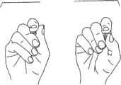
图7A表示了当标准的解剖刀手柄在手指之间旋转时手持现有技术手柄和缺乏控制的剖视图;Figure 7A shows a cross-sectional view of holding a prior art handle and lack of control when a standard scalpel handle is rotated between the fingers;
图7B表示了当本发明的手柄在手指之间旋转时手持手柄和手柄的使用的剖视图;Figure 7B shows a cross-sectional view of the handle and use of the handle when the handle of the present invention is rotated between the fingers;
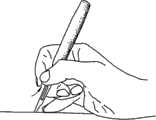
图8A表示了在现有技术的标准解剖刀手柄上的更高手紧握位置;以及Figure 8A shows a higher hand grip position on a prior art standard scalpel handle; and
图8B表示了在本发明的手柄上的更低手紧握位置。Figure 8B shows the lower hand grip position on the handle of the present invention.
具体实施方式Detailed ways
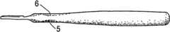
图1中表示了外科手术解剖刀手柄1,用于与一次性外科手术刀片2结合使用,该一次性外科手术刀片2可安装在从手柄1的近端纵向伸出的柄3上。手柄1包括纵向延伸的本体4,该本体4为基本卵形横截面,并由变化宽度和形状的连续卵形而形成。手柄有可模制形成于其中的四个凹形凹入部分5(未示出)、6、7和8,这些凹形凹入部分邻接手柄1的近端。A surgical scalpel handle 1 is shown in FIG. 1 for use in conjunction with a disposable surgical blade 2 mountable on a
根据本发明的一个实施例,凹入部分5和6设计成分别容纳中指和拇指,凹入部分7和8设计成大致分别容纳食指和中指,因此有利于用户紧握。这样,在使用时,用户的手指不会限制在手柄的紧握位置。本发明实施例的凹入部分的总体结构使得用户能够在各个紧握位置舒适地紧握手柄1。According to one embodiment of the present invention, the
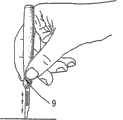
根据本发明的一个实施例,如图1、5A和5B中所示,顶部凹入部分7设计成容纳右手用户的食指9,如图6B中所示,从而与食指的球部分和尖端的大部分接合。如图1和图5F中所示,侧部凹入部分6设计成容纳用户的拇指10,如图7B中所示,从而与拇指10的球部分的大部分接合。如图1、5A和5B中所示,底部凹入部分8设计成容纳用户的中指11的一部分,如图7B中所示,在第一关节处并在邻近食指位置的一侧。如图5F中所示,侧部凹入部分5设计成容纳用户的中指12的一部分,如图7B中所示。当为左手用户时,侧部凹入部分的位置将颠倒。因此,侧部凹入部分用于容纳中指和拇指将涉及与上面关于右手用户所述相同的所述中指和拇指部分的接合。According to one embodiment of the present invention, as shown in FIGS. 1 , 5A and 5B, the top recessed
在图1、5A和5B中所示的顶部凹形凹入部分7有低于手柄表面大约2.0mm的优选最大深度,这优选是比侧部凹入部分5和6和底部凹入部分8稍微更深,如图5F中所示,该侧部凹入部分5和6有大约1.0mm的优选最大深度,且如图1和5A中所示,该底部凹入部分8有在它的最低点处的大约0.3mm的优选最大深度。The top
在图1、5A和5B中,还可以看见附加的脊状表面支承件13,该脊状表面支承件13用作用户食指的抵靠件,从而提供了进入手指的柔软垫中的可靠紧握件,并在切割和进行贴近工作时防止滑动。脊状表面支承件13布置在手柄的近端的前面处,并形成至顶部凹入部分的最高和近侧点处的弯曲。脊状表面支承件13的中点可以在图2的截面A-A中看见,它有大约6.1mm的优选水平长度和大约9.2mm的优选竖直高度。In Figures 1, 5A and 5B, an additional ridged
如图2中所示,截面A-A布置在脊状表面支承件13的最前侧点处并最靠近手柄1的近端,图3中还表示了截面A-A的特定梨形形状。截面A-A具有大约9.2mm的优选竖直高度和大约6.1mm的优选水平宽度。截面B-B布置在顶部凹形凹入部分7的、最靠近手柄前部的第二端点处,如图2中所示,且它的特征形状在图3中表示。截面B-B具有大约11.5mm的优选竖直高度和大约6.2mm的优选水平宽度。尽管截面A-A和B-B布置成横向于手柄1的相同纵向轴线并大致在该纵向轴线上,但是两个截面在高度和宽度上有明显区别;它们的高度差优选是大约2.3mm,宽度差优选是大约0.1mm。当食指布置在顶部凹入部分7上时,该差异能够使得食指舒适和有所需的精确性。As shown in FIG. 2 , the section A-A is arranged at the most forward point of the ridged
截面C-C沿向下倾斜曲线布置成在顶部凹形凹入部分内,如图2中所示,且它的特定形状如图3中表示。截面C-C具有大约10.6mm的优选竖直高度和大约6.3的优选水平宽度。截面D-D布置在沿顶部凹形凹入部分7的中点处,如图2中所示,它的特定形状也在图3中表示。截面D-D具有大约9.7mm的优选竖直高度和大约6.5的优选水平宽度。截面E-E沿向上倾斜曲线布置成靠近凹形凹入部分7的顶部,如图2中所示,且它的特定形状也在图3中表示。截面E-E有大约11mm的优选竖直高度和大约6.7的优选水平宽度。截面F-F布置在凹形凹入部分7的顶部的最高点处,如图2中所示,且它的特定形状在图3中表示。截面F-F有大约12mm的优选竖直高度和大约7mm的优选水平宽度。截面G-G基本沿手柄1的柄3的中部,如图2中所示,它的特定形状在图3中表示。截面G-G具有大约12.7mm的优选竖直高度和大约8.4mm的优选水平宽度。Section C-C is arranged along a downwardly sloping curve within the top concave recess, as shown in FIG. 2 , and its specific shape is shown in FIG. 3 . Section C-C has a preferred vertical height of about 10.6 mm and a preferred horizontal width of about 6.3 mm. Section D-D is arranged at the midpoint along the top
分别容纳用户的拇指和中指的两个侧部凹形凹入部分5和6如图1和5F中所示,并构成在测量值、形状和尺寸方面彼此镜像。不过,与中指相比,拇指的接合具有更宽和更大的表面面积,根据本发明的一个实施例,侧部凹入部分的相同尺寸保证对于两者同样方便。如图1、5A和5B中所示,底部凹入部分8允许用户的中指从侧部凹入部分至底部凹入部分,或者能够舒适地互换。The two side
图6A表示了与本发明的独特设计的安全性相比较,当使用标准解剖刀手柄时手指滑动的危险以及伴随对用户或病人产生的伤害,本发明的独特设计防止手指滑动,如图6B所示。Figure 6A shows the risk of finger slippage and the attendant injury to the user or patient when using a standard scalpel handle, compared to the safety of the unique design of the present invention, which prevents finger slippage, as shown in Figure 6B Show.
图7B表示了本发明的手柄在与如图7A中所示的标准解剖刀形状相比时的有利操纵性。具有本发明特征并如上所述的手柄设计、形状和人机工程特征的紧握件将方便更多地与手柄接触,从而提供从手柄的竖直表面至水平表面的逐渐调节,并能够安全地进行贴近工作,并降低了突然手指滑动或在用户手指之间进行非控制滚转的可能性。而且,本发明的手柄的结构使得用户能够在手柄并不进行非控制滚转的情况下使得手柄旋转,还使得用户能够不费力地控制手柄,同时使得手柄保持稳定。Figure 7B illustrates the advantageous maneuverability of the handle of the present invention when compared to the standard scalpel shape as shown in Figure 7A. A grip having the features of the present invention and the handle design, shape and ergonomic features described above will facilitate greater contact with the handle, thereby providing gradual adjustment from the vertical to the horizontal surface of the handle and enabling safe Work close and reduce the possibility of sudden finger slides or uncontrolled rolls between the user's fingers. Furthermore, the structure of the handle of the present invention enables the user to rotate the handle without uncontrolled roll of the handle, and also allows the user to control the handle with little effort while maintaining the handle stable.
本发明使得作为支承件的用户小手指能够更近地锚固,用于更精确的工作。用户的紧握件越靠近手柄前部地进行贴近工作,他就越容易有机会有效地使用仪器。The invention enables closer anchoring of the user's little finger as a support for more precise work. The closer the user's grip works close to the front of the handle, the more likely he has the opportunity to use the instrument effectively.
因此,图8A表示了当使用现有技术的标准设计的解剖刀时需要相对于切割区域保持更高或不合适的手指紧握位置。在本发明的手柄上的更低手指紧握位置能够有舒适的手指紧握延伸部分,超过了图8B中所示的手柄中的凹入部分的限制。Thus, Figure 8A illustrates the need to maintain a high or improper finger grip position relative to the cutting area when using a prior art standard design scalpel. The lower finger grip position on the handle of the present invention enables a comfortable finger grip extension beyond the limitations of the recessed portion in the handle shown in Figure 8B.
而且,并不使用有纹理的紧握件(因为它们的柔性或多孔性而使得消毒困难),而是根据本发明的一个实施例,本发明的手柄由无纹理的材料来制造,从而产生容易消毒的成形紧握件。Also, instead of using textured grips (which make sterilization difficult because of their flexibility or porosity), according to one embodiment of the invention, the handle of the invention is made of a non-textured material, thereby creating an easy Sterilized shaped grips.
本领域技术人员应当知道,本发明并不局限于前述实施例的细节,本发明可以以其它特定形式来实施,而并不脱离本发明的精神或基本特性。因此,本发明的实施例是作为示例说明,而不是限定,本发明的范围由附加权利要求来表示,而不是前述说明,因此,在权利要求的等效意义和范围内的所有变化都将包含在本发明中。Those skilled in the art should understand that the present invention is not limited to the details of the foregoing embodiments, and that the present invention can be implemented in other specific forms without departing from the spirit or essential characteristics of the present invention. Therefore, the embodiments of the present invention are illustrated rather than limited, and the scope of the present invention is indicated by the appended claims, rather than the foregoing description, and therefore, all changes within the equivalent meaning and scope of the claims will be embraced. In the present invention.
Claims (5)
Translated fromChineseApplications Claiming Priority (3)
| Application Number | Priority Date | Filing Date | Title |
|---|---|---|---|
| IL192739AIL192739A (en) | 2008-07-10 | 2008-07-10 | Handle for surgical and dental tools |
| IL192,739 | 2008-07-10 | ||
| PCT/IL2009/000060WO2010004541A1 (en) | 2008-07-10 | 2009-01-15 | Handle for surgical and dental tools |
Publications (2)
| Publication Number | Publication Date |
|---|---|
| CN102088921A CN102088921A (en) | 2011-06-08 |
| CN102088921Btrue CN102088921B (en) | 2013-09-25 |
Family
ID=40785383
Family Applications (1)
| Application Number | Title | Priority Date | Filing Date |
|---|---|---|---|
| CN2009801264822AExpired - Fee RelatedCN102088921B (en) | 2008-07-10 | 2009-01-15 | Handle for surgical and dental tools |
Country Status (7)
| Country | Link |
|---|---|
| US (1) | US8850662B2 (en) |
| EP (1) | EP2341848B1 (en) |
| CN (1) | CN102088921B (en) |
| ES (1) | ES2523348T3 (en) |
| IL (1) | IL192739A (en) |
| PL (1) | PL2341848T3 (en) |
| WO (1) | WO2010004541A1 (en) |
Families Citing this family (41)
| Publication number | Priority date | Publication date | Assignee | Title |
|---|---|---|---|---|
| US8745825B2 (en)* | 2008-07-10 | 2014-06-10 | Scalpal Llc | Gripping sleeve device for precision instruments |
| IL192739A (en) | 2008-07-10 | 2015-07-30 | Scalpal Llc | Handle for surgical and dental tools |
| USD660966S1 (en) | 2011-09-09 | 2012-05-29 | Sheild Peter J | Dental instrument sleeve |
| IL219885A0 (en)* | 2012-05-20 | 2012-07-31 | Scalpal Llc | Surgical instrument suitable for use in deep surgery |
| WO2014037933A1 (en)* | 2012-09-06 | 2014-03-13 | Scalpal Llc | Surgical knife and tools adapted for simplified blade removal |
| AU2013242815A1 (en)* | 2012-10-12 | 2014-05-01 | Peter Dominic Fegan | A Hand Implement |
| CN102922541A (en)* | 2012-11-22 | 2013-02-13 | 高永军 | Kitchen knife capable of relieving wrist fatigue |
| WO2014102764A1 (en)* | 2012-12-31 | 2014-07-03 | Scalpal Llc | Finger-held instrument adapted for supporting or shielding a user's finger |
| US20150047153A1 (en)* | 2013-08-13 | 2015-02-19 | Yu-Lin Chiang | Handle structure |
| WO2015033352A2 (en)* | 2013-09-04 | 2015-03-12 | Mohit Kumar Khandelwal | A finger mountable dental hand piece device |
| USD735334S1 (en)* | 2013-09-18 | 2015-07-28 | Eye Care And Cure Asia Pte Ltd | Anterior capsulotomy device |
| CN103479404A (en)* | 2013-09-23 | 2014-01-01 | 南方医科大学 | Hand-shape-adaptable multifunctional surgical operation handle |
| IL230808A0 (en) | 2014-02-04 | 2014-09-30 | Eliyahu Gitman | Hand-held tool having resilient seal mountable between a body portion and a working tip of the tool |
| WO2015129461A1 (en)* | 2014-02-28 | 2015-09-03 | マニー株式会社 | Medical knife |
| US10588642B2 (en) | 2014-05-15 | 2020-03-17 | Gauthier Biomedical, Inc. | Molding process and products formed thereby |
| US20160270301A1 (en)* | 2015-03-19 | 2016-09-22 | Estwing Manufacturing Company, Inc. | Machete |
| US11234899B2 (en) | 2017-05-11 | 2022-02-01 | Scalpal Llc | Grasping facilitators and uses thereof and kits involving the same |
| TWI756218B (en) | 2016-04-20 | 2022-03-01 | 美商菲歐普提斯公司 | Probe cover for an oximeter device, kit and method for forming a kit |
| US10722158B2 (en) | 2016-04-20 | 2020-07-28 | Vioptix, Inc. | Handheld oximeter probe with replaceable probe tip |
| TWI765885B (en) | 2016-04-21 | 2022-06-01 | 美商菲歐普提斯公司 | Method and device for determining tissue oxygen saturation with melanin correction |
| JP6992003B2 (en) | 2016-04-22 | 2022-02-03 | ビオプティックス・インコーポレイテッド | Determining Absolute Tissue Oxygen Saturation and Relative Tissue Oxygen Saturation |
| TWI754641B (en) | 2016-04-22 | 2022-02-11 | 美商菲歐普提斯公司 | Oximeter device and oximeter system having the same |
| JP7146733B2 (en) | 2016-07-18 | 2022-10-04 | ビオプティックス・インコーポレイテッド | Oxygen measurement device with laparoscopic dilation |
| USD807148S1 (en) | 2016-08-26 | 2018-01-09 | Vikon Surgical, Llc | Elastomeric resilient handle sleeve |
| GB2553510B (en)* | 2016-08-30 | 2020-03-25 | Dyson Technology Ltd | A handheld appliance |
| USD787913S1 (en) | 2016-09-19 | 2017-05-30 | Farrell E Robinson | Elastomeric resilient handle sleeve |
| USD812744S1 (en) | 2016-09-22 | 2018-03-13 | Farrell E Robinson | Elastomeric resilient handle sleeve |
| US11969864B2 (en) | 2017-05-11 | 2024-04-30 | Scalpal Llc | Multi-tier torque enhancer driver and/or receiver and method of using same |
| RU174810U1 (en)* | 2017-07-05 | 2017-11-02 | Марина Николаевна Гуртовая | Scalpel |
| US11154380B2 (en) | 2017-10-26 | 2021-10-26 | King Abdulaziz University | Dental restoration scalpel |
| USD898195S1 (en) | 2017-11-09 | 2020-10-06 | Scalpal Llc | Handle configuration |
| USD898194S1 (en) | 2017-11-09 | 2020-10-06 | Scalpal Llc | Handle configuration |
| USD911524S1 (en) | 2017-11-13 | 2021-02-23 | Scalpal Llc | Handle configuration |
| USD888955S1 (en)* | 2018-01-31 | 2020-06-30 | Beijing Smtp Technology Co., Ltd. | Ultrasonic cutter head |
| USD883756S1 (en)* | 2018-05-08 | 2020-05-12 | 3Coil Limited | Knife |
| USD925738S1 (en)* | 2018-07-25 | 2021-07-20 | Progressive Medical, Inc. | Surgical blade |
| US11883015B2 (en)* | 2018-09-23 | 2024-01-30 | Ning Miao Su | Retractor used to assist cuff implantation, tissue repositioning and other applications |
| USD915592S1 (en)* | 2019-01-18 | 2021-04-06 | Nico Corporation | Dissection device |
| USD978519S1 (en)* | 2019-11-14 | 2023-02-21 | Orthoglam Inc. | Crutch sleeve |
| DE102019219489A1 (en)* | 2019-12-12 | 2021-06-17 | Hansgrohe Se | Sanitary pull-out hose fitting |
| US12329408B2 (en) | 2021-07-16 | 2025-06-17 | Michael Joseph Wawrzyniak | Handle design of a scalpel for stable operation thereof |
Citations (8)
| Publication number | Priority date | Publication date | Assignee | Title |
|---|---|---|---|---|
| US3974833A (en)* | 1973-03-19 | 1976-08-17 | Durden Iii John G | Disposable electrosurgical cautery having optional suction control feature |
| EP0090256A1 (en)* | 1982-03-16 | 1983-10-05 | Martor-Argentax E.H. Beermann KG | Handle for tool with an e.g. retractable blade |
| DE8712442U1 (en)* | 1987-06-11 | 1987-11-12 | Montén, Claes, Dr.med.dent., 96231 Staffelstein | Handle for dental instruments |
| WO1991006405A1 (en)* | 1989-10-30 | 1991-05-16 | Bertus Johannes Reitsma | Knife grip |
| DE10042567A1 (en)* | 2000-08-22 | 2002-03-21 | Univ Dresden Tech | Dental instrument handle, has surface provided with flat cells having specific length and width |
| US6502314B1 (en)* | 1999-05-24 | 2003-01-07 | Mccatty Michael S. | Knife handle |
| WO2006031729A2 (en)* | 2004-09-13 | 2006-03-23 | University Of Massachusetts | Adapter sleeve |
| CN1914006A (en)* | 2003-12-30 | 2007-02-14 | 康伦达 | tool handle |
Family Cites Families (93)
| Publication number | Priority date | Publication date | Assignee | Title |
|---|---|---|---|---|
| US796980A (en)* | 1904-05-07 | 1905-08-15 | Robert D Andrews | Tooth-brush. |
| US2173451A (en) | 1938-05-11 | 1939-09-19 | Lorber Charles | Finger fitting holder |
| US2782764A (en) | 1954-03-12 | 1957-02-26 | Allen Bronston | Writing instrument |
| US3247594A (en) | 1963-03-27 | 1966-04-26 | David M Nosonowitz | Handle for endodontic instrument |
| US4149811A (en) | 1975-10-03 | 1979-04-17 | Coffman Melvin C | Style handle |
| USD253219S (en)* | 1977-04-26 | 1979-10-23 | Meyer Dolph A | Orange peeler |
| US4167347A (en) | 1977-10-19 | 1979-09-11 | Hoyle James E | Writing instrument removable finger grip |
| USD258310S (en) | 1978-10-19 | 1981-02-17 | Iolab Corporation | Scalpel handle |
| USD269357S (en) | 1981-02-11 | 1983-06-14 | Little People Limited | Writing instrument |
| USD292104S (en) | 1983-07-14 | 1987-09-29 | Keller Jr Fred | Handle for a writing instrument or the like |
| US4526547A (en) | 1984-07-26 | 1985-07-02 | Rusk Chris E | Writing aid and method of teaching using the writing aid |
| US4832604A (en) | 1986-04-07 | 1989-05-23 | Rusk Chris E | Writing aid |
| USD298439S (en) | 1986-04-07 | 1988-11-08 | Rusk Chris E | Writing aid |
| USD313624S (en) | 1986-10-09 | 1991-01-08 | Vili Brandt | Shaft for a writing implement |
| USD307601S (en) | 1987-02-09 | 1990-05-01 | The Gillette Company | Marking instrument |
| USD307444S (en) | 1987-02-09 | 1990-04-24 | The Gillette Company | Grip portion for a writing instrument |
| USD318295S (en) | 1988-04-22 | 1991-07-16 | Hsing Ying & Co. | Writing instrument finger grip |
| USD330079S (en) | 1990-04-12 | 1992-10-06 | Survival Technology, Inc. | Auto-injector for liquid medicate |
| US5056945A (en) | 1990-09-04 | 1991-10-15 | W. T. Rogers Company | Writing instrument grip |
| US5143463A (en) | 1990-12-24 | 1992-09-01 | Pozil Richard L | Writing aid |
| US5176649A (en) | 1991-01-28 | 1993-01-05 | Akio Wakabayashi | Insertion device for use with curved, rigid endoscopic instruments and the like |
| US5626430A (en) | 1991-02-07 | 1997-05-06 | Bistrack; Carl | Adaptable pressuring writing instrument holder |
| US5237984A (en) | 1991-06-24 | 1993-08-24 | Xomed-Treace Inc. | Sheath for endoscope |
| US5228851A (en) | 1991-10-01 | 1993-07-20 | Burton Clarence E | Single-use disposable prophylactic elastic sleeve |
| US5988909A (en) | 1991-12-02 | 1999-11-23 | Luke, Jr.; Stanley C. | Writing instrument with ergonomic grip |
| US5217001A (en) | 1991-12-09 | 1993-06-08 | Nakao Naomi L | Endoscope sheath and related method |
| WO1994000305A1 (en) | 1992-06-30 | 1994-01-06 | Rubin Burton S | Ergonomic hand-held implement |
| US5531754A (en) | 1992-07-24 | 1996-07-02 | Shackelford, Sr.; Howard L. | Retractable surgical blade device and associated method |
| US5785443A (en) | 1993-04-20 | 1998-07-28 | Evo Pen Inc. | Ergonomic snap-fit cartridge pen |
| US5440784A (en)* | 1993-05-17 | 1995-08-15 | Hull; Harold L. | Ergonomic hand grip |
| USD361345S (en) | 1994-03-11 | 1995-08-15 | Chen Barnabas C | Writing instrument |
| US5578050A (en) | 1994-04-04 | 1996-11-26 | Webb; Nicholas J. | Ergonomic surgical scalpel sleeve |
| USD359758S (en) | 1994-05-19 | 1995-06-27 | Pentel Of America, Ltd. | Grip for a writing instrument |
| USD373143S (en) | 1994-10-10 | 1996-08-27 | Little People Limited | Grip for a writing implement |
| GB9422399D0 (en)* | 1994-11-07 | 1995-01-04 | Little People Ltd | Digit positioning sleeve |
| USD372047S (en) | 1995-02-03 | 1996-07-23 | Adatte Design, S.A. | Pen |
| US6601272B2 (en)* | 1998-05-08 | 2003-08-05 | John O. Butler Company | Dental hygiene system handle |
| US5975909A (en)* | 1998-09-17 | 1999-11-02 | Ritchie; Samuel E. | Utensil manipulation training tools and method |
| JP3058776U (en) | 1998-10-29 | 1999-06-22 | モリト株式会社 | Writing implement |
| US6146038A (en) | 1999-04-22 | 2000-11-14 | A.T.X. International, Inc. | Variable contour grip |
| USD561828S1 (en) | 1999-06-28 | 2008-02-12 | Pat Beckwith Wesselmann | Ergonometric writing device |
| US6390818B2 (en) | 2000-01-03 | 2002-05-21 | Marann Ferranti | Ergonomic grip for dental instruments |
| EP1163088B1 (en)* | 2000-01-25 | 2006-06-21 | Felo-Werkzeugfabrik Holland-Letz Gmbh | Handle for hand and garden tools, and handle sets and tool sets combined with handles of this type |
| USD457630S1 (en) | 2000-04-20 | 2002-05-21 | Lm-Instruments Oy | Scalpel handle |
| USD440605S1 (en) | 2000-06-12 | 2001-04-17 | Kotobuki & Co., Ltd. | Finger gripping device for a writing instrument |
| US6408524B1 (en)* | 2000-06-16 | 2002-06-25 | Yin-Chu Lai | Tableware grip structure with comfortable touch feeling |
| US6554515B2 (en) | 2000-06-22 | 2003-04-29 | Societe Bic S.A. | Ergonomic writing instrument |
| US6343885B1 (en) | 2000-09-19 | 2002-02-05 | David G. Heyne | Writing instrument with hand grip |
| US6296409B1 (en) | 2000-10-09 | 2001-10-02 | Adstracts, Inc. | Flexible grip with promotional indicia and handheld articles incorporating same |
| US6809508B2 (en)* | 2000-10-20 | 2004-10-26 | Ethicon Endo-Surgery, Inc. | Detection circuitry for surgical handpiece system |
| US7357773B2 (en)* | 2002-03-07 | 2008-04-15 | Ams Research Corporation | Handle and surgical article |
| US6752555B2 (en) | 2002-06-14 | 2004-06-22 | William T. Geddes | Attachment providing comfortable grip |
| USD480423S1 (en) | 2002-08-07 | 2003-10-07 | Dong Guan Szu Mao Stationery Gifts, Co., Ltd. | Pen |
| EP1393685B1 (en) | 2002-08-30 | 2005-06-15 | SIS AG Surgical Instrument Systems | Scalpel blade holder and scalpel |
| DE10245086A1 (en)* | 2002-09-27 | 2004-04-08 | Trisa Holding Ag | Method of making a toothbrush |
| US7101382B2 (en) | 2002-11-12 | 2006-09-05 | Samuel George | Retractable scalpel |
| USD499141S1 (en) | 2002-12-19 | 2004-11-30 | Societe Bic | Writing instrument |
| US7654989B2 (en) | 2003-04-08 | 2010-02-02 | C. R. Bard, Inc. | Ureteral access sheath |
| US6772994B1 (en)* | 2003-04-22 | 2004-08-10 | Mayhew Tool Products | Pry bar handle |
| US8032991B2 (en)* | 2003-05-05 | 2011-10-11 | Mayhew Steel Products, Inc. | Pry bar ergonomic handle |
| US7153317B2 (en) | 2003-05-30 | 2006-12-26 | Ribbel International Limited | Disposable guarded surgical scalpel |
| TWD103979S1 (en) | 2003-07-24 | 2005-04-01 | 斑馬股份有限公司 | Ballpoint pen |
| US20050150083A1 (en)* | 2004-01-08 | 2005-07-14 | Roberts D. D. | Utility handle providing enhanced grip and comfort |
| US20050155185A1 (en)* | 2004-01-16 | 2005-07-21 | Tamooz C.S. Ltd. | Ergonomic handset |
| USD515389S1 (en)* | 2004-07-29 | 2006-02-21 | Huang-Tung Hsu | Screwdriver handle |
| USD504700S1 (en) | 2004-08-04 | 2005-05-03 | Chuang Cheng-Hua | Pen cap |
| US20060041266A1 (en)* | 2004-08-17 | 2006-02-23 | Sullivan Stephen J | Surgical scalpel |
| USD533944S1 (en) | 2004-08-17 | 2006-12-19 | Sullivan Stephen J | Surgical scalpel |
| US20080051813A1 (en)* | 2004-09-13 | 2008-02-28 | University Of Massachusetts | Adapter Sleeve |
| US20060252989A1 (en) | 2005-05-04 | 2006-11-09 | Sightline Technologies Ltd. | Endoscopic apparatus provided with inflatable propelling sleeve |
| US20060263142A1 (en) | 2005-05-19 | 2006-11-23 | Edward Goldberg | Writing instrument with a resilient end |
| USD535749S1 (en) | 2005-11-01 | 2007-01-23 | Bel-Art Products, Inc. | Scalpel |
| US7647704B2 (en)* | 2005-12-30 | 2010-01-19 | Petersen Thomas D | Handle with removable disposable surgical blade |
| USD563474S1 (en) | 2006-04-11 | 2008-03-04 | Sanford, L.P. | Clip for a writing instrument |
| USD560803S1 (en) | 2006-05-08 | 2008-01-29 | Cryocath Technologies Inc. | Handle for medical device |
| CA2955328C (en) | 2006-05-18 | 2018-04-10 | Smart Medical Systems Ltd. | Flexible endoscope system and functionality |
| US20080163463A1 (en)* | 2007-01-10 | 2008-07-10 | Sunex International, Inc. | Tool handle |
| US10278682B2 (en) | 2007-01-30 | 2019-05-07 | Loma Vista Medical, Inc. | Sheaths for medical devices |
| USD568475S1 (en) | 2007-03-21 | 2008-05-06 | Sandel Medical Industries, Llc | Scalpel |
| USD589619S1 (en)* | 2007-07-05 | 2009-03-31 | Jung Wu | Scalpel handle for left handed |
| USD590062S1 (en) | 2007-07-05 | 2009-04-07 | Jung Wu | Scalpel handle for right handed |
| USD620107S1 (en) | 2007-09-17 | 2010-07-20 | Q Park Medical Limited | Endoscope sheath assembly |
| USD632391S1 (en) | 2008-06-12 | 2011-02-08 | Scalpal Llc | Scalpel |
| US8434954B2 (en) | 2008-07-10 | 2013-05-07 | Scalpal Llc | Handle for writing instruments |
| US8745825B2 (en) | 2008-07-10 | 2014-06-10 | Scalpal Llc | Gripping sleeve device for precision instruments |
| IL192739A (en) | 2008-07-10 | 2015-07-30 | Scalpal Llc | Handle for surgical and dental tools |
| USD633142S1 (en) | 2009-09-16 | 2011-02-22 | 3M Innovative Properties Company | Writing instrument with sheet dispenser |
| USD642214S1 (en) | 2009-09-30 | 2011-07-26 | Scalpal Llc | Writing instrument |
| USD687950S1 (en) | 2009-09-30 | 2013-08-13 | Scalpal Llc | Sleeve |
| USD651648S1 (en) | 2010-01-30 | 2012-01-03 | Fritz Luettgens | Writing utensil grip |
| US20120010468A1 (en) | 2010-07-06 | 2012-01-12 | Adel Afridi | System of disposable contoured sleeves for flexible endoscopes |
| USD660421S1 (en) | 2010-10-04 | 2012-05-22 | Gauthier Biomedical Inc. | Tool grip |
| IL219885A0 (en) | 2012-05-20 | 2012-07-31 | Scalpal Llc | Surgical instrument suitable for use in deep surgery |
- 2008
- 2008-07-10ILIL192739Apatent/IL192739A/enactiveIP Right Grant
- 2008-11-21USUS12/275,754patent/US8850662B2/enactiveActive
- 2009
- 2009-01-15EPEP09787426.7Apatent/EP2341848B1/enactiveActive
- 2009-01-15PLPL09787426Tpatent/PL2341848T3/enunknown
- 2009-01-15WOPCT/IL2009/000060patent/WO2010004541A1/enactiveApplication Filing
- 2009-01-15CNCN2009801264822Apatent/CN102088921B/ennot_activeExpired - Fee Related
- 2009-01-15ESES09787426.7Tpatent/ES2523348T3/enactiveActive
Patent Citations (8)
| Publication number | Priority date | Publication date | Assignee | Title |
|---|---|---|---|---|
| US3974833A (en)* | 1973-03-19 | 1976-08-17 | Durden Iii John G | Disposable electrosurgical cautery having optional suction control feature |
| EP0090256A1 (en)* | 1982-03-16 | 1983-10-05 | Martor-Argentax E.H. Beermann KG | Handle for tool with an e.g. retractable blade |
| DE8712442U1 (en)* | 1987-06-11 | 1987-11-12 | Montén, Claes, Dr.med.dent., 96231 Staffelstein | Handle for dental instruments |
| WO1991006405A1 (en)* | 1989-10-30 | 1991-05-16 | Bertus Johannes Reitsma | Knife grip |
| US6502314B1 (en)* | 1999-05-24 | 2003-01-07 | Mccatty Michael S. | Knife handle |
| DE10042567A1 (en)* | 2000-08-22 | 2002-03-21 | Univ Dresden Tech | Dental instrument handle, has surface provided with flat cells having specific length and width |
| CN1914006A (en)* | 2003-12-30 | 2007-02-14 | 康伦达 | tool handle |
| WO2006031729A2 (en)* | 2004-09-13 | 2006-03-23 | University Of Massachusetts | Adapter sleeve |
Also Published As
| Publication number | Publication date |
|---|---|
| IL192739A0 (en) | 2009-02-11 |
| IL192739A (en) | 2015-07-30 |
| US8850662B2 (en) | 2014-10-07 |
| PL2341848T3 (en) | 2015-02-27 |
| US20100005630A1 (en) | 2010-01-14 |
| WO2010004541A1 (en) | 2010-01-14 |
| CN102088921A (en) | 2011-06-08 |
| EP2341848B1 (en) | 2014-08-13 |
| ES2523348T3 (en) | 2014-11-25 |
| EP2341848A1 (en) | 2011-07-13 |
Similar Documents
| Publication | Publication Date | Title |
|---|---|---|
| CN102088921B (en) | Handle for surgical and dental tools | |
| US8745825B2 (en) | Gripping sleeve device for precision instruments | |
| US8409231B2 (en) | Scalpel handle | |
| EP2623152A1 (en) | Gripping device and method of use thereof | |
| US10357271B2 (en) | Surgical instrument | |
| US20170265887A1 (en) | Adjustable Curette | |
| US10285729B2 (en) | Finger-held instrument adapted for supporting or shielding a user's finger | |
| US20140304929A1 (en) | Oral utensil | |
| US8434954B2 (en) | Handle for writing instruments | |
| ES2797108T3 (en) | Disposable Kerrison Gouge Forceps | |
| WO2014209504A9 (en) | Ergonomic dental tools | |
| US20250099204A1 (en) | Ergonomic dental elevator | |
| US12311523B2 (en) | Ergonomic instrument handling system | |
| US20170196572A1 (en) | Elastomeric resilient handle sleeve | |
| US20190274667A1 (en) | Ergonomic handle | |
| US6176159B1 (en) | Ergonomic pliers | |
| US20250205026A1 (en) | Handheld oral care device | |
| CN218419922U (en) | Handle and reamer for orthopedic operation tool | |
| CN222265344U (en) | Surgical instrument | |
| US12239339B2 (en) | Collapsible handle design for debriders | |
| CN209984266U (en) | Scalpel for neurosurgery | |
| AU2023204251A1 (en) | An improved hand held massage tool for multifunctional use. aio - all in one therapy massage tool. | |
| BR202021007581U2 (en) | MANUAL USE SURGICAL DEVICE THAT PRESENTS TWO CONFORMATIONS | |
| JP2504211Y2 (en) | Scalpel | |
| WO2006031729A2 (en) | Adapter sleeve |
Legal Events
| Date | Code | Title | Description |
|---|---|---|---|
| C06 | Publication | ||
| PB01 | Publication | ||
| C10 | Entry into substantive examination | ||
| SE01 | Entry into force of request for substantive examination | ||
| C14 | Grant of patent or utility model | ||
| GR01 | Patent grant | ||
| CF01 | Termination of patent right due to non-payment of annual fee | Granted publication date:20130925 Termination date:20210115 | |
| CF01 | Termination of patent right due to non-payment of annual fee |