CN102088551A - Camera adjustment system and method - Google Patents
Camera adjustment system and methodDownload PDFInfo
- Publication number
- CN102088551A CN102088551ACN200910310796XACN200910310796ACN102088551ACN 102088551 ACN102088551 ACN 102088551ACN 200910310796X ACN200910310796X ACN 200910310796XACN 200910310796 ACN200910310796 ACN 200910310796ACN 102088551 ACN102088551 ACN 102088551A
- Authority
- CN
- China
- Prior art keywords
- video camera
- control signal
- signal
- unit
- camera
- Prior art date
- Legal status (The legal status is an assumption and is not a legal conclusion. Google has not performed a legal analysis and makes no representation as to the accuracy of the status listed.)
- Pending
Links
Images

Classifications
- H—ELECTRICITY
- H04—ELECTRIC COMMUNICATION TECHNIQUE
- H04N—PICTORIAL COMMUNICATION, e.g. TELEVISION
- H04N7/00—Television systems
- H04N7/18—Closed-circuit television [CCTV] systems, i.e. systems in which the video signal is not broadcast
- H04N7/183—Closed-circuit television [CCTV] systems, i.e. systems in which the video signal is not broadcast for receiving images from a single remote source
- H04N7/185—Closed-circuit television [CCTV] systems, i.e. systems in which the video signal is not broadcast for receiving images from a single remote source from a mobile camera, e.g. for remote control
- H—ELECTRICITY
- H04—ELECTRIC COMMUNICATION TECHNIQUE
- H04N—PICTORIAL COMMUNICATION, e.g. TELEVISION
- H04N23/00—Cameras or camera modules comprising electronic image sensors; Control thereof
- H04N23/60—Control of cameras or camera modules
- H04N23/63—Control of cameras or camera modules by using electronic viewfinders
- H—ELECTRICITY
- H04—ELECTRIC COMMUNICATION TECHNIQUE
- H04N—PICTORIAL COMMUNICATION, e.g. TELEVISION
- H04N23/00—Cameras or camera modules comprising electronic image sensors; Control thereof
- H04N23/60—Control of cameras or camera modules
- H04N23/66—Remote control of cameras or camera parts, e.g. by remote control devices
- H04N23/661—Transmitting camera control signals through networks, e.g. control via the Internet
- H—ELECTRICITY
- H04—ELECTRIC COMMUNICATION TECHNIQUE
- H04N—PICTORIAL COMMUNICATION, e.g. TELEVISION
- H04N23/00—Cameras or camera modules comprising electronic image sensors; Control thereof
- H04N23/60—Control of cameras or camera modules
- H04N23/695—Control of camera direction for changing a field of view, e.g. pan, tilt or based on tracking of objects
Landscapes
- Engineering & Computer Science (AREA)
- Multimedia (AREA)
- Signal Processing (AREA)
- Studio Devices (AREA)
- Accessories Of Cameras (AREA)
Abstract
Translated fromChinese
Description
Translated fromChinese技术领域technical field
本发明涉及一种摄影机调整系统及方法。The invention relates to a camera adjustment system and method.
背景技术Background technique
传统摄像机装置只能通过特定的控制器进行操作,其一般是通过人为调整镜头的位置来改变拍摄视角。在远程拍摄操作中,即使用者距离摄像机镜头较远时,要改变摄像机镜头的位置则需要其他人的帮助,如此比较麻烦。Traditional camera devices can only be operated through a specific controller, which generally changes the shooting angle of view by manually adjusting the position of the lens. In the remote shooting operation, that is, when the user is far away from the camera lens, other people's help is required to change the position of the camera lens, which is troublesome.
发明内容Contents of the invention
鉴于以上内容,有必要提供一种在远程拍摄操作中可由使用者控制摄像机位置的摄影机调整系统及方法。In view of the above, it is necessary to provide a camera adjustment system and method in which the user can control the position of the camera during the remote shooting operation.
一种摄影机调整系统,包括:A camera adjustment system comprising:
一显示屏,用于显示影像;a display screen for displaying images;
一重力感测器,用于感测使用者头部的运动并发出电信号;A gravity sensor for sensing the movement of the user's head and sending out electrical signals;
一处理单元,所述处理单元将所述电信号转化为控制信号;a processing unit that converts the electrical signal into a control signal;
一网络单元,用于接收所述控制信号;及a network unit for receiving said control signal; and
一摄像机,用于通过网络单元接收控制信号并根据所述控制信号控制所述摄像机的运动,所述摄像机还用于拍摄影像并将拍摄得到的影像通过网络单元传送至所述显示屏显示。A camera is used to receive a control signal through the network unit and control the movement of the camera according to the control signal. The camera is also used to shoot images and transmit the captured images to the display screen through the network unit for display.
一种摄影机调整方法,包括以下步骤:A camera adjustment method, comprising the following steps:
重力感测器感应使用者的头部的运动并将使用者的头部的运动转化为电信号;The gravity sensor senses the movement of the user's head and converts the movement of the user's head into an electrical signal;
将对应使用者的头部运动的电信号转化为位移信息;Convert the electrical signal corresponding to the user's head movement into displacement information;
将所述位移信息转化为控制信号;converting the displacement information into a control signal;
根据所述控制信号控制摄像机的运动;controlling the movement of the camera according to the control signal;
控制摄像机拍摄影像;及control the camera to capture images; and
通过一显示屏显示所述摄像机拍摄的影像。The image captured by the camera is displayed through a display screen.
上述摄影机调整系统及方法通过所述重力感测器将使用者的头部的运动转化为电信号,所述运算单元将所述电信号转化为位移信息,所述控制单元将所述位移信息转化为控制信号,所述控制信号控制所述摄像机运动以对应拍摄不同的图像。The camera adjustment system and method above convert the movement of the user's head into electrical signals through the gravity sensor, the computing unit converts the electrical signals into displacement information, and the control unit converts the displacement information into is a control signal, and the control signal controls the movement of the camera to correspondingly capture different images.
附图说明Description of drawings
图1是本发明摄影机调整系统的较佳实施方式的方框图。FIG. 1 is a block diagram of a preferred embodiment of the camera adjustment system of the present invention.
图2是图1中的眼镜的立体图。Fig. 2 is a perspective view of the glasses in Fig. 1 .
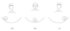
图3是本发明摄影机调整系统调整摄像机的示意图。Fig. 3 is a schematic diagram of adjusting the camera by the camera adjusting system of the present invention.
图4是本发明摄影机调整方法的较佳实施方式的流程图。FIG. 4 is a flow chart of a preferred embodiment of the camera adjustment method of the present invention.
主要元件符号说明Description of main component symbols
具体实施方式Detailed ways
下面结合附图及较佳实施方式对本发明作进一步详细描述:Below in conjunction with accompanying drawing and preferred embodiment the present invention is described in further detail:
请参考图1,本发明摄影机调整系统的较佳实施方式包括一重力感测器10、一显示屏20、一处理单元30、一网络单元40、一摄像机200及一轨道300。所述摄影机调整系统可根据使用者的头部运动对应调整所述摄像机200在所述轨道300上的位置,从而拍摄到不同的图像。所述重力感测器10、显示屏20、网络单元40均与所述处理单元30相连。Please refer to FIG. 1 , a preferred embodiment of the camera adjustment system of the present invention includes a
请继续参考图2,所述重力感测器10与显示屏20安装于一眼镜25上,所述眼镜25配戴于使用者的头部,所述显示屏20正对着使用者的眼部,所述重力感测器设置于眼镜25的镜框上。所述网络单元40通过一有线网络或无线网络与所述摄像机200通信。Please continue to refer to FIG. 2, the
所述重力感测器10用于感测使用者的头部的运动,如头部左右转动、抬头及低头等。所述重力感测器10根据使用者的头部的运动发出一第一电信号给所述处理单元30。所述重力感测器10感测物体的运动并发出对应的电信号已为业界所习知,在此不再赘述。The
所述显示屏20用于显示所述摄像机200传来的影像。本实施方式中,所述显示屏20可为一液晶显示屏或者LED显示屏。The
所述处理单元30包括一运算单元32及一控制单元34。The
所述运算单元32用于将所述重力感测器10发出的第一电信号转化为第一位移信息。如使用者的头向右转45度时,所述运算单元32计算出第一位移信息为(+45度,0度)。其中,第一位移信息中包括使用者的头部左右转动的角度以及抬头或低头的角度。比如,一第一位移信息为(-45度,0度),即表示使用者的头部向左转动了45度且没有抬头或低头。The
所述控制单元34用于将所述运算单元32发出的第一位移信息转化为一第一控制信号。比如,第一位移信息为(+45度,0度)时,所述控制单元34发出第一控制信号控制所述摄像机200沿轨道向右移动45度。The
所述处理单元30通过所述网络单元40与所述摄像机200通信。所述网络单元40可为一习知的局域网、无线局域网及通用无线分组业务(General Packet Radio Service,GPRS)等。所述第一控制信号通过所述网络单元40传送给所述摄像机200。The
所述摄像机200架设于所述轨道300上且所述摄像机200可以在所述轨道300上滑动。本实施方式中,所述轨道300为一弧形轨道,其它实施方式中所述轨道300也为其它类型的轨道,如一圆形轨道。The
所述摄像机200包括一信号发送/接收单元210、一驱动单元220、一摄像单元230。所述驱动单元220与所述信号发送/接收单元210相连,所述摄像单元230与所述信号发送/接收单元210及驱动单元220均相连。The
所述信号发送/接收单元210可为一天线。所述信号发送/接收单元210用于将所述摄像单元230拍摄的影像发送给所述网络单元40及接收所述控制单元34发出的第一控制信号。比如,当第一位移信息为(+45度,0度)时,所述控制单元34通过所述网络单元40发出所述控制所述摄像机200沿轨道向右移动45度的第一控制信号,所述信号发送/接收单元210接收该第一控制信号。The signal sending/receiving
所述驱动单元220根据所述第一控制信号改变所述摄像机200在所述轨道300的位置。比如当第一控制信号为控制所述摄像机200沿轨道向右移动45度时,所述驱动单元220控制所述摄像机200偏离原来位置沿弧形轨道300向右移动45度。The
所述驱动单元220可为一云台(图未示)。所述云台包括一马达及一马达驱动器。所述马达驱动器用于根据所述第一控制信号控制所述马达转动。比如当第一控制信号为控制所述摄像机200沿轨道向右移动45度时,所述马达驱动器控制马达转动以使得所述摄像机200偏离原来位置沿弧形轨道300向右移动45度。The
请参考图3,下面以具体实施例对本发明摄影机调整系统调整所述摄像机200进行说明。Please refer to FIG. 3 , the camera adjustment system of the present invention to adjust the
当使用者的头部佩戴安装有所述重力感测器10及显示屏20的眼镜25且使用者的头部没有运动时,所述运算单元32计算出第一位移信息为(0度,0度)。所述控制单元34将所述第一位移信息(0度,0度)转化为第一控制信号,即控制所述摄像机200保持不动。所述驱动单元220通过所述信号发送/接收单元210接收所述第一控制信号,所述驱动单元220控制所述摄像机200保持于所述轨道300上的一初始位置上,如图3(b)所示。When the user's head wears the glasses 25 on which the
当佩戴安装有所述重力感测器10及显示屏20的眼镜25的使用者的头部向左转动45度时,所述运算单元32计算出第一位移信息为(-45度,0度)。所述控制单元34将所述第一位移信息(-45度,0度)转化为第一控制信号,即控制所述摄像机200向左移动45度。所述驱动单元220通过所述信号发送/接收单元210接收所述第一控制信号,所述驱动单元220控制所述摄像机200偏离所述初始位置向左移动45度,如图3(c)所示。When the head of the user who wears the glasses 25 equipped with the
当使用者的头部佩戴所述重力感测器10及显示屏20且使用者的头部向右转动45度时,所述运算单元32计算出第一位移信息为(+45度,0度)。所述控制单元34将所述第一位移信息(+45度,0度)转化为第一控制信号,即控制所述摄像机200向右移动45度。所述驱动单元220通过所述信号发送/接收单元210接收所述第一控制信号,所述驱动单元220控制所述摄像机200偏离所述初始位置向右移动45度,如图3(a)所示。When the user's head wears the
当使用者抬头45度时,所述运算单元32计算出第一位移信息为(0度,+45度)。所述控制单元34将所述第一位移信息(0度,+45度)转化为第一控制信号,即控制所述摄像机200上仰45度。所述驱动单元220通过所述信号发送/接收单元210接收所述第一控制信号,所述驱动单元220控制所述摄像机200上仰45度。When the user raises the head 45 degrees, the
当使用者低头45度时,所述运算单元32计算出第一位移信息为(0度,-45度)。所述控制单元34将所述第一位移信息(0度,-45度)转化为第一控制信号,即控制所述摄像机200下倾45度。所述驱动单元220通过所述信号发送/接收单元210接收所述第一控制信号,所述驱动单元220控制所述摄像机200下倾45度。When the user lowers the head by 45 degrees, the
在其他实施方式中,所述重力感测器10还可以感测使用者的头部前进或后退的动作。所述重力感测器10发出一第二电信号给所述运算单元32。所述运算单元32接收所述重力感测器10发出的第二电信号并得到一第二位移信息。如使用者的头部前进10cm时,所述运算单元32计算出第二位移信息为10cm;使用者的头部后退10cm时,所述运算单元32计算出第二位移信息为-10cm。In other embodiments, the
所述控制单元34用于将所述运算单元32发出的第二位移信息控制转化为一第二控制信号。比如,第一位移信息为10cm时,所述控制单元34发出第二控制信号控制所述摄像机200的镜头伸长1cm。The
所述驱动单元220通过所述信号发送/接收单元210接收所述第二控制信号,所述驱动单元220根据第二控制信号控制所述摄像单元230的镜头伸缩对应的尺寸以放大或缩小拍摄画面,从而使得当用户的头部前进时即可观看到放大的画面、当用户的头部后退时即可观看到缩小的画面。The driving
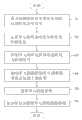
请参考图4,本发明摄影机调整方法的较佳实施方式包括以下步骤。Please refer to FIG. 4 , a preferred embodiment of the camera adjustment method of the present invention includes the following steps.
步骤S1:通过重力感测器10将使用者的头部的运动转化为电信号。本实施方式中,所述重力感测器10佩戴于使用者的头部。Step S1: Convert the movement of the user's head into electrical signals through the
步骤S2:所述运算单元32将所述电信号转化为位移信息。比如,如使用者的头向右转45度时,所述运算单元32计算出位移信息为(+45度,0度)。Step S2: The computing
步骤S3:所述控制单元34将所述位移信息转化为控制信号。比如,当位移信息为(+45度,0度)时,所述控制信号为控制所述摄像机200向右移动45度。Step S3: The
步骤S4:所述驱动单元220根据所述控制信号调整所述摄像机200在所述轨道300上的位置。比如,当所述控制信号为控制所述摄像机200向右移动45度时,所述驱动单元220控制所述摄像机200偏离原来位置沿弧形轨道300向右移动45度。Step S4: The driving
步骤S5:所述摄像单元230拍摄影像。Step S5: The
步骤S6:所述显示屏20显示所述摄像单元230拍摄的影像。Step S6: The
使用者依据上述方法根据显示屏20上的图像控制自己头部的动作继续控制摄像单元230在轨道上的位置拍摄图像。According to the above method, the user controls the movement of his head according to the image on the
上述摄影机调整系统及方法通过所述重力感测器10将使用者的头部的运动转化为电信号,所述运算单元32将所述电信号转化为位移信息,所述控制单元34将所述位移信息转化为控制信号,所述驱动单元220根据所述控制信号控制所述摄像机200的位置,摄像机镜头的俯仰角度及镜头的焦距等以方便对影像的拍摄。The above camera adjustment system and method convert the movement of the user's head into electrical signals through the
Claims (9)
Priority Applications (2)
| Application Number | Priority Date | Filing Date | Title |
|---|---|---|---|
| CN200910310796XACN102088551A (en) | 2009-12-03 | 2009-12-03 | Camera adjustment system and method |
| US12/770,773US20110135290A1 (en) | 2009-12-03 | 2010-04-30 | Camera adjusting system and method |
Applications Claiming Priority (1)
| Application Number | Priority Date | Filing Date | Title |
|---|---|---|---|
| CN200910310796XACN102088551A (en) | 2009-12-03 | 2009-12-03 | Camera adjustment system and method |
Publications (1)
| Publication Number | Publication Date |
|---|---|
| CN102088551Atrue CN102088551A (en) | 2011-06-08 |
Family
ID=44082115
Family Applications (1)
| Application Number | Title | Priority Date | Filing Date |
|---|---|---|---|
| CN200910310796XAPendingCN102088551A (en) | 2009-12-03 | 2009-12-03 | Camera adjustment system and method |
Country Status (2)
| Country | Link |
|---|---|
| US (1) | US20110135290A1 (en) |
| CN (1) | CN102088551A (en) |
Cited By (5)
| Publication number | Priority date | Publication date | Assignee | Title |
|---|---|---|---|---|
| CN103365294A (en)* | 2012-03-29 | 2013-10-23 | 鸿富锦精密工业(深圳)有限公司 | Unmanned aerial vehicle control system and method thereof |
| CN104581033A (en)* | 2013-10-18 | 2015-04-29 | 爱玛丽欧有限公司 | Control method and control system for monitoring camera |
| WO2017011945A1 (en)* | 2015-07-17 | 2017-01-26 | 深圳市尚腾影科技有限公司 | Attitude data input apparatus and method, and cradle head control apparatus and method |
| CN106911891A (en)* | 2017-02-15 | 2017-06-30 | 惠州Tcl移动通信有限公司 | The method and system that a kind of VR auxiliary is taken photo by plane |
| CN107395922A (en)* | 2016-05-17 | 2017-11-24 | 智眸科技有限公司 | Tracking control assembly |
Families Citing this family (4)
| Publication number | Priority date | Publication date | Assignee | Title |
|---|---|---|---|---|
| US8767083B2 (en)* | 2011-05-17 | 2014-07-01 | Fairchild Semiconductor Corporation | Remote display glasses camera system and method |
| CN104469292B (en)* | 2014-11-27 | 2017-09-19 | 国网上海市电力公司 | An attitude self-correcting pan-tilt camera control device and method thereof |
| WO2018008101A1 (en)* | 2016-07-06 | 2018-01-11 | 株式会社オプティム | Image provision system, image provision method, and program |
| CN108459622B (en)* | 2017-02-21 | 2021-05-07 | 昊翔电能运动科技(昆山)有限公司 | Load gravity center adjusting system and method of self-stabilizing cradle head |
Citations (5)
| Publication number | Priority date | Publication date | Assignee | Title |
|---|---|---|---|---|
| US5610678A (en)* | 1993-12-30 | 1997-03-11 | Canon Kabushiki Kaisha | Camera including camera body and independent optical viewfinder |
| US6148100A (en)* | 1996-12-20 | 2000-11-14 | Bechtel Bwxt Idaho, Llc | 3-dimensional telepresence system for a robotic environment |
| US20010045978A1 (en)* | 2000-04-12 | 2001-11-29 | Mcconnell Daniel L. | Portable personal wireless interactive video device and method of using the same |
| CN1753461A (en)* | 2004-09-21 | 2006-03-29 | 乐金电子(中国)研究开发中心有限公司 | Device and method for repairing image horizontal angle of mobile terminal with built-in camera |
| CN201341188Y (en)* | 2008-12-23 | 2009-11-04 | 友讯科技股份有限公司 | Network camera |
Family Cites Families (3)
| Publication number | Priority date | Publication date | Assignee | Title |
|---|---|---|---|---|
| US7724278B2 (en)* | 1995-05-30 | 2010-05-25 | Maguire Francis J Jr | Apparatus with moveable headrest for viewing images from a changing direction-of-view |
| CN105717989B (en)* | 2009-02-27 | 2020-02-21 | 艾卡姆有限公司 | Headset-based telecom platform |
| US20100321482A1 (en)* | 2009-06-17 | 2010-12-23 | Lc Technologies Inc. | Eye/head controls for camera pointing |
- 2009
- 2009-12-03CNCN200910310796XApatent/CN102088551A/enactivePending
- 2010
- 2010-04-30USUS12/770,773patent/US20110135290A1/ennot_activeAbandoned
Patent Citations (5)
| Publication number | Priority date | Publication date | Assignee | Title |
|---|---|---|---|---|
| US5610678A (en)* | 1993-12-30 | 1997-03-11 | Canon Kabushiki Kaisha | Camera including camera body and independent optical viewfinder |
| US6148100A (en)* | 1996-12-20 | 2000-11-14 | Bechtel Bwxt Idaho, Llc | 3-dimensional telepresence system for a robotic environment |
| US20010045978A1 (en)* | 2000-04-12 | 2001-11-29 | Mcconnell Daniel L. | Portable personal wireless interactive video device and method of using the same |
| CN1753461A (en)* | 2004-09-21 | 2006-03-29 | 乐金电子(中国)研究开发中心有限公司 | Device and method for repairing image horizontal angle of mobile terminal with built-in camera |
| CN201341188Y (en)* | 2008-12-23 | 2009-11-04 | 友讯科技股份有限公司 | Network camera |
Cited By (5)
| Publication number | Priority date | Publication date | Assignee | Title |
|---|---|---|---|---|
| CN103365294A (en)* | 2012-03-29 | 2013-10-23 | 鸿富锦精密工业(深圳)有限公司 | Unmanned aerial vehicle control system and method thereof |
| CN104581033A (en)* | 2013-10-18 | 2015-04-29 | 爱玛丽欧有限公司 | Control method and control system for monitoring camera |
| WO2017011945A1 (en)* | 2015-07-17 | 2017-01-26 | 深圳市尚腾影科技有限公司 | Attitude data input apparatus and method, and cradle head control apparatus and method |
| CN107395922A (en)* | 2016-05-17 | 2017-11-24 | 智眸科技有限公司 | Tracking control assembly |
| CN106911891A (en)* | 2017-02-15 | 2017-06-30 | 惠州Tcl移动通信有限公司 | The method and system that a kind of VR auxiliary is taken photo by plane |
Also Published As
| Publication number | Publication date |
|---|---|
| US20110135290A1 (en) | 2011-06-09 |
Similar Documents
| Publication | Publication Date | Title |
|---|---|---|
| CN102088551A (en) | Camera adjustment system and method | |
| CN102088552A (en) | Adjusting system and method for PTZ (Pan/Tilt/Zoom) camera | |
| CN103699138B (en) | Method and system for automatically adjusting viewing angle of displayer, and displayer | |
| US20040179100A1 (en) | Imaging device and a monitoring system | |
| CN101424863A (en) | Stereoscopic camera and parallax self-adapting regulating method thereof | |
| KR20030007821A (en) | Remote camera control device | |
| US20050206736A1 (en) | Automatic angle adjusting system | |
| US11102410B2 (en) | Camera parameter setting system and camera parameter setting method | |
| CN102237013A (en) | Display screen adjustment system and method, and advertisement board with adjustment system | |
| CN102231802A (en) | Camera switching system and method thereof | |
| KR101096157B1 (en) | Real-time monitoring device using dual camera | |
| US20110084915A1 (en) | Adjustment system and method for camera lens | |
| CN108008818A (en) | Helmet type man-machine interaction system and method based on virtual reality | |
| JP2013148599A (en) | Display device | |
| US8692879B2 (en) | Image capturing system, image capturing device, information processing device, and image capturing method | |
| CN105988481A (en) | Television height automatic regulating system and method | |
| CN105721820B (en) | A kind of interaction long-distance video communication system | |
| WO2003073738A3 (en) | Method and system for controlling a stereoscopic camera | |
| KR100553637B1 (en) | 3D image generator | |
| JP5506656B2 (en) | Image processing device | |
| CN1701611A (en) | camera system | |
| WO2008103418A2 (en) | Method and apparatus for panning, tilting, and adjusting the height of a remotely controlled camera | |
| WO2018010472A1 (en) | Smart display device for controlling rotation of tripod head of unmanned aerial vehicle, and control system thereof | |
| CN104019345B (en) | Portable image player | |
| TW201205344A (en) | Adjusting system and method for screen, advertisement board including the same |
Legal Events
| Date | Code | Title | Description |
|---|---|---|---|
| C06 | Publication | ||
| PB01 | Publication | ||
| C10 | Entry into substantive examination | ||
| SE01 | Entry into force of request for substantive examination | ||
| C02 | Deemed withdrawal of patent application after publication (patent law 2001) | ||
| WD01 | Invention patent application deemed withdrawn after publication | Application publication date:20110608 |