CN102088320B - Ultrasonic system and communication method thereof - Google Patents
Ultrasonic system and communication method thereofDownload PDFInfo
- Publication number
- CN102088320B CN102088320BCN2009102526627ACN200910252662ACN102088320BCN 102088320 BCN102088320 BCN 102088320BCN 2009102526627 ACN2009102526627 ACN 2009102526627ACN 200910252662 ACN200910252662 ACN 200910252662ACN 102088320 BCN102088320 BCN 102088320B
- Authority
- CN
- China
- Prior art keywords
- data
- ultrasonic
- echo
- ultrasonic waves
- amplitude
- Prior art date
- Legal status (The legal status is an assumption and is not a legal conclusion. Google has not performed a legal analysis and makes no representation as to the accuracy of the status listed.)
- Expired - Fee Related
Links
- 238000000034methodMethods0.000titledescription14
- 230000001360synchronised effectEffects0.000claimsabstractdescription36
- 230000005540biological transmissionEffects0.000claimsabstractdescription16
- 238000002592echocardiographyMethods0.000claimsabstractdescription12
- 238000010586diagramMethods0.000description5
- 238000009434installationMethods0.000description1
- 238000012986modificationMethods0.000description1
- 230000004048modificationEffects0.000description1
Images
Classifications
- H—ELECTRICITY
- H04—ELECTRIC COMMUNICATION TECHNIQUE
- H04B—TRANSMISSION
- H04B11/00—Transmission systems employing sonic, ultrasonic or infrasonic waves
Landscapes
- Engineering & Computer Science (AREA)
- Computer Networks & Wireless Communication (AREA)
- Signal Processing (AREA)
- Transducers For Ultrasonic Waves (AREA)
- Measurement Of Velocity Or Position Using Acoustic Or Ultrasonic Waves (AREA)
Abstract
Description
Translated fromChinese技术领域technical field
本发明涉及超音波系统,且特别是关于一种具有通讯功能的超音波系统及其通讯方法。The invention relates to an ultrasonic system, and in particular to an ultrasonic system with a communication function and a communication method thereof.
背景技术Background technique
超音波系统是一种利用超音波的发射与接收来量测如位置、速度、距离等物理量的系统。在一般的超音波系统中,超音波传送器(transmitter)会将传送信号转为超音波以传递出去。相对地,超音波接收器(receiver)会接收超音波信号,再将之转为电压信号或电流信号。透过计算出将超音波传递出去至接收到超音波信号的时间,即计算出一般所谓的飞行时间(Time of Flight),便可进一步计算出如位置、速度、距离等物理量。The ultrasonic system is a system that uses the emission and reception of ultrasonic waves to measure physical quantities such as position, speed, and distance. In a general ultrasonic system, an ultrasonic transmitter (transmitter) converts the transmission signal into ultrasonic waves for transmission. In contrast, the ultrasonic receiver (receiver) will receive the ultrasonic signal, and then convert it into a voltage signal or a current signal. By calculating the time from transmitting the ultrasonic wave to receiving the ultrasonic signal, that is, calculating the so-called time of flight (Time of Flight), physical quantities such as position, speed, and distance can be further calculated.
在一般的超音波系统中,其仅需具有单一的超音波传送器及单一的超音波接收器便可进行上述物理量的量测。然而,在利用超音波系统来进行控制的应用中,其可能会具有多个超音波传送器及多个超音波接收器。在此种应用中,若欲同时控制多个超音波传送器及超音波接收器时,一般需通过额外的开关或线路,或者使用目前市面上常见的通讯模块,如蓝芽、WiFi、WiMax、IR等来进行超音波传送器及超音波接收器之间的控制。然而,上述的方式皆须安装额外的装置,因而使得成本增加。In a general ultrasonic system, it only needs to have a single ultrasonic transmitter and a single ultrasonic receiver to measure the above physical quantities. However, in an application using an ultrasonic system for control, it may have multiple ultrasonic transmitters and multiple ultrasonic receivers. In this application, if you want to control multiple ultrasonic transmitters and ultrasonic receivers at the same time, you generally need to use additional switches or lines, or use common communication modules currently on the market, such as Bluetooth, WiFi, WiMax, IR, etc. are used to control between the ultrasonic transmitter and the ultrasonic receiver. However, the above methods all need to install additional devices, thus increasing the cost.
发明内容Contents of the invention
本发明是一种超音波系统及其通讯方法,利用超音波系统本身具有的超音波收发功能,并透过规范的飞行时间窗口及信息窗口来达成具有通讯功能且低成本的超音波系统。The present invention is an ultrasonic system and its communication method, which utilizes the ultrasonic sending and receiving function of the ultrasonic system itself, and realizes a low-cost ultrasonic system with a communication function through standardized flight time windows and information windows.
根据本发明的第一方面,提出一种超音波系统,包括一超音波传送器以及一超音波接收器。超音波传送器用以发射一传送信号,传送信号包括一同步脉冲及多个数据脉冲。超音波接收器用以接收一同步回波,并判断同步回波的振幅是否大于一第一临界值。若同步回波的振幅大于第一临界值,则超音波接收器解译对应于此些数据脉冲的多个数据回波以得到一数字信号。According to a first aspect of the present invention, an ultrasonic system is proposed, including an ultrasonic transmitter and an ultrasonic receiver. The ultrasonic transmitter is used for transmitting a transmission signal, and the transmission signal includes a synchronization pulse and a plurality of data pulses. The ultrasonic receiver is used for receiving a synchronous echo and judging whether the amplitude of the synchronous echo is greater than a first critical value. If the amplitude of the synchronous echo is greater than the first threshold, the ultrasonic receiver interprets a plurality of data echoes corresponding to the data pulses to obtain a digital signal.
根据本发明的第二方面,提出一种超音波系统的通讯方法,超音波系统包括一超音波传送器及一超音波接收器。通讯方法包括下列步骤。超音波传送器发射一传送信号,传送信号包括一同步脉冲及多数据脉冲。超音波接收器接收一同步回波并判断同步回波的振幅是否大于一第一临界值。若同步回波的振幅大于第一临界值,超音波接收器解译对应于此些数据脉冲的多个数据回波以得到一数字信号。According to the second aspect of the present invention, a communication method of an ultrasonic system is proposed. The ultrasonic system includes an ultrasonic transmitter and an ultrasonic receiver. The communication method includes the following steps. The ultrasonic transmitter emits a transmission signal, and the transmission signal includes a synchronization pulse and multiple data pulses. The ultrasonic receiver receives a synchronous echo and determines whether the amplitude of the synchronous echo is greater than a first critical value. If the amplitude of the synchronous echo is greater than the first threshold, the ultrasonic receiver interprets a plurality of data echoes corresponding to the data pulses to obtain a digital signal.
为让本发明的上述内容能更明显易懂,下文特举一较佳实施例,并配合所附图式,作详细说明如下:In order to make the above content of the present invention more obvious and understandable, a preferred embodiment is specifically cited below, together with the accompanying drawings, and described in detail as follows:
附图说明Description of drawings
图1绘示依照本发明较佳实施例的超音波系统的示意图;FIG. 1 shows a schematic diagram of an ultrasonic system according to a preferred embodiment of the present invention;
图2绘示依照本发明较佳实施例的超音波系统的波形图;FIG. 2 shows a waveform diagram of an ultrasonic system according to a preferred embodiment of the present invention;
图3绘示依照本发明较佳实施例的超音波系统的通讯方法的流程图。FIG. 3 is a flowchart of a communication method of an ultrasonic system according to a preferred embodiment of the present invention.
【主要元件符号说明】[Description of main component symbols]
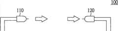
100:超音波系统100: Ultrasonic system
110:超音波传送器110: Ultrasonic Transmitter
120:超音波接收器120: Ultrasonic receiver
200:同步脉冲200: sync pulse
300:资料脉冲300: data pulse
具体实施方式Detailed ways
本发明提出一种超音波系统及其通讯方法,利用超音波系统本身具有的超音波收发功能,并透过规范的飞行时间窗口及信息窗口来达成具有通讯功能且低成本的超音波系统。The present invention proposes an ultrasonic system and its communication method, which utilizes the ultrasonic sending and receiving function of the ultrasonic system itself, and realizes a low-cost ultrasonic system with a communication function through standardized flight time windows and information windows.
请同时参照图1及图2,图1绘示依照本发明较佳实施例的超音波系统的示意图,图2绘示依照本发明较佳实施例的超音波系统的波形图。于图1中,超音波系统100包括一超音波传送器110及一超音波接收器120。超音波传送器110耦接至对应的前级电路(未绘示于图),超音波接收器120耦接至对应的后级电路(未绘示于图)。超音波传送器110及超音波接收器120可被配置于同一电子装置(例如超音波灯具等),或可分别被配置于不同电子装置,并不限制。Please refer to FIG. 1 and FIG. 2 at the same time. FIG. 1 shows a schematic diagram of an ultrasonic system according to a preferred embodiment of the present invention, and FIG. 2 shows a waveform diagram of the ultrasonic system according to a preferred embodiment of the present invention. In FIG. 1 , the
于图2中,兹举欲传送数据为“101011”为例做说明,然并不限于此。在超音波系统100启动通讯模式后,超音波传送器110会发射一传送信号。此传送信号包括一同步脉冲200及多个数据脉冲300。其中,传送信号实质上为一脉宽调变(pulse width modulation,PWM)信号,同步脉冲200及数据脉冲300分别是由多个脉冲组合而成,且同步脉冲200的宽度PW1大于数据脉冲300的宽度PW2,意即同步脉冲200的脉冲个数较数据脉冲300的脉冲个数多。由图2可以得知,传送信号中的多个数据脉冲实质上对应于欲传送的数据内容,若欲传送数据为“1”,则数据脉冲存在;反之,若欲传送数据为“0”,则不存在数据脉冲。In FIG. 2 , the data to be transmitted is "101011" as an example for illustration, but it is not limited thereto. After the
在开始传送数据脉冲300前,超音波传送器110会先传送同步脉冲200,如上所述,同步脉冲200由较多个脉冲个数所组成,因而其对应所产生的同步回波具有较大的振幅大小,因而超音波接收器120可根据接收到的同步回波的振幅大小来判断该同步回波是否与同步脉冲200相对应,进而判断是否需进入通讯模式。Before starting to transmit the data pulse 300, the
超音波接收器120会在一飞行时间窗口(Time of Flight window)内接收对应于同步脉冲200的同步回波,此飞行时间窗口的时间长度可为超音波传送器110及超音波接收器120间的距离参数。当超音波接收器120在此飞行时间窗口内接收到同步回波时,超音波接收器120判断同步回波的振幅是否大于一第一临界值th1。若同步回波的振幅未大于第一临界值th1,则超音波接收器120会认定所接收的回波并非对应于同步脉冲200的同步回波,因而不会进入通讯模式,意即其不会对后续所接收的回波进行解译的动作。The
若同步回波的振幅大于第一临界值th1,则超音波接收器120会认定所接收的回波为对应于同步脉冲200的同步回波,并进入通讯模式。超音波接收器120紧接着会在一信息窗口(information window)内接收对应于多个数据脉冲300的多个数据回波,每一个数据回波各自对应于一数据窗口(data window)。超音波接收器120对此些数据回波进行解译的动作。超音波接收器120会判断数据回波的振幅是否大于一第二临界值th2。若数据回波的振幅大于或等于第二临界值th2,超音波接收器120将数据回波解译为数据“1”。若数据回波的振幅小于第二临界值th2(振幅可能为0),超音波接收器120将数据回波解译为数据“0”。如此一来,解译出来的多笔数据即为一数字信号。此数字信号可对应于一指令,使得超音波接收器120的后级电路执行对应于此指令的动作。If the amplitude of the synchronous echo is greater than the first threshold th1, the
此外,在对于具有多个超音波传送器及多个超音波接收器的应用上,由于当其中一个超音波传送器发出同步脉冲时,所有的超音波接收器皆有可能接收到同步回波,但超音波传送器可能仅欲与部分的超音波接收器进行通讯。因此,此数字信号亦可对应于一识别码,以让超音波接收器120判断超音波传送器110是否为一预设的超音波传送器,若为非预设的超音波传送器,则表示此超音波接收器120并非通讯的对象,因而可忽略信息窗口之后的回波,并结束通讯模式。In addition, for applications with multiple ultrasonic transmitters and multiple ultrasonic receivers, when one of the ultrasonic transmitters sends out a synchronous pulse, all ultrasonic receivers may receive synchronous echoes, But the ultrasonic transmitter may only want to communicate with part of the ultrasonic receivers. Therefore, this digital signal can also correspond to an identification code, so that the
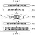
本发明还提供一种超音波系统的通讯方法,此超音波系统包括一超音波传送器及一超音波接收器。请参照图3,其绘示依照本发明较佳实施例的超音波系统的通讯方法的流程图。于步骤S300中,超音波传送器发射一传送信号。其中,传送信号包括一同步脉冲及多个数据脉冲。于步骤S310中,超音波接收器接收同步回波。于步骤S320中,判断同步回波的振幅是否大于一第一临界值。若同步回波的振幅大于第一临界值,则于步骤S330中,超音波接收器接收多个数据回波。之后,于步骤S340中,超音波接收器通过判断数据回波的振幅大小以解译数据回波而得到一数字信号。The invention also provides a communication method of the ultrasonic system, the ultrasonic system includes an ultrasonic transmitter and an ultrasonic receiver. Please refer to FIG. 3 , which shows a flow chart of the communication method of the ultrasonic system according to a preferred embodiment of the present invention. In step S300, the ultrasonic transmitter transmits a transmission signal. Wherein, the transmission signal includes a synchronization pulse and a plurality of data pulses. In step S310, the ultrasonic receiver receives the synchronous echo. In step S320, it is determined whether the amplitude of the synchronous echo is greater than a first threshold. If the amplitude of the synchronous echo is greater than the first threshold, then in step S330, the ultrasonic receiver receives a plurality of data echoes. Afterwards, in step S340, the ultrasonic receiver interprets the data echo by judging the amplitude of the data echo to obtain a digital signal.
上述超音波系统的通讯方法的详细原理已叙述于超音波系统100及其波形图,故于此不再重述。The detailed principle of the communication method of the ultrasonic system has been described in the
本发明上述实施例所揭露的超音波系统及其通讯方法,具有多项优点,以下仅列举部分优点说明如下:The ultrasonic system and its communication method disclosed in the above-mentioned embodiments of the present invention have many advantages, and only some of the advantages are listed below:
本发明的超音波系统及其通讯方法,是通过超音波系统本身具有的超音波收发功能,并透过在规范的飞行时间窗口内接收同步回波及在信息窗口接收多个数据回波,并判断同步回波及数据回波的振幅大小,以辨别所接收的回波是否为事先定义的通讯数据型式,故可以达成具有通讯功能且低成本的超音波系统,使得在此超音波系统中的超音波传送器及超音波接收器可以互相通讯并传递数据,且不须布线即可达到无线收发功能。此外,当此超音波系统应用于超音波灯具时,不用象市面上常见的通讯模块(如蓝芽或WIMAX等)需额外安装才能运作,更具有低成本的优势。The ultrasonic system and its communication method of the present invention, through the ultrasonic sending and receiving function of the ultrasonic system itself, receive synchronous echoes in the standard flight time window and receive multiple data echoes in the information window, and judge Synchronize the amplitude of the echo and data echo to identify whether the received echo is a pre-defined communication data type, so an ultrasonic system with communication functions and low cost can be achieved, so that the ultrasonic system in this ultrasonic system The transmitter and the ultrasonic receiver can communicate with each other and transmit data, and can achieve wireless transceiver function without wiring. In addition, when this ultrasonic system is applied to ultrasonic lamps, it does not require additional installation of communication modules (such as Bluetooth or WIMAX, etc.) common in the market to operate, and it has the advantage of low cost.
综上所述,虽然本发明已以一较佳实施例揭露如上,然其并非用以限定本发明。本发明所属技术领域中具有通常知识者,在不脱离本发明的精神和范围内,当可作各种的更动与润饰。因此,本发明的保护范围当视后附的申请专利范围所界定者为准。In summary, although the present invention has been disclosed as above with a preferred embodiment, it is not intended to limit the present invention. Those skilled in the art of the present invention can make various changes and modifications without departing from the spirit and scope of the present invention. Therefore, the scope of protection of the present invention should be defined by the scope of the appended patent application.
Claims (12)
Priority Applications (2)
| Application Number | Priority Date | Filing Date | Title |
|---|---|---|---|
| CN2009102526627ACN102088320B (en) | 2009-12-03 | 2009-12-03 | Ultrasonic system and communication method thereof |
| US12/840,384US8422337B2 (en) | 2009-12-03 | 2010-07-21 | Ultrasonic system and communication method thereof |
Applications Claiming Priority (1)
| Application Number | Priority Date | Filing Date | Title |
|---|---|---|---|
| CN2009102526627ACN102088320B (en) | 2009-12-03 | 2009-12-03 | Ultrasonic system and communication method thereof |
Publications (2)
| Publication Number | Publication Date |
|---|---|
| CN102088320A CN102088320A (en) | 2011-06-08 |
| CN102088320Btrue CN102088320B (en) | 2013-10-30 |
Family
ID=44081881
Family Applications (1)
| Application Number | Title | Priority Date | Filing Date |
|---|---|---|---|
| CN2009102526627AExpired - Fee RelatedCN102088320B (en) | 2009-12-03 | 2009-12-03 | Ultrasonic system and communication method thereof |
Country Status (2)
| Country | Link |
|---|---|
| US (1) | US8422337B2 (en) |
| CN (1) | CN102088320B (en) |
Families Citing this family (20)
| Publication number | Priority date | Publication date | Assignee | Title |
|---|---|---|---|---|
| US8509882B2 (en) | 2010-06-08 | 2013-08-13 | Alivecor, Inc. | Heart monitoring system usable with a smartphone or computer |
| US8700137B2 (en) | 2012-08-30 | 2014-04-15 | Alivecor, Inc. | Cardiac performance monitoring system for use with mobile communications devices |
| US9351654B2 (en) | 2010-06-08 | 2016-05-31 | Alivecor, Inc. | Two electrode apparatus and methods for twelve lead ECG |
| US9098865B2 (en)* | 2011-04-07 | 2015-08-04 | Facebook, Inc. | Ultrasonic near-field communication |
| CN103312419B (en)* | 2012-03-07 | 2015-05-20 | 苏州汉朗光电有限公司 | Method and system for data communication based on audio or ultrasonic |
| CN102594461A (en)* | 2012-03-23 | 2012-07-18 | 斯肯威(上海)工业检测科技有限公司 | Combined modulation ultrasonic pulse transceiving method and device |
| US10508937B2 (en) | 2012-04-12 | 2019-12-17 | Texas Instruments Incorporated | Ultrasonic flow meter |
| US9254095B2 (en) | 2012-11-08 | 2016-02-09 | Alivecor | Electrocardiogram signal detection |
| WO2014107700A1 (en) | 2013-01-07 | 2014-07-10 | Alivecor, Inc. | Methods and systems for electrode placement |
| WO2014145927A1 (en) | 2013-03-15 | 2014-09-18 | Alivecor, Inc. | Systems and methods for processing and analyzing medical data |
| US9247911B2 (en) | 2013-07-10 | 2016-02-02 | Alivecor, Inc. | Devices and methods for real-time denoising of electrocardiograms |
| CN104378124A (en)* | 2013-08-16 | 2015-02-25 | 北京千橡网景科技发展有限公司 | Method and device for sending and receiving data with sound |
| US10898076B2 (en) | 2013-09-30 | 2021-01-26 | The Research Foundation For The State University Of New York | Transmission and medium access control techniques for ultrasonic communications in the body |
| US10506927B2 (en)* | 2013-09-30 | 2019-12-17 | The Research Foundation For The State University Of New York | Medium-access control schemes for ultrasonic communications in the body based on second order statistics |
| EP4537748A1 (en) | 2013-12-12 | 2025-04-16 | Alivecor, Inc. | Methods and systems for arrhythmia tracking and scoring |
| ES2820923T3 (en) | 2015-05-13 | 2021-04-22 | Alivecor Inc | Mismatch monitoring |
| JP2017112567A (en)* | 2015-12-18 | 2017-06-22 | 株式会社デンソー | Information providing device and information providing system |
| JP6544447B2 (en)* | 2016-02-18 | 2019-07-17 | 富士電機株式会社 | Signal transmission device |
| CN106850081A (en)* | 2017-02-28 | 2017-06-13 | 深圳市欧唯科技有限公司 | A kind of electronic name card exchange method and system |
| CN110602640A (en)* | 2018-06-12 | 2019-12-20 | 光宝科技股份有限公司 | Wireless communication system, host device, mobile device, and method thereof |
Citations (3)
| Publication number | Priority date | Publication date | Assignee | Title |
|---|---|---|---|---|
| US7310286B1 (en)* | 2005-07-11 | 2007-12-18 | The United States Of America Represented By The Secretary Of The Navy | System for undersea digital acoustic communications |
| CN101202604A (en)* | 2007-08-14 | 2008-06-18 | 深圳市同洲电子股份有限公司 | Method, system and equipment for transmitting and receiving network data |
| CN101399931A (en)* | 2007-09-27 | 2009-04-01 | 奇景光电股份有限公司 | Method and system for scanning channels in digital television |
Family Cites Families (11)
| Publication number | Priority date | Publication date | Assignee | Title |
|---|---|---|---|---|
| JPS4951801A (en) | 1972-09-20 | 1974-05-20 | ||
| US5687200A (en)* | 1995-02-17 | 1997-11-11 | Maxtec International Corporation | System for synchronizing distorted data in a data communication system |
| US6508766B2 (en)* | 2000-01-20 | 2003-01-21 | Kabushiki Kaisha Toshiba | Ultrasound diagnostic apparatus |
| DE50111853D1 (en)* | 2001-07-17 | 2007-02-22 | Cit Alcatel | Monitoring unit for optical burst signals |
| US7058315B2 (en)* | 2001-10-09 | 2006-06-06 | Chiaro Networks Ltd. | Fast decision threshold controller for burst-mode receiver |
| US7218862B2 (en)* | 2002-08-22 | 2007-05-15 | Main Street Ventures Llc | All optical cross routing using decoding systems for optical encoded data symbols |
| US6953434B2 (en)* | 2002-09-24 | 2005-10-11 | Ge Medical Systems Global Technology Company, Llc | Method and apparatus to enhance ultrasound contrast imaging using stepped-chirp waveforms |
| GB0228731D0 (en)* | 2002-12-10 | 2003-01-15 | Trw Ltd | Frequency shift keying radar with ambiguity detection |
| JP4921757B2 (en)* | 2005-09-27 | 2012-04-25 | ルネサスエレクトロニクス株式会社 | IC tag, IC tag system and command execution method thereof |
| US8644934B2 (en)* | 2006-09-13 | 2014-02-04 | Boston Scientific Scimed Inc. | Cardiac stimulation using leadless electrode assemblies |
| US20080179053A1 (en)* | 2007-01-29 | 2008-07-31 | Lawrence Kates | System and method for zone thermostat budgeting |
- 2009
- 2009-12-03CNCN2009102526627Apatent/CN102088320B/ennot_activeExpired - Fee Related
- 2010
- 2010-07-21USUS12/840,384patent/US8422337B2/ennot_activeExpired - Fee Related
Patent Citations (3)
| Publication number | Priority date | Publication date | Assignee | Title |
|---|---|---|---|---|
| US7310286B1 (en)* | 2005-07-11 | 2007-12-18 | The United States Of America Represented By The Secretary Of The Navy | System for undersea digital acoustic communications |
| CN101202604A (en)* | 2007-08-14 | 2008-06-18 | 深圳市同洲电子股份有限公司 | Method, system and equipment for transmitting and receiving network data |
| CN101399931A (en)* | 2007-09-27 | 2009-04-01 | 奇景光电股份有限公司 | Method and system for scanning channels in digital television |
Also Published As
| Publication number | Publication date |
|---|---|
| CN102088320A (en) | 2011-06-08 |
| US20110134725A1 (en) | 2011-06-09 |
| US8422337B2 (en) | 2013-04-16 |
Similar Documents
| Publication | Publication Date | Title |
|---|---|---|
| CN102088320B (en) | Ultrasonic system and communication method thereof | |
| JP5992565B2 (en) | Edge-based communication | |
| EP2763365B1 (en) | Method and device for sending and receiving data | |
| US7800518B2 (en) | Pulse modulation method | |
| CN105375991B (en) | With multiple communications based on edge from part equipment | |
| WO2011062459A3 (en) | Ack/nack transmission method and apparatus therefor | |
| CN111478719B (en) | System and method for configuring an external radar device through high-speed reverse data transmission | |
| WO2018095181A1 (en) | Data transmission method and device | |
| US9397871B2 (en) | Communication devices | |
| US10638294B2 (en) | Bluetooth transmission integrated circuit and associated method | |
| JP5794811B2 (en) | Data transmission apparatus and air conditioner equipped with the same | |
| WO2024165192A1 (en) | Methods for improving an ultra-wideband ranging session, apparatus, vehicle and computer program | |
| US10361838B2 (en) | Two-wire communication interface system | |
| US20140036902A1 (en) | Method, Apparatus, and Logic for Wireless Data Transmission | |
| JP5850025B2 (en) | Wireless communication system, wireless device, antenna side device | |
| JP5327679B2 (en) | Remote control device | |
| CN108184221B (en) | Composite exchange method for zigbee node control data | |
| US9287952B1 (en) | Device and method of controlling wave-based antenna | |
| CN106603112B (en) | Method for wireless multi-machine communication and device for implementing the method | |
| JP5388953B2 (en) | Control and monitoring signal remote transmission system | |
| CN120490976A (en) | Radar module, controller, data transmission system, method, product and vehicle | |
| WO2018095180A1 (en) | Data transmission method, data receiving method and devices | |
| KR20120014529A (en) | Serial communication based sequential / simultaneous communication simultaneous implementation system and method | |
| CN103576894A (en) | Interactive image system and remote controller applicable to the interactive image system | |
| CN103885369A (en) | Vehicle-mounted multi-protocol bus system and implementation method thereof |
Legal Events
| Date | Code | Title | Description |
|---|---|---|---|
| C06 | Publication | ||
| PB01 | Publication | ||
| C10 | Entry into substantive examination | ||
| SE01 | Entry into force of request for substantive examination | ||
| C14 | Grant of patent or utility model | ||
| GR01 | Patent grant | ||
| ASS | Succession or assignment of patent right | Owner name:GUANGBAO SCIENCE + TECHNOLOGY CO., LTD. Free format text:FORMER OWNER: JIANXING ELECTRONIC SCIENCE +. TECHNOLOGY CO., LTD. Effective date:20140627 | |
| C41 | Transfer of patent application or patent right or utility model | ||
| TR01 | Transfer of patent right | Effective date of registration:20140627 Address after:Ruiguang road Taiwan Taipei City Neihu district China No. 392 22 floor Patentee after:Lite-On Technology Corporation Address before:Ruiguang road Taiwan Taipei City Neihu district China No. 392 14 floor Patentee before:Jianxing Electronic Science &. Technology Co., Ltd. | |
| CF01 | Termination of patent right due to non-payment of annual fee | Granted publication date:20131030 Termination date:20151203 | |
| EXPY | Termination of patent right or utility model |