CN102087759B - Traceable medical communication service robot - Google Patents
Traceable medical communication service robotDownload PDFInfo
- Publication number
- CN102087759B CN102087759BCN 201010572555CN201010572555ACN102087759BCN 102087759 BCN102087759 BCN 102087759BCN 201010572555CN201010572555CN 201010572555CN 201010572555 ACN201010572555 ACN 201010572555ACN 102087759 BCN102087759 BCN 102087759B
- Authority
- CN
- China
- Prior art keywords
- communication service
- service robot
- medical
- medical communication
- wireless network
- Prior art date
- Legal status (The legal status is an assumption and is not a legal conclusion. Google has not performed a legal analysis and makes no representation as to the accuracy of the status listed.)
- Expired - Fee Related
Links
- 238000004891communicationMethods0.000titleclaimsabstractdescription108
- 230000005540biological transmissionEffects0.000claimsabstractdescription5
- 230000008859changeEffects0.000claimsdescription8
- 238000000034methodMethods0.000claimsdescription8
- 230000006870functionEffects0.000claimsdescription6
- 230000003247decreasing effectEffects0.000claimsdescription4
- 230000008569processEffects0.000claimsdescription4
- XUIMIQQOPSSXEZ-UHFFFAOYSA-NSiliconChemical compound[Si]XUIMIQQOPSSXEZ-UHFFFAOYSA-N0.000claimsdescription3
- 230000009471actionEffects0.000claimsdescription3
- 230000006835compressionEffects0.000claimsdescription3
- 238000007906compressionMethods0.000claimsdescription3
- 230000035945sensitivityEffects0.000claimsdescription3
- 229910052710siliconInorganic materials0.000claimsdescription3
- 239000010703siliconSubstances0.000claimsdescription3
- JBRZTFJDHDCESZ-UHFFFAOYSA-NAsGaChemical group[As]#[Ga]JBRZTFJDHDCESZ-UHFFFAOYSA-N0.000claimsdescription2
- 229910001218Gallium arsenideInorganic materials0.000claimsdescription2
- 238000001914filtrationMethods0.000claimsdescription2
- 238000009434installationMethods0.000claimsdescription2
- 239000002390adhesive tapeSubstances0.000claims1
- 230000004075alterationEffects0.000claims1
- 230000003287optical effectEffects0.000claims1
- 238000010586diagramMethods0.000description7
- 238000005516engineering processMethods0.000description3
- 238000005034decorationMethods0.000description2
- 238000013461designMethods0.000description2
- 238000012423maintenanceMethods0.000description2
- 238000012986modificationMethods0.000description2
- 230000004048modificationEffects0.000description2
- 238000012545processingMethods0.000description2
- 238000011084recoveryMethods0.000description2
- 230000002411adverseEffects0.000description1
- 230000003750conditioning effectEffects0.000description1
- 238000001514detection methodMethods0.000description1
- 238000011161developmentMethods0.000description1
- 229940079593drugDrugs0.000description1
- 239000003814drugSubstances0.000description1
- 238000012377drug deliveryMethods0.000description1
- 230000008846dynamic interplayEffects0.000description1
- 230000000694effectsEffects0.000description1
- 230000036541healthEffects0.000description1
- 238000002513implantationMethods0.000description1
- 230000010365information processingEffects0.000description1
- 238000011900installation processMethods0.000description1
- 238000012544monitoring processMethods0.000description1
- 230000000474nursing effectEffects0.000description1
- 238000011112process operationMethods0.000description1
Images


Landscapes
- Manipulator (AREA)
Abstract
Description
Translated fromChinese技术领域technical field
涉及无线通信及远程控制。它应用于家庭、公寓、护理机构、治疗中心等需要视频语音交流及物品传递领域。Involves wireless communication and remote control. It is used in homes, apartments, nursing institutions, treatment centers and other fields that require video and voice communication and item delivery.
背景技术Background technique
病人在医疗过程中,如果能和主治医生及医护人员保持很好的沟通十分有利于医护人员及时了解病人的情况,病人也能及时的得到主治医生及医护人员的正确指导。因此良好的沟通与积极良好的医疗密切相关。如果得不到良好的沟通,将对病人造成许多不利影响。尤其住院了的病人更需要与医生进行交流沟通,需要医护人员更加细致的照顾。医护人员是经过专业训练的专业护理者,让医生不断的现场回复来自患者、处于康复期的病人的询问,及电话询问,不利于对这个有限资源的有效利用。目前,医院都是通过护士、医生查房来了解病人的情况。这样一方面加大的护士和医生的工作负担,另一方面这样的查房不能保证主治医生及时的了解病人的情况,尤其当医生在会诊的时候病人就很难联系上医生。特别是在医院下班后,病人与医生就更不可能得到很好的沟通。除此之外,就目前而言简单的药品传递仍需要医护人员亲自送到病人手上,而不是比较自动化的机器人来传递完成。这同样也加大了医务人员的工作强度。During the medical treatment process, if the patient can maintain good communication with the attending doctor and medical staff, it will be very helpful for the medical staff to understand the patient's situation in a timely manner, and the patient can also get the correct guidance from the attending doctor and medical staff in a timely manner. Good communication is therefore closely related to positive and good medical care. Without good communication, it will have many adverse effects on patients. In particular, patients who are hospitalized need to communicate with doctors and need more meticulous care from medical staff. Medical staff are professionally trained nurses. It is not conducive to the effective use of this limited resource for doctors to continuously answer inquiries from patients, patients in recovery, and telephone inquiries on the spot. At present, hospitals use nurses and doctors to make ward rounds to understand the patient's condition. On the one hand, this increases the workload of nurses and doctors. On the other hand, such ward rounds cannot ensure that the attending doctor understands the patient's situation in a timely manner, especially when the doctor is in consultation, it is difficult for the patient to contact the doctor. Especially after get off work in the hospital, it is even more impossible for patients and doctors to communicate well. In addition, for now, simple drug delivery still requires medical staff to deliver it to the patient in person, rather than a more automated robot to complete the delivery. This has also increased the workload of medical staff.
针对以上问题,本发明很好地减轻了医生、医护人员来回查房的工作负担,使用无线收发装置范围内的通讯主机就可以通过安装机器人的摄像头信息并向医疗通信服务机器人发送指令来控制医疗通信服务机器人,该医疗通信服务机器人则根据寻迹探测模块来确定行走路线,如同行驶在铁轨上的火车极大方便了医护人员的控制。通过医护人员的控制,医疗通信服务机器人到达需要到达的地方,与病人进行视频通信,及时了解病人的情况。当医生会诊时或下班后可以通过访问Internet的电脑通过Web浏览器与病人进行视频通话,了解病人的情况。装有医疗用品的机器人可以在医护室的电脑主机或更远的任何一台可以上网的电脑上远程进行遥控操作,可寻迹医疗通信服务机器人完成医疗用品的传递,有效的提高了工作效率,增强了有病人的沟通,促进了病人的康复速度。Aiming at the above problems, the present invention well reduces the workload of doctors and medical personnel to make rounds of the ward. Using the communication host within the range of the wireless transceiver device can control the medical treatment by installing the camera information of the robot and sending instructions to the medical communication service robot. Communication service robot, the medical communication service robot determines the walking route according to the tracking and detection module, just like a train running on rails, which greatly facilitates the control of medical staff. Through the control of medical staff, the medical communication service robot arrives at the place where it needs to go, conducts video communication with the patient, and keeps abreast of the patient's situation. When the doctor consults or after get off work, he can make a video call with the patient through a computer that accesses the Internet through a Web browser, and understand the patient's situation. The robot equipped with medical supplies can be remotely operated on the computer host computer in the medical room or any further computer with Internet access. The traceable medical communication service robot completes the delivery of medical supplies, which effectively improves work efficiency. It enhances the communication with patients and promotes the recovery speed of patients.
发明内容Contents of the invention
本发明的目的在于针对目前医疗领域病人与医护人员的沟通效率不高,医疗物品投递的自动化程度低这一不足,提出了一种可远程控制的可寻迹医疗通信服务机器人。本发明为医护人员和病人提供了一个平台。医护人员通过这个发明装置可以实现通过Internet访问控制机器人,实现与病人的实时通信,以及医疗物品的投递工作,极大的提高了工作效率。The purpose of the present invention is to propose a traceable medical communication service robot that can be controlled remotely, aiming at the inefficiency of communication between patients and medical personnel in the current medical field and the low degree of automation in delivery of medical items. The present invention provides a platform for medical staff and patients. Through this inventive device, medical staff can access and control robots through the Internet, realize real-time communication with patients, and deliver medical items, which greatly improves work efficiency.
本发明是通过以下技术实现的:The present invention is achieved through the following technologies:
一种可寻迹医疗通信服务机器人,其包括用于服务于多位病人的医疗通信服务机器人及远程控制端;所述医疗通信服务机器人经无线网络路由器通过Internet互联网与远程控制端进行通讯;A traceable medical communication service robot, which includes a medical communication service robot and a remote control terminal for serving multiple patients; the medical communication service robot communicates with the remote control terminal through the Internet through a wireless network router;
其特征在于:其还包括一条寻迹线,所述寻迹线铺置在医院走道和病房内或其他运用到所述医疗服务机器人的场所,所述寻迹线是一条与运用场地的地面形成明显色差的胶带线(作为寻迹传感器的反射平面);所述医疗通信服务机器人结构包括摄像头、显示屏、麦克风、音响、舵机模块、MCU控制单元、编码器、解码器、缓冲器、寻迹传感器、USB无线网卡,它们构成本医疗通信服务机器人的主体。It is characterized in that it also includes a tracking line, which is laid in the hospital aisle and ward or other places where the medical service robot is used, and the tracking line is a line formed with the ground of the application site. Tape lines with obvious color difference (as the reflection plane of the tracking sensor); the structure of the medical communication service robot includes a camera, display screen, microphone, audio, steering gear module, MCU control unit, encoder, decoder, buffer, and tracking Trace sensor, USB wireless network card, they constitute the main body of this medical communication service robot.
所述MCU控制单元与USB无线网卡双向连通,并分别连接编码器、解码器和舵机模块,同时寻迹传感器通过信号线连接MCU控制单元,MCU控制单元接受远程控制端发来通过USB无线网卡接收的键盘或鼠标控制信号,控制舵机模块的电机转动,寻迹传感器通过对寻迹线信息的采集发送给MCU控制单元,MCU制单元根据医疗通信服务机器人所处的位置调整舵机模块。The MCU control unit is bidirectionally connected with the USB wireless network card, and is connected to the encoder, decoder and steering gear module respectively, while the tracking sensor is connected to the MCU control unit through the signal line, and the MCU control unit receives the remote control terminal through the USB wireless network card. The received keyboard or mouse control signal controls the rotation of the motor of the steering module, and the tracking sensor sends it to the MCU control unit through the collection of tracking line information, and the MCU control unit adjusts the steering module according to the position of the medical communication service robot.
所述医疗通信服务机器人的舵机模块包括伺服调制芯片、增减速的齿轮组、电位器、直流电机,USB无线网卡接收到远程控制端通过键盘或鼠标发来的指令传送给MCU控制单元, MCU控制单元发出控制信号,控制信号通过伺服调制芯片,获得直流偏置电压。舵机模块内部有一个基准电路,用于产生时钟周期和基准信号,将电位器的电压与直流偏置电压比较,获得电压差输出。电压差的正负输出决定直流电机的正反转。当直流电机(054)转速一定时,通过增减速齿轮组带动电位器旋转,使得电压差变化,直流电机就有了停止与运动。The steering engine module of the medical communication service robot includes a servo modulation chip, a gear set for increasing and decreasing, a potentiometer, and a DC motor. The USB wireless network card receives an instruction sent by the remote control terminal through a keyboard or a mouse and sends it to the MCU control unit. The control unit sends a control signal, and the control signal passes through the servo modulation chip to obtain a DC bias voltage. There is a reference circuit inside the servo module, which is used to generate the clock cycle and reference signal, compare the voltage of the potentiometer with the DC bias voltage, and obtain the voltage difference output. The positive and negative output of the voltage difference determines the positive and negative rotation of the DC motor. When the speed of the DC motor (054) is constant, the potentiometer is driven to rotate through the increasing and decreasing gear set, so that the voltage difference changes, and the DC motor stops and moves.
通过远程控制端的控制,医疗通信服务机器人通过寻迹传感器探索路线,该寻迹传感器是一种一体化反射型光电探测器,其发射器是一个砷化镓红外发光二极管,而接收器是一个高灵敏度,硅平面光电三极管,它们安装在医疗通信服务机器人上,以寻迹线为反射平面,当发光二极管发出的光反射回来时,三极管导通输出低电平,此光电管调理电路简单,工作性能稳定。所述寻迹传感器在医疗通信服务机器人上安装六只,MCU控制单元根据寻迹传感器获取的信息把医疗通信服务机器人直线行进时分成三种状态进行处理:当中间的四只寻迹传感器都检测到寻迹线时,表示该医疗服务机器人正在寻迹线的正上方,这时这四只寻迹传感器的电平值将发生改变,设置在MCU控制单元内的程序探测到这种变化的时候,根据MCU控制单元预先设置的程序对舵机模块进行控制进行,此时控制舵机模块内两电机同速度全速运行(舵机模块内左右各有一电机);当检测到同侧的2只或3只寻迹传感器偏出寻迹线时,说明小车处于微偏状态,这时MCU控制单元监测到这种变化根据预先设定的程序将一个电机速度调慢,另一电机速度调快;当检测到有多个寻迹传感器偏出时,说明小车处于较大的偏离状态,这时MCU控制单元同样根据这种变化根据预先设定的程序把一个电机的速度调至极低,另一电机全速,从而在较短时间内完成路线的调整。Through the control of the remote control terminal, the medical communication service robot explores the route through the tracking sensor, which is an integrated reflective photodetector. Sensitivity, silicon planar phototransistors, they are installed on the medical communication service robot, with the trace line as the reflection plane, when the light emitted by the light-emitting diode is reflected back, the triode is turned on and outputs a low level, the photoelectric control circuit is simple and works Stable performance. Six tracking sensors are installed on the medical communication service robot, and the MCU control unit divides the medical communication service robot into three states for processing according to the information obtained by the tracking sensors: when the four tracking sensors in the middle all detect When the tracking line is reached, it means that the medical service robot is directly above the tracking line. At this time, the level values of the four tracking sensors will change. When the program set in the MCU control unit detects this change , according to the preset program of the MCU control unit, the steering module is controlled. At this time, the two motors in the steering module are controlled to run at full speed at the same speed (there is one motor on the left and right in the steering module); when two motors on the same side or When the 3 tracking sensors deviate from the tracking line, it means that the car is in the state of slight deviation. At this time, the MCU control unit monitors this change and adjusts the speed of one motor slowly and the speed of the other motor according to the preset program; when When multiple tracking sensors are detected to deviate, it means that the car is in a relatively large deviation state. At this time, the MCU control unit also adjusts the speed of one motor to a very low speed according to the preset program according to this change, and the speed of the other motor Full speed, so that the adjustment of the route can be completed in a short time.
通过采用以上寻迹传感器,极大地方便了远程控制端的医护人员对医疗通信服务机器人的控制。拥有寻迹功能的医疗通信服务机器人如同行驶在铁轨上的火车,控制方便自如。这样医护人员十分方便的将医疗通信服务机器人控制到需要到达的地方。医疗人员也可以将装放在物体储放箱中的医疗物品方便的递送给需要递送的病人。By adopting the above tracking sensor, it greatly facilitates the control of the medical communication service robot by the medical staff at the remote control end. The medical communication service robot with tracking function is like a train running on the rails, and it is easy to control. In this way, it is very convenient for medical staff to control the medical communication service robot to the place where it needs to reach. The medical staff can also conveniently deliver the medical articles contained in the object storage box to the patients who need delivery.
所述USB无线网卡与缓冲器进行信号连接,再连接解码器,解码器再分别连接显示屏和音响,USB无线网卡通过无线网络进行收发信息,远程控制端的视频语音信息经缓冲器缓存,再经解码器解析,图像信息在显示屏上予以显示,语音信息则通过音响予以播放;The USB wireless network card is signal-connected with the buffer, and then connected to the decoder, and the decoder is respectively connected to the display screen and the audio system. Decoder analysis, image information is displayed on the display screen, and voice information is played through the audio system;
安装在医疗通信服务机器人上的摄像头和麦克风分别通过驱动层连接编码器,再与USB无线网卡通信连接;摄像头将采集到的图像信息经编码器转换成数字信号,经处理的编码信号同时已经进行了压缩处理,然后编码信号经USB无线网卡推送到Internet上;麦克风将采集到的语音信号同样经编码器将模拟信号转化成数字信号,再通过USB无线网卡传送出去。The camera and microphone installed on the medical communication service robot are respectively connected to the encoder through the driver layer, and then communicated with the USB wireless network card; the camera converts the collected image information into a digital signal through the encoder, and the processed encoded signal has been processed at the same time. After compression processing, the encoded signal is pushed to the Internet through the USB wireless network card; the voice signal collected by the microphone is also converted into a digital signal through the encoder, and then transmitted through the USB wireless network card.
无线路由器安放在医院的Internet服务器上,设置好无线网络路由器的IP,无线网络路由器向无线USB网卡动态分配IP。通过无线路由器的Internet和USB无线网卡,安装在医疗服务机器人上的摄像头采集到的图像信息经编码器转换成数字信号,这里数字信号同时进行了压缩编码,编码信号经USB无线网卡推送到Internet上。处于远程控制端的医护人员经Web浏览器来查看病人的视频语音信息,或通过PDA/智能手机。用户可以根据不同的操作平台,选用不同的控制方式,在计算机上可以采用网页来控制,在智能手持终端上则可以通过编写控制程序来控制。同样远程控制端的摄像头和麦克风采集到的医护人员信息经Internet传送到医院的Internet服务器,再通过无线网络路由器和USB无线网卡发送到医疗通信机务机器人的触摸显示屏显示和语音播放器中播放。The wireless router is placed on the Internet server of the hospital, the IP of the wireless network router is set, and the wireless network router dynamically assigns the IP to the wireless USB network card. Through the Internet and USB wireless network card of the wireless router, the image information collected by the camera installed on the medical service robot is converted into a digital signal by the encoder, where the digital signal is compressed and encoded at the same time, and the encoded signal is pushed to the Internet through the USB wireless network card . The medical staff at the remote control end check the patient's video and voice information through a Web browser, or through a PDA/smart phone. Users can choose different control methods according to different operating platforms. On the computer, they can use the webpage to control, and on the smart handheld terminal, they can control by writing a control program. Similarly, the medical staff information collected by the camera and microphone at the remote control terminal is transmitted to the Internet server of the hospital via the Internet, and then sent to the touch screen display and voice player of the medical communication maintenance robot through the wireless network router and USB wireless network card.
物体储放盒均安装在医疗通信服务机器人上,可以摆放一些药品或其他医疗物品等,通过控制端的键盘命令操作将医疗服务机器人移动到需要送达的病人处。The object storage boxes are all installed on the medical communication service robot, and some medicines or other medical items can be placed, and the medical service robot is moved to the patient to be delivered through the keyboard command operation of the control terminal.
与现有技术相比,本发明采用了point-point/point-multipoint结构,从而非常方便的实现了从Internet远程控制一台或多台医疗通信服务机器人,实现了远程端与医疗通信服务机器人之间的实时语音视频通信。使用了轨迹识别技术,方便了医护人员的控制医疗通信服务机器人的行驶到达需要到达的地方,同样方便了医疗物品的传送。开发端与应用端相互独立,从而方便了系统的维护和升级;监控端为普通浏览器方便了医护人员操作,而该机器人端则使用了Linux平台架构,方便了病人的操作,方便了其他娱乐等程序的植入,降低了用户的使用难度。提供了一个医生与病人、健康与服务之间的平台,使得病人与医生到了更好的实时沟通,同时降低了医护人员的劳动强度,提高了服务质量。Compared with the prior art, the present invention adopts the point-point/point-multipoint structure, thereby realizing the remote control of one or more medical communication service robots from the Internet very conveniently, realizing the communication between the remote terminal and the medical communication service robots. real-time voice and video communication between The trajectory recognition technology is used, which facilitates the medical staff to control the driving of the medical communication service robot to the place where it needs to reach, and also facilitates the delivery of medical items. The development end and the application end are independent of each other, which facilitates the maintenance and upgrading of the system; the monitoring end uses a common browser to facilitate the operation of medical staff, while the robot end uses the Linux platform architecture, which facilitates the operation of patients and other entertainment. The implantation of other programs reduces the difficulty for users to use. It provides a platform between doctors and patients, health and services, enabling better real-time communication between patients and doctors, while reducing the labor intensity of medical staff and improving service quality.
附图说明Description of drawings
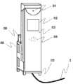
图1 是本可寻迹医疗通信服务机器人的外形正面示意图Figure 1 is a schematic front view of the traceable medical communication service robot
图2 是医疗通信服务机器人的外形背面示意图Figure 2 is a schematic diagram of the back of the medical communication service robot
图3是医疗通信服务机器人的硬件框图Figure 3 is the hardware block diagram of the medical communication service robot
图4是医疗通信服务机器人寻迹传感器的内部工作示意图Figure 4 is a schematic diagram of the internal working of the tracking sensor of the medical communication service robot
图5是医疗通信服务机器人寻迹传感器部分的工作流程示意图Figure 5 is a schematic diagram of the workflow of the tracking sensor part of the medical communication service robot
图6 是医疗通信服务机器人舵机模块与通信及内部工作示意图Figure 6 is a schematic diagram of the servo module, communication and internal work of the medical communication service robot
图7 是医疗通信服务机器人与远程控制端的通信方式及控制原理图Figure 7 is the communication mode and control principle diagram of the medical communication service robot and the remote control terminal
图8 是医疗通信服务机器人具体流程操作示意图。Figure 8 is a schematic diagram of the specific process operation of the medical communication service robot.
具体实施方式Detailed ways
以下结合附图对做详细的说明:The following is a detailed description in conjunction with the accompanying drawings:
本实施在以本发明技术方案为前提条件下进行实施,给出了详细的实施方式和过程,但的保护范围不限于下述的实施例。This implementation is implemented under the premise of the technical solution of the present invention, and detailed implementation methods and processes are given, but the scope of protection is not limited to the following examples.
参见图7, 可寻迹医疗通信服务机器人包括医疗通信服务机器人1及远程控制端2;所述医疗通信服务机器人1经无线网络路由器22通过Internet互联网的WEB服务器、网络控制服务器等与远程控制端2进行通讯。Referring to Fig. 7 , the traceable medical communication service robot includes a medical
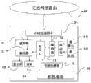
如图1与图3共同所示:医疗通信服务机器人包括摄像头01、显示屏02、麦克风03、音响04、舵机模块05、MCU控制单元11、编码器12、解码器13、缓冲器14、寻迹传感器15 、USB无线网卡21、一种物体储放装置06以及寻迹线3。图中08为该医疗通信服务机器人的一种外观装饰设计。As shown in Figure 1 and Figure 3 together: the medical communication service robot includes a
寻迹线3是一条与运用场地的地面形成明显色差的胶带线,其为寻迹传感器15的反射平面。The
MCU控制单元11与USB无线网卡21双向连通,并分别连接编码器12、解码器13和舵机模块05,同时寻迹传感器15通过信号线连接MCU控制单元11,MCU控制单元11接受远程控制端2发来通过USB无线网卡21接收的键盘或鼠标控制信号,控制舵机模块05的电机转动,寻迹传感器15通过对寻迹线3信息的采集发送给MCU控制单元11,MCU制单元11根据医疗通信服务机器人1所处的位置调整舵机模块05。The
USB无线网卡21与缓冲器14进行信号连接,再连接解码器13,解码器13再分别连接显示屏02和音响04,USB无线网卡21通过无线网络进行收发信息,远程控制端2的视频语音信息经缓冲器14缓存,再经解码器13解析,图像信息在显示屏02上予以显示,语音信息则通过音响04予以播放;USB
安装在医疗通信服务机器人1上的摄像头01和麦克风03分别通过驱动层连接编码器12,再与USB无线网卡21通信连接;摄像头01将采集到的图像信息经编码器12转换成数字信号,经处理的编码信号同时已经进行了压缩处理,然后编码信号经USB无线网卡21推送到Internet上;麦克风03将采集到的语音信号同样经编码器12将模拟信号转化成数字信号,再通过USB无线网卡传送出去。The
当医疗通信服务机器人接收到远程端通过电脑或PDA发来的行动指令(前进/倒退/停止),该医疗通信服务机器人将自动根据寻迹传感器的识别路线加速、减速、转向等,从而实现了远程控制端的简单控制。通过无线网络,USB无线网卡进行收发信息,远程控制端的视频语音信息经缓存器缓存,再经解码器解码,图像信息在显示屏上予以显示,语音信息则通过音响予以播放。安装在医疗通信服务机器人上的摄像头采集到的病人或环境图像信息经编码器转换成数字信号,数字信号同时进行了H.264编码,H.264的编码信号经USB无线网卡推送到Internet上,经麦克风采集到的语音信号同样经编码器将模拟信号转化成数字信号,再通过USB无线网卡传送出去。When the medical communication service robot receives the action command (forward/backward/stop) sent by the remote terminal through the computer or PDA, the medical communication service robot will automatically accelerate, decelerate, turn, etc. according to the identification route of the tracking sensor, thus realizing Simple control from the remote console. Through wireless network, USB wireless network card to send and receive information, the video and voice information of the remote control terminal is cached by the buffer, and then decoded by the decoder, the image information is displayed on the display screen, and the voice information is played through the audio system. The patient or environment image information collected by the camera installed on the medical communication service robot is converted into a digital signal by the encoder, and the digital signal is encoded by H.264 at the same time, and the H.264 encoded signal is pushed to the Internet through the USB wireless network card. The voice signal collected by the microphone is also converted from the analog signal into a digital signal by the encoder, and then transmitted through the USB wireless network card.
如图2所示:本医疗通信服务机器人的背面可见一把柄装置09,该装置是为了能在该医疗通信机器人寻迹错误,或者发生其他故障时可以通过该装置,将该医疗通信服务机器人推至需要提供视频通信服务的地方。以实现其无线视频通信功能。图中08也为该医疗通信服务机器人的一种外观装饰设计。As shown in Figure 2: a handle device 09 can be seen on the back of the medical communication service robot. To the place where video communication service needs to be provided. In order to realize its wireless video communication function. 08 in the figure is also an exterior decoration design of the medical communication service robot.
如图4所示:该寻迹传感器是一种一体化反射型光电探测器15,其发射器152是一个砷化镓红外发光二极管,该红外发光管最大正向电流50mA,而接收器153是一个高灵敏度、硅平面光电三极管,该三极管的发射极-集电极极限电电压为4.5V。寻迹线3即作为寻迹传感器的反射平面151,当发光二极管发出的光经反射平面151反射回来时,光电三极管导通输出低电平。安装过程中需要注意将寻迹传感器安装在距离反射平面15-16mm以内位置,以便很好的接收反射光。此光电管调理电路简单,工作性能稳定。As shown in Figure 4: the tracking sensor is an integrated
如图5所示:医疗通信服务机器人寻迹传感器信息处理过程如下:把医疗通信服务机器人直线行进时分成三种状态,当部分寻迹传感器(中间的四个寻迹传感器,共装置了六个寻迹传感器)都检测到寻迹线时,表示该医疗通信服务机器人正在寻迹线的正上方,此时这四只寻迹传感器的电平值将发生变化,根据不同的电平值MCU控制单元根据已经编写入的程序控制舵机模块内的两个电机同速度全速运行。当检测到同侧的2个或3个传感器偏出寻迹线时,MCU控制单元判断小车处于微偏状态,这时将一侧电机速度调慢,另一侧电机速度调快。当检测到有3个以上寻迹传感器偏出时,MCU控制单元判断小车处于较大的偏离状态,这时MCU控制单元根据预先设定的程序将一个电机的速度调至极低,另一电机全速,从而在较短时间内完成路线的调整。As shown in Figure 5: the information processing process of the tracking sensor of the medical communication service robot is as follows: the medical communication service robot is divided into three states when it travels in a straight line. Tracking sensors) all detect the tracking line, which means that the medical communication service robot is right above the tracking line. At this time, the level values of the four tracking sensors will change, and the MCU controls the The unit controls the two motors in the servo module to run at the same speed and at full speed according to the programmed program. When it is detected that two or three sensors on the same side deviate from the tracking line, the MCU control unit judges that the car is in a slightly biased state, and at this time, the speed of the motor on one side is slowed down, and the speed of the motor on the other side is speeded up. When it is detected that more than three tracking sensors deviate, the MCU control unit judges that the car is in a large deviation state. At this time, the MCU control unit adjusts the speed of one motor to extremely low according to the preset program, and the other motor Full speed, so that the adjustment of the route can be completed in a short time.
如图6所示:所述舵机模块05包括伺服调制芯片051、电位器052、增减速齿轮组053、直流电机054等,所述舵机模块05包括伺服调制芯片051、电位器052、直流电机054、增减速齿轮组053,MCU控制单元11的控制端连接伺服调制芯片051,伺服调制芯片051和电位器052通过电压比较后,与直流电机054连接,直流电机054再连接增减速齿轮组053, 同时电位器052也与增减速齿轮组053连接。上端的USB无线网卡21接收到远程控制端2发来的控制医疗通信服务机器人1前后行动的指令传送给MCU控制单元11,MCU控制单元11再输出控制信号, 控制信号通过伺服调制芯片051,获得直流偏置电压,舵机模块内部有一个基准电路,用于产生时钟周期和基准信号,将电位器052的电压与直流偏置电压比较,获得电压差;电压差的正负输出到直流电机的驱动芯片决定直流电机054的正反转;当直流电机054转速一定时,通过增减速齿轮组053带动电位器052旋转,使得电压差开始变化,直流电机054也就有了停止与运动。通过对电机的控制以实现医疗通信服务机器人的前进、后退、停止。As shown in Figure 6: the
如图7所示:医疗通信服务机器人与远程控制端的通信系统结构大体上可以分为三大部分:远程客户端、无线传输部分、机器人服务端。医护人员在远程控制端可以利用网络控制服务器提供的接口对机器人进行控制。同过Web查看病人的视频信息。客户端即用户的操作平台,它一般指一台可以联网的计算机,或者是PDA/智能手机。在智能手持终端上则需要通过编写控制程序来控制。无线传输部分主要包括无线网络路由器及USB无线网卡,无线路由器安放在医院的Internet服务器上,设置好路由器的IP,无线网络路由器向无线USB网卡动态分配IP。通过无线网络路由器的Internet和USB无线网卡的相互通信,实现远程控制端与医疗通信服务机器人之间的相互通信。机器人服务端由机器人网络控制服务器和Web控制服务器,机器人网络控制服务器采用Socket通信的方式与用户进行交互,实现对医疗通信服务机器人的控制,Web控制服务器采用Web技术,通过CGI程序完成对用户端的动态交互,这样医疗人员就可以通过Web网页来观察医疗通信服务机器人的运行状态以及摄像头和麦克风所采集的病人的视频语音信息。As shown in Figure 7: the communication system structure between the medical communication service robot and the remote control terminal can be roughly divided into three parts: the remote client, the wireless transmission part, and the robot server. Medical staff can use the interface provided by the network control server to control the robot at the remote control end. Check the patient's video information through the Web. The client is the user's operating platform, which generally refers to a computer that can be connected to the Internet, or a PDA/smart phone. On the smart handheld terminal, it needs to be controlled by writing a control program. The wireless transmission part mainly includes a wireless network router and a USB wireless network card. The wireless router is placed on the Internet server of the hospital, and the IP of the router is set. The wireless network router dynamically assigns the IP to the wireless USB network card. Through the mutual communication between the Internet of the wireless network router and the USB wireless network card, the mutual communication between the remote control terminal and the medical communication service robot is realized. The robot server consists of a robot network control server and a Web control server. The robot network control server uses Socket communication to interact with users to realize the control of medical communication service robots. The Web control server uses Web technology to complete the user terminal through CGI programs. Dynamic interaction, so that medical personnel can observe the operating status of the medical communication service robot and the patient's video and voice information collected by the camera and microphone through the Web page.
如图8所示:医疗通信服务机器人具体操作流程如下:医护人员在远程端通过访问Web浏览器,远程控制端是指任何一台可以联网的计算机或手持智能终端,远程控制端可以在医院医护人员工作室、可以在医护人员家中。病人通过对医疗服务机器人的操作,进行呼叫请求操作,启动摄像头和麦克风,USB无线网卡将采集到的信息传送到无线网络路由器,无线网络路由器再将信息推送到Internet,远程端的医护人员便可以查看病人信息,及医疗服务机器人的运动信息。同样远程控制端的发出的指令经Internet传送到无线路由器,再经USB无线网卡发送给医疗通信服务机器人,医疗通信服务机器人执行相应的命令,将医疗通信服务机器人移动到需要到达的地方。远程控制端医护人员的视频语音信息同样经Internet传送到无线路由器,USB无线网卡接收到信号后解码器进行解析,这样病人同样可以看见医护人员的图像语音信息。双方构成了视频语音通信。As shown in Figure 8: The specific operation process of the medical communication service robot is as follows: the medical personnel access the Web browser at the remote end, and the remote control end refers to any computer or handheld smart terminal that can be connected to the Internet. Staff studio, can be in the home of medical staff. By operating the medical service robot, the patient performs a call request operation, starts the camera and microphone, and the USB wireless network card transmits the collected information to the wireless network router, and the wireless network router pushes the information to the Internet, and the medical staff at the remote end can view it. Patient information, and movement information of medical service robots. Similarly, the commands sent by the remote control terminal are transmitted to the wireless router via the Internet, and then sent to the medical communication service robot through the USB wireless network card. The medical communication service robot executes the corresponding command and moves the medical communication service robot to the place where it needs to reach. The video and voice information of the medical staff at the remote control terminal is also transmitted to the wireless router via the Internet. After the USB wireless network card receives the signal, the decoder analyzes it, so that the patient can also see the image and voice information of the medical staff. The two parties constitute a video voice communication.
本发明中,MCU控制单元11选择基于32位RISC体系结构的微处理器,并嵌入Linux操作系统,便于USB无线网卡21的驱动安装及病人对显示屏操作,实现视频语音通信。In the present invention, the
无线USB网卡21是符合802.11b及802.11g协议的无线收发系统,其最大传输速率54Mbps,远程控制端2的语音视频信号通过Internet将信号传送到医院设有IP的无线网络路由器22,无线网络路由器22将收集到的语音视频信号广播出去,医疗通信服务机器人1与远程控制端2建立连接后即可进行视频交流,压缩后的视频流为2Mbps左右。The wireless
无线网络路由器22连接医院内的网络服务设备,它支持xdsl/cable形式接入,支持动态IP分配、支持dhcp服务、mac地址过滤功能,工作在2.4G免费频段,支持802.11b/802.11g协议, 无线网络路由器22与支持加密功能的USB无线网卡21相互配合,可加密传输数据,使他人很难中途窃取信息。The
显示屏02使用触摸显示屏,以方便病人的操作使用,通过触摸显示屏可以看见医护人员的图像信息。The
上述说明的具体实施方式仅为的一种优先实施方式,但是不限于此,在本技术原理基础上的任何形式的修改,例如将应用于无线视频通信机器人等。因此凡照本原理所作修改,或其他等效的置换方式,都包含在的保护范围内。The specific implementation described above is only a preferred implementation, but it is not limited thereto. Any form of modification based on the technical principle will be applied to wireless video communication robots, etc., for example. Therefore, all modifications made according to this principle, or other equivalent replacement methods, are included in the scope of protection.
Claims (7)
Priority Applications (1)
| Application Number | Priority Date | Filing Date | Title |
|---|---|---|---|
| CN 201010572555CN102087759B (en) | 2010-12-03 | 2010-12-03 | Traceable medical communication service robot |
Applications Claiming Priority (1)
| Application Number | Priority Date | Filing Date | Title |
|---|---|---|---|
| CN 201010572555CN102087759B (en) | 2010-12-03 | 2010-12-03 | Traceable medical communication service robot |
Publications (2)
| Publication Number | Publication Date |
|---|---|
| CN102087759A CN102087759A (en) | 2011-06-08 |
| CN102087759Btrue CN102087759B (en) | 2013-01-09 |
Family
ID=44099543
Family Applications (1)
| Application Number | Title | Priority Date | Filing Date |
|---|---|---|---|
| CN 201010572555Expired - Fee RelatedCN102087759B (en) | 2010-12-03 | 2010-12-03 | Traceable medical communication service robot |
Country Status (1)
| Country | Link |
|---|---|
| CN (1) | CN102087759B (en) |
Cited By (1)
| Publication number | Priority date | Publication date | Assignee | Title |
|---|---|---|---|---|
| WO2020258291A1 (en)* | 2019-06-28 | 2020-12-30 | 西门子股份公司 | Method and device for transmitting task execution record, and computer-readable storage medium |
Families Citing this family (20)
| Publication number | Priority date | Publication date | Assignee | Title |
|---|---|---|---|---|
| CN103024030A (en)* | 2012-12-10 | 2013-04-03 | 上海交通大学 | Robot remote control system for coping bandwidth limitation based on wide area network |
| CN104090571A (en)* | 2014-04-15 | 2014-10-08 | 黄河科技学院 | Intelligent detection trolley |
| CN105182882B (en)* | 2015-01-24 | 2016-11-30 | 深圳亿维锐创科技股份有限公司 | A kind of robot system for ward data acquisition |
| WO2017214954A1 (en)* | 2016-06-16 | 2017-12-21 | 深圳市创客工场科技有限公司 | Servo |
| CN106773950A (en)* | 2016-12-13 | 2017-05-31 | 安徽乐年健康养老产业有限公司 | A kind of intelligence patrols the control method of room and dispensing |
| CN106682403A (en)* | 2016-12-13 | 2017-05-17 | 安徽乐年健康养老产业有限公司 | Medical inspection assisting device |
| CN107024934B (en)* | 2017-04-21 | 2023-06-02 | 山东大学 | A hospital service robot and method based on cloud platform |
| CN107127769A (en)* | 2017-06-06 | 2017-09-05 | 佛山市建金建电子科技有限公司 | A kind of robot with videophone |
| CN108512468A (en)* | 2018-04-09 | 2018-09-07 | 重庆东渝中能实业有限公司 | Driving device and driving control system |
| CN108986881A (en)* | 2018-07-12 | 2018-12-11 | 上海常仁信息科技有限公司 | A kind of medication alert system based on robot |
| JP6849769B2 (en)* | 2018-12-20 | 2021-03-31 | キヤノン株式会社 | Communication equipment, communication methods, robot equipment, production equipment, article manufacturing methods, transmission equipment, control programs and recording media |
| CN110653830A (en)* | 2019-09-03 | 2020-01-07 | 南京美桥信息科技有限公司 | Automatic distribution robot system oriented to medical environment |
| CN110794850A (en)* | 2019-12-09 | 2020-02-14 | 攀枝花学院 | A robot tracking control circuit |
| CN111710395A (en)* | 2020-02-11 | 2020-09-25 | 无锡识凌科技有限公司 | Intelligent medical information application system |
| CN112000020A (en)* | 2020-08-07 | 2020-11-27 | 深圳市欧瑞博科技股份有限公司 | Equipment distribution network processing method, equipment distribution network processing device and intelligent panel |
| CN112216358A (en)* | 2020-09-03 | 2021-01-12 | 湖北工程学院 | Medical terminal system, medical terminal and medical platform |
| CN112061176A (en)* | 2020-09-18 | 2020-12-11 | 株洲中车时代电气股份有限公司 | Remote control method for train display |
| CN112220609B (en)* | 2020-10-16 | 2022-06-14 | 江西智诚健康科技有限公司 | Intelligence uterus warming is precious based on portal inserts |
| CN114603570A (en)* | 2020-12-08 | 2022-06-10 | 山东新松工业软件研究院股份有限公司 | Remote monitoring robot |
| CN114376831A (en)* | 2021-12-16 | 2022-04-22 | 中国人民解放军第三〇五医院 | Multifunctional integrated intelligent nursing car based on 5G remote control |
Family Cites Families (6)
| Publication number | Priority date | Publication date | Assignee | Title |
|---|---|---|---|---|
| US6925357B2 (en)* | 2002-07-25 | 2005-08-02 | Intouch Health, Inc. | Medical tele-robotic system |
| CN2685027Y (en)* | 2003-06-30 | 2005-03-16 | 哈尔滨工程大学 | Remote-control nurse assistant robot |
| US8390694B2 (en)* | 2007-02-02 | 2013-03-05 | Koninklijke Philips Electronics N.V. | Medical video communication systems and methods |
| EP1958738B1 (en)* | 2007-02-13 | 2013-08-14 | Abb Research Ltd. | Remote diagnostic system for robots |
| CN201578362U (en)* | 2009-11-23 | 2010-09-15 | 苏州百源软件设计有限公司 | Household remote health-care robot with network and medical instrument data acquisition function |
| CN101862245A (en)* | 2010-05-28 | 2010-10-20 | 上海市古美高级中学 | Hospital service robot |
- 2010
- 2010-12-03CNCN 201010572555patent/CN102087759B/ennot_activeExpired - Fee Related
Cited By (1)
| Publication number | Priority date | Publication date | Assignee | Title |
|---|---|---|---|---|
| WO2020258291A1 (en)* | 2019-06-28 | 2020-12-30 | 西门子股份公司 | Method and device for transmitting task execution record, and computer-readable storage medium |
Also Published As
| Publication number | Publication date |
|---|---|
| CN102087759A (en) | 2011-06-08 |
Similar Documents
| Publication | Publication Date | Title |
|---|---|---|
| CN102087759B (en) | Traceable medical communication service robot | |
| CN101084817B (en) | Opening intelligent calculation frame household multifunctional small-sized service robot | |
| CN204631493U (en) | Controlled endpoints with multi-factor authentication | |
| CN105078450B (en) | A kind of health service robot of achievable brain electro-detection | |
| CN105082149B (en) | A kind of health service robot of achievable blood oxygen saturation detection | |
| CN105094133B (en) | A kind of health service robot based on multifunctional intellectual electronic medicine box | |
| CN101370096A (en) | Interactive television remote control based on spacing positioning | |
| CN204971277U (en) | Can realize health service robot of brain electric -examination survey | |
| CN107450332A (en) | Information transferring method, system, intelligent appliance, control terminal and storage medium | |
| KR20120116134A (en) | Computing device with robotic functions and operating method for the same | |
| CN206614552U (en) | A multifunctional remote inspection service robot | |
| CN106790628A (en) | Smart home house keeper central control system and its control method with body-sensing function | |
| CN106782559A (en) | Smart home house keeper central control system and its control method with telecommunication control | |
| CN108710833B (en) | User identity authentication method and mobile terminal | |
| CN202753154U (en) | Robot device for interaction | |
| CN105139626A (en) | Multifunctional universal remote controller | |
| CN103513770A (en) | Man-machine interface equipment and man-machine interaction method based on three-axis gyroscope | |
| CN108919711A (en) | A kind of remote information interactive system based on built-in Linux | |
| CN206322074U (en) | A kind of automatic pivot structure of notebook computer | |
| CN208930273U (en) | A kind of detachable robot | |
| CN203164866U (en) | Man-machine interaction equipment based on body feelings | |
| CN204971307U (en) | Can realize blood oxygen saturability detection's health service robot | |
| CN204374642U (en) | A kind of Smart Home robot | |
| TW201006635A (en) | In situ robot which can be controlled remotely | |
| CN106535046A (en) | Handle |
Legal Events
| Date | Code | Title | Description |
|---|---|---|---|
| C06 | Publication | ||
| PB01 | Publication | ||
| C10 | Entry into substantive examination | ||
| SE01 | Entry into force of request for substantive examination | ||
| C14 | Grant of patent or utility model | ||
| GR01 | Patent grant | ||
| CF01 | Termination of patent right due to non-payment of annual fee | Granted publication date:20130109 Termination date:20151203 | |
| EXPY | Termination of patent right or utility model |