CN102085119B - Navigation equipment for femoral medullary cavity cutting operation by femoral myelocavity file - Google Patents
Navigation equipment for femoral medullary cavity cutting operation by femoral myelocavity fileDownload PDFInfo
- Publication number
- CN102085119B CN102085119BCN201110054194XACN201110054194ACN102085119BCN 102085119 BCN102085119 BCN 102085119BCN 201110054194X ACN201110054194X ACN 201110054194XACN 201110054194 ACN201110054194 ACN 201110054194ACN 102085119 BCN102085119 BCN 102085119B
- Authority
- CN
- China
- Prior art keywords
- femoral
- sampling points
- cavity
- probe
- medullary cavity
- Prior art date
- Legal status (The legal status is an assumption and is not a legal conclusion. Google has not performed a legal analysis and makes no representation as to the accuracy of the status listed.)
- Expired - Fee Related
Links
Images


Landscapes
- Surgical Instruments (AREA)
- Prostheses (AREA)
Abstract
Translated fromChinese
Description
Translated fromChinese技术领域technical field
本发明涉及一种医用导航设备,尤其是一种用于髋关节置换手术过程中髓腔锉切削股骨腔的导航设备。The invention relates to a medical navigation device, in particular to a navigation device used for cutting a femoral cavity with a medullary cavity rasp during hip joint replacement surgery.
背景技术Background technique
在人体髋关节置换手术过程中,需要采用髓腔锉切除股骨近端股骨颈基底部处部分松质骨以便于植入髋关节股骨柄假体。在采用定制型股骨柄假体的髋关节置换手术中,要求髋关节股骨柄假体与患者股骨腔尽可能地密贴匹配,因此,在加工出一个定制型股骨柄假体的同时,会同时定制出一个相应的髓腔锉,用于切削股骨近端松质骨,这个髓腔锉匹配区域略小于股骨柄假体相应的匹配区域,这样,可通过挤压手术余下的松质骨达到股骨柄假体与患者髓腔的密贴。目前,在髋关节置换手术过程中,手术医生完全凭经验来确定髓腔锉的切削导路。在一些髋关节置换手术中,由于髓腔锉切削导路中心线与患者股骨腔中心线的偏差,导致股骨柄假体无法植入到位,甚至导致患者股骨骨裂现象。当假体无法植入到位时,通常需要对手术部位拍摄X光片来确定股骨柄假体卡死情况,这不仅大大增加了手术时间,而且使患者再次遭受X光的辐射伤害。随后取出卡住的股骨柄假体,再根据股骨柄假体卡住情况,再锉掉患者股骨近端部分松质骨以便于植入股骨柄假体,这会大大降低股骨近端髓腔与髋关节股骨柄假体之间的匹配程度,同时增大股骨柄假体早期松动风险,不利于患者术后的康复。During human hip replacement surgery, it is necessary to use a medullary canal rasp to resect part of the cancellous bone at the base of the femoral neck of the proximal femur to facilitate implantation of the hip femoral stem prosthesis. In hip replacement surgery with custom-made femoral stem prosthesis, it is required that the hip femoral stem prosthesis and the patient's femoral cavity fit as close as possible. Therefore, when a custom-made femoral stem prosthesis is processed, it will be A corresponding medullary cavity file was customized to cut the proximal femoral cancellous bone. The matching area of this medullary cavity file was slightly smaller than the corresponding matching area of the femoral stem prosthesis. In this way, the remaining cancellous bone could be squeezed to reach the femur The close fit between the stem prosthesis and the patient's medullary cavity. Currently, during hip replacement surgery, surgeons determine the cutting path of the rasp entirely by experience. In some hip replacement operations, due to the deviation between the centerline of the medullary canal rasp cutting guide and the centerline of the patient's femoral cavity, the femoral stem prosthesis cannot be implanted in place, and even the patient's femur fractures. When the prosthesis cannot be implanted in place, it is usually necessary to take X-rays of the operative site to determine the stuckness of the femoral stem prosthesis, which not only greatly increases the operation time, but also makes the patient suffer from X-ray radiation damage again. Then take out the stuck femoral stem prosthesis, and then according to the stuck femoral stem prosthesis, file off the cancellous bone of the patient's proximal femur to facilitate the implantation of the femoral stem prosthesis, which will greatly reduce the distance between the proximal femoral medullary cavity and the femoral stem prosthesis. The degree of matching between the femoral stem prosthesis of the hip joint increases the risk of early loosening of the femoral stem prosthesis, which is not conducive to the postoperative rehabilitation of patients.
发明内容Contents of the invention
本发明的目的在于提供一种协助手术医生确定髓腔锉切削导路,确保定制型股骨柄假体与患者髓腔的匹配程度,提高髋关节股骨柄假体植入的一次成功率的切削导航设备。The purpose of the present invention is to provide a cutting navigation that assists the surgeon in determining the cutting guide of the medullary cavity rasp, ensures the matching degree of the customized femoral stem prosthesis and the patient's medullary cavity, and improves the first-time success rate of hip joint femoral stem prosthesis implantation equipment.
一种用于髓腔锉切削股骨腔手术的导航设备的技术方案是:包括采集单元、中央控制单元、显示单元、按钮键盘、定位板和探棒;该中央控制单元分别与用于采样点位置信息的采集单元、用于显示导路的显示单元和用于控制的按钮键盘相连,该中央控制单元控制采集单元采样点位置信息并计算出切削导路;所述定位板上设有三个采样点,采样点构成直角三角形的三个顶点;探棒的后端中心线上设有两个采样点;髓腔锉打拔器导杆中心线上设有两个采样点。A technical proposal of a navigation device for femoral cavity rasp cutting operation is: comprising an acquisition unit, a central control unit, a display unit, a button keyboard, a positioning board and a probe; The information collection unit, the display unit for displaying the guiding path, and the button keyboard for controlling are connected. The central control unit controls the sampling point position information of the collecting unit and calculates the cutting guiding path; the positioning board is provided with three sampling points , The sampling points constitute three vertices of a right triangle; two sampling points are arranged on the center line of the rear end of the probe; two sampling points are arranged on the center line of the guide rod of the pulp cavity file puller.
本发明的采集单元由触点、触点座、两段杆臂、角度传感器和基座组成,所述触点为球体,固定在触点座上;触点座与其中一段杆臂之间、其中一段杆臂与另一段杆臂之间以及另一段杆臂与基座之间分别采用转动副连接,每个转动副连接处设有角度传感器。The acquisition unit of the present invention is composed of a contact, a contact seat, two sections of lever arms, an angle sensor and a base. The contact is a sphere fixed on the contact seat; One section of the lever arm is connected to the other section of the lever arm and between the other section of the lever arm and the base is respectively connected by a rotary pair, and an angle sensor is provided at the joint of each rotary pair.
本发明的按钮键盘上有9个按钮,其中两个按钮分别用来发出刷新显示单元3上显示的探棒(6)的后端(12)中心线与髓腔锉打拔器导杆(15)中心线指令,另外七个按钮分别用于存储采样点位置信息。There are 9 buttons on the button keyboard of the present invention, two of which are used to send out the center line of the rear end (12) of the probe (6) displayed on the
本发明定位板上的三个采样点、探棒上的两个采样点和髓腔锉打拔器导杆上的采样点都为半球形凹槽,该凹槽直径与触点直径相同。The three sampling points on the positioning plate of the present invention, the two sampling points on the probe rod and the sampling point on the guide rod of the pulp cavity file puller are all hemispherical grooves, and the diameter of the groove is the same as that of the contact point.
作为本发明的进一步改进:采集单元非接触式采集定位设备,所述非接触式采集定位设备由激光、红外线或超声波设备组成。As a further improvement of the present invention: the collection unit is a non-contact collection and positioning device, and the non-contact collection and positioning device is composed of laser, infrared or ultrasonic equipment.
本发明的有益效果:通过采集单元与定位板上的凹槽确定空间的坐标系,通过探棒上的凹槽确定患者股骨髓腔中心线,从而确定骨髓腔中心线与髓腔锉切削导路中心线相对位置关系,并通过调整髓腔锉切削导路,使切削导路中心线尽可能与患者股骨髓腔中心线相重合,提高股骨柄假体一次植入成功率。Beneficial effects of the present invention: the spatial coordinate system is determined by the acquisition unit and the groove on the positioning plate, and the centerline of the femoral medullary canal of the patient is determined by the groove on the probe, thereby determining the centerline of the medullary canal and the cutting guide of the medullary canal file The relative position relationship of the center line, and by adjusting the cutting guide of the medullary cavity rasp, the center line of the cutting guide coincides with the center line of the patient's femoral medullary cavity as much as possible, so as to improve the success rate of one-time implantation of the femoral stem prosthesis.
附图说明Description of drawings
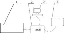
图1为髓腔锉切削股骨腔手术的导航设备示意图;Fig. 1 is the schematic diagram of the navigation equipment for cutting the femoral cavity with the medullary cavity rasp;
图2为采集单元结构示意图;Fig. 2 is a schematic diagram of the structure of the acquisition unit;
图3为定位板结构示意图;Fig. 3 is a structural schematic diagram of a positioning plate;
图4为探棒结构示意图;Figure 4 is a schematic diagram of the probe structure;
图5为探棒上采样点中心处截面结构示意图;Figure 5 is a schematic diagram of the cross-sectional structure at the center of the sampling point on the probe;
图6为改进后髓腔锉打拔器结构示意图;Fig. 6 is a structural schematic diagram of the improved medullary cavity file puller;
图7为改进后髓腔钻结构示意图;Figure 7 is a schematic diagram of the structure of the improved medullary cavity drill;
其中:1-采集单元,2-中央控制单元,3-显示单元,4-按钮键盘,5-定位板,6-探棒,7-触点,8-触点座,9-杆臂,10-角度传感器,11-基座,12-后端;13-前端,14-挡板,15-导杆,16-击打器,17-外伸杆,18-电源开关,19-髓腔钻外壳,20-钻头。Among them: 1-acquisition unit, 2-central control unit, 3-display unit, 4-button keyboard, 5-positioning board, 6-probe, 7-contact, 8-contact seat, 9-lever arm, 10 -Angle sensor, 11-base, 12-rear end; 13-front end, 14-baffle plate, 15-guide rod, 16-hitter, 17-extending rod, 18-power switch, 19-medullary canal drill Housing, 20-bit.
具体实施方式Detailed ways
以下结合附图对本发明作进一歩说明:The present invention will be further described below in conjunction with accompanying drawing:
一种髓腔锉切削股骨腔手术的导航设备的示意图如图1所示,主要包括:采集单元1、中央控制单元2、显示单元3、按钮键盘4;用于采样点位置信息的采集单元1与中央控制单元2相连,中央控制单元2与用于显示导路的显示单元3和用于控制的按钮键盘4分别相连,中央控制单元2控制采集单元1采样点位置信息并计算出切削导路。采集单元1由机械臂组成,如图2所示,主要由触点7、触点座8、两段杆臂9、角度传感器10以及基座11组成,其中触点7为球体,固定在触点座8上。触点座8与其中一段杆臂9之间,其中一段杆臂9与另中一段杆臂9之间以及另中一段杆臂9与基座11之间采用转动副连接,在每个转动副连接处都设有角度传感器10,用以测定各个传动副处相邻构件之间的夹角。A schematic diagram of a navigation device for medullary cavity file cutting femoral cavity surgery is shown in Figure 1, mainly comprising:
导航设备还有作为附件的定位板5,如图3所示,定位板5上有三个安装孔504,505和506,手术中用骨钉将定位板5固定在患者股骨大粗隆处,定位板5应大致与患者股骨中心线垂直。另外,定位板5上设有三个采样点501、502和503,采样点均为半球形凹槽,其直径等于触点7的直径。由这三个采样点501、502和503可以构建出局部坐标系,采样点501为坐标原点,采样点502为局部坐标系X轴上的一点,采样点503为局部坐标系Y轴上的一点,Z轴方向根据右手定则确定。由于定位板5固定在患者股骨上,手术中即便患者腿部位置发生了变动,患者股骨腔中心线在这个局部坐标系中的情况不会发生改变。The navigation device also has a
导航设备还有作为附件的探棒6,如图4所示,主要由后端12和前端13构成,探棒6的后端12和前端13采用螺纹联接,后端12上有一凹槽,凹槽有两个采样点1201和1202,采样点为半球形凹槽,凹槽直径与触点7的直径相同,采样点1201和1202中心处截面形状如图5所示。在确定患者股骨腔中心线时,探棒6的前端13将被插入患者股骨腔,通过采集采样点1201和1202的位置信息,再由这两点构成一条直线,这条直线就为患者股骨腔中心线。The navigation device also has a
如图6所示,髓腔锉打拔器安装在髓腔锉后方,由挡板14、导杆15以及击打器16三部分组成,导杆15中设有两个采样点1501和1502,采样点为半球形凹槽,采样点1501和1502中心处截面形状与探棒6上采样点1201和1202中心处截面形状相同,凹槽直径与触点7直径也相同。通过采集采样点1501和1502位置信息,再由这两点构成一条直线,这条直线就为当前髓腔锉切削导路中心线。As shown in Figure 6, the pulp cavity file puller is installed behind the pulp cavity file and consists of three parts: a
中央控制单元2接受来自采集单元1各转动副处角度传感器10传来的角度信号,处理这些角度信号,并根据触点座8、杆臂9以及基座11各部分尺寸计算出触点7中心相对于基座11中心处的三维坐标值,根据操作指令判定当前触点所处采样点。在本实施例中一共有七个采样点:定位板5上3个采样点,探棒6中心线上2个采样点以及髓腔锉打拔器导杆中心线上2个采样点。中央控制单元2根据操作指令要求将当前采样点位置信息,也就是当前采样点相对于基座11中心处的三维坐标值存储到相应的点位置信息存储空间。当中央控制单元2接收到刷新股骨腔中心线指令时,中央控制单元2根据存储的定位板5上3个采样点位置信息构建一个局部坐标系,再根据存储的探棒6中心线上2个采样点位置信息,在这一局部坐标系中构建出一直线作为模拟的患者股骨中心线,并将模拟的患者股骨腔中心线在局部坐标系的情况以及在局部坐标系三个坐标面上的投影信息发送给显示单元3。当中央控制单元2接收到刷新髓腔锉切削导路中心线指令时,同样中央控制单元2根据存储的定位板上3个采样点位置信息构建一个局部坐标系,再根据存储的髓腔锉打拔器导杆15中心线上两个采样点1501和1502的位置信息在局部坐标系中构建出一直线作为模拟的髓腔锉切削导路中心线,并将模拟的髓腔锉切削导路中心线在局部坐标系的情况以及局部坐标系三个坐标面上的投影信息发送给显示单元3。显示单元3接受中央控制单元2传来的患者股骨腔中心线以及髓腔锉切削导路中心线位置信息,将患者股骨腔中心线以及髓腔锉切削导路中心线在局部坐标系及局部坐标三个坐标面上投影情况显示出来,供手术医生参考,以协助手术医生调整髓腔锉切削导路,使髓腔锉切削导路中心线与患者股骨腔中心线尽可能重合,提高假体植入的一次成功率。按钮键盘4上有9个按钮,除两个按钮分别用来发出刷新显示单元3上显示的股骨腔中心线与髓腔锉切削导路中心线指令外,其余7个按钮发出的信号传给中央控制单元2,分别用来确定当前触点7所处位置,这7个按钮分别对应着定位板5上的三个采样点501、502和503,探棒6中心线上的两个采样点1201和1202,以及髓腔锉打拔器导杆15中心线上的两个采样点1501和1502,中央控制单元2将把当前触点中心坐标值存储到相应的采样点坐标值存储空间中。The
切削导航设备的工作过程与原理为:在髋关节置换手术过程中,当截骨完成,暴露出患者股骨腔后,将定位板5固定在患者股骨大粗隆处,并将探棒6的前端13伸入患者股骨腔内,利用触点7触碰采集定位板5的三个采样点501、502和503,以及探棒6的后端12上的两个采样点1201和1202相对于基座11中心处的三维坐标值,由定位板5三个采样点501、502和503坐标值构成一个局部坐标系,由采样点1201和1202构建出患者股骨腔中心线,敲击按钮键盘4上股骨中心线刷新按钮,在显示单元3上显示出患者股骨腔中心线在局部坐标系中以及在局部坐标系三个坐标面中投影情况。取出探棒6,在患者股骨腔中放入连接着打拔器的髓腔锉,利用采集单元1上的触点触碰采集定位板5三个采样点501、502和503,以及打拔器导杆15上的两个采样点1501和1502相对于基座11中心处的三维坐标值(如果患者腿部未移动,采样点501、502和503位置信息可不采集),同样由定位板5三个采样点501、502和503坐标值构成局部坐标系,由采样点1501和1502构建出髓腔锉切削导路中心线,敲击按钮键盘4上髓腔锉切削导路中心线刷新按钮,在显示单元3上显示出髓腔锉切削导路中心线在局部坐标系中以及在局部坐标系三个坐标面中投影情况。手术医生根据显示单元3上显示出的股骨腔中心线及髓腔锉导路中心线在局部坐标系以及在局部坐标系中投影情况进行判断,如有必要,调整髓腔锉切削导路,重新采集打拔器导杆15上的2上采样点1501和1502相对于基座11中心处的三维坐标值(如果患者腿部位置发生移动,还要采集采样点501、502和503位置信息),敲击按钮键盘4上髓腔锉切削导路中心线刷新按钮,在显示单元3上更新显示局部坐标系中的髓腔锉切削导路中心线以及在局部坐标系三个坐标面中投影。直至显示出的股骨腔中心线和髓腔锉导路中心线尽可能的重合,显示单元3上显示出可以切削的提示为止,这时手术医生就可以放心地用髓腔锉切削患者股骨松质骨层。The working process and principle of the cutting navigation device are as follows: during the hip joint replacement operation, after the osteotomy is completed and the patient's femoral cavity is exposed, the
作为实施例的进一步改进,采用在髓腔钻后方的外伸杆17来替代探棒6来确定患者股骨腔中心线,如图7所示,外伸杆17固定在髓腔钻壳体19上,为一半圆杆件,外伸杆中心线与髓腔钻中心线重合,外伸杆17中心处有两个采样点1701和1702,这两个采样点为半球形凹槽,凹槽直径等于上触点7直径。在髋关节置换手术中,当截骨完成后,将定位板5固定在患者股骨大粗隆处,这时采用髓腔钻对患者股骨腔进行扩髓,扩髓完成后,直接采集外伸杆17中心处采样点1701、1702以及定位板5上的三个采样点位置信息,这时采样点1701和1702的连线即为患者股骨腔中心线,这样就由采样点1701和1702位置信息构建出患者股骨腔中心线,采样点1701、1702以及定位板上的三个采样点位置信息采集成以后,退出髓腔钻,后面的操作步骤与实施例相同。As a further improvement of the embodiment, the
作为实施例的进一步改进,采集单元1可以采用激光、红外线或超声波等设备作为非接触式采集定位设备,通过非接触方式获取采样点位置坐标信息;中央控制单元2主要接受来自点位置信息采集单元1传来的点位置信号,根据操作指令要求,处理接收到的点位置坐标信息,分析出患者股骨髓腔中心线与当前髓腔锉切削导路中心线的相对位置关系,并将分析出的患者股骨髓腔中心线与当前髓腔锉切削导路中心线的相对位置关系信息发送给显示设备3;显示设备3根据中央控制单元2发送来的患者股骨髓腔中心线与当前髓腔锉切削导路中心线的相对位置关系信息,采用视频显示或语音提示或文字提示的方式,将患者股骨髓腔中心线与当前髓腔锉切削导路中心线相对位置关系体现出来,供手术医生参考。As a further improvement of the embodiment, the
Claims (4)
Priority Applications (1)
| Application Number | Priority Date | Filing Date | Title |
|---|---|---|---|
| CN201110054194XACN102085119B (en) | 2011-03-08 | 2011-03-08 | Navigation equipment for femoral medullary cavity cutting operation by femoral myelocavity file |
Applications Claiming Priority (1)
| Application Number | Priority Date | Filing Date | Title |
|---|---|---|---|
| CN201110054194XACN102085119B (en) | 2011-03-08 | 2011-03-08 | Navigation equipment for femoral medullary cavity cutting operation by femoral myelocavity file |
Publications (2)
| Publication Number | Publication Date |
|---|---|
| CN102085119A CN102085119A (en) | 2011-06-08 |
| CN102085119Btrue CN102085119B (en) | 2013-05-08 |
Family
ID=44097286
Family Applications (1)
| Application Number | Title | Priority Date | Filing Date |
|---|---|---|---|
| CN201110054194XAExpired - Fee RelatedCN102085119B (en) | 2011-03-08 | 2011-03-08 | Navigation equipment for femoral medullary cavity cutting operation by femoral myelocavity file |
Country Status (1)
| Country | Link |
|---|---|
| CN (1) | CN102085119B (en) |
Families Citing this family (3)
| Publication number | Priority date | Publication date | Assignee | Title |
|---|---|---|---|---|
| CN103300905A (en)* | 2013-06-21 | 2013-09-18 | 江苏大学 | Distal and proximal positioning combined probe for selecting cutting guide of marrow cavity file |
| CN106214213A (en)* | 2016-08-29 | 2016-12-14 | 胡军 | A kind of ultrasonic femoral myelocavity file being applicable to Wicresoft's artificial full hip-joint replacement |
| CN109620415B (en) | 2019-02-14 | 2024-03-26 | 北京水木天蓬医疗技术有限公司 | Robot-assisted ultrasonic bone power system |
Citations (4)
| Publication number | Priority date | Publication date | Assignee | Title |
|---|---|---|---|---|
| US4672957A (en)* | 1983-10-04 | 1987-06-16 | South African Inventions Development Corporation | Surgical device |
| US5910143A (en)* | 1994-12-16 | 1999-06-08 | Exactech, Inc. | Intramedullary alignment guide tool |
| FR2854563A1 (en)* | 2003-05-05 | 2004-11-12 | Fournitures Hospitalieres Ind | Femoral cutting guide for executing preliminary resection, has transversal channel serving as housing for central medullar rod and provided in axial window defined in space that separates branches elongated from base |
| CN201389080Y (en)* | 2009-02-25 | 2010-01-27 | 清华大学 | Universal Calibration Module for Surgical Navigation Instruments |
Family Cites Families (1)
| Publication number | Priority date | Publication date | Assignee | Title |
|---|---|---|---|---|
| FR2802080B1 (en)* | 1999-12-13 | 2002-03-15 | Jacques Afriat | ASSEMBLY FOR THE PLACEMENT OF A FEMALE HIP PROSTHESIS ROD ON A FEMUR |
- 2011
- 2011-03-08CNCN201110054194XApatent/CN102085119B/ennot_activeExpired - Fee Related
Patent Citations (4)
| Publication number | Priority date | Publication date | Assignee | Title |
|---|---|---|---|---|
| US4672957A (en)* | 1983-10-04 | 1987-06-16 | South African Inventions Development Corporation | Surgical device |
| US5910143A (en)* | 1994-12-16 | 1999-06-08 | Exactech, Inc. | Intramedullary alignment guide tool |
| FR2854563A1 (en)* | 2003-05-05 | 2004-11-12 | Fournitures Hospitalieres Ind | Femoral cutting guide for executing preliminary resection, has transversal channel serving as housing for central medullar rod and provided in axial window defined in space that separates branches elongated from base |
| CN201389080Y (en)* | 2009-02-25 | 2010-01-27 | 清华大学 | Universal Calibration Module for Surgical Navigation Instruments |
Also Published As
| Publication number | Publication date |
|---|---|
| CN102085119A (en) | 2011-06-08 |
Similar Documents
| Publication | Publication Date | Title |
|---|---|---|
| US11950859B2 (en) | Navigation and positioning system and method for joint replacement surgery robot | |
| US12059215B2 (en) | Navigation system and method for joint replacement surgery | |
| US20190388104A1 (en) | Computer-assisted surgery tools and system | |
| JP6144351B2 (en) | System and method for guidance and control of an implant placement device | |
| JP7123031B2 (en) | Systems for robot-assisted revision procedures | |
| EP1841372B1 (en) | Computer-assisted hip joint resurfacing method and system | |
| KR102005751B1 (en) | A tooth implant system comprising a patient-interaction device | |
| US7477926B2 (en) | Methods and apparatuses for providing a reference array input device | |
| US10786311B2 (en) | Apparatus and method for registering facial landmarks for surgical navigation system | |
| US20050182320A1 (en) | Arrangement for ascertaining function-determining geometric parameters of a joint of a vertebrate | |
| EP1706054A1 (en) | Methods, systems, and apparatuses for providing patient-mounted surgical navigational sensors | |
| WO2023178944A1 (en) | Mechanical arm-assisted navigation system for hip joint replacement surgery and surgical system | |
| CN102085119B (en) | Navigation equipment for femoral medullary cavity cutting operation by femoral myelocavity file | |
| CN102151161A (en) | Cutting navigator of femoral cavity medullary cavity file | |
| TWM451110U (en) | Navigation apparatus | |
| JP2025119597A (en) | Computer-assisted navigation for pelvic surgery | |
| CN113952088A (en) | Dual-limb linkage measurement device in direct anterior approach hip arthroplasty |
Legal Events
| Date | Code | Title | Description |
|---|---|---|---|
| C06 | Publication | ||
| PB01 | Publication | ||
| C10 | Entry into substantive examination | ||
| SE01 | Entry into force of request for substantive examination | ||
| C14 | Grant of patent or utility model | ||
| GR01 | Patent grant | ||
| CF01 | Termination of patent right due to non-payment of annual fee | Granted publication date:20130508 Termination date:20160308 | |
| CF01 | Termination of patent right due to non-payment of annual fee |