CN102084043B - Nanofiber manufacturing device - Google Patents
Nanofiber manufacturing deviceDownload PDFInfo
- Publication number
- CN102084043B CN102084043BCN2009801346540ACN200980134654ACN102084043BCN 102084043 BCN102084043 BCN 102084043BCN 2009801346540 ACN2009801346540 ACN 2009801346540ACN 200980134654 ACN200980134654 ACN 200980134654ACN 102084043 BCN102084043 BCN 102084043B
- Authority
- CN
- China
- Prior art keywords
- raw material
- material liquid
- container
- space
- released
- Prior art date
- Legal status (The legal status is an assumption and is not a legal conclusion. Google has not performed a legal analysis and makes no representation as to the accuracy of the status listed.)
- Expired - Fee Related
Links
Images


Classifications
- D—TEXTILES; PAPER
- D01—NATURAL OR MAN-MADE THREADS OR FIBRES; SPINNING
- D01D—MECHANICAL METHODS OR APPARATUS IN THE MANUFACTURE OF ARTIFICIAL FILAMENTS, THREADS, FIBRES, BRISTLES OR RIBBONS
- D01D5/00—Formation of filaments, threads, or the like
- D01D5/0007—Electro-spinning
- D01D5/0061—Electro-spinning characterised by the electro-spinning apparatus
- D01D5/0069—Electro-spinning characterised by the electro-spinning apparatus characterised by the spinning section, e.g. capillary tube, protrusion or pin
- D—TEXTILES; PAPER
- D01—NATURAL OR MAN-MADE THREADS OR FIBRES; SPINNING
- D01D—MECHANICAL METHODS OR APPARATUS IN THE MANUFACTURE OF ARTIFICIAL FILAMENTS, THREADS, FIBRES, BRISTLES OR RIBBONS
- D01D5/00—Formation of filaments, threads, or the like
- D01D5/18—Formation of filaments, threads, or the like by means of rotating spinnerets
- D—TEXTILES; PAPER
- D04—BRAIDING; LACE-MAKING; KNITTING; TRIMMINGS; NON-WOVEN FABRICS
- D04H—MAKING TEXTILE FABRICS, e.g. FROM FIBRES OR FILAMENTARY MATERIAL; FABRICS MADE BY SUCH PROCESSES OR APPARATUS, e.g. FELTS, NON-WOVEN FABRICS; COTTON-WOOL; WADDING ; NON-WOVEN FABRICS FROM STAPLE FIBRES, FILAMENTS OR YARNS, BONDED WITH AT LEAST ONE WEB-LIKE MATERIAL DURING THEIR CONSOLIDATION
- D04H1/00—Non-woven fabrics formed wholly or mainly of staple fibres or like relatively short fibres
- D04H1/40—Non-woven fabrics formed wholly or mainly of staple fibres or like relatively short fibres from fleeces or layers composed of fibres without existing or potential cohesive properties
- D04H1/42—Non-woven fabrics formed wholly or mainly of staple fibres or like relatively short fibres from fleeces or layers composed of fibres without existing or potential cohesive properties characterised by the use of certain kinds of fibres insofar as this use has no preponderant influence on the consolidation of the fleece
- D04H1/4382—Stretched reticular film fibres; Composite fibres; Mixed fibres; Ultrafine fibres; Fibres for artificial leather
- D04H1/43838—Ultrafine fibres, e.g. microfibres
- D—TEXTILES; PAPER
- D04—BRAIDING; LACE-MAKING; KNITTING; TRIMMINGS; NON-WOVEN FABRICS
- D04H—MAKING TEXTILE FABRICS, e.g. FROM FIBRES OR FILAMENTARY MATERIAL; FABRICS MADE BY SUCH PROCESSES OR APPARATUS, e.g. FELTS, NON-WOVEN FABRICS; COTTON-WOOL; WADDING ; NON-WOVEN FABRICS FROM STAPLE FIBRES, FILAMENTS OR YARNS, BONDED WITH AT LEAST ONE WEB-LIKE MATERIAL DURING THEIR CONSOLIDATION
- D04H1/00—Non-woven fabrics formed wholly or mainly of staple fibres or like relatively short fibres
- D04H1/70—Non-woven fabrics formed wholly or mainly of staple fibres or like relatively short fibres characterised by the method of forming fleeces or layers, e.g. reorientation of fibres
- D04H1/72—Non-woven fabrics formed wholly or mainly of staple fibres or like relatively short fibres characterised by the method of forming fleeces or layers, e.g. reorientation of fibres the fibres being randomly arranged
- D04H1/728—Non-woven fabrics formed wholly or mainly of staple fibres or like relatively short fibres characterised by the method of forming fleeces or layers, e.g. reorientation of fibres the fibres being randomly arranged by electro-spinning
Landscapes
- Engineering & Computer Science (AREA)
- Textile Engineering (AREA)
- Mechanical Engineering (AREA)
- Spinning Methods And Devices For Manufacturing Artificial Fibers (AREA)
- Nonwoven Fabrics (AREA)
Abstract
Description
Translated fromChinese技术领域technical field
本发明涉及一种纳米纤维制造装置,更详细地说,涉及一种利用静电纺丝(electrospinning)法制造纳米纤维的技术。The present invention relates to a device for manufacturing nanofibers, and more specifically, relates to a technique for manufacturing nanofibers by using an electrospinning method.
背景技术Background technique
近年来,由于能够容易地制造直径为亚微米尺寸的纤维状物质即纳米纤维,静电纺丝法(电荷感应纺丝法)受到关注。在静电纺丝法中,将在溶剂中分散或溶解有高分子材料的原料液向空中放出。如果在放出时通过高电压使原料液带电,则能够使原料液在空中电延伸而获得纳米纤维。(例如参考专利文献1)In recent years, electrospinning (charge induction spinning) has attracted attention because nanofibers, which are fibrous substances with a diameter of submicron, can be easily produced. In the electrospinning method, a raw material solution in which a polymer material is dispersed or dissolved in a solvent is released into the air. If the raw material liquid is charged with a high voltage during discharge, the raw material liquid can be electrically stretched in the air to obtain nanofibers. (For example, refer to Patent Document 1)
更详细地说,通过电场而带电并被放出到空气中的原料液在空中飞翔期间,溶剂蒸发,原料液的体积减少。另一方面,赋予原料液的电荷不受溶剂蒸发的影响而被维持。由此,随着溶剂的蒸发,原料液的电荷密度增大。不久,原料液内部的排斥方向的库仑力超过原料液的表面张力。此时,产生原料液爆炸性地线状延伸的现象(以下称为静电延伸现象)。这种静电延伸现象在空中连续发生,原料液呈几何级数地细分化为线状,从而形成直径为亚微米尺寸的细小的纤维。More specifically, while the raw material liquid charged by the electric field and released into the air flies in the air, the solvent evaporates and the volume of the raw material liquid decreases. On the other hand, the charge imparted to the raw material solution is maintained without being affected by solvent evaporation. Accordingly, the charge density of the raw material solution increases as the solvent evaporates. Soon, the Coulomb force in the repelling direction inside the raw material liquid exceeds the surface tension of the raw material liquid. At this time, a phenomenon in which the raw material liquid stretches linearly explosively (hereinafter referred to as an electrostatic stretching phenomenon) occurs. This electrostatic stretching phenomenon occurs continuously in the air, and the raw material liquid is geometrically subdivided into lines, thereby forming fine fibers with a diameter of submicron.
又,在专利文献2中,提出了一种从旋转式的容器放出原料液、通过静电纺丝法制造纳米纤维的制造装置。如图9所示,该装置具有喷头102,该喷头102在周壁上具有至少一个推出单元101;以及圆筒状的收集体103,该收集体103将喷头102配置在内部。在喷头102与收集体103之间,通过高压电源104施加有电压,以在喷头102与收集体103之间产生电场。在此状态下,使喷头102旋转。由此,经由管105向喷头102内部供给的原料液106通过电场被从推出单元101的顶端抽出,生成纳米纤维。所生成的纳米纤维堆积在收集体103的内周面上而被收集。In addition,
又,在专利文献3中,提出了使在周壁上贯穿设置有多个细孔的圆筒形的容器旋转、利用其离心力使纳米纤维的原料液从上述细孔放出的技术。在专利文献3中,如图10所示,通过在周壁上具有孔112a的供给管112将纳米纤维的原料液114供给到圆筒状容器111的内部,该容器111在周壁上设有多个细孔113。并且,使容器111旋转,利用其离心力将原料液114从细孔113放出。Also, Patent Document 3 proposes a technique in which a cylindrical container having a plurality of pores penetrating through the peripheral wall is rotated, and a raw material solution of nanofibers is released from the pores by utilizing the centrifugal force thereof. In Patent Document 3, as shown in FIG. 10 , a raw material liquid 114 of nanofibers is supplied to the inside of a cylindrical container 111 through a supply pipe 112 having holes 112 a on the peripheral wall. Pores 113. Then, the container 111 is rotated, and the raw material liquid 114 is discharged from the pores 113 by utilizing the centrifugal force.
又,本发明的发明人等,如专利文献4所示的这样(参考图11),开发了在接地的圆筒状容器121的周围配置环状电极122、在容器121与环状电极122之间施加高电压的技术,并进行了实施。由此,能够在容器121上感应出更大的电荷。由此,即使从容器121的细孔喷出的原料液的喷出量略微变化,也能够向该原料液赋予用于静电延伸现象的足够电荷。因此,能够制造出不含原料原状的高分子物质块的高质量的纳米纤维。Also, the inventors of the present invention have developed a method of disposing a ring-
向容器121的径向呈放射状放出的原料液的前进方向由于与径向大致垂直的方向的气流123而偏转。在偏转的原料液前进目的地配置有接地的鼓124。鼓124由于对环状电极122施加高压电而带电,上述原料液或由其生成的纤维状物质被向鼓124吸引。在容器121与鼓124之间配置有长条状的收集体125。被向鼓124吸引的纤维状物质堆积在沿长度方向传送的收集体125上而被收集。The advancing direction of the raw material liquid discharged radially in the
专利文献1:日本特开2005-330624号公报Patent Document 1: Japanese Patent Laid-Open No. 2005-330624
专利文献2:日本特开2007-532790号公报Patent Document 2: Japanese Patent Laid-Open No. 2007-532790
专利文献3:日本特开2008-31624号公报Patent Document 3: Japanese Patent Laid-Open No. 2008-31624
专利文献4:WO2008-062784号公报Patent Document 4: WO2008-062784 Publication
发明要解决的问题The problem to be solved by the invention
如上述所述,在专利文献2的装置中,纳米纤维的原料液通过设置在圆筒型的容器(喷头102)的周壁上的喷嘴(推出单元101)放出。因此,在电荷集中的喷嘴的顶端部,向原料液赋予足够的电荷。因此,能够比较容易地向原料液赋予产生静电延伸现象所需的足够的电荷。As described above, in the apparatus of
然而,喷头102旋转,通过该旋转,原料液利用离心力从推出单元100放出。此时,由于在推出单元101的内侧存在有大量的原料液,因此该内侧的原料液自身也受到离心力的作用。由于该离心力,经常会一段时间推出大量的原料液,在原料液的放出过程中频繁地发生中断。当发生中断时,产生电荷难以滞留在紧接着从推出单元101放出的原料液中、或者发生液体滞留而电荷难以集中等不良现象。其结果,不易产生原料液的延伸,或者完全不产生原料液的延伸,原料液本身附着在周围的收集体上。However, the
又,在专利文献3的技术中,由于也难以使从各细孔113放出的原料液114的量保持一定,因此会产生同样的问题。Also, in the technique of Patent Document 3, since it is difficult to keep the amount of raw material liquid 114 released from each pore 113 constant, the same problem arises.
即,如图10所示,原料液114从供给管112的孔112a向容器111的内部滴下而被供给。由于原料液114的流动性较低,因此,原料液114以不均匀的厚度堆积在容器111的内周壁上。当内周壁上的原料液114的厚度不均匀时,从细孔113放出的原料液114受到的离心力也不均匀。由此,从各细孔113放出的原料液114的量产生变动,放出会中断,或者会放出预定量以上的原料液114。其结果,赋予原料液114的电荷密度不够。于是,原料液114就那样以不经过静电延伸现象的液滴的状态固化,固化后的块会混入纳米纤维中。That is, as shown in FIG. 10 , the raw material liquid 114 is supplied dropwise from the hole 112 a of the supply pipe 112 into the container 111 . Since the fluidity of the raw material liquid 114 is low, the raw material liquid 114 is deposited on the inner peripheral wall of the container 111 with an uneven thickness. When the thickness of the raw material liquid 114 on the inner peripheral wall is uneven, the centrifugal force received by the raw material liquid 114 discharged from the pores 113 is also uneven. As a result, the amount of the raw material solution 114 released from each pore 113 fluctuates, the discharge is interrupted, or a predetermined amount or more of the raw material solution 114 is released. As a result, the charge density imparted to the raw material solution 114 was insufficient. Then, the raw material liquid 114 solidifies as it is in the state of liquid droplets that do not undergo the electrostatic stretching phenomenon, and the solidified lumps are mixed into the nanofibers.
采用专利文献4的方法时,向容器121的内部供给的原料液的量也会变动。即使该变动在设定的范围内时,被放出的原料液的量也会发生大的变动。并且,容器高速旋转,由旋转产生的离心力和由重力产生的力累加起来作用于容器内的原料液。由此,原料液在容器内变得不均匀。其结果,难以完全防止生成未产生静电延伸现象的状态的原料液块。When the method of Patent Document 4 is adopted, the amount of the raw material liquid supplied to the inside of the
发明内容Contents of the invention
本发明鉴于上述问题而做成,其目的在于,提供一种纳米纤维制造方法及制造装置,能够以较高的生产效率制造高质量的纳米纤维,这种纳米纤维不含有未产生静电延伸现象的状态的原料液块。The present invention is made in view of the above-mentioned problems, and its object is to provide a nanofiber manufacturing method and a manufacturing device capable of manufacturing high-quality nanofibers with high production efficiency. state of raw material liquid block.
用于解决技术问题的手段Means used to solve technical problems
本发明提供一种纳米纤维制造装置,该装置具有:旋转容器,该旋转容器具有导入含有高分子材料的原料液的空间、以及多个孔在外周面上开口的筒状的外周壁,所述多个孔用于利用离心力将所述空间内的原料液向径向外侧放出,所述多个孔和所述空间连通,并且至少所述孔的开口部由导体形成;旋转驱动装置,该旋转驱动装置对所述容器进行旋转驱动;加压装置,该加压装置在原料液填充于所述空间的状态下,对所述空间内的原料液进行加压;电极,该电极在所述容器的周围配设在距离所述外周面一定距离处;电位差赋予装置,该电位差赋予装置向所述容器与所述电极之间赋予电位差,以在所述容器与所述电极之间产生电场;收集装置,该收集装置收集纤维状物质,该纤维状物质由因所述容器上产生的电荷而带电、并从所述孔放出的所述原料液生成;以及偏转装置,该偏转装置使从所述孔向径向外侧放出的原料液或由所述被放出的原料液生成的纤维状物质向与所述旋转容器的旋转轴平行的方向偏转,所述空间包括形成在距离所述周壁的表面一定深度处且径向进深一定的间隙,所述旋转容器的外径在旋转的轴向上直线式变化。The present invention provides a nanofiber manufacturing device, which has: a rotating container having a space for introducing a raw material liquid containing a polymer material; A plurality of holes are used to release the raw material liquid in the space radially outward by centrifugal force, the plurality of holes communicate with the space, and at least the openings of the holes are formed by conductors; the rotating drive device, the rotating The driving device rotates and drives the container; the pressurizing device pressurizes the raw material liquid in the space when the raw material liquid is filled in the space; the electrode is placed in the container The surrounding area is arranged at a certain distance from the outer peripheral surface; the potential difference imparting device applies a potential difference between the container and the electrode to generate a potential difference between the container and the electrode. an electric field; collecting means that collects fibrous matter generated from said raw material liquid that is charged by an electric charge generated on said container and discharged from said hole; and deflecting means that causes The raw material liquid released radially outward from the hole or the fibrous matter generated from the released raw material liquid is deflected in a direction parallel to the rotation axis of the rotary container, and the space includes a space formed at a distance from the peripheral wall. There is a certain depth on the surface of the surface and a certain gap in the radial direction, and the outer diameter of the rotating container changes linearly on the axis of rotation.
发明效果Invention effect
采用本发明,在容器的周壁上设有多个细孔,该容器的内部空间与这些细孔连通,在原料液填充于容器的内部空间的状态下,对该内部空间的原料液进行加压并将其从细孔放出。由此,能够不使原料液中断地放出一定量的原料液。因此,能够使赋予原料液的电荷的密度均匀。其结果,能够更加大量地制造高质量的纳米纤维,该纳米纤维不含有未产生静电延伸现象的状态的原料液块。According to the present invention, a plurality of fine holes are provided on the peripheral wall of the container, and the inner space of the container communicates with these fine holes, and the raw material liquid in the inner space is pressurized while the raw material liquid is filled in the inner space of the container. and release it from the pores. Thereby, a constant amount of raw material liquid can be discharged without interrupting the raw material liquid. Therefore, it is possible to make the density of electric charge imparted to the raw material liquid uniform. As a result, it is possible to produce a larger amount of high-quality nanofibers that do not contain raw material liquid lumps in a state where the electrostatic stretching phenomenon has not occurred.
附图说明Description of drawings
图1是表示本发明实施形态1的纳米纤维制造装置的大致结构的、局部剖开的侧视图。Fig. 1 is a partially cutaway side view showing a schematic structure of a nanofiber manufacturing apparatus according to
图2是表示图1的装置所使用的容器的详细结构的剖视图。Fig. 2 is a cross-sectional view showing a detailed structure of a container used in the apparatus of Fig. 1 .
图3是表示可代替上述容器的其它容器的详细结构的剖视图。Fig. 3 is a sectional view showing a detailed structure of another container which can replace the above-mentioned container.
图4是表示本发明实施形态2的纳米纤维制造装置的大致结构的、局部剖开的侧视图。Fig. 4 is a partially cutaway side view showing a schematic structure of a nanofiber manufacturing apparatus according to
图5是表示本发明实施形态3的纳米纤维制造装置的大致结构的、局部剖开的侧视图。Fig. 5 is a partially cutaway side view showing a schematic structure of a nanofiber manufacturing apparatus according to Embodiment 3 of the present invention.
图6是将图4的装置的变形例局部剖开的侧视图。Fig. 6 is a partially cutaway side view of a modified example of the device of Fig. 4 .
图7是表示本发明实施形态6的纳米纤维制造装置的容器的详细结构的剖视图。Fig. 7 is a cross-sectional view showing the detailed structure of a container of a nanofiber manufacturing apparatus according to Embodiment 6 of the present invention.
图8是表示本发明的实施例和比较例的细孔直径与转速之间的关系的图表。FIG. 8 is a graph showing the relationship between the pore diameter and the rotational speed in Examples and Comparative Examples of the present invention.
图9是表示以往的纳米纤维制造装置的一例的侧视图。Fig. 9 is a side view showing an example of a conventional nanofiber manufacturing apparatus.
图10是表示以往的纳米纤维制造装置的另一例的结构的剖视图。Fig. 10 is a cross-sectional view showing the structure of another example of a conventional nanofiber manufacturing apparatus.
图11是表示以往的纳米纤维制造装置的又一例的侧视图。Fig. 11 is a side view showing still another example of a conventional nanofiber manufacturing apparatus.
符号说明Symbol Description
1纳米纤维制造装置1 Nanofiber manufacturing device
2容器2 containers
2a细孔2a pores
3环状电极3 ring electrodes
4高压电源4 high voltage power supply
5收集器5 collectors
7原料液导入空间7 Raw material liquid introduction space
8旋转接头8 swivel joints
16电动机16 electric motor
19原料液罐19 raw material liquid tank
20原料液泵20 raw material liquid pump
22压力传感器22 pressure sensor
24控制部24 Control Department
26气流26 Airflow
F原料液F raw material liquid
F1纤维状物质F1 Fibrous Matter
具体实施方式Detailed ways
下面,参考附图对本发明的实施形态进行详细说明。Hereinafter, embodiments of the present invention will be described in detail with reference to the drawings.
(实施形态1)(Embodiment 1)
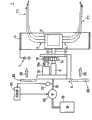
图1表示本发明的实施形态1的纳米纤维制造装置的大致结构的、局部剖开的侧视图。图2是表示容器的详细结构的剖视图。Fig. 1 is a partially cutaway side view showing a schematic structure of a nanofiber manufacturing apparatus according to
制造装置1具有由金属等导体构成的大致圆筒形的容器2。容器2是将原料液F暂时保持在内部空间的结构,该原料液F通过将作为纳米纤维原料的高分子材料分散或溶解在规定的分散剂或溶剂中而形成。在容器2的周壁上形成有多个细孔2a(参考图2),这些细孔2a与容器2的内部空间连通,用于将保持在该空间中的原料液F向外部放出。容器2是以其圆筒形的轴心为中心轴可旋转地被支撑的旋转容器。通过其离心力,将保持在容器2内部空间中的原料液F从细孔2a放出。The
并且,在容器2的周围,同轴地配设有环状电极3,该环状电极3的内周面与容器2的外周面隔开一定的距离并彼此相对,该环状电极3是将长板的长度方向的两端部接合而形成环状的形状。环状电极3与高压电源4的一个端子(在图示的例子中为负极端子)连接。并且,高压电源4的另一个端子(在图示的例子中为正极端子)接地。另一方面,容器2被接地,由此在容器2的外周面、环状电极3的内周面分别感应出极性相反的电荷,在两者之间产生电场。And, around the
从细孔2a放出的原料液F在细孔2a的开口部被赋予电荷。被赋予电荷的原料液F在空中飞翔期间,溶剂蒸发,内部的排斥方向的库仑力增大,连续引起静电延伸现象而被细化为纤维状。这样一来,通过静电延伸现象由原料液F形成纤维状物质F1。The raw material liquid F released from the
这里,细孔2a最好规则地形成在容器2的周壁上。例如,在容器2的轴向上以等间隔排列,在周向上以等间距形成。Here, the
图2表示容器2的详细结构。如图2所示,容器2包括内部具有空间的双重壁结构的圆筒形周壁部11、以及内部具有空间的双重壁结构的圆形壁部12。周壁部11的一端部与圆形壁部12的外周部连接,周壁部11的内部空间与圆形壁部12的内部空间在其连接部分是连通的。而且,连通的这些空间构成导入有原料液的原料液导入空间7。FIG. 2 shows the detailed structure of the
此外,容器2在圆形壁部12的中央安装有原料液供给管13的一端部,该原料液供给管13与圆形壁部12垂直且兼作旋转轴使用。原料液供给管13的管路13a与容器2的原料液导入空间7通过连通孔12b连通,该连通孔12b贯穿设置在圆形壁部12的外侧壁12a的中央。Furthermore, in the
如图1所示,原料液供给管13通过支撑部6被旋转自如地支撑。支撑部6包括旋转接头8和电动机16。原料液供给管13的另一端部与旋转接头8的一端部连接。旋转接头8的另一端部与原料液配管10的一端部连接。原料液供给管13与原料液配管10通过旋转接头8连通。而且,对于原料液供给管13外装有从动齿轮14。从动齿轮14与安装在电动机16的输出轴16a上的主动齿轮18啮合。通过此结构,原料液供给管13通过电动机16的旋转输出而旋转,容器2被旋转驱动。As shown in FIG. 1 , the raw material
原料液配管10的另一端部与原料液罐19连接。而且,在原料液配管10上配设有原料液泵20和压力传感器22。原料液罐19内的原料液F通过原料液泵20经由旋转接头8和原料液供给管13被输送到容器2内。压力传感器22配设在原料液配管10的原料液泵20的下游侧,对原料液泵20的排出压力进行检测,输出与该检测结果相对应的信号。压力传感器22的输出信号被输入控制部24。The other end of the raw material liquid piping 10 is connected to a raw
控制部24根据压力传感器22的检测结果控制原料液泵20,以使原料液泵20的排出压力为规定压力。这里,作为原料液泵20,最好使用内装有压力调节阀的结构,以使含有沸点低的溶剂或分散剂的原料液F能够以一定的压力向容器2供给。而且,作为原料液泵20,最好是通过使用变流器装置,对构成原料液泵20的交流电动机(感应电动机/同步电动机)进行可变速/可变转矩的控制,从而能进行控制的泵。The
通过以上的结构,原料液F通过原料液配管10、旋转接头8及原料液供给管13以规定压力从原料液罐19向容器2的原料液导入空间7供给。由此,原料液导入空间7内的原料液F被加压。With the above configuration, the raw material liquid F is supplied from the raw
而且,如图2所示,容器2的原料液导入空间7,尤其是与细孔2a相对应的部位即周壁部11的内部空间最好形成为径向深度一定,以使从细孔2a放出的原料液F受到的离心力保持一定。由此,原料液利用离心力从细孔放出的放出压力为一定。其结果,可以使原料液的放出量为一定。也就是说,从各个细孔2a放出的原料液F的量不会随时间变化而保持一定,并且从各个细孔2a放出的原料液F的量彼此相等,是均匀的。And, as shown in Fig. 2, the raw material solution introduction space 7 of the
而且,由于细孔开口部附近的原料液被抑制为规定量,因此由旋转产生的离心力不均匀地作用于细孔开口部附近的原料液所带来的影响能够降低。其结果,能够进一步将原料液的放出量保持一定。Furthermore, since the raw material liquid near the pore opening is suppressed to a predetermined amount, the influence of the centrifugal force generated by the rotation on the raw material liquid near the pore opening can be reduced. As a result, the discharge amount of the raw material liquid can be further kept constant.
另外,在图1中,为了方便说明,将原料液F和纤维状物质F1区别开。但是,在实际的纳米纤维的制造中,原料液F和纤维状物质F1的区别并不明显,对于它们的存在区域的明确划分是困难的。因此,在下面的说明中,只在尤其需要区别的情况下记载为原料液F、纤维状物质F1,在除此以外的情况下,将原料液F和纤维状物质F1统称为原料液F等进行记载。In addition, in FIG. 1, for convenience of description, the raw material liquid F and the fibrous substance F1 are distinguished. However, in the actual production of nanofibers, the difference between the raw material liquid F and the fibrous substance F1 is not clear, and it is difficult to clearly classify the regions where they exist. Therefore, in the following description, the material liquid F and the fibrous material F1 are described as the raw material liquid F and the fibrous material F1 only when it is particularly necessary to distinguish them, and the raw material liquid F and the fibrous material F1 are collectively referred to as the raw material liquid F and the like Make a record.
在容器2的设有原料液供给管13的一侧(在图示的例子中为左侧),配设有一个以上的鼓风机23,通过鼓风机23所产生的气流26,原料液F等的前进方向向与放出方向(容器2的径向)大致垂直的方向(容器2的轴向)偏转。在原料液F等的偏转方向(在图示的例子中为右方)上,配置有用于收集纤维状物质F1的未图示的收集器。该收集器与后面的实施形态3的收集器5结构相同,其详细结构在实施形态3中进行说明。One or
接下来,对具有以上结构的纳米纤维制造装置的动作进行说明。Next, the operation of the nanofiber manufacturing apparatus having the above configuration will be described.
原料液罐19内的原料液F通过原料液泵20经由原料液配管10、旋转接头8及原料液供给管13以规定的压力向容器2的原料液导入空间7供给。由此,原料液F在原料液导入空间7的内部被加压。而且,容器2通过电动机16的旋转输出以规定速度旋转。通过由容器2的旋转产生的离心力、以及由原料液泵20产生的原料液F的供给压力,供给到容器2的原料液导入空间7中的原料液F被从细孔2a推出。而且,在接地的容器2和通过电源4施加有高电压的环状电极3上,分别感应出极性相反的电荷。在图示的例子中,在容器2上感应出正电荷,在环状电极3上感应出负电荷。The raw material liquid F in the raw
由于离心力和原料液F的供给压力从细孔2a被推出的原料液F因容器2感应产生的电荷而带电。带了电的原料液F由于容器2与环状电极3之间的电场而受到朝向环状电极3的作用力。The raw material liquid F pushed out from the
由于供给压力、离心力和电场,原料液F从细孔2a向环状电极3呈放射状放出。从细孔2a放出的原料液F在空中飞翔期间,分散剂或溶剂蒸发,原料液F的体积减少,并且电荷密度逐渐增高。原料液F内部的排斥方向的库仑力超过其表面张力而产生静电延伸现象,通过重复该过程而使原料液F细分为纤维状,形成纤维状物质F1(纳米纤维)。The raw material liquid F is discharged radially from the
另一方面,通过气流26,从细孔2a放出的原料液F或由该原料液F形成的纤维状物质F1的前进方向变成与放出方向(容器2的径向)大致垂直的方向(容器2的轴向),并被输送到上述收集器中。On the other hand, by the
这样,在本实施形态1中,原料液F通过原料液泵20以一定的压力向原料液导入空间7供给,由此在离心力的作用下经由细孔2a放出的原料液F通过原料液泵20的供给压力被加压。因此,可以使原料液F不间断地从细孔2a放出。而且,由于向与多个细孔2a连通的原料液导入空间7施加有一定的压力,因此能够使从各细孔2a放出的原料液F的放出量保持均匀。此外,如图2所示,在设有细孔2a的所有位置,原料液导入空间7位于距离容器2的旋转轴相等的距离处,且径向的深度也形成为一定。因此,不但作用于从细孔2a放出的原料液F的离心力保持一定,并且也可以使存在于细孔2a的内侧的原料液F受到的离心力也保持一定。由此,能够使经由细孔2a放出的原料液F的流量保持一定。In this way, in the first embodiment, the raw material liquid F is supplied to the raw material liquid introduction space 7 at a constant pressure by the raw
因此,能够使赋予原料液F的电荷密度也保持一定,能够不易产生以下不良现象:原料液的一部分不发生静电延伸现象、该部分的原料液保持块状地被收集器收集。容器2的转速越快,这种不良现象越容易产生。另一方面,如果容器2的转速变快,则所放出的原料液F的量就增大。因此,可以提高生产性能。Therefore, the charge density imparted to the raw material solution F can also be kept constant, and it is less likely to cause the problem that a part of the raw material solution does not undergo electrostatic stretching, and this part of the raw material solution remains lumpy and is collected by the collector. The faster the rotating speed of the
结果,采用图1的装置,能够以更高的生产性能制造不含原料液块的高质量纳米纤维(参考后面的实施例)。As a result, using the apparatus of FIG. 1 , high-quality nanofibers free of raw material liquid lumps can be produced with higher productivity (refer to later examples).
这里,容器2不限于图2所示的结构,在本发明的范围内可以进行各种改变。例如,也可以将容器2替换为图3所示的容器2A。容器2A包括:原料液放出部32,该原料液放出部32在周壁上形成有1列细孔2a;以及加压部34,该加压部34对原料液F进行加压,以将原料液F按规定的压力向原料液放出部32的内部空间32a供给。Here, the
原料液放出部32和加压部34分别为大致圆筒状,内部的空间32a和34a通过连通部36互相连通。在加压部34的内部,配置有圆形的加压用部件38,该加压用部件38的外径略小于加压部34的内径。加压用部件38通过从未图示的空气泵供给的空气压力对加压部34内部的原料液F进行加压,并将其向原料放出部32的空间32a输送。输送到原料放出部32的空间32a的原料液F从设置在原料液放出部32的周壁上的细孔2a向外部放出。The raw material liquid discharge part 32 and the pressurization part 34 are respectively substantially cylindrical, and the inner spaces 32a and 34a communicate with each other through the
另外,原料液F的加压,除了利用空气的压力以外,与容器2(图2)的情况相同,可以利用由于泵20产生的原料液F的供给压力。这时,不需要加压用部件38。In addition, the pressurization of the raw material liquid F may utilize the supply pressure of the raw material liquid F by the
这里,容器2或2A(以下,统称为容器2)的外径最好为10mm~300mm。如果容器2的直径超过300mm的话,则难以通过上述气流将原料液F等适度地集中。而且,当容器2的直径超过300mm时,为了使容器2稳定地旋转,支撑容器2的支撑构造的刚性需要非常高,装置会大型化。另一方面,当容器的直径小于10mm时,为了获得使原料液放出的足够离心力,需要提高转速。因此,电动机的负荷和振动增大,需要实施振动对策等。考虑到以上的问题,容器2的外径为20~100mm更佳。Here, the outer diameter of the
又,细孔2a的直径最好为0.01~2mm。而且,细孔2a的形状最好为圆形,也可以是多边形或星形等。而且,根据原料液F的粘度、原料液F的组成(高分子物质的种类)、以及细孔2a的直径,容器2的转速可以在例如1rpm以上、10.000rpm以下的范围内调节。Also, the diameter of the
又,环状电极3的内径最好为例如200~1000mm。Also, the inner diameter of the annular electrode 3 is preferably, for example, 200 to 1000 mm.
又,较佳的是从电源4向环状电极3施加1~200kV的电压。更佳的是施加10kV以上200kV以下的高电压。为了获得高质量的纳米纤维,容器2与环状电极3之间的电场强度尤为重要,最好设定施加电压并配置环状电极3以使电场强度达到1kV/cm以上。由此,能够在容器2与环状电极3之间产生均匀且较强的电场。Also, it is preferable to apply a voltage of 1 to 200 kV from the power source 4 to the annular electrode 3 . More preferably, a high voltage of not less than 10 kV and not more than 200 kV is applied. In order to obtain high-quality nanofibers, the electric field strength between the
另外,环状电极3不需要一定为圆环状,例如,从轴向看的形状也可以是多边形。而且,环状电极3只要配置成在离开容器2的周面规定距离的位置处包围容器2即可,例如,也可以将环状的金属线配置成包围容器2。In addition, the ring-shaped electrode 3 does not necessarily have to be in the shape of a ring, for example, the shape viewed from the axial direction may be a polygon. Furthermore, the annular electrode 3 may be arranged so as to surround the
又,为了促进分散剂或溶剂从原料液F等蒸发,能够从原料液F迅速生成纤维状物质F1,最好在产生气流26的鼓风机与容器2之间设置用于加热气流26的未图示的加热器。这样一来,能够促进已带电的原料液F的蒸发,尽早引起静电爆炸。其结果,所生成的纤维状物质F1的纤维直径更小,能够稳定地生成微小的纤维状物质F1。Again, in order to promote the evaporation of dispersant or solvent from raw material liquid F etc., can generate fibrous material F1 rapidly from raw material liquid F, it is preferable to set up between the air blower that produces
又,最好在容器2及环状电极3、与收集器之间设置筒体(未图示),该筒体用于限定通过送风所形成的原料液F等的流路。最好筒体的向容器2开口的开口部比向收集器开口的开口部小,并且筒体的直径从上游侧向下游侧渐渐增大。这样,通过将从上游侧向下游侧直径渐渐增大的筒体配置在容器2与收集器之间而将原料液F等的流路限定为渐渐扩大,从而可以以高密度稳定且均匀地收集纤维状物质F1。In addition, it is preferable to provide a cylinder (not shown) between the
另外,在本实施形态1中,将容器2接地且通过电源4向环状电极3施加高电压。不限于此,也可以通过电源4向容器2施加高电压而将环状电极3接地。但是,在这种情况下,由于在旋转的容器2上施加有高电压,因此,需要用于使容器2与其他部件绝缘的特殊机构。In addition, in the first embodiment, the
又,也可以将容器2和环状电极3分别与电源4的两个端子连接,向容器2和环状电极3双方施加电压。总之,只要是能够向容器2与环状电极3之间赋予电位差、在它们之间产生电场、由此对从细孔2a流出的原料液F予以电荷的结构,什么样的结构都可以。Alternatively, the
这里,原料液F中所含有的高分子材料可以例示出以下的较佳材料:聚丙烯、聚乙烯、聚苯乙烯、聚环氧乙烷、聚对苯二甲酸乙二醇酯、聚对苯二甲酸丁二酯、聚萘二甲酸乙二酯、聚对苯二甲酸间苯二酯(poly-m-phenylene terephthalate)、聚间苯二甲酸对苯二酯(poly p-phenylene isophthalate)、聚偏氟乙烯、偏氟乙烯-六氟丙烯共聚物、聚氯乙烯、聚偏二氯乙烯-丙烯酸酯共聚物、聚丙烯腈、聚丙烯腈-异丁烯酸酯共聚物、聚碳酸酯、多芳基化合物、聚酯碳酸酯、尼龙、芳族聚酰胺、聚己酸内酯、聚乳酸、聚乙醇酸、胶原、聚羟基丁酸、聚醋酸乙烯酯、多肽等,可以使用从这些材料中选出的至少一种材料。然而,能够包含在原料液F中的高分子材料不限于这些材料,可以适当地使用已有物质中作为纳米纤维的原料的适用性新被认可的材料、或今后将要开发的物质中作为纳米纤维的原料的适用性能被认可的材料。Here, the polymer material contained in the raw material liquid F can exemplify the following preferred materials: polypropylene, polyethylene, polystyrene, polyethylene oxide, polyethylene terephthalate, polyethylene terephthalate Butylene dicarboxylate, polyethylene naphthalate, poly-m-phenylene terephthalate, poly p-phenylene isophthalate, poly Vinylidene fluoride, vinylidene fluoride-hexafluoropropylene copolymer, polyvinyl chloride, polyvinylidene chloride-acrylate copolymer, polyacrylonitrile, polyacrylonitrile-methacrylate copolymer, polycarbonate, polyaryl Compound, polyester carbonate, nylon, aramid, polycaprolactone, polylactic acid, polyglycolic acid, collagen, polyhydroxybutyric acid, polyvinyl acetate, polypeptide, etc., can be selected from these materials of at least one material. However, the polymer material that can be contained in the raw material liquid F is not limited to these materials, and materials whose applicability as a raw material of nanofibers among existing substances are newly recognized, or among substances to be developed in the future can be appropriately used as nanofibers. Materials whose applicable properties are approved.
并且,用于使高分子材料分散或溶解的分散剂或溶剂可以例示出以下的较佳的材料:甲醇、乙醇、1-丙醇、2-丙醇、六氟异丙醇、四甘醇、三甘醇、二苯甲醇、1,3-二氧环戊烷、1,4-二恶烷、甲基乙基酮、甲基异丁基酮、甲基正己基酮、甲基正丙基酮、二异丙基酮、二异丁基酮、丙酮、六氟丙酮、苯酚、甲酸、甲酸甲酯、甲酸乙酯、甲酸丙酯、苯甲酸甲酯、苯甲酸乙酯、苯甲酸丙酯、醋酸甲酯、醋酸乙酯、醋酸丙酯、邻苯二甲酸二甲酯、邻苯二甲酸二乙酯、邻苯二甲酸二丙酯、氯甲烷、氯乙烷、二氯甲烷、三氯甲烷、邻氯甲苯、对氯甲苯、四氯化碳、1,1-二氯乙烷、1,2-二氯乙烷、三氯乙烷、二氯丙烷、二溴乙烷、二溴丙烷、溴甲烷、溴乙烷、溴丙烷、醋酸、苯、甲苯、己烷、环己烷、环己酮、环戊烷、邻二甲苯、对二甲苯、间二甲苯、乙腈、四氢呋喃、N,N-二甲基甲酰胺、吡啶、水等,可以使用从这些材料中选择的至少一种材料。然而,用于使高分子材料分散或溶解的分散剂或溶剂不限于这些材料,可以适当地使用已有物质中作为静电纺丝法的高分子材料的分散剂或溶剂的适用性新被认可的材料、或今后将要开发的物质中作为分散剂或溶剂的适用性能被认可的材料。And, the dispersing agent or solvent that is used to disperse or dissolve the polymer material can illustrate the following preferred materials: methanol, ethanol, 1-propanol, 2-propanol, hexafluoroisopropanol, tetraethylene glycol, Triethylene glycol, diphenyl alcohol, 1,3-dioxolane, 1,4-dioxane, methyl ethyl ketone, methyl isobutyl ketone, methyl n-hexyl ketone, methyl n-propyl Ketone, diisopropyl ketone, diisobutyl ketone, acetone, hexafluoroacetone, phenol, formic acid, methyl formate, ethyl formate, propyl formate, methyl benzoate, ethyl benzoate, propyl benzoate , methyl acetate, ethyl acetate, propyl acetate, dimethyl phthalate, diethyl phthalate, dipropyl phthalate, methyl chloride, ethyl chloride, dichloromethane, trichloro Methane, o-chlorotoluene, p-chlorotoluene, carbon tetrachloride, 1,1-dichloroethane, 1,2-dichloroethane, trichloroethane, dichloropropane, dibromoethane, dibromopropane , methyl bromide, ethyl bromide, propane bromide, acetic acid, benzene, toluene, hexane, cyclohexane, cyclohexanone, cyclopentane, o-xylene, p-xylene, m-xylene, acetonitrile, tetrahydrofuran, N, N - Dimethylformamide, pyridine, water, etc., at least one material selected from these materials can be used. However, the dispersant or solvent for dispersing or dissolving the polymer material is not limited to these materials, and those whose applicability as a dispersant or solvent for the polymer material of the electrospinning method is newly recognized among existing substances can be appropriately used. Among materials, or substances to be developed in the future, materials whose suitability as a dispersant or solvent has been approved.
并且,也可以在原料液F中混入无机固体材料。作为可混入的无机固体材料,可以列举氧化物、碳化物、氮化物、硼化物、硅化物、氟化物、硫化物等。从耐热性、加工性等观点考虑,最好使用氧化物。作为氧化物,可以例示出Al2O3、SiO2、TiO2、Li2O、Na2O、MgO、CaO、SrO、BaO、B2O3、P2O5、SnO2、ZrO2、K2O、Cs2O、ZnO、Sb2O3、As2O3、CeO2、V2O5、Cr2O3、MnO、Fe2O3、CoO、NiO、Y2O3、Lu2O3、Yb2O3、HfO2、Nb2O5等,可以使用从这些材料中选择的至少一种材料。然而,混入原料液F的无机固体材料不限于这些材料。In addition, an inorganic solid material may be mixed into the raw material liquid F. Examples of inorganic solid materials that can be mixed include oxides, carbides, nitrides, borides, silicides, fluorides, and sulfides. From the viewpoint of heat resistance, processability, etc., it is preferable to use an oxide. Examples of oxides include Al2 O3 , SiO2 , TiO2 , Li2 O, Na2 O, MgO, CaO, SrO, BaO, B2 O3 , P2 O5 , SnO2 , ZrO2 , K2 O, Cs2 O, ZnO, Sb2 O3 , As2 O3 , CeO2 , V2 O5 , Cr2 O3 , MnO, Fe2 O3 , CoO, NiO, Y2 O3 , Lu2 O3 , Yb2 O3 , HfO2 , Nb2 O5 , etc., at least one material selected from these materials can be used. However, the inorganic solid materials mixed into the raw material liquid F are not limited to these materials.
高分子材料与分散剂或溶剂的混合比例取决于它们的种类,但最好以分散剂或溶剂的比例为60~98质量%的状态混合。The mixing ratio of the polymer material and the dispersant or solvent depends on their types, but it is preferable to mix them in a state where the ratio of the dispersant or solvent is 60 to 98% by mass.
(实施形态2)(Embodiment 2)
接下来,参考图4,对本发明实施形态2进行说明。实施形态2对实施形态1进行了改变,下面,仅对与实施形态1不同的部分进行说明。Next,
图4是将本发明实施形态2的纳米纤维制造装置局部剖开后的侧视图。另外,在本实施形态2中,也可以将容器2更换为容器2A。Fig. 4 is a partially cutaway side view of a nanofiber manufacturing apparatus according to
为了更可靠地防止经由容器2的细孔2a放出的原料液F附着在环状电极3上,实施形态2的纳米纤维制造装置1A设有两阶段的气流发生单元。即,在实施形态1中,为了赋予从容器2放出的原料液F足够的电荷,在容器2的周围配置环状电极3。然而,由于环状电极3是配置在原料液F从容器2放出的放出方向上的,因此仅利用鼓风机所产生的气流26使原料液F等偏转的话,会存在原料液F的一部分附着于环状电极3的危险。如果原料液F等附着在环状电极3上,则为了去除原料液F需要定期进行维护,会使生产效率降低。In order to more reliably prevent the raw material solution F released through the
本实施形态2通过设置两阶段的气流发生单元,使原料液F等附着在环状电极3上的量尽量减小,由此减小维护频率,实现生产效率的提高。In
这里,两阶段的气流发生单元的一个是实施形态1的用于产生气流26的鼓风机23。并且,两阶段的气流发生单元的另一个是气体喷射机构27。气体喷射机构27包括:环状气体喷出部28,该气体喷出部28的内径比容器2的外径略大;以及空气源30,该空气源30由例如空气泵构成,将所喷出的气体(例如空气)向气体喷出部28供给。气体喷出部28具有将中空的方棒料的两端接合而形成环状的构造。Here, one of the two-stage airflow generation means is the
更详细地说,气体喷出部28具有:中空部28a,中空部28a中导入有来自空气源30的气体;多个喷出孔28b,这些喷出孔28b在一个侧面上以规定的间距形成,以向轴向的一个方向喷出气体;以及空气导入孔28c,该空气导入孔28c用于将气体从空气源30导入中空部28a。从空气源30以规定压力向气体喷出部28供给的气体通过各喷出孔28b向从容器2的细孔2a放出的原料液F喷射。More specifically, the
具有这种结构的气体喷射机构27,由于可以容易地使所喷射的气体的流速加快,因此可以有效地使从容器2的细孔2a呈放射状放出的原料液F偏转。The gas injection mechanism 27 having such a structure can easily increase the flow velocity of the injected gas, and therefore can effectively deflect the raw material liquid F discharged radially from the
这样一来,通过设置两阶段的气流发生单元,可以更加可靠地防止原料液F等附着在环状电极3上。另外,不从多个喷出孔28b而从以环绕气体喷出部28的一个侧面一周的状态设置的间隙(未图示)喷射气体的结构也可以获得同样的效果。In this way, by providing the two-stage air flow generating means, it is possible to more reliably prevent the raw material liquid F and the like from adhering to the annular electrode 3 . In addition, the same effect can be obtained by injecting gas from a gap (not shown) provided around one side surface of the
(实施形态3)(Embodiment 3)
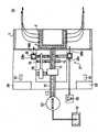
接下来,参考图5,对本发明实施形态3进行说明。实施形态3对实施形态1进行了改变,下面,仅对与实施形态1不同的部分进行说明。图5是表示本发明实施形态3的纳米纤维制造装置的大致结构的侧视图。另外,在本实施形态3中,也可以将容器2更换为容器2A。Next, referring to Fig. 5, Embodiment 3 of the present invention will be described. Embodiment 3 is a modification of
在本实施形态3的纳米纤维制造装置1B中,不使用环状电极3,将用于收集纤维状物质F1的收集器5的鼓28作为与容器2成对的电极来使用。In the
如上所述,收集器5配置在原料液F等通过气流26而偏转的方向上,具有由导体制成的鼓28。鼓28与高压电源4的一个端子(在图示的例子中是负极端子)连接,该高压电源4的另一个端子(在图示的例子中是正极端子)接地。而且,容器2接地,在容器2与鼓28之间产生电场。由此,在容器2和鼓28上分别感应出极性相反的电荷。在图示的例子中,在鼓28上感应出负电荷,在容器2上感应出正电荷。As described above, the collector 5 is arranged in the direction in which the raw material liquid F and the like are deflected by the
在容器2与鼓28之间配置有长条带状的收集体30。收集体30是通过传送机构32与鼓28的周面滑动接触地沿长度方向传送且具有可弯曲性的部件。从原料液F生成的纤维状物质F1堆积在沿长度方向传送的收集体30的表面,作为无纺布被收集。传送机构32具有绕出收集体30的绕出辊34和将收集了纤维状物质F1的收集体30绕回的绕回辊36。An
收集体30最好由薄且具有柔软性的材料构成,以便可以使气流26通过,并且能够容易地将堆积的纤维状物质F1分离,该气流26移送从原料液F生成的纤维状物质F1(纳米纤维)。作为较佳的材料,可以列举由芳族聚酰胺纤维形成的网状膜片。如果在该膜片上涂布特氟隆(注册商标)涂层,则由于进一步提高了纤维状物质F1(纳米纤维)的分离性,因此更佳。The collecting
一般来说,收集体30由绝缘性材料构成,但不限于此,也可以在长条的片状部件中混合碳纳米纤维等导电性材料,使收集体30具有导电性。Generally, the
如上所述,取代环状电极3,将用于收集纤维状物质F1的收集器5的鼓28作为与容器2成对的电极来使用,由此能够避免原料液F或由其形成的纤维状物质F1附着在环状电极3上,不需要进行维护。因此,能够提高生产效率。相反,由于难于将容器2与电极接近配置,因此与实施形态1相比生产性可能略有降低。As mentioned above, instead of the annular electrode 3, the
另外,如图6所示,在本实施形态3中也可以通过电源4向容器2施加高电压,并使鼓28接地。但是,此时也需要用于使容器2和其他部件绝缘的特殊机构。另外,当然可以将实施形态2的结构与本实施形态3的结构组合。In addition, as shown in FIG. 6, in the third embodiment, a high voltage may be applied to the
(实施形态4)(Embodiment 4)
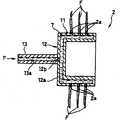
接下来,参考图7,对本发明实施形态4进行说明。实施形态4对实施形态1进行了改变,下面,仅对与实施形态1不同的部分进行说明。图7是表示本发明实施形态4的纳米纤维制造装置的容器的详细结构的剖视图。Next, referring to Fig. 7, Embodiment 4 of the present invention will be described. Embodiment 4 is a modification of
在本实施形态4中使用的容器2B被做成外径在旋转的轴向上直线式变化且圆锥的顶部被切除的外形。容器2B的原料液导入空间7A由形成在距离周壁9的表面一定深度处且径向进深一定的间隙、以及形成在距离圆形壁15的表面一定深度处且轴向进深一定的间隙构成,该圆形壁15相当于圆锥的底面。位于周壁9的内侧的原料液导入空间7A的位置越靠近容器2B的顶端侧(图的右侧),该原料液导入空间7A越接近容器2B的旋转轴。The container 2B used in the fourth embodiment has a shape in which the outer diameter changes linearly in the axial direction of rotation and the top of the cone is cut off. The raw material
并且,原料液供给管13与圆形壁15的中央的外侧表面连接。原料液供给管13的管路13a和容器2A的原料液导入空间7A通过设置在圆形壁15的中央的连通孔15a连通。Furthermore, the raw material
当使用本实施形态4的容器2B时,越靠近气流26的下游侧,从细孔2a放出的原料液F受到的离心力越小。因此,越靠近气流26的下游侧,通过气流26偏转的原料液F等的轨迹越靠近径向内侧。由此,从各细孔2a放出的原料液F等的轨迹在容器2A的径向上分散开来。如果原料液F等的轨迹在容器2A的径向上不分散而集中的话,则会产生由于原料液F所具有的电荷因而从下游侧的细孔2a放出的原料液F的带电受到妨碍、或者原料液F从下游侧的细孔2a的放出受到妨碍等危害。因此,通过使原料液F等的轨迹在容器2B的径向上分散,能够消除这些危害。When the container 2B of the fourth embodiment is used, the centrifugal force received by the raw material liquid F released from the
这里,如图7所示,越靠近气流26的下游侧,容器2B的外径越小,在这种情况下,最好使细孔2a的直径越靠近气流26的下游侧越大,以使从各细孔2a放出的原料液F的流量保持一定。由此,可以使所生成的纤维状物质F1的纤维直径保持一定。Here, as shown in FIG. 7, the closer to the downstream side of the
另外,本实施形态的容器2B不仅能应用于实施形态1,也能应用于实施形态2或3,此时也能获得相同的效果。In addition, the container 2B of this embodiment can be applied not only to
而且,虽然容器2B的外径越靠近气流26的下游侧越直线式变小,但容器2B的外径也可以越靠近气流26的下游侧越直线式变大,此时,也可以使通过气流26偏转的原料液F等的轨迹在容器2A的径向上分散。Moreover, although the outer diameter of the container 2B becomes linearly smaller as it approaches the downstream side of the
实施例Example
下面,对本发明的实施例进行说明。另外,本发明不受以下实施例的限定。Next, examples of the present invention will be described. In addition, this invention is not limited to the following Examples.
在外径60mm、内径57mm的大致圆筒状的容器2的周壁上,以沿容器2的轴向排列6个细孔2a而组成1列、沿容器2的周向排列18列的状态形成总计108个细孔2a。此时,细孔2a的容器2周向的间距为大约20mm。而且,细孔2a的容器2轴向的间距为10mm。On the peripheral wall of a substantially
制作细孔2a的直径为0.20mm(实施例1)、0.30mm(实施例2)和0.50mm(实施例3)这三种的容器2。Three types of
使用分别组装有这三种容器2的图1的纳米纤维制造装置(以下称为实施例装置),使容器2以各种转速旋转20分钟,制造纳米纤维。这里,环状电极3的直径为400mm,电源7的电压为60kV,电源7的负极与环状电极3连接,正极接地。而且,收集体30的传送量为5mm/分。作为高分子材料使用聚乙烯醇(PVA),作为溶剂使用水,将二者混合,将浓度为10质量%的聚乙烯醇的溶液调制成原料液F。Nanofibers were produced by rotating the
另一方面,使用具有图10所示的容器111和供给管112的以往的纳米纤维制造装置(比较例装置),以与上述实施例1~3相同的条件制造纳米纤维。这里,容器111准备细孔113的直径为上述三种(0.20mm(比较例1)、0.30mm(比较例2)和0.50mm(比较例3))的三种容器。On the other hand, nanofibers were produced under the same conditions as in Examples 1 to 3 above using a conventional nanofiber production apparatus (comparative example apparatus) having a container 111 and a supply pipe 112 shown in FIG. 10 . Here, the container 111 prepared three types of containers in which the diameter of the pores 113 was the above three types (0.20 mm (comparative example 1), 0.30 mm (comparative example 2), and 0.50 mm (comparative example 3)).
对于上述实施例1~3和比较例1~3,通过显微镜观察所制造的纳米纤维,对能否制造出未混入高分子物质块的高质量纳米纤维进行研究。其结果如图8所示。在该图中,能够制造出上述高质量纳米纤维的容器2或容器111的转速上限以空心的双头箭头表示。Regarding the above-mentioned Examples 1 to 3 and Comparative Examples 1 to 3, the produced nanofibers were observed under a microscope to examine whether high-quality nanofibers in which polymer substance lumps were not mixed could be produced. The result is shown in Figure 8. In this figure, the upper limit of the rotation speed of the
如图8所示,在实施例1~3中,与细孔2a直径相同的各个比较例1~3相比,即使以较高的转速使容器2旋转,也能够制造出高质量的纳米纤维,这种纳米纤维不会混入未产生静电延伸现象的状态的原料液块。这意味着,既能够从细孔2a放出更多的原料液F又能够制造出高质量的纳米纤维。这样一来,采用本发明,能够更多地生产高质量的纳米纤维。As shown in FIG. 8, in Examples 1 to 3, compared with Comparative Examples 1 to 3 in which the diameter of the
这是因为,在实施例1~3中,能够使从容器2的各细孔2a放出的原料液F的流量保持一定。即,这是因为,在达到更高的转速之前,从各细孔2a放出的原料液F中不会混入电荷密度过少的原料液F。而且,这是因为,在达到更高的转速之前,原料液在从细孔流出时结块而流出的频率降低。This is because, in Examples 1 to 3, the flow rate of the raw material liquid F released from each
而且,本发明的发明人将上述实施例1~3的各容器2应用到实施形态2的纳米纤维制造装置1A中,以与上述实施例1~3相同的条件制造了纳米纤维。而且,对原料液F等附着在环状电极3上的附着量进行了研究。其结果,在上述实施例1~3中,通过20分钟的运行,在环状电极3上发现了少许原料液F等的附着,而与此相对,在使用实施形态2的纳米纤维制造装置1A的实验中,即使运行20分钟后,也几乎不会发现原料液F等对于环状电极3的附着。这样,在本发明的更佳的形态中,能够减少原料液F等对于环状电极3的附着。Furthermore, the inventors of the present invention applied the
另外,在上述实施形态及实施例中,记载了在外周壁上直接形成有多个细孔的容器的情况,但在外周壁上设置喷嘴等突起部、使细孔在该突起部的顶端开口、从该细孔放出原料液的结构也能获得本申请发明的效果。即,通过将处于细孔附近的容器内的原料液的量限制为规定量,以规定压力向容器内部供给原料液,并使上述规定量的原料液受到的离心力保持一定,从而能够稳定地将从细孔流出的原料液控制成固定量。由此,能够更加大量地制造出高质量的纳米纤维,这种纳米纤维不含有未产生静电延伸现象的状态的原料液块。In addition, in the above-mentioned embodiments and examples, it is described that the outer peripheral wall has a plurality of pores directly formed in the case of the container, but a protrusion such as a nozzle is provided on the outer peripheral wall, and the fine hole is opened at the tip of the protrusion. , The structure in which the raw material liquid is released from the pores can also obtain the effect of the invention of the present application. That is, by limiting the amount of the raw material liquid in the container near the pore to a predetermined amount, supplying the raw material liquid into the container at a predetermined pressure, and keeping the centrifugal force received by the predetermined amount of raw material liquid constant, it is possible to stably extract the raw material liquid. The raw material liquid flowing out from the pores is controlled to a fixed amount. As a result, it is possible to produce a larger amount of high-quality nanofibers that do not contain lumps of the raw material solution in a state where the electrostatic stretching phenomenon has not occurred.
产业上的实用性Industrial Applicability
根据本发明的纳米纤维制造装置以及制造方法,当通过静电纺丝法制造纳米纤维时,能够以高生产性制造出高质量的纳米纤维。According to the nanofiber production apparatus and production method of the present invention, when producing nanofibers by electrospinning, high-quality nanofibers can be produced with high productivity.
Claims (2)
Translated fromChineseApplications Claiming Priority (3)
| Application Number | Priority Date | Filing Date | Title |
|---|---|---|---|
| JP2008-257474 | 2008-10-02 | ||
| JP2008257474 | 2008-10-02 | ||
| PCT/JP2009/004480WO2010038362A1 (en) | 2008-10-02 | 2009-09-10 | Method and apparatus for manufacturing nanofiber |
Publications (2)
| Publication Number | Publication Date |
|---|---|
| CN102084043A CN102084043A (en) | 2011-06-01 |
| CN102084043Btrue CN102084043B (en) | 2013-04-10 |
Family
ID=42073148
Family Applications (1)
| Application Number | Title | Priority Date | Filing Date |
|---|---|---|---|
| CN2009801346540AExpired - Fee RelatedCN102084043B (en) | 2008-10-02 | 2009-09-10 | Nanofiber manufacturing device |
Country Status (4)
| Country | Link |
|---|---|
| US (1) | US8524140B2 (en) |
| JP (1) | JPWO2010038362A1 (en) |
| CN (1) | CN102084043B (en) |
| WO (1) | WO2010038362A1 (en) |
Families Citing this family (32)
| Publication number | Priority date | Publication date | Assignee | Title |
|---|---|---|---|---|
| CN104178926B (en) | 2009-01-16 | 2018-02-09 | Zeus工业品公司 | Electrospun is carried out to PTFE using heavy viscous material |
| US20130268062A1 (en) | 2012-04-05 | 2013-10-10 | Zeus Industrial Products, Inc. | Composite prosthetic devices |
| CN102596534B (en) | 2009-08-07 | 2015-04-29 | 宙斯工业产品股份有限公司 | Multilayered composite |
| EP2563956A4 (en) | 2010-10-14 | 2013-09-18 | Zeus Ind Products Inc | Antimicrobial substrate |
| JP5815228B2 (en)* | 2010-12-06 | 2015-11-17 | トップテック・カンパニー・リミテッドTOPTEC Co., Ltd. | Electrospinning apparatus and nanofiber manufacturing apparatus |
| EP2659034B1 (en)* | 2010-12-29 | 2019-02-20 | University of Pittsburgh - Of the Commonwealth System of Higher Education | System and method for mandrel-less electrospinning |
| RU2581871C2 (en) | 2011-01-28 | 2016-04-20 | Мерит Медикал Системз, Инк. | Electrospun ptfe coated stent and method of use |
| US8778240B2 (en) | 2011-02-07 | 2014-07-15 | Fiberio Technology Corporation | Split fiber producing devices and methods for the production of microfibers and nanofibers |
| US11623438B2 (en) | 2012-01-16 | 2023-04-11 | Merit Medical Systems, Inc. | Rotational spun material covered medical appliances and methods of manufacture |
| US9527257B2 (en)* | 2012-08-06 | 2016-12-27 | Clarcor Inc. | Devices and methods for the production of microfibers and nanofibers having one or more additives |
| US10507268B2 (en) | 2012-09-19 | 2019-12-17 | Merit Medical Systems, Inc. | Electrospun material covered medical appliances and methods of manufacture |
| US9198999B2 (en) | 2012-09-21 | 2015-12-01 | Merit Medical Systems, Inc. | Drug-eluting rotational spun coatings and methods of use |
| US20140159263A1 (en)* | 2012-12-04 | 2014-06-12 | Karen Lozano | Portable apparatuses and methods for the production of microfibers and nanofibers |
| WO2014159710A1 (en) | 2013-03-13 | 2014-10-02 | Merit Medical Systems, Inc. | Serially deposited fiber materials and associated devices and methods |
| EP2967929B1 (en) | 2013-03-13 | 2017-11-29 | Merit Medical Systems, Inc. | Methods, systems, and apparatuses for manufacturing rotational spun appliances |
| GB201305463D0 (en)* | 2013-03-25 | 2013-05-08 | Edirisinghe Mohan J | Combining pressure, rotation and an electric field to produce polymetric matter |
| US9988742B2 (en) | 2013-04-12 | 2018-06-05 | Donaldson Company, Inc. | Centrifugal electrospinning process |
| WO2014189780A2 (en)* | 2013-05-20 | 2014-11-27 | Tufts University | Apparatus and method for forming a nanofiber hydrogel composite |
| AU2015233952B2 (en)* | 2014-03-21 | 2017-08-24 | Neworld E & E Pty Ltd. | Multifunctional spinning device |
| WO2015139659A1 (en)* | 2014-03-21 | 2015-09-24 | 馨世工程教育有限公司 | Centrifugal spinning device used for producing composite nano and micron fibers with multiple structures |
| US10240257B2 (en)* | 2014-09-15 | 2019-03-26 | Clarcor Inc. | Systems and methods for controlled laydown of materials in a fiber production system |
| ES2989899T3 (en) | 2015-02-26 | 2024-11-28 | Merit Medical Systems Inc | Medical devices in layers |
| JP6568466B2 (en)* | 2015-04-15 | 2019-08-28 | 花王株式会社 | Electrospinning device |
| CN105624807B (en)* | 2016-04-01 | 2017-12-29 | 厦门大学 | A kind of micropore batch electrostatic spinning apparatus based on Weissenberg effect |
| CN106283220B (en)* | 2016-11-08 | 2018-12-04 | 北京化工大学 | A kind of double electrostatic field electrostatic spinning apparatus of thermal current auxiliary |
| AU2018330936A1 (en) | 2017-09-08 | 2020-03-26 | Board Of Regents Of The University Of Texas System | Mechanoluminescence polymer doped fabrics and methods |
| CN109097849B (en)* | 2018-09-28 | 2021-05-04 | 上海云同新材料科技有限公司 | Nanofiber generating device |
| WO2020172207A1 (en) | 2019-02-20 | 2020-08-27 | Board Of Regents, University Of Texas System | Handheld/portable apparatus for the production of microfibers, submicron fibers and nanofibers |
| CN114086318B (en)* | 2020-08-25 | 2023-02-10 | 华中科技大学 | High-speed cyclone synergistic supergravity melt-blown spinning device and use method thereof |
| US12310987B2 (en) | 2021-02-26 | 2025-05-27 | Merit Medical Systems, Inc. | Fibrous constructs with therapeutic material particles |
| US12320037B2 (en) | 2021-03-02 | 2025-06-03 | Board Of Regents, The University Of Texas System | Handheld/portable apparatus for the production of fine fibers |
| CN114850422B (en)* | 2022-05-16 | 2023-02-28 | 北京化工大学 | Method for preparing metal micro-nano fibers through centrifugal melt electrostatic spinning |
Citations (2)
| Publication number | Priority date | Publication date | Assignee | Title |
|---|---|---|---|---|
| WO2008062784A1 (en)* | 2006-11-24 | 2008-05-29 | Panasonic Corporation | Process and apparatus for producing nanofiber and polymer web |
| JP2008174853A (en)* | 2007-01-16 | 2008-07-31 | Matsushita Electric Ind Co Ltd | Nozzle for polymer fiber generation and polymer fiber generator using the same |
Family Cites Families (6)
| Publication number | Priority date | Publication date | Assignee | Title |
|---|---|---|---|---|
| US5523032A (en)* | 1994-12-23 | 1996-06-04 | Owens-Corning Fiberglas Technology, Inc. | Method for fiberizing mineral material with organic material |
| US7134857B2 (en) | 2004-04-08 | 2006-11-14 | Research Triangle Institute | Electrospinning of fibers using a rotatable spray head |
| JP4448946B2 (en)* | 2004-05-20 | 2010-04-14 | 国立大学法人山梨大学 | A method for producing vinyl-based conductive polymer fibers, and a vinyl-based conductive polymer fiber obtained by the method. |
| WO2008004712A2 (en)* | 2006-07-05 | 2008-01-10 | Panasonic Corporation | Method and apparatus for producing nanofibers and polymeric webs |
| JP4830992B2 (en) | 2006-07-05 | 2011-12-07 | パナソニック株式会社 | Method and apparatus for producing nanofiber and polymer web |
| US9410267B2 (en)* | 2009-05-13 | 2016-08-09 | President And Fellows Of Harvard College | Methods and devices for the fabrication of 3D polymeric fibers |
- 2009
- 2009-09-10CNCN2009801346540Apatent/CN102084043B/ennot_activeExpired - Fee Related
- 2009-09-10USUS13/062,123patent/US8524140B2/ennot_activeExpired - Fee Related
- 2009-09-10JPJP2010531713Apatent/JPWO2010038362A1/enactivePending
- 2009-09-10WOPCT/JP2009/004480patent/WO2010038362A1/enactiveApplication Filing
Patent Citations (2)
| Publication number | Priority date | Publication date | Assignee | Title |
|---|---|---|---|---|
| WO2008062784A1 (en)* | 2006-11-24 | 2008-05-29 | Panasonic Corporation | Process and apparatus for producing nanofiber and polymer web |
| JP2008174853A (en)* | 2007-01-16 | 2008-07-31 | Matsushita Electric Ind Co Ltd | Nozzle for polymer fiber generation and polymer fiber generator using the same |
Also Published As
| Publication number | Publication date |
|---|---|
| US20110156319A1 (en) | 2011-06-30 |
| JPWO2010038362A1 (en) | 2012-02-23 |
| WO2010038362A1 (en) | 2010-04-08 |
| CN102084043A (en) | 2011-06-01 |
| US8524140B2 (en) | 2013-09-03 |
Similar Documents
| Publication | Publication Date | Title |
|---|---|---|
| CN102084043B (en) | Nanofiber manufacturing device | |
| CN101542025B (en) | Method and device for manufacturing nanofibers and polymer networks | |
| JP4877140B2 (en) | Nanofiber manufacturing method and apparatus | |
| CN101981238B (en) | Nanofiber manufacturing device, nanofiber manufacturing method | |
| WO2008062784A1 (en) | Process and apparatus for producing nanofiber and polymer web | |
| JP2009270221A (en) | Apparatus for producing nanofiber | |
| CN102301044B (en) | Nanofiber manufacturing device, nanofiber manufacturing method | |
| JP5782594B1 (en) | Nanofiber forming spray nozzle head and nanofiber manufacturing apparatus comprising nanofiber forming spray nozzle head | |
| JP5225827B2 (en) | Nanofiber manufacturing equipment | |
| JP2009275326A (en) | Apparatus and method for producing nanofiber | |
| WO2016013052A1 (en) | Method for producing nanofibres made from polymer material | |
| JP4866872B2 (en) | Nanofiber manufacturing apparatus and nanofiber manufacturing method | |
| JP5234355B2 (en) | Nanofiber manufacturing apparatus and manufacturing method | |
| JP2016023399A (en) | Ejection nozzle head for forming nanofibers and manufacturing apparatus of nanofibers provided with ejection nozzle head for forming nanofibers | |
| JP5225885B2 (en) | Nanofiber manufacturing apparatus and manufacturing method | |
| JP4853452B2 (en) | Nanofiber manufacturing equipment | |
| JP4954946B2 (en) | Nanofiber manufacturing equipment | |
| JP5185090B2 (en) | Nanofiber manufacturing method and manufacturing apparatus | |
| JP5339362B2 (en) | Nanofiber manufacturing apparatus and manufacturing method | |
| JP5216516B2 (en) | Nanofiber manufacturing apparatus and nanofiber manufacturing method | |
| JP5215207B2 (en) | Nanofiber manufacturing equipment | |
| JP4535085B2 (en) | Nanofiber manufacturing method and apparatus | |
| JP5006862B2 (en) | Nanofiber manufacturing method and manufacturing apparatus | |
| JP4965521B2 (en) | Nanofiber manufacturing equipment | |
| JP2010018898A (en) | Nanofiber manufacturing apparatus and nanofiber manufacturing method |
Legal Events
| Date | Code | Title | Description |
|---|---|---|---|
| C06 | Publication | ||
| PB01 | Publication | ||
| C10 | Entry into substantive examination | ||
| SE01 | Entry into force of request for substantive examination | ||
| C14 | Grant of patent or utility model | ||
| GR01 | Patent grant | ||
| CF01 | Termination of patent right due to non-payment of annual fee | ||
| CF01 | Termination of patent right due to non-payment of annual fee | Granted publication date:20130410 Termination date:20200910 |