CN102083103A - Method and apparatus for determining positioning reference point in interference source positioning system - Google Patents
Method and apparatus for determining positioning reference point in interference source positioning systemDownload PDFInfo
- Publication number
- CN102083103A CN102083103ACN2009102385900ACN200910238590ACN102083103ACN 102083103 ACN102083103 ACN 102083103ACN 2009102385900 ACN2009102385900 ACN 2009102385900ACN 200910238590 ACN200910238590 ACN 200910238590ACN 102083103 ACN102083103 ACN 102083103A
- Authority
- CN
- China
- Prior art keywords
- reference point
- mrow
- determining
- positioning
- msup
- Prior art date
- Legal status (The legal status is an assumption and is not a legal conclusion. Google has not performed a legal analysis and makes no representation as to the accuracy of the status listed.)
- Granted
Links
- 238000000034methodMethods0.000titleclaimsabstractdescription26
- 238000011156evaluationMethods0.000claimsdescription19
- 238000012163sequencing techniqueMethods0.000claims2
- 238000004364calculation methodMethods0.000description8
- 230000005855radiationEffects0.000description6
- 238000005516engineering processMethods0.000description4
- 238000004891communicationMethods0.000description3
- 238000010586diagramMethods0.000description3
- 238000012986modificationMethods0.000description3
- 230000004048modificationEffects0.000description3
- 238000010295mobile communicationMethods0.000description2
- 238000012545processingMethods0.000description2
- 238000013459approachMethods0.000description1
- 238000003491arrayMethods0.000description1
- 230000001174ascending effectEffects0.000description1
- 238000013461designMethods0.000description1
- 230000004807localizationEffects0.000description1
- 238000005457optimizationMethods0.000description1
- 238000011160researchMethods0.000description1
- 230000001360synchronised effectEffects0.000description1
- 238000013024troubleshootingMethods0.000description1
Images


Landscapes
- Position Fixing By Use Of Radio Waves (AREA)
Abstract
Translated fromChineseDescription
Translated fromChinese技术领域technical field
本发明涉及通信技术领域,尤其涉及一种干扰源定位系统中定位参考点的确定方法及装置。The invention relates to the field of communication technology, in particular to a method and device for determining a positioning reference point in an interference source positioning system.
背景技术Background technique
随着无线通信技术的大规模应用,无线环境中的干扰问题日益严重,成为影响公众移动通信网络通信质量的重要因素。目前公众移动通信运营商所采用的办法主要是工程师在干扰源出现的大致位置现场依靠经验逐步逼近,逐点排查干扰源。With the large-scale application of wireless communication technology, the interference problem in the wireless environment is becoming more and more serious, which has become an important factor affecting the communication quality of public mobile communication networks. At present, the method adopted by the public mobile communication operators is mainly that engineers gradually approach the approximate location of the interference source on the spot based on experience, and check the interference source point by point.
随着TD-SCDMA(Time Division-Synchronous Code Division MultipleAccess,时分同步的码分多址)系统的运营,为基于智能天线DOA(DirectionOfArrival,波达方向)估计的辐射源被动定位技术提供了应用基础,可以通过高精度的DOA估计算法来实现干扰源排查的自动化。该类系统的主要思路是通过多个参考点(智能天线阵列)估计出干扰源的来波方向,根据来波方向及参考点位置确定干扰辐射线的数学描述,计算干扰辐射线的交点得出具体干扰源的位置。With the operation of the TD-SCDMA (Time Division-Synchronous Code Division Multiple Access, Time Division Synchronous Code Division Multiple Access) system, it provides an application basis for the passive positioning technology of radiation sources based on smart antenna DOA (DirectionOfArrival) estimation. The automation of interference source troubleshooting can be realized through the high-precision DOA estimation algorithm. The main idea of this type of system is to estimate the incoming wave direction of the interference source through multiple reference points (smart antenna array), determine the mathematical description of the interference radiation line according to the incoming wave direction and the position of the reference point, and calculate the intersection point of the interference radiation line to obtain The location of the specific source of interference.
在基于智能天线DOA估计的辐射源被动定位系统中,为了全面准确的估计待评价干扰源的数量及位置分布,需要多个参考点共同参与定位。但目前所提出的干扰源定位算法主要集中在如何精确的估计干扰源的波达角度上,当网络中参与定位的参考节点数量增加时,一个辐射源可能干扰到多个参考点,定量的研究表明,DOA估计算法的复杂程度呈线将随网络规模呈二次方增长,如果再考虑到随着网络规模的扩大,可能出现的干扰源数量也在线性增长,那么对于传统的DOA估计算法,定位的计算量随着定位区域的扩大呈四次方增长,因此,目前DOA估计算法应用于大规模的网络环境下时,计算的复杂度高,确定干扰源位置的效率低,并且确定干扰源位置的准确度低。In the radiation source passive positioning system based on smart antenna DOA estimation, in order to fully and accurately estimate the number and location distribution of interference sources to be evaluated, multiple reference points are required to participate in the positioning. However, the interference source localization algorithm proposed so far mainly focuses on how to accurately estimate the angle of arrival of the interference source. When the number of reference nodes participating in positioning in the network increases, one radiation source may interfere with multiple reference points. Quantitative research It shows that the complexity of the DOA estimation algorithm will grow quadratically with the network scale, and if it is considered that the number of possible interference sources also increases linearly with the expansion of the network scale, then for the traditional DOA estimation algorithm, The calculation amount of positioning increases with the expansion of the positioning area to the fourth power. Therefore, when the current DOA estimation algorithm is applied to a large-scale network environment, the calculation complexity is high, the efficiency of determining the location of the interference source is low, and the determination of the interference source The location accuracy is low.
发明内容Contents of the invention
有鉴于此,本发明实施例提供一种干扰源定位系统中定位参考点的确定方法及装置,用于提高确定干扰源位置的准确度以及效率。In view of this, embodiments of the present invention provide a method and device for determining a positioning reference point in an interference source location system, which are used to improve the accuracy and efficiency of determining the location of an interference source.
本发明实施例通过如下技术方案实现:Embodiments of the present invention are realized through the following technical solutions:
根据本发明实施例的一个方面,提供了一种干扰源定位系统中定位参考点的确定方法。According to an aspect of an embodiment of the present invention, a method for determining a positioning reference point in an interference source positioning system is provided.
根据本发明实施例提供的干扰源定位系统中定位参考点的确定方法,包括:The method for determining a positioning reference point in an interference source positioning system provided according to an embodiment of the present invention includes:
确定设定数目个参考点集合;并determining a set number of reference point sets; and
确定所述每个参考点集合中各参考点分别对应的第一特征值以及第二特征值,其中,所述第一特征值为在对应参考点上各干扰源的波达角度的均值;所述第二特征值为在对应参考点上用于估计干扰源来波方向的线型天线阵列法线反方向的方位角;Determine the first eigenvalue and the second eigenvalue corresponding to each reference point in each reference point set, wherein the first eigenvalue is the mean value of the angle of arrival of each interference source on the corresponding reference point; The second eigenvalue is the azimuth angle in the opposite direction of the linear antenna array normal for estimating the incoming wave direction of the interference source on the corresponding reference point;
根据所述每个参考点集合中各参考点分别对应的第一特征值以及第二特征值,确定包括用于参与干扰源定位的定位参考点的参考点集合。According to the first eigenvalue and the second eigenvalue respectively corresponding to each reference point in each reference point set, a reference point set including positioning reference points for participating in interference source positioning is determined.
根据本发明实施例的另一个方面,还提供了一种干扰源定位系统中定位参考点的确定装置。According to another aspect of the embodiments of the present invention, a device for determining a positioning reference point in an interference source positioning system is also provided.
根据本发明实施例提供的干扰源定位系统中定位参考点的确定装置,包括:The device for determining a positioning reference point in an interference source positioning system provided according to an embodiment of the present invention includes:
参考点集合确定单元,用于确定设定数目个参考点集合;A reference point set determining unit, configured to determine a set number of reference point sets;
特征值确定单元,用于确定所述参考点集合确定单元确定的每个参考点集合中各参考点分别对应的第一特征值以及第二特征值,其中,所述第一特征值为在对应参考点上各干扰源的波达角度的均值;所述第二特征值为在对应参考点上用于估计干扰源来波方向的线型天线阵列法线反方向的方位角;An eigenvalue determining unit, configured to determine a first eigenvalue and a second eigenvalue respectively corresponding to each reference point in each reference point set determined by the reference point set determining unit, wherein the first eigenvalue is in the corresponding The mean value of the angle of arrival of each interference source on the reference point; The second eigenvalue is the azimuth angle in the opposite direction of the linear antenna array normal for estimating the direction of arrival of the interference source on the corresponding reference point;
定位参考点确定单元,用于根据所述特征值确定单元确定的每个参考点集合中各参考点分别对应的第一特征值以及第二特征值,确定包括用于参与干扰源定位的定位参考点的参考点集合。The positioning reference point determination unit is configured to determine, according to the first eigenvalue and the second eigenvalue respectively corresponding to each reference point in each reference point set determined by the eigenvalue determining unit, the positioning reference used to participate in the positioning of the interference source A collection of reference points for points.
通过本发明实施例提供的上述至少一个技术方案,确定设定数目个参考点集合,并确定每个参考点集合中各参考点分别对应的第一特征值以及第二特征值,其中,第一特征值为在对应参考点上各干扰源的波达角度的均值,第二特征值为在对应参考点上用于估计干扰源来波方向的线型天线阵列法线反方向的方位角;根据每个参考点集合中各参考点分别对应的第一特征值以及第二特征值,确定包括用于参与干扰源定位的定位参考点的参考点集合,根据该技术方案,通过对确定的多个参考点集合进行评价,即根据各参考点集合中包括的参考点对应的波达角度的均值以及用于估计干扰源来波方向的线型天线阵列法线反方向的方位角信息,确定用于参与定位的最佳参考点集合,基于优化后的参考点集合减少了参与定位的定位参考点,减少了计算量,从而提高了确定干扰源位置的效率;并且,通过分析各候选参考点集合对应的特征值,确定最佳参考点集合,并基于确定的最佳参考点集合进行干扰源位置的确定,提高了确定干扰源位置的准确度。Through at least one of the above technical solutions provided by the embodiments of the present invention, a set number of reference point sets are determined, and the first eigenvalue and the second eigenvalue respectively corresponding to each reference point in each reference point set are determined, wherein the first The eigenvalue is the mean value of the angle of arrival of each interference source on the corresponding reference point, and the second eigenvalue is the azimuth angle in the opposite direction of the normal line of the linear antenna array used to estimate the direction of arrival of the interference source on the corresponding reference point; according to The first eigenvalue and the second eigenvalue corresponding to each reference point in each reference point set determine the reference point set including the positioning reference points used to participate in the interference source location. According to the technical solution, by pairing the determined multiple The reference point set is evaluated, that is, according to the mean value of the angle of arrival corresponding to the reference point included in each reference point set and the azimuth angle information in the opposite direction of the normal line of the linear antenna array used to estimate the incoming wave direction of the interference source, determine the The optimal set of reference points involved in positioning, based on the optimized set of reference points, reduces the number of positioning reference points involved in positioning and reduces the amount of calculation, thereby improving the efficiency of determining the location of the interference source; and, by analyzing the corresponding The best reference point set is determined, and the position of the interference source is determined based on the determined best reference point set, which improves the accuracy of determining the position of the interference source.
本发明的其它特征和优点将在随后的说明书中阐述,并且,部分地从说明书中变得显而易见,或者通过实施本发明而了解。本发明的目的和其他优点可通过在所写的说明书、权利要求书、以及附图中所特别指出的结构来实现和获得。Additional features and advantages of the invention will be set forth in the description which follows, and in part will be apparent from the description, or may be learned by practice of the invention. The objectives and other advantages of the invention may be realized and attained by the structure particularly pointed out in the written description and claims hereof as well as the appended drawings.
附图说明Description of drawings
附图用来提供对本发明的进一步理解,并且构成说明书的一部分,与本发明实施例一起用于解释本发明,并不构成对本发明的限制。在附图中:The accompanying drawings are used to provide a further understanding of the present invention, and constitute a part of the description, and are used together with the embodiments of the present invention to explain the present invention, and do not constitute a limitation to the present invention. In the attached picture:
图1为本发明实施例提供的定位参考点的确定方法的流程图一;FIG. 1 is a flow chart 1 of a method for determining a positioning reference point provided by an embodiment of the present invention;
图2为本发明实施例提供的确定包括用于参与干扰源定位的定位参考点的参考点集合的流程图;FIG. 2 is a flow chart of determining a set of reference points including positioning reference points used to participate in interference source positioning provided by an embodiment of the present invention;
图3为本发明实施例提供的定位参考点的确定方法的流程图二;FIG. 3 is a second flowchart of a method for determining a positioning reference point provided by an embodiment of the present invention;
图4为本发明实施例提供的干扰源定位系统中定位参考点的确定装置示意图一;FIG. 4 is a first schematic diagram of an apparatus for determining a positioning reference point in an interference source positioning system provided by an embodiment of the present invention;
图5为本发明实施例提供的干扰源定位系统中定位参考点的确定装置示意图二;FIG. 5 is a second schematic diagram of an apparatus for determining a positioning reference point in an interference source positioning system provided by an embodiment of the present invention;
图6为本发明实施例提供的干扰源定位系统中定位参考点的确定装置示意图三;。FIG. 6 is a third schematic diagram of an apparatus for determining a positioning reference point in the interference source positioning system provided by an embodiment of the present invention;
具体实施方式Detailed ways
为了给出提高确定干扰源位置的准确度以及效率的实现方案,本发明实施例提供了一种干扰源定位系统中定位参考点的确定方法及装置,以下结合说明书附图对本发明的优选实施例进行说明,应当理解,此处所描述的优选实施例仅用于说明和解释本发明,并不用于限定本发明。并且在不冲突的情况下,本申请中的实施例及实施例中的特征可以相互组合。In order to provide an implementation plan for improving the accuracy and efficiency of determining the location of the interference source, the embodiment of the present invention provides a method and device for determining the positioning reference point in the interference source positioning system. The following describes the preferred embodiments of the present invention in conjunction with the accompanying drawings For illustration, it should be understood that the preferred embodiments described here are only used to illustrate and explain the present invention, not to limit the present invention. And in the case of no conflict, the embodiments in the present application and the features in the embodiments can be combined with each other.
根据本发明实施例,首先提供了一种干扰源定位系统中定位参考点的确定方法,该方法从优化参与定位的参考点集合角度出发,给出了确定定位参考点的优化方案。该方法的目标是在所有被辐射源干扰的参考点中,合理的选取一个集合,通过该集合中的参考点可以满足定位的精度要求,并且有效降低干扰源定位算法的总体计算量。According to an embodiment of the present invention, a method for determining a positioning reference point in an interference source positioning system is firstly provided. The method provides an optimization scheme for determining a positioning reference point from the perspective of optimizing a set of reference points participating in positioning. The goal of this method is to reasonably select a set among all the reference points interfered by the radiation source, through which the reference points in the set can meet the positioning accuracy requirements, and effectively reduce the overall calculation amount of the interference source location algorithm.
如图1所示,为本发明实施例提供的干扰源定位系统中定位参考点的确定方法的流程图,主要包括如下步骤:As shown in Figure 1, the flow chart of the method for determining the positioning reference point in the interference source positioning system provided by the embodiment of the present invention mainly includes the following steps:
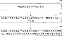
步骤101、确定设定数目个参考点集合。
步骤102、确定每个参考点集合中各参考点分别对应的第一特征值以及第二特征值。
其中,第一特征值为在对应参考点上各干扰源的波达角度的均值;Wherein, the first eigenvalue is the mean value of the angle of arrival of each interference source on the corresponding reference point;
第二特征值为在对应参考点上用于估计干扰源来波方向的线型天线阵列法线反方向的方位角;The second eigenvalue is the azimuth angle in the opposite direction to the normal of the linear antenna array used to estimate the incoming wave direction of the interference source on the corresponding reference point;
步骤103、根据确定的每个参考点集合中各参考点分别对应的第一特征值以及第二特征值,确定包括用于参与干扰源定位的定位参考点的参考点集合。
根据本发明实施例提供的技术方案,步骤101中,确定设定数目个参考点集合,可以有多种方式,例如,根据干扰源定位系统中包括的总的参考点数目,设定参考点集合的数目以及每个参考点集合包括的参考点数目。According to the technical solution provided by the embodiment of the present invention, in
一个较佳的实施例中,确定设定数目个参考点集合,可以通过如下过程:In a preferred embodiment, the set number of reference point sets can be determined through the following process:
根据干扰源定位系统中所有参考点的数目N以及设定的参与干扰源定位的定位参考点的数目n,确定参考点集合的数目M;其中,
从N个参考点中分别为M个参考点集合选择n个参考点;其中,M个参考点集合中的任两个参考点集合至少有一个参考点不同。Select n reference points from the N reference points for the M reference point sets respectively; wherein, any two reference point sets in the M reference point sets have at least one different reference point.
更为具体地,从N个参考点中分别为M个参考点集合选择n个参考点,具体包括如下过程:More specifically, selecting n reference points from the N reference points for M reference point sets respectively, specifically includes the following process:
根据排列组合原理,从N个参考点中确定M个参考点集合分别包括的n个参考点。According to the principle of permutation and combination, the n reference points respectively included in the M reference point sets are determined from the N reference points.
根据本发明实施例提供的技术方案,步骤103中,根据确定的每个参考点集合中各参考点分别对应的第一特征值以及第二特征值,确定包括用于参与干扰源定位的定位参考点的参考点集合的过程,如图2所示,具体包括如下步骤:According to the technical solution provided by the embodiment of the present invention, in
步骤201、对每个参考点集合中各参考点分别对应的第一特征值按从小到大排序。
步骤202、根据第一特征值的排序结果,对每个参考点集合中各参考点的第二特征值排序。
该步骤具体包括:按照第一特征值从小到大的顺序对所述每个参考点集合中各参考点进行排序,分别对排序后的各参考点按照排序顺序依次提取对应的第一特征值组成第一特征值序列,并分别对排序后的各参考点按照排序顺序依次提取对应的第二特征值组成第二特征值序列。This step specifically includes: sorting the reference points in each reference point set according to the order of the first eigenvalues from small to large, respectively extracting the corresponding first eigenvalues from the sorted reference points according to the sorting order. The first eigenvalue sequence, and sequentially extracting the corresponding second eigenvalues from the sorted reference points according to the sort order to form the second eigenvalue sequence.
步骤203、根据排序得到的第一特征值序列以及第二特征值序列,按照设定公式确定每个参考点集合对应的评价函数值。
该步骤中,确定每个参考点集合对应的评价函数值的公式如下:In this step, the formula for determining the evaluation function value corresponding to each reference point set is as follows:
其中:in:
Xi′为所述第一特征值序列中排在第i位的第一特征值;Xi' is the first eigenvalue ranked i in the first eigenvalue sequence;
Yi′为所述第二特征值序列中排在第i位的第二特征值;Yi' is the second eigenvalue ranked i in the second eigenvalue sequence;
步骤204、在确定的每个参考点集合对应的评价函数值中,选择具有最小评价函数值的参考点集合为包括用于参与干扰源定位的定位参考点的参考点集合。Step 204: Among the determined evaluation function values corresponding to each reference point set, select the reference point set with the smallest evaluation function value as the reference point set including positioning reference points for participating in interference source positioning.
更为具体地,上述步骤202中,根据第一特征值的排序结果,对每个参考点集合中各参考点的第二特征值排序,具体包括:More specifically, in the
确定与排序后各第一特征值分别对应的参考点;Determining reference points respectively corresponding to each first eigenvalue after sorting;
根据第一特征值的排序结果,对与各第一特征值分别对应的参考点的第二特征值排序。According to the sorting result of the first eigenvalues, the second eigenvalues of the reference points respectively corresponding to the first eigenvalues are sorted.
以下为根据本发明上述实施例提供的技术方案的一个较佳的实施方式,首先对本发明实施例涉及的参数进行如下说明:The following is a preferred implementation of the technical solution provided according to the above-mentioned embodiments of the present invention. First, the parameters involved in the embodiments of the present invention are described as follows:
N:系统中包括的参考点数目,本发明实施例中,参考点即为参与定位的智能天线阵列,其中,N个参考点分别表示为参考点1、参考点2、......参考点N;N: the number of reference points included in the system. In the embodiment of the present invention, the reference points are the smart antenna arrays involved in positioning, where the N reference points are represented as reference point 1, reference point 2, ...... reference point N;
Xi:在参考点i上各个干扰源的波达角度的均值(以下描述中称为波达角度均值),其中,i=1、2......、N;Xi: the mean value of the angle of arrival of each interference source on the reference point i (referred to as the mean value of the angle of arrival in the following description), wherein, i=1, 2..., N;
Yi:在参考点i上用于估计干扰源来波方向的线型天线阵列法线反方向的方位角(以下描述中称为方位角),其中,i=1、2......、N。Yi: the azimuth angle (referred to as the azimuth angle in the following description) in the opposite direction of the linear antenna array normal for estimating the incoming wave direction of the interference source at the reference point i, where i=1, 2... , N.
以上例为基础,如图3所示,定位参考点的确定方法,包括如下步骤:Based on the above example, as shown in Figure 3, the method for determining the positioning reference point includes the following steps:
步骤301、确定在N个参考点中参与定位的参考点集合中元素的个数n,n<N。
该步骤中,n可以根据系统对定位精度的要求并参考计算量的复杂度进行调整,例如,在参考点集合包括不同数目的参考点的情况下,统计确定的干扰源的位置与实际干扰源的位置之间的差值,并取具有最小位置差值的参考点集合中包括的参考点数目作为n的值。一般情况下,n可以取3,在系统对定位精度有更高的要求时,n可以取更大的值,但n越大,计算的复杂度越大,因此,需要考虑精度与计算复杂度之间的平衡。In this step, n can be adjusted according to the requirements of the system for positioning accuracy and the complexity of the calculation amount. The difference between the positions, and take the number of reference points included in the set of reference points with the smallest position difference as the value of n. In general, n can be 3. When the system has higher requirements for positioning accuracy, n can take a larger value, but the larger n is, the greater the computational complexity is. Therefore, it is necessary to consider the accuracy and computational complexity. balance between.
步骤302、分别针对系统中包括的每个参考点计算其对应的波达角度均值X以及方位角Y。
该步骤中,确定参考点i的波达角度均值Xi,即首先针对该参考点i,确定来自各个干扰源的波达角度,并计算各个波达角度的平均值得到Xi;In this step, the mean value of the angle of arrival Xi of the reference point i is determined, that is, firstly, for the reference point i, the angle of arrival from each interference source is determined, and the average value of each angle of arrival is calculated to obtain Xi;
确定参考点i的方位角Yi,即首先确定该参考点的法线方向,并做取反处理(旋转180度),得到该参考点i对应的方位角Yi。Determine the azimuth Yi of the reference point i, that is, first determine the normal direction of the reference point, and perform inverse processing (rotate 180 degrees), to obtain the azimuth Yi corresponding to the reference point i.
步骤303、按照确定的n,根据排列组合原理生成M个参考点集合A1,A2......AM。
其中,每个参考点集合包括n个参考点,并且M的数量由n在N中的所有组合遍历得到,即
上述步骤302和步骤303的执行顺序可以调换。The execution order of the above-mentioned
对于步骤303产生的每个集合Ai(i=1、2......M),分别执行步骤304~步骤306:For each set Ai (i=1, 2...M) that step 303 produces, execute
步骤304、对集合Ai内各个参考点对应的波达角度均值X,按从小到大排列,生成序列{X1’,X2’......Xn’}。Step 304: Arrange the mean values of the angles of arrival X corresponding to each reference point in the set Ai from small to large to generate a sequence {X1', X2'...Xn'}.
步骤305、根据X1’,X2’......Xn’的排序,重新排列对应的方位角Y,得到序列{Y1’,Y2’......Yn’}。
根据本发明实施例,每个参考点都对应一个波达角度均值X以及一个方位角Y,也即参考点、波达角度均值X以及方位角Y之间存在对应关系,步骤305基于该对应关系以及X1’,X2’......Xn’的排序,得到与波达角度均值序列{X1’,X2’......Xn’}对应的方位角Y序列{Y1’,Y2’......Yn’}。According to the embodiment of the present invention, each reference point corresponds to a mean value of the angle of arrival X and an azimuth angle Y, that is, there is a corresponding relationship between the reference point, the mean value of the angle of arrival X, and the azimuth angle Y, and step 305 is based on the corresponding relationship And the sorting of X1', X2'...Xn', the azimuth Y sequence {Y1', Y2 corresponding to the mean value sequence {X1', X2'...Xn'} of the wave arrival angle is obtained '...Yn'}.
步骤306、根据集合Ai内重排序后的波达角度均值X以及方位角Y,计算集合Ai对应的评价函数F:
该公式的物理含义如下:The physical meaning of this formula is as follows:
第一部分(即加号前面的部分)表示两个相邻参考点所估计的波达角度均值之差;The first part (i.e. the part before the plus sign) represents the difference between the mean values of the angles of arrival estimated by two adjacent reference points;
第二部分(即加号后面的部分)表示波达来向和参考点法线方向的差值。The second part (that is, the part after the plus sign) represents the difference between the direction of arrival and the normal direction of the reference point.
步骤307、根据步骤304~步骤306计算得到的各个集合对应的评价函数F,选择F值最小的集合Amin,以集合Amin所包含的参考点作为参与定位的参考点。
该步骤中,根据设计目的,要求两个相邻参考点所估计的波达角度均值之差尽量接近2π(通过上述F计算公式中的第一部分表征),以保证所选参考点均匀的分布在定位干扰源的四周;并且,要求波达来向和参考点法线方向的差值最小(通过上述F计算公式中的第二部分表征),以保证干扰源入射参考点时与法线方向最接近,从而将具有最小F值的集合所包含的参考点作为参与定位的参考点。In this step, according to the design purpose, the difference between the mean values of the angles of arrival estimated by two adjacent reference points is required to be as close to 2π as possible (characterized by the first part of the above F calculation formula), so as to ensure that the selected reference points are evenly distributed in Locate the surroundings of the interference source; and, the difference between the direction of arrival and the normal direction of the reference point is required to be the smallest (characterized by the second part of the above F calculation formula), so as to ensure that the interference source is closest to the normal direction when it is incident on the reference point. close, so that the reference point included in the set with the smallest F value is used as the reference point involved in positioning.
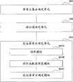
与上述流程对应,本发明实施例还提供了一种干扰源定位系统中定位参考点的确定装置,如图4所示,该装置包括:Corresponding to the above process, an embodiment of the present invention also provides a device for determining a positioning reference point in an interference source positioning system, as shown in FIG. 4 , the device includes:
参考点集合确定单元401、特征值确定单元402以及定位参考点确定单元403;A reference point set
其中:in:
参考点集合确定单元401,用于确定设定数目个参考点集合;A reference point set determining
特征值确定单元402,用于确定参考点集合确定单元401确定的每个参考点集合中各参考点分别对应的第一特征值以及第二特征值,其中,所述第一特征值为在对应参考点上各干扰源的波达角度的均值;所述第二特征值为在对应参考点上用于估计干扰源来波方向的线型天线阵列法线反方向的方位角;The feature
定位参考点确定单元403,用于根据特征值确定单元402确定的每个参考点集合中各参考点分别对应的第一特征值以及第二特征值,确定包括用于参与干扰源定位的定位参考点的参考点集合。The positioning reference
如图5所示,本发明又一实施例中,图4所示的参考点集合确定单元401,还可以进一步包括:As shown in FIG. 5, in another embodiment of the present invention, the reference point set determining
参考点集合数目确定模块401A,用于根据干扰源定位系统中所有参考点的数目N以及设定的参与干扰源定位的定位参考点的数目n,确定参考点集合的数目M;其中,
参考点确定模块401B,用于从所述N个参考点中分别为所述M个参考点集合选择n个参考点;所述M个参考点集合中的任两个参考点集合至少有一个参考点不同。The reference
更为具体地,上述参考点确定模块401B,具体用于:More specifically, the above-mentioned reference
根据排列组合原理从所述N个参考点中确定所述M个参考点集合分别包括的n个参考点。The n reference points respectively included in the M reference point sets are determined from the N reference points according to the permutation and combination principle.
如图6所示,本发明又一实施例中,图4所示的定位参考点确定单元403,还可以进一步包括:As shown in FIG. 6, in yet another embodiment of the present invention, the positioning reference
排序模块403A,用于按照第一特征值从小到大的顺序对所述每个参考点集合中各参考点进行排序,分别对排序后的各参考点按照排序顺序依次提取对应的第一特征值组成第一特征值序列,并分别对排序后的各参考点按照排序顺序依次提取对应的第二特征值组成第二特征值序列;The
评价函数值确定模块403B,用于根据排序模块403A排序得到的第一特征值序列以及第二特征值序列,按照如下公式确定所述每个参考点集合对应的评价函数值:The evaluation function
其中:in:
Xi′为所述第一特征值序列中排在第i位的第一特征值;Yi′为所述第二特征值序列中排在第i位的第二特征值;Xi' is the first eigenvalue ranked i in the first eigenvalue sequence; Yi' is the second eigenvalue ranked i in the second eigenvalue sequence;
定位参考点确定模块403C,用于从评价函数值确定模块403B确定的所述每个参考点集合对应的评价函数值中,选择具有最小评价函数值的参考点集合为包括用于参与干扰源定位的定位参考点的参考点集合。The positioning reference
应当理解,该实施例提供的定位参考点的确定装置所实现的功能与上述实施例提供的定位参考点的确定方法流程一一对应,对于该装置各个功能单元所实现的更为详细的处理流程,在上述方法实施例中已做详细描述,此处不再详细描述。It should be understood that the functions implemented by the device for determining the positioning reference point provided in this embodiment correspond one-to-one to the flow of the method for determining the positioning reference point provided in the above-mentioned embodiment. For the more detailed processing flow implemented by each functional unit of the device , has been described in detail in the foregoing method embodiments, and will not be described in detail here.
通过本发明实施例提供的上述至少一个技术方案,确定设定数目个参考点集合,并确定每个参考点集合中各参考点分别对应的第一特征值以及第二特征值,其中,第一特征值为在对应参考点上各干扰源的波达角度的均值,第二特征值为在对应参考点上用于估计干扰源来波方向的线型天线阵列法线反方向的方位角;根据每个参考点集合中各参考点分别对应的第一特征值以及第二特征值,确定包括用于参与干扰源定位的定位参考点的参考点集合,根据该技术方案,通过对确定的多个参考点集合进行评价,即根据各参考点集合中包括的参考点对应的波达角度的均值以及用于估计干扰源来波方向的线型天线阵列法线反方向的方位角信息,确定用于参与定位的最佳参考点集合,基于优化后的参考点集合减少了参与定位的定位参考点,减少了计算量,从而提高了确定干扰源位置的效率;并且,通过分析各候选参考点集合对应的特征值,确定最佳参考点集合,并基于确定的最佳参考点集合进行干扰源位置的确定,提高了确定干扰源位置的准确度。Through at least one of the above technical solutions provided by the embodiments of the present invention, a set number of reference point sets are determined, and the first eigenvalue and the second eigenvalue respectively corresponding to each reference point in each reference point set are determined, wherein the first The eigenvalue is the mean value of the angle of arrival of each interference source on the corresponding reference point, and the second eigenvalue is the azimuth angle in the opposite direction of the normal line of the linear antenna array used to estimate the direction of arrival of the interference source on the corresponding reference point; according to The first eigenvalue and the second eigenvalue corresponding to each reference point in each reference point set determine the reference point set including the positioning reference points used to participate in the interference source location. According to the technical solution, by pairing the determined multiple The reference point set is evaluated, that is, according to the mean value of the angle of arrival corresponding to the reference point included in each reference point set and the azimuth angle information in the opposite direction of the normal line of the linear antenna array used to estimate the incoming wave direction of the interference source, determine the The optimal set of reference points involved in positioning, based on the optimized set of reference points, reduces the number of positioning reference points involved in positioning and reduces the amount of calculation, thereby improving the efficiency of determining the location of the interference source; and, by analyzing the corresponding The best reference point set is determined, and the position of the interference source is determined based on the determined best reference point set, which improves the accuracy of determining the position of the interference source.
显然,本领域的技术人员可以对本发明进行各种改动和变型而不脱离本发明的精神和范围。这样,倘若本发明的这些修改和变型属于本发明权利要求及其等同技术的范围之内,则本发明也意图包含这些改动和变型在内。Obviously, those skilled in the art can make various changes and modifications to the present invention without departing from the spirit and scope of the present invention. Thus, if these modifications and variations of the present invention fall within the scope of the claims of the present invention and equivalent technologies thereof, the present invention also intends to include these modifications and variations.
Claims (8)
Priority Applications (1)
| Application Number | Priority Date | Filing Date | Title |
|---|---|---|---|
| CN 200910238590CN102083103B (en) | 2009-11-27 | 2009-11-27 | Method and apparatus for determining positioning reference point in interference source positioning system |
Applications Claiming Priority (1)
| Application Number | Priority Date | Filing Date | Title |
|---|---|---|---|
| CN 200910238590CN102083103B (en) | 2009-11-27 | 2009-11-27 | Method and apparatus for determining positioning reference point in interference source positioning system |
Publications (2)
| Publication Number | Publication Date |
|---|---|
| CN102083103Atrue CN102083103A (en) | 2011-06-01 |
| CN102083103B CN102083103B (en) | 2012-12-05 |
Family
ID=44088814
Family Applications (1)
| Application Number | Title | Priority Date | Filing Date |
|---|---|---|---|
| CN 200910238590ActiveCN102083103B (en) | 2009-11-27 | 2009-11-27 | Method and apparatus for determining positioning reference point in interference source positioning system |
Country Status (1)
| Country | Link |
|---|---|
| CN (1) | CN102083103B (en) |
Cited By (8)
| Publication number | Priority date | Publication date | Assignee | Title |
|---|---|---|---|---|
| CN102892137A (en)* | 2011-07-21 | 2013-01-23 | 中国移动通信集团北京有限公司 | Method and apparatus for locating interference source |
| CN104459713A (en)* | 2014-12-10 | 2015-03-25 | 西安建筑科技大学 | Method used for estimating direction of arrival of deception jamming through satellite navigation receiver |
| CN105530703A (en)* | 2016-01-28 | 2016-04-27 | 中国铁建电气化局集团北方工程有限公司 | A GSM-R Interference Source Location Method Based on Direction of Arrival Estimation |
| CN106255200A (en)* | 2016-07-29 | 2016-12-21 | 昆明理工大学 | A kind of air interference source location method based on gridding spectrum monitoring result |
| CN106332109A (en)* | 2015-07-10 | 2017-01-11 | 中国移动通信集团公司 | An interference source location system and method |
| CN106842151A (en)* | 2015-12-03 | 2017-06-13 | 中国航空工业集团公司雷华电子技术研究所 | Based on the Passive Positioning method of testing that guinea pig system interference source azimuth angle is constant |
| CN107037422A (en)* | 2017-05-11 | 2017-08-11 | 西北大学 | A kind of passive type localization method towards multiple application |
| CN110677865A (en)* | 2019-09-25 | 2020-01-10 | 北京邮电大学 | Method for positioning external interference source of mobile communication network |
Citations (2)
| Publication number | Priority date | Publication date | Assignee | Title |
|---|---|---|---|---|
| CN1798414A (en)* | 2004-12-23 | 2006-07-05 | 华为技术有限公司 | Method for locating interference source in up going route |
| US20090167598A1 (en)* | 2005-12-09 | 2009-07-02 | Nec Corporation | Positioning method, positioning device, and program |
- 2009
- 2009-11-27CNCN 200910238590patent/CN102083103B/enactiveActive
Patent Citations (2)
| Publication number | Priority date | Publication date | Assignee | Title |
|---|---|---|---|---|
| CN1798414A (en)* | 2004-12-23 | 2006-07-05 | 华为技术有限公司 | Method for locating interference source in up going route |
| US20090167598A1 (en)* | 2005-12-09 | 2009-07-02 | Nec Corporation | Positioning method, positioning device, and program |
Cited By (13)
| Publication number | Priority date | Publication date | Assignee | Title |
|---|---|---|---|---|
| CN102892137B (en)* | 2011-07-21 | 2015-02-04 | 中国移动通信集团北京有限公司 | Method and apparatus for locating interference source |
| CN102892137A (en)* | 2011-07-21 | 2013-01-23 | 中国移动通信集团北京有限公司 | Method and apparatus for locating interference source |
| CN104459713A (en)* | 2014-12-10 | 2015-03-25 | 西安建筑科技大学 | Method used for estimating direction of arrival of deception jamming through satellite navigation receiver |
| CN106332109B (en)* | 2015-07-10 | 2019-10-18 | 中国移动通信集团公司 | A kind of interference source positioning system and method |
| CN106332109A (en)* | 2015-07-10 | 2017-01-11 | 中国移动通信集团公司 | An interference source location system and method |
| CN106842151B (en)* | 2015-12-03 | 2019-11-26 | 中国航空工业集团公司雷华电子技术研究所 | Based on the Passive Positioning test method that guinea pig system interference source azimuth angle is constant |
| CN106842151A (en)* | 2015-12-03 | 2017-06-13 | 中国航空工业集团公司雷华电子技术研究所 | Based on the Passive Positioning method of testing that guinea pig system interference source azimuth angle is constant |
| CN105530703A (en)* | 2016-01-28 | 2016-04-27 | 中国铁建电气化局集团北方工程有限公司 | A GSM-R Interference Source Location Method Based on Direction of Arrival Estimation |
| CN105530703B (en)* | 2016-01-28 | 2018-10-26 | 中国铁建电气化局集团北方工程有限公司 | A kind of GSM-R interference source localization methods based on Mutual coupling value |
| CN106255200B (en)* | 2016-07-29 | 2019-07-05 | 昆明理工大学 | A kind of air interference source localization method based on gridding spectrum monitoring result |
| CN106255200A (en)* | 2016-07-29 | 2016-12-21 | 昆明理工大学 | A kind of air interference source location method based on gridding spectrum monitoring result |
| CN107037422A (en)* | 2017-05-11 | 2017-08-11 | 西北大学 | A kind of passive type localization method towards multiple application |
| CN110677865A (en)* | 2019-09-25 | 2020-01-10 | 北京邮电大学 | Method for positioning external interference source of mobile communication network |
Also Published As
| Publication number | Publication date |
|---|---|
| CN102083103B (en) | 2012-12-05 |
Similar Documents
| Publication | Publication Date | Title |
|---|---|---|
| CN102083103B (en) | Method and apparatus for determining positioning reference point in interference source positioning system | |
| Zheng et al. | Exploiting fingerprint correlation for fingerprint-based indoor localization: A deep learning-based approach | |
| Zhao et al. | Collaborative signal and information processing: an information-directed approach | |
| CN109068267B (en) | Indoor positioning method based on LoRa SX1280 | |
| Lian et al. | Optimal sensor placement for large structures using the nearest neighbour index and a hybrid swarm intelligence algorithm | |
| Xiang et al. | Robust sub-meter level indoor localization with a single WiFi access point—Regression versus classification | |
| CN108540929B (en) | Indoor fingerprint positioning method based on RSSI signal strength sequencing | |
| CN107493578A (en) | Wireless network deployment method and device | |
| CN106612511B (en) | Wireless network throughput evaluation method and device based on support vector machine | |
| CN104684081A (en) | Node localization algorithm for selecting anchor nodes based on distance clustering in wireless sensor networks | |
| CN104038901A (en) | Indoor positioning method for reducing fingerprint data acquisition workload | |
| CN115987816A (en) | Network flow prediction method and device, electronic equipment and readable storage medium | |
| CN105334497A (en) | Three-dimensional positioning method and device | |
| Fang et al. | Multi‐channel fingerprint localisation algorithm for wireless sensor network in multipath environment | |
| Zhang et al. | Indoor fingerprint localization algorithm based on WKNN and LightGBM-GA | |
| CN101772013A (en) | Voting mechanism based WSN anti-attack node positioning method | |
| KR20120132908A (en) | Method for determining location using the access point and apparatus thereof | |
| CN113573406B (en) | Fingerprint information positioning method based on wireless signal strength | |
| CN109803234A (en) | Unsupervised fusion and positioning method based on the constraint of weight different degree | |
| Lyu et al. | Deep Learning‐Based Bluetooth Low‐Energy 5.1 Multianchor Indoor Positioning with Attentional Data Filtering | |
| Wang et al. | 5g1m: Indoor fingerprint positioning using a single 5g module | |
| CN104965190B (en) | Axial direction decoupling indoor orientation method based on location fingerprint | |
| CN106646347A (en) | Ecological niche differential evolution-based multi-signal classification spectral peak search method | |
| Kakisim et al. | Multi-channel convolutional neural network with attention mechanism using dual-band WiFi signals for indoor positioning systems in smart buildings | |
| Shen et al. | Enhancing Wi-Fi RSS-based indoor positioning under dynamic AP availability: Leveraging virtual feature maps and contrastive learning |
Legal Events
| Date | Code | Title | Description |
|---|---|---|---|
| C06 | Publication | ||
| PB01 | Publication | ||
| C10 | Entry into substantive examination | ||
| SE01 | Entry into force of request for substantive examination | ||
| C14 | Grant of patent or utility model | ||
| GR01 | Patent grant |