CN102074446A - Magnetron with adjustable compound trace - Google Patents
Magnetron with adjustable compound traceDownload PDFInfo
- Publication number
- CN102074446A CN102074446ACN 201010588625CN201010588625ACN102074446ACN 102074446 ACN102074446 ACN 102074446ACN 201010588625CN201010588625CN 201010588625CN 201010588625 ACN201010588625 ACN 201010588625ACN 102074446 ACN102074446 ACN 102074446A
- Authority
- CN
- China
- Prior art keywords
- magnetron
- assembly
- drive assembly
- sputtering target
- rotary drive
- Prior art date
- Legal status (The legal status is an assumption and is not a legal conclusion. Google has not performed a legal analysis and makes no representation as to the accuracy of the status listed.)
- Granted
Links
Images


Landscapes
- Physical Vapour Deposition (AREA)
Abstract
Translated fromChinese
Description
Translated fromChinese技术领域technical field
本发明涉及一种用于控制磁电管运动的机械装置,特别涉及一种复合轨迹可调式磁电管。The invention relates to a mechanical device for controlling the motion of a magnetron, in particular to a compound track adjustable magnetron.
背景技术Background technique
溅射是自20世纪初开始逐渐得到发展与应用的一种PVD技术。溅射作为一种镀膜技术,由于它比蒸发镀膜方法的台阶覆盖性能好,比电子束缚蒸发方法的辐射缺陷少,而在集成电路电性互联等制造工艺中常被采用。Sputtering is a PVD technology that has been gradually developed and applied since the beginning of the 20th century. As a coating technology, sputtering is often used in manufacturing processes such as integrated circuit electrical interconnections because it has better step coverage than the evaporation coating method and fewer radiation defects than the electron confinement evaporation method.
溅射过程中先用真空泵把溅射腔室抽成高真空,然后充入如氩气等惰性气体,并且在溅射靶上施加几百伏的负偏置电压,使惰性气体与电子碰撞后电离导致辉光放电形成等离子体,正离子在电场加速作用下撞击溅射靶表面,入射正离子与溅射靶中原子发生连锁碰撞,使溅射靶表面的原子获得动能脱离晶格束缚,飞溅沉积到被溅射材料的表面形成薄膜。在溅射时,通常利用磁电管在溅射靶表面形成一个磁场,以加速电子运动,增加它们与惰性气体原子碰撞产生正离子的几率,这种工艺被称为磁控溅射。During the sputtering process, the sputtering chamber is first evacuated into a high vacuum by a vacuum pump, and then filled with an inert gas such as argon, and a negative bias voltage of several hundred volts is applied to the sputtering target, so that the inert gas collides with electrons Ionization causes glow discharge to form plasma, and the positive ions hit the surface of the sputtering target under the acceleration of the electric field, and the incident positive ions collide with the atoms in the sputtering target, so that the atoms on the surface of the sputtering target gain kinetic energy and break away from the lattice constraints, and the sputtering Deposits onto the surface of the sputtered material to form a thin film. During sputtering, a magnetron is usually used to form a magnetic field on the surface of the sputtering target to accelerate the movement of electrons and increase the probability of them colliding with inert gas atoms to generate positive ions. This process is called magnetron sputtering.
一个理想的磁控溅射系统,形成的平行于溅射靶表面的磁场分量应均匀地覆盖在溅射靶表面,因为只有水平分量才能提高溅射效率。由于结构尺寸、重量、制造工艺与成本、功耗、维护等因素的限制,实际上的磁控溅射系统中溅射靶表面磁场的均匀性和覆盖率很难达到上述理想状态。从溅射靶材利用率指标就可以反映出溅射靶表面磁场与上述理想状态的差距,目前常规磁控溅射系统的溅射靶材利用率是30%左右,某些优化的磁控溅射系统的溅射靶材利用率可能达到60-70%。需要指出的是,提高平行于溅射靶表面的磁场分量均匀性和覆盖率,不仅可以提高溅射靶材利用率,而且对提高沉积在被溅射材料表面上薄膜厚度的均匀性、台阶覆盖率等镀膜质量具有重要作用。In an ideal magnetron sputtering system, the magnetic field component formed parallel to the surface of the sputtering target should evenly cover the surface of the sputtering target, because only the horizontal component can improve the sputtering efficiency. Due to the limitations of structural size, weight, manufacturing process and cost, power consumption, maintenance and other factors, it is difficult for the uniformity and coverage of the magnetic field on the surface of the sputtering target in the actual magnetron sputtering system to reach the above ideal state. The gap between the sputtering target surface magnetic field and the above ideal state can be reflected from the sputtering target utilization index. At present, the sputtering target utilization rate of the conventional magnetron sputtering system is about 30%. Some optimized magnetron sputtering systems The sputtering target utilization of the sputtering system may reach 60-70%. It should be pointed out that improving the uniformity and coverage of the magnetic field component parallel to the surface of the sputtering target can not only improve the utilization rate of the sputtering target, but also improve the uniformity and step coverage of the film deposited on the surface of the sputtered material. Coating quality such as rate plays an important role.
通常采用优化磁电管的结构及控制磁场随时间变化的规律来提高平行于溅射靶表面磁场分量的均匀性和覆盖率。前者通过改变磁电管的空间几何结构及排列,提高溅射靶表面磁场覆盖率和均匀性;后者通过在溅射靶周围布置电磁线圈,或者采用机械装置使磁电管在溅射靶背后进行旋转等运动,达到提高溅射靶表面磁场覆盖率和均匀性的目的。The uniformity and coverage of the magnetic field component parallel to the surface of the sputtering target are usually improved by optimizing the structure of the magnetron and controlling the law of the magnetic field changing with time. The former improves the coverage and uniformity of the magnetic field on the surface of the sputtering target by changing the spatial geometry and arrangement of the magnetron; the latter arranges electromagnetic coils around the sputtering target, or uses a mechanical device to make the magnetron behind the sputtering target Perform rotation and other movements to achieve the purpose of improving the coverage and uniformity of the magnetic field on the surface of the sputtering target.
采用机械装置使磁电管在溅射靶背后进行旋转等运动,来提高溅射靶表面磁场覆盖率和均匀性的相关专利较多。There are many related patents that use mechanical devices to make the magnetron rotate behind the sputtering target to improve the coverage and uniformity of the magnetic field on the surface of the sputtering target.
例如浙江大学王德苗和任高潮的中国专利ZL87106947提出了一种“分离磁体式平面磁控溅射源”。王德苗和任高潮设计了旋转式磁电管,其磁电管有三种结构形式:1)由V形外磁铁(N极)、扇形偏心内磁铁(S极)和圆心位于转动中心的O形外磁环(N极)组成;2)由辐射状外磁铁(N极)、与外磁铁个数相对应的扇形偏心内磁铁(S极)和圆心位于转动中心的O形外磁环(N极)组成,例如辐射状外磁铁为X形时,有4个扇形偏心内磁铁;3)由两个ω外磁铁(N极)、一个圆心位于转动中心且形状与外磁铁形状相匹配内磁铁(S极)、一个圆心位于转动中心的O形外磁环(N极)组成。王德苗和任高潮设计的旋转式磁电管最主要的特点是磁电管的N极是分离式的,由外磁铁和外磁环两部分构成,外磁环固定不动,外磁铁和内磁铁做旋转运动。For example, the Chinese patent ZL87106947 of Wang Demiao and Ren Gaochao of Zhejiang University proposed a "separated magnet type planar magnetron sputtering source". Wang Demiao and Ren Gaochao designed a rotary magnetron, which has three structural forms: 1) It consists of a V-shaped outer magnet (N pole), a fan-shaped eccentric inner magnet (S pole), and an O magnetron whose center is located at the center of rotation. 2) It consists of radial outer magnets (N poles), fan-shaped eccentric inner magnets (S poles) corresponding to the number of outer magnets, and O-shaped outer magnetic rings ( N pole), for example, when the radial outer magnet is X-shaped, there are four fan-shaped eccentric inner magnets; 3) It consists of two ω outer magnets (N poles), one center of which is located at the center of rotation and the shape matches the shape of the outer magnet. It consists of a magnet (S pole) and an O-shaped outer magnetic ring (N pole) whose center is located at the center of rotation. The main feature of the rotary magnetron designed by Wang Demiao and Ren Gaochao is that the N pole of the magnetron is separated and consists of two parts: the outer magnet and the outer magnetic ring. The outer magnetic ring is fixed, and the outer magnet and the outer magnetic ring are fixed. The inner magnet makes a rotating motion.
又例如应用材料股份有限公司伊扬·理查德·洪等人的中国专利ZL03816946.0提出了一种“小行星式磁电管”:第一旋转臂由电机直接驱动,绕溅射靶轴心转动,电机除直接驱动第一旋转臂外,还经机械传动驱动第二旋转臂转动;第二旋转臂的转动中心位于第一旋转臂上,在第二旋转臂上安装一个由圆柱状内磁铁和圆环状外磁铁组成的磁电管。第一旋转臂与第二旋转臂的转速比小于1,且非整数,其给出的一具体实施例中转速比为1.03比6。伊扬·理查德·洪等人设计的小行星式磁电管的主要特点是利用简单形状的磁电管,可以实现高溅射靶表面磁场覆盖率和均匀性,这样有利于降低磁电管制造与维护的成本。Another example is the Chinese patent ZL03816946.0 of Applied Materials Co., Ltd. Yiyan Richard Hong et al. proposes an "asteroid magnetron": the first rotating arm is directly driven by a motor and revolves around the axis of the sputtering target The center rotates, the motor not only directly drives the first rotating arm, but also drives the second rotating arm to rotate through mechanical transmission; the rotation center of the second rotating arm is located on the first rotating arm, and a cylindrical inner A magnetron composed of a magnet and a ring-shaped outer magnet. The rotational speed ratio of the first rotating arm to the second rotating arm is less than 1 and is not an integer. In a specific embodiment, the rotational speed ratio is 1.03 to 6. The main feature of the asteroid magnetron designed by Iyan Richard Hong et al. is that the magnetron with a simple shape can achieve high coverage and uniformity of the magnetic field on the surface of the sputtering target, which is conducive to reducing the magnetron Tube manufacturing and maintenance costs.
与专利ZL87106947发明类似的仅有偏心旋转一个转动的磁电管,其磁场不是没有覆盖溅射靶表面中心区域,就是在溅射靶表面中心区域造成过度刻蚀,也就是说这种方式不能同时在溅射靶表面中心区域具有较高覆盖率和较高均匀性。专利ZL03816946.0发明的行星式磁电管,尽管在选择合适磁电管参数和转速比的情况下,可以得到较高覆盖率和较高均匀性的磁场,但是其刻蚀效率比较低。Similar to the invention of patent ZL87106947, only one rotating magnetron rotates eccentrically. The magnetic field either does not cover the center area of the sputtering target surface, or causes excessive etching in the center area of the sputtering target surface. That is to say, this method cannot simultaneously It has higher coverage and higher uniformity in the central area of the sputtering target surface. Although the planetary magnetron invented by patent ZL03816946.0 can obtain a higher coverage and a higher uniformity magnetic field under the condition of selecting appropriate magnetron parameters and speed ratio, its etching efficiency is relatively low.
针对现有磁控溅射设备中磁电管在溅射靶表面形成的磁场的覆盖率和均匀性偏低或刻蚀效率不高的不足,本发明提出了一种复合轨迹可调式磁电管。本发明采用两个旋转电机,主旋转电机控制磁电管绕溅射靶轴心转动,从旋转电机控制磁铁组件实现轨迹可调式复合运动,使得溅射靶表面磁场有较高覆盖率和较高均匀性的同时,又有较高的刻蚀效率。Aiming at the shortcomings of low coverage and uniformity or low etching efficiency of the magnetic field formed by the magnetron on the surface of the sputtering target in the existing magnetron sputtering equipment, the present invention proposes a composite trajectory adjustable magnetron . The invention adopts two rotating motors, the main rotating motor controls the rotation of the magnetron around the axis of the sputtering target, and the secondary rotating motor controls the magnet assembly to realize the track-adjustable compound motion, so that the magnetic field on the surface of the sputtering target has a higher coverage and a higher Uniformity, but also high etching efficiency.
用于提高溅射靶表面磁场分布均匀性,继而提高溅射靶的利用率。本发明的机械装置主要用于表面镀膜的磁控溅射设备,尤其是半导体集成电路制造用的物理气相沉积(简称PVD)设备。It is used to improve the uniformity of the magnetic field distribution on the surface of the sputtering target, and then improve the utilization rate of the sputtering target. The mechanical device of the present invention is mainly used for magnetron sputtering equipment for surface coating, especially physical vapor deposition (PVD for short) equipment for the manufacture of semiconductor integrated circuits.
发明内容Contents of the invention
本发明针对现有磁控溅射设备中磁电管在溅射靶表面形成的磁场的覆盖率和均匀性偏低和刻蚀效果不高的不足,提出了一种复合轨迹可调式磁电管。Aiming at the shortcomings of low coverage and uniformity and low etching effect of the magnetic field formed by the magnetron on the surface of the sputtering target in the existing magnetron sputtering equipment, the present invention proposes a composite trajectory adjustable magnetron .
本发明的结构包括主旋转驱动组件、从旋转驱动组件和磁电管组件。The structure of the present invention includes a master rotary drive assembly, a slave rotary drive assembly and a magnetron assembly.
所述主旋转驱动组件安装在PVD设备的上盖上,起到支撑从旋转驱动组件和磁电管组件且使其绕溅射靶轴心转动的作用;其具体结构为:钢轮的内齿与柔轮的外齿啮合,柔轮内装有波发生器;所述钢轮由螺钉固定在减速器外壳上,所述柔轮通过柔轮定位销固定在中间内套上,减速器外壳经两个轴承与中间内套构成转动副,即减速器外壳、波发生器、钢轮、柔轮、轴承、中间内套、柔轮定位销和轴承端盖构成谐波减速器;直流伺服电机输出轴的下端与所述波发生器的内孔利用顶丝固定,作为旋转驱动的输入;中间内套是主旋转驱动组件的运动输出端,其下端悬挂变偏心距组件。The main rotary drive assembly is installed on the upper cover of the PVD equipment to support the secondary rotary drive assembly and the magnetron assembly and make it rotate around the axis of the sputtering target; its specific structure is: the inner teeth of the steel wheel It meshes with the outer teeth of the flexspline, and the flexspline is equipped with a wave generator; the steel wheel is fixed on the reducer casing by screws, and the flexspline is fixed on the middle inner sleeve through the flexspline positioning pin, and the reducer casing is passed through two A bearing and the middle inner sleeve form a revolving pair, that is, the reducer shell, wave generator, steel wheel, flex spline, bearing, middle inner sleeve, flex spline positioning pin and bearing end cover constitute a harmonic reducer; the output shaft of the DC servo motor The lower end and the inner hole of the wave generator are fixed by jackscrew as the input of the rotation drive; the middle inner sleeve is the motion output end of the main rotation drive assembly, and the variable eccentricity assembly is suspended at the lower end.
所述从旋转驱动组件安装在主旋转驱动组件旋转运动的输出端,起到支撑磁电管组件和实现轨迹可调式复合运动的作用;其结构为:下底板的一端通过螺栓与主旋转驱动组件连接,下底板的中部设置内置编码器伺服电机,下底板的另一端设置与内置编码器伺服电机输出端连接传动齿轮组,构成从旋转驱动组件的输出端。The slave rotation drive assembly is installed at the output end of the rotation movement of the main rotation drive assembly, which plays the role of supporting the magnetron assembly and realizing the track-adjustable compound motion; its structure is: one end of the lower bottom plate is connected with the main rotation drive assembly through bolts connection, the middle part of the lower base plate is provided with a built-in encoder servo motor, and the other end of the lower base plate is provided with a transmission gear set connected to the output end of the built-in encoder servo motor to form the output end of the slave rotation drive assembly.
所述磁电管组件安装在从旋转驱动组件的输出端,在溅射靶表面形成磁场,以提高溅射靶材利用率和被溅射材料表面沉积薄膜的质量;其具体结构为:内磁极和外磁极经螺钉固定在磁轭上,磁轭经螺栓固定在从旋转组件的磁电管基座上。The magnetron assembly is installed at the output end of the rotating drive assembly to form a magnetic field on the surface of the sputtering target to improve the utilization rate of the sputtering target and the quality of the deposited film on the surface of the sputtered material; its specific structure is: inner magnetic pole And the outer magnetic pole is fixed on the yoke by screws, and the yoke is fixed on the magnetron base of the secondary rotating assembly by bolts.
磁电管组件随主旋转驱动组件绕溅射靶轴心进行转动的同时,又随从旋转组件进行旋转运动,两个运动的叠加实现复合运动。While the magnetron assembly rotates around the axis of the sputtering target with the main rotary drive assembly, it also rotates with the secondary rotary assembly, and the superposition of the two motions realizes compound motion.
所述直流伺服电机输出轴的上端安装有检测电机位置的编码器,用于对直流伺服电机进行反馈控制,使磁电管按照工艺需要的转速进行转动。An encoder for detecting the position of the motor is installed on the upper end of the output shaft of the DC servo motor, which is used for feedback control of the DC servo motor so that the magnetron rotates according to the speed required by the process.
本发明的有益效果为:The beneficial effects of the present invention are:
本发明提出的复合轨迹可调式磁电管采用一个主旋转电机和一个从旋转电机控制磁电管的复合运动,主旋转电机控制磁电管绕溅射靶轴心转动,从旋转电机控制磁铁组件实现轨迹可调式复合运动,磁电管组件中心点花瓣形运动轨迹,能实现磁场对溅射靶表面的全覆盖。在此基础上适当调整磁电管组件的扫描速度,则可以使得溅射靶表面磁场既有较高覆盖率,又有较高均匀性和较高刻蚀效率。The composite trajectory adjustable magnetron proposed by the present invention adopts a main rotating motor and a slave rotating motor to control the compound motion of the magnetron, the main rotating motor controls the rotation of the magnetron around the axis of the sputtering target, and the slave rotating motor controls the magnet assembly Realize the track-adjustable compound movement, the petal-shaped movement track of the center point of the magnetron assembly can realize the full coverage of the magnetic field on the surface of the sputtering target. On this basis, properly adjusting the scanning speed of the magnetron assembly can make the magnetic field on the surface of the sputtering target not only have a higher coverage, but also have a higher uniformity and a higher etching efficiency.
附图说明Description of drawings
图1是复合轨迹可调式磁电管安装在熟知的PVD设备的剖面示意图;Fig. 1 is a schematic cross-sectional view of a compound trajectory adjustable magnetron installed in a well-known PVD device;
图2是主旋转驱动组件的结构剖面示意图;Fig. 2 is a schematic cross-sectional view of the structure of the main rotary drive assembly;
图3是从旋转驱动组件的结构剖面示意图;Fig. 3 is a schematic sectional view of the structure of the rotary drive assembly;
图4是磁电管组件的结构剖面示意图;Fig. 4 is a schematic sectional view of the structure of the magnetron assembly;
图5是磁电管中心点第一种运动轨迹图;Fig. 5 is the first motion locus figure of magnetron central point;
图6是磁电管中心点的运动速度曲线图;Fig. 6 is the motion velocity curve figure of magnetron central point;
图7是磁电管中心点第二种运动轨迹图;Fig. 7 is the second motion locus figure of magnetron central point;
图8是磁电管中心点第三种运动轨迹图。Fig. 8 is a diagram of the third kind of movement trajectory of the center point of the magnetron.
附图标记说明:Explanation of reference signs:
1-支撑架;2-溅射靶;3-密封环;4-溅射腔体;5-屏蔽罩;6-晶片卡夹;1-support frame; 2-sputtering target; 3-sealing ring; 4-sputtering chamber; 5-shielding cover; 6-wafer clip;
7-晶片;8-工作气源;9-射频源;10-晶片支座;11-真空泵;12-螺栓组件;7-chip; 8-working air source; 9-radio frequency source; 10-chip support; 11-vacuum pump; 12-bolt assembly;
100-主旋转驱动组件;101-编码器;102-直流伺服电机;103-钢轮;100-main rotary drive assembly; 101-encoder; 102-DC servo motor; 103-steel wheel;
105-减速器外壳;106-旋臂;107-柔轮;108-轴承;109-中间内套;105-reducer shell; 106-swing arm; 107-flex wheel; 108-bearing; 109-middle inner sleeve;
110-柔轮定位销;111-轴承端盖;113-波发生器;200-从旋转驱动组件;110-Flexible spline positioning pin; 111-Bearing end cover; 113-Wave generator; 200-Slave rotation drive assembly;
201-内置编码器伺服电机;204-减速齿轮;206-下底板;207-大齿轮轴;201-built-in encoder servo motor; 204-reduction gear; 206-bottom plate; 207-big gear shaft;
300-磁铁组件;301-外磁极;302-内磁极。300-magnet assembly; 301-outer magnetic pole; 302-inner magnetic pole.
具体实施方式Detailed ways
本发明提供了一种复合轨迹可调式磁电管,下面结合附图和具体实施方式对本发明作详细的说明。The present invention provides a composite trajectory adjustable magnetron, which will be described in detail below in conjunction with the accompanying drawings and specific implementation methods.
本发明的核心构思在于,采用一个主旋转电机和一个从旋转电机分别控制磁电管的主旋转和从旋转运动,主旋转电机控制磁电管绕溅射靶轴心转动,从旋转电机控制磁电管绕旋臂端部转动。合理调整两电机的转速可以实现我们需要的复合运动轨迹,而且这种运动轨迹具有可调性。首先通过调整电机转速实现花瓣形运动轨迹,当整周的花瓣数为非整数时,就能得到均匀的运动轨迹。接下来我们可以调整磁铁组件中心点瞬时的运动速率,使得磁铁组件再通过花瓣外缘时速度慢点,而通过花瓣中心时速度快点,这样就能得到靶材表面较均匀的刻蚀。因此我们设计的磁电管可以使得溅射靶表面磁场有较高覆盖率和较高均匀性的同时,又有较高刻蚀效率。The core idea of the present invention is to use a main rotating motor and a slave rotating motor to control the main rotation and slave rotation of the magnetron respectively, the main rotating motor controls the rotation of the magnetron around the axis of the sputtering target, and the slave rotating motor controls the magnetron The electric tube rotates around the end of the swing arm. Reasonably adjusting the rotational speed of the two motors can realize the compound motion trajectory we need, and this motion trajectory is adjustable. Firstly, the petal-shaped motion trajectory is realized by adjusting the motor speed. When the number of petals in the whole circle is non-integer, a uniform motion trajectory can be obtained. Next, we can adjust the instantaneous movement speed of the center point of the magnet assembly, so that the speed of the magnet assembly is slower when passing through the outer edge of the petal, and faster when passing through the center of the petal, so that a more uniform etching of the target surface can be obtained. Therefore, the magnetron we designed can make the magnetic field on the surface of the sputtering target have higher coverage and higher uniformity, and at the same time have higher etching efficiency.
图1是本发明设计的复合轨迹可调式磁电管一个具体实例,安装在一个熟知PVD设备中的剖面示意图。本发明设计的复合轨迹可调式磁电管由主旋转驱动组件100、从旋转驱动组件200和磁铁组件300组成。主旋转驱动组件100通过减速器外壳105,由旋转件螺栓组件12固定在支撑架1上,将复合轨迹可调式磁电管安装在溅射靶2正上方,并使旋转驱动组件100中的直流伺服电机102的旋转轴通过溅射靶2的轴心;从旋转驱动组件200中的内置编码器伺服电机201通过联接螺栓203固定在旋臂106上,其产生的转动通过减速齿轮204传给磁铁组件300,减速齿轮204安装在下底板206上;磁铁组件300中的外磁极301、内磁极302经螺钉固定磁轭上,磁轭通过联接螺母固定在大齿轮轴207上;溅射靶2固定在PVD上盖上支撑架1的底部;溅射靶2经密封圈3安装在溅射腔体4上;晶片7位于溅射靶2的正下方,溅射时在晶片7和溅射靶2之间形成等离子体;晶片7安装在晶片支座10上,晶片支座10安装在溅射腔体4的底部,并在晶片支座10的底部连接射频源9;在晶片7的上边缘有一个环状的晶片卡夹6,用来固定晶片7;在溅射腔体4内侧有屏蔽罩5,用来保护溅射腔体4,使溅射过程中溅射靶2的原子不能沉积在溅射腔体4的内表面;真空泵11连接在溅射腔体4的底部,在进行溅射之前由真空泵11将溅射腔体4、溅射靶2和密封环3构成的密闭腔室抽成10-8Torr或更低压力;工作气源8连接在溅射腔体4的底部,在进行溅射时工作气源8提供氩气等惰性气体作为工作气体,在溅射过程中,工作气体放电成为等离子体,带有正电的氩离子轰击溅射靶2的下表面,将溅射靶2的原子沉积到晶片7的上表面;在溅射过程中,将溅射腔体4和屏蔽罩5接地,作为等离子体放电的阳极,将溅射靶2接-600伏直流偏置电压,作为等离子体放电的阴极。Fig. 1 is a specific example of the composite trajectory adjustable magnetron designed by the present invention, a schematic cross-sectional view installed in a well-known PVD device. The composite trajectory adjustable magnetron designed in the present invention is composed of a main
图2是主旋转驱动组件100的结构剖面图。在直流伺服电机102轴的上输出端安装一个编码器101,直流伺服电机102为旋臂及其联接的组件提供旋转运动的动力,编码器101用于旋转运动的反馈控制;在直流伺服电机102轴的下输出端与波发生器113的内孔配合,直流伺服电机102带动波发生器113转动;直流伺服电机102外壳经电机螺钉组固定在减速器外壳105上,作为复合轨迹可调式磁电管机架;柔轮107的内孔与波发生器113配合,柔轮107的外齿与钢轮103内齿啮合;钢轮103经螺钉固定在减速器外壳105上,柔轮107经柔轮定位销110定位且经定位销螺钉组固定在中间内套109上;中间内套109经轴承108和轴承端盖111与减速器外壳105构成转动副。实际上,减速器外壳105、波发生器113、钢轮103、柔轮107、轴承108、中间内套109、柔轮定位销110和轴承端盖111构成一个典型的谐波减速器,其中波发生器113是输入,柔轮107是输出。FIG. 2 is a structural sectional view of the main
参考图3是从旋转驱动组件200的结构剖面图和三维组装示意图。内置编码器伺服电机201的外壳经电机螺钉组固定在旋臂106上,电机将转动传给减速齿轮204,减速齿轮204以底板206为支架,两齿轮轴由轴承与底板206相连,小齿轮的齿轮轴与电机输出轴相连,大齿轮的轴与磁铁组件300相连,减速齿轮将转动传给磁铁组件300,使磁铁组件300相对底板206旋转。实际上,旋转臂106、伺服电机201、减速齿轮204、底板206和磁铁基座301构成一个旋转运动平台,其中,旋臂106是机架,伺服电机201是动力源,磁铁基座301是输出。Referring to FIG. 3 , it is a structural sectional view and a three-dimensional assembly diagram of the
参考图4是磁铁组件300的结构剖面图和三维组装示意图。磁铁组件300是一个磁铁组件,其外磁极301和内磁极302都是环状磁铁,外磁极301和内磁极302固定在同一磁轭上,磁铁组件300通过联接螺母与大齿轮轴相连。Referring to FIG. 4 , it is a structural sectional view and a three-dimensional assembly diagram of the
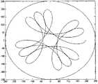
当直流伺服电机102和内置编码器伺服电机201速度匹配合适后,磁电管中心点运动轨迹如图5所示,花瓣形运动轨迹可以保证刻蚀跑道在靶材表面实现均匀地扫描,研究磁电管中心点的运动速度后发现,其运动速度如图6所示,发生周期性变化,最大值与最小值之间约为3∶1,最大值发生在轨迹线较密区域,使磁电管迅速通过该区域,避免靶材被过度刻蚀,最小值发生在轨迹线较疏区域,使磁电管缓慢通过该区域,使靶材得到充分刻蚀,这有助于进一步提高靶材的利用率。另外,还可以通过调节两电机的转速,使轨迹线形状与疏密程度实现可调,如图7、图8所示,为了清晰起见我们只取部分花瓣予以说明,图7的花瓣较图8更为稀疏,这种可调性使我们发明的装置可以用在不同的场合,通过合理调节两电机的转速,实现具体问题的最优化解。When the speeds of the
另一个双电机方案为:一个电机旋转,另外一个电机直线运动实现偏心可调。这两种方案有着本质的区别,双电机旋转方案实现的是行星机构运动,一个电机旋转另外一个电机直线运动方案实现的是可调偏心的旋转运动。双电机旋转方案实现特定复杂运动无需繁琐和频繁的电机调控,方便了使用的同时,尽可能减少了设备的故障率,使得本发明更具优势。Another dual-motor solution is: one motor rotates, and the other motor moves linearly to realize eccentric adjustment. There are essential differences between the two schemes. The dual-motor rotation scheme realizes the motion of the planetary mechanism, and the one motor rotation and the other motor linear motion scheme realizes the rotary motion with adjustable eccentricity. The dual-motor rotation scheme realizes specific complex motion without cumbersome and frequent motor regulation, which facilitates use and reduces the failure rate of equipment as much as possible, making the present invention more advantageous.
以上实施方式仅用于说明本发明,而并非对本发明的限制,有关技术领域的普通技术人员,在不脱离本发明的精神和范围的情况下,还可以做出各种变化和变型。The above embodiments are only used to illustrate the present invention, rather than to limit the present invention. Those of ordinary skill in the relevant technical fields can make various changes and modifications without departing from the spirit and scope of the present invention.
Claims (2)
Translated fromChinesePriority Applications (1)
| Application Number | Priority Date | Filing Date | Title |
|---|---|---|---|
| CN2010105886256ACN102074446B (en) | 2010-12-08 | 2010-12-08 | Magnetron with adjustable compound trace |
Applications Claiming Priority (1)
| Application Number | Priority Date | Filing Date | Title |
|---|---|---|---|
| CN2010105886256ACN102074446B (en) | 2010-12-08 | 2010-12-08 | Magnetron with adjustable compound trace |
Publications (2)
| Publication Number | Publication Date |
|---|---|
| CN102074446Atrue CN102074446A (en) | 2011-05-25 |
| CN102074446B CN102074446B (en) | 2012-07-25 |
Family
ID=44032945
Family Applications (1)
| Application Number | Title | Priority Date | Filing Date |
|---|---|---|---|
| CN2010105886256AExpired - Fee RelatedCN102074446B (en) | 2010-12-08 | 2010-12-08 | Magnetron with adjustable compound trace |
Country Status (1)
| Country | Link |
|---|---|
| CN (1) | CN102074446B (en) |
Cited By (3)
| Publication number | Priority date | Publication date | Assignee | Title |
|---|---|---|---|---|
| CN103184420A (en)* | 2011-12-28 | 2013-07-03 | 北京北方微电子基地设备工艺研究中心有限责任公司 | Scanning mechanism for driving magnetron, magnetron sputtering source and magnetron sputtering equipment |
| CN103422065A (en)* | 2012-05-16 | 2013-12-04 | 北京北方微电子基地设备工艺研究中心有限责任公司 | Magnetron sputtering device and magnetron control method |
| CN113699493A (en)* | 2021-08-30 | 2021-11-26 | 北京航空航天大学合肥创新研究院(北京航空航天大学合肥研究生院) | Cluster beam deposition equipment for realizing wide-width nanoparticle beam |
Families Citing this family (1)
| Publication number | Priority date | Publication date | Assignee | Title |
|---|---|---|---|---|
| CN103924200B (en) | 2013-12-30 | 2017-07-04 | 上海天马有机发光显示技术有限公司 | A kind of film deposition apparatus |
Citations (4)
| Publication number | Priority date | Publication date | Assignee | Title |
|---|---|---|---|---|
| JPS60197874A (en)* | 1984-03-21 | 1985-10-07 | Shinku Kikai Kogyo Kk | Magnetron sputtering device |
| US20030150712A1 (en)* | 2002-02-13 | 2003-08-14 | Reiter Jeffrey Shane | System and method for controlling thin film defects |
| CN1890399A (en)* | 2003-12-12 | 2007-01-03 | 应用材料公司 | Mechanism for varying the spacing between sputter magnetron and target |
| CN101410546A (en)* | 2006-03-28 | 2009-04-15 | 贝卡尔特股份有限公司 | Sputtering apparatus |
- 2010
- 2010-12-08CNCN2010105886256Apatent/CN102074446B/ennot_activeExpired - Fee Related
Patent Citations (4)
| Publication number | Priority date | Publication date | Assignee | Title |
|---|---|---|---|---|
| JPS60197874A (en)* | 1984-03-21 | 1985-10-07 | Shinku Kikai Kogyo Kk | Magnetron sputtering device |
| US20030150712A1 (en)* | 2002-02-13 | 2003-08-14 | Reiter Jeffrey Shane | System and method for controlling thin film defects |
| CN1890399A (en)* | 2003-12-12 | 2007-01-03 | 应用材料公司 | Mechanism for varying the spacing between sputter magnetron and target |
| CN101410546A (en)* | 2006-03-28 | 2009-04-15 | 贝卡尔特股份有限公司 | Sputtering apparatus |
Cited By (6)
| Publication number | Priority date | Publication date | Assignee | Title |
|---|---|---|---|---|
| CN103184420A (en)* | 2011-12-28 | 2013-07-03 | 北京北方微电子基地设备工艺研究中心有限责任公司 | Scanning mechanism for driving magnetron, magnetron sputtering source and magnetron sputtering equipment |
| CN103184420B (en)* | 2011-12-28 | 2014-12-17 | 北京北方微电子基地设备工艺研究中心有限责任公司 | Scanning mechanism for driving magnetron, magnetron sputtering source and magnetron sputtering equipment |
| CN103422065A (en)* | 2012-05-16 | 2013-12-04 | 北京北方微电子基地设备工艺研究中心有限责任公司 | Magnetron sputtering device and magnetron control method |
| CN103422065B (en)* | 2012-05-16 | 2016-08-31 | 北京北方微电子基地设备工艺研究中心有限责任公司 | magnetron sputtering apparatus and magnetron control method |
| CN113699493A (en)* | 2021-08-30 | 2021-11-26 | 北京航空航天大学合肥创新研究院(北京航空航天大学合肥研究生院) | Cluster beam deposition equipment for realizing wide-width nanoparticle beam |
| CN113699493B (en)* | 2021-08-30 | 2023-10-10 | 北京航空航天大学合肥创新研究院(北京航空航天大学合肥研究生院) | Cluster beam deposition equipment for realizing wide nanoparticle beam |
Also Published As
| Publication number | Publication date |
|---|---|
| CN102074446B (en) | 2012-07-25 |
Similar Documents
| Publication | Publication Date | Title |
|---|---|---|
| TWI496927B (en) | Physical vapor deposition system, magnetron for a physical vapor deposition system, and method for operating a magnetron to provide an adjustable symmetric magnetic track | |
| KR20040111676A (en) | Planetary magnetron | |
| KR20080038056A (en) | Position Control Dual Magnetron | |
| KR20150123266A (en) | Configurable variable position closed track magnetron | |
| CN101447274B (en) | Magnetic circuit mechanism, magnetron sputtering cathode with same and manufacturing method | |
| CN107955938B (en) | Vacuum reaction magnetron sputtering coating device and method for inner cavity of engine cylinder sleeve | |
| CN102074446B (en) | Magnetron with adjustable compound trace | |
| CN109778136A (en) | The method that diamond-like coating is prepared using hot electron plasma technology | |
| CN102400107A (en) | Magnetron sputtering source and magnetron sputtering device | |
| JP4213777B2 (en) | Sputtering apparatus and method | |
| CN109576652A (en) | Arc ion coating device | |
| CN102234776A (en) | Magnetron sputtering apparatus | |
| CN1718847A (en) | A pair of target twin magnetron sputtering ion plating deposition device | |
| KR20130112057A (en) | Magnetron source, magnetron sputtering device and magnetron sputtering method | |
| CN209307479U (en) | A vacuum coating machine integrating ion etching, multi-arc ion and magnetron sputtering | |
| CN110093589B (en) | Vacuum magnetron sputtering coating device for preparing graded neutral density filter | |
| CN102064076A (en) | Eccentricity-variable magnetron | |
| CN103924200B (en) | A kind of film deposition apparatus | |
| CN110911263B (en) | Magnetic field distribution homogenizing device for magnetron sputtering process chamber | |
| CN118136479A (en) | Magnetic control device, magnetron and magnetron sputtering equipment | |
| CN117626197A (en) | New forms of energy battery coating film equipment | |
| CN103147056A (en) | Moving field vacuum coating magnetron sputtering source | |
| CN114032516B (en) | Magnetic source module for magnetron sputtering equipment and magnetron sputtering equipment | |
| JP2000319780A (en) | Sputtering cathode and magnetron type sputtering device equipped with the same | |
| JP6265534B2 (en) | Sputtering cathode |
Legal Events
| Date | Code | Title | Description |
|---|---|---|---|
| C06 | Publication | ||
| PB01 | Publication | ||
| C10 | Entry into substantive examination | ||
| SE01 | Entry into force of request for substantive examination | ||
| C14 | Grant of patent or utility model | ||
| GR01 | Patent grant | ||
| CF01 | Termination of patent right due to non-payment of annual fee | Granted publication date:20120725 Termination date:20171208 | |
| CF01 | Termination of patent right due to non-payment of annual fee |