CN102069729A - Control apparatus for electric automobile - Google Patents
Control apparatus for electric automobileDownload PDFInfo
- Publication number
- CN102069729A CN102069729ACN201010557505XACN201010557505ACN102069729ACN 102069729 ACN102069729 ACN 102069729ACN 201010557505X ACN201010557505X ACN 201010557505XACN 201010557505 ACN201010557505 ACN 201010557505ACN 102069729 ACN102069729 ACN 102069729A
- Authority
- CN
- China
- Prior art keywords
- electric motor
- motor
- clutch mechanism
- state
- control
- Prior art date
- Legal status (The legal status is an assumption and is not a legal conclusion. Google has not performed a legal analysis and makes no representation as to the accuracy of the status listed.)
- Granted
Links
Images


Classifications
- B—PERFORMING OPERATIONS; TRANSPORTING
- B60—VEHICLES IN GENERAL
- B60L—PROPULSION OF ELECTRICALLY-PROPELLED VEHICLES; SUPPLYING ELECTRIC POWER FOR AUXILIARY EQUIPMENT OF ELECTRICALLY-PROPELLED VEHICLES; ELECTRODYNAMIC BRAKE SYSTEMS FOR VEHICLES IN GENERAL; MAGNETIC SUSPENSION OR LEVITATION FOR VEHICLES; MONITORING OPERATING VARIABLES OF ELECTRICALLY-PROPELLED VEHICLES; ELECTRIC SAFETY DEVICES FOR ELECTRICALLY-PROPELLED VEHICLES
- B60L58/00—Methods or circuit arrangements for monitoring or controlling batteries or fuel cells, specially adapted for electric vehicles
- B60L58/10—Methods or circuit arrangements for monitoring or controlling batteries or fuel cells, specially adapted for electric vehicles for monitoring or controlling batteries
- B60L58/12—Methods or circuit arrangements for monitoring or controlling batteries or fuel cells, specially adapted for electric vehicles for monitoring or controlling batteries responding to state of charge [SoC]
- B—PERFORMING OPERATIONS; TRANSPORTING
- B60—VEHICLES IN GENERAL
- B60K—ARRANGEMENT OR MOUNTING OF PROPULSION UNITS OR OF TRANSMISSIONS IN VEHICLES; ARRANGEMENT OR MOUNTING OF PLURAL DIVERSE PRIME-MOVERS IN VEHICLES; AUXILIARY DRIVES FOR VEHICLES; INSTRUMENTATION OR DASHBOARDS FOR VEHICLES; ARRANGEMENTS IN CONNECTION WITH COOLING, AIR INTAKE, GAS EXHAUST OR FUEL SUPPLY OF PROPULSION UNITS IN VEHICLES
- B60K6/00—Arrangement or mounting of plural diverse prime-movers for mutual or common propulsion, e.g. hybrid propulsion systems comprising electric motors and internal combustion engines
- B60K6/20—Arrangement or mounting of plural diverse prime-movers for mutual or common propulsion, e.g. hybrid propulsion systems comprising electric motors and internal combustion engines the prime-movers consisting of electric motors and internal combustion engines, e.g. HEVs
- B60K6/22—Arrangement or mounting of plural diverse prime-movers for mutual or common propulsion, e.g. hybrid propulsion systems comprising electric motors and internal combustion engines the prime-movers consisting of electric motors and internal combustion engines, e.g. HEVs characterised by apparatus, components or means specially adapted for HEVs
- B60K6/38—Arrangement or mounting of plural diverse prime-movers for mutual or common propulsion, e.g. hybrid propulsion systems comprising electric motors and internal combustion engines the prime-movers consisting of electric motors and internal combustion engines, e.g. HEVs characterised by apparatus, components or means specially adapted for HEVs characterised by the driveline clutches
- B60K6/387—Actuated clutches, i.e. clutches engaged or disengaged by electric, hydraulic or mechanical actuating means
- B—PERFORMING OPERATIONS; TRANSPORTING
- B60—VEHICLES IN GENERAL
- B60K—ARRANGEMENT OR MOUNTING OF PROPULSION UNITS OR OF TRANSMISSIONS IN VEHICLES; ARRANGEMENT OR MOUNTING OF PLURAL DIVERSE PRIME-MOVERS IN VEHICLES; AUXILIARY DRIVES FOR VEHICLES; INSTRUMENTATION OR DASHBOARDS FOR VEHICLES; ARRANGEMENTS IN CONNECTION WITH COOLING, AIR INTAKE, GAS EXHAUST OR FUEL SUPPLY OF PROPULSION UNITS IN VEHICLES
- B60K6/00—Arrangement or mounting of plural diverse prime-movers for mutual or common propulsion, e.g. hybrid propulsion systems comprising electric motors and internal combustion engines
- B60K6/20—Arrangement or mounting of plural diverse prime-movers for mutual or common propulsion, e.g. hybrid propulsion systems comprising electric motors and internal combustion engines the prime-movers consisting of electric motors and internal combustion engines, e.g. HEVs
- B60K6/42—Arrangement or mounting of plural diverse prime-movers for mutual or common propulsion, e.g. hybrid propulsion systems comprising electric motors and internal combustion engines the prime-movers consisting of electric motors and internal combustion engines, e.g. HEVs characterised by the architecture of the hybrid electric vehicle
- B60K6/48—Parallel type
- B—PERFORMING OPERATIONS; TRANSPORTING
- B60—VEHICLES IN GENERAL
- B60L—PROPULSION OF ELECTRICALLY-PROPELLED VEHICLES; SUPPLYING ELECTRIC POWER FOR AUXILIARY EQUIPMENT OF ELECTRICALLY-PROPELLED VEHICLES; ELECTRODYNAMIC BRAKE SYSTEMS FOR VEHICLES IN GENERAL; MAGNETIC SUSPENSION OR LEVITATION FOR VEHICLES; MONITORING OPERATING VARIABLES OF ELECTRICALLY-PROPELLED VEHICLES; ELECTRIC SAFETY DEVICES FOR ELECTRICALLY-PROPELLED VEHICLES
- B60L50/00—Electric propulsion with power supplied within the vehicle
- B60L50/10—Electric propulsion with power supplied within the vehicle using propulsion power supplied by engine-driven generators, e.g. generators driven by combustion engines
- B60L50/15—Electric propulsion with power supplied within the vehicle using propulsion power supplied by engine-driven generators, e.g. generators driven by combustion engines with additional electric power supply
- B—PERFORMING OPERATIONS; TRANSPORTING
- B60—VEHICLES IN GENERAL
- B60W—CONJOINT CONTROL OF VEHICLE SUB-UNITS OF DIFFERENT TYPE OR DIFFERENT FUNCTION; CONTROL SYSTEMS SPECIALLY ADAPTED FOR HYBRID VEHICLES; ROAD VEHICLE DRIVE CONTROL SYSTEMS FOR PURPOSES NOT RELATED TO THE CONTROL OF A PARTICULAR SUB-UNIT
- B60W10/00—Conjoint control of vehicle sub-units of different type or different function
- B60W10/02—Conjoint control of vehicle sub-units of different type or different function including control of driveline clutches
- B—PERFORMING OPERATIONS; TRANSPORTING
- B60—VEHICLES IN GENERAL
- B60W—CONJOINT CONTROL OF VEHICLE SUB-UNITS OF DIFFERENT TYPE OR DIFFERENT FUNCTION; CONTROL SYSTEMS SPECIALLY ADAPTED FOR HYBRID VEHICLES; ROAD VEHICLE DRIVE CONTROL SYSTEMS FOR PURPOSES NOT RELATED TO THE CONTROL OF A PARTICULAR SUB-UNIT
- B60W10/00—Conjoint control of vehicle sub-units of different type or different function
- B60W10/04—Conjoint control of vehicle sub-units of different type or different function including control of propulsion units
- B60W10/08—Conjoint control of vehicle sub-units of different type or different function including control of propulsion units including control of electric propulsion units, e.g. motors or generators
- B—PERFORMING OPERATIONS; TRANSPORTING
- B60—VEHICLES IN GENERAL
- B60W—CONJOINT CONTROL OF VEHICLE SUB-UNITS OF DIFFERENT TYPE OR DIFFERENT FUNCTION; CONTROL SYSTEMS SPECIALLY ADAPTED FOR HYBRID VEHICLES; ROAD VEHICLE DRIVE CONTROL SYSTEMS FOR PURPOSES NOT RELATED TO THE CONTROL OF A PARTICULAR SUB-UNIT
- B60W20/00—Control systems specially adapted for hybrid vehicles
- B60W20/10—Controlling the power contribution of each of the prime movers to meet required power demand
- B60W20/15—Control strategies specially adapted for achieving a particular effect
- B—PERFORMING OPERATIONS; TRANSPORTING
- B60—VEHICLES IN GENERAL
- B60L—PROPULSION OF ELECTRICALLY-PROPELLED VEHICLES; SUPPLYING ELECTRIC POWER FOR AUXILIARY EQUIPMENT OF ELECTRICALLY-PROPELLED VEHICLES; ELECTRODYNAMIC BRAKE SYSTEMS FOR VEHICLES IN GENERAL; MAGNETIC SUSPENSION OR LEVITATION FOR VEHICLES; MONITORING OPERATING VARIABLES OF ELECTRICALLY-PROPELLED VEHICLES; ELECTRIC SAFETY DEVICES FOR ELECTRICALLY-PROPELLED VEHICLES
- B60L2240/00—Control parameters of input or output; Target parameters
- B60L2240/40—Drive Train control parameters
- B60L2240/42—Drive Train control parameters related to electric machines
- B60L2240/421—Speed
- B—PERFORMING OPERATIONS; TRANSPORTING
- B60—VEHICLES IN GENERAL
- B60W—CONJOINT CONTROL OF VEHICLE SUB-UNITS OF DIFFERENT TYPE OR DIFFERENT FUNCTION; CONTROL SYSTEMS SPECIALLY ADAPTED FOR HYBRID VEHICLES; ROAD VEHICLE DRIVE CONTROL SYSTEMS FOR PURPOSES NOT RELATED TO THE CONTROL OF A PARTICULAR SUB-UNIT
- B60W20/00—Control systems specially adapted for hybrid vehicles
- B—PERFORMING OPERATIONS; TRANSPORTING
- B60—VEHICLES IN GENERAL
- B60W—CONJOINT CONTROL OF VEHICLE SUB-UNITS OF DIFFERENT TYPE OR DIFFERENT FUNCTION; CONTROL SYSTEMS SPECIALLY ADAPTED FOR HYBRID VEHICLES; ROAD VEHICLE DRIVE CONTROL SYSTEMS FOR PURPOSES NOT RELATED TO THE CONTROL OF A PARTICULAR SUB-UNIT
- B60W2510/00—Input parameters relating to a particular sub-units
- B60W2510/02—Clutches
- B60W2510/0208—Clutch engagement state, e.g. engaged or disengaged
- B—PERFORMING OPERATIONS; TRANSPORTING
- B60—VEHICLES IN GENERAL
- B60W—CONJOINT CONTROL OF VEHICLE SUB-UNITS OF DIFFERENT TYPE OR DIFFERENT FUNCTION; CONTROL SYSTEMS SPECIALLY ADAPTED FOR HYBRID VEHICLES; ROAD VEHICLE DRIVE CONTROL SYSTEMS FOR PURPOSES NOT RELATED TO THE CONTROL OF A PARTICULAR SUB-UNIT
- B60W2520/00—Input parameters relating to overall vehicle dynamics
- B60W2520/10—Longitudinal speed
- B—PERFORMING OPERATIONS; TRANSPORTING
- B60—VEHICLES IN GENERAL
- B60W—CONJOINT CONTROL OF VEHICLE SUB-UNITS OF DIFFERENT TYPE OR DIFFERENT FUNCTION; CONTROL SYSTEMS SPECIALLY ADAPTED FOR HYBRID VEHICLES; ROAD VEHICLE DRIVE CONTROL SYSTEMS FOR PURPOSES NOT RELATED TO THE CONTROL OF A PARTICULAR SUB-UNIT
- B60W2710/00—Output or target parameters relating to a particular sub-units
- B60W2710/08—Electric propulsion units
- B60W2710/081—Speed
- Y—GENERAL TAGGING OF NEW TECHNOLOGICAL DEVELOPMENTS; GENERAL TAGGING OF CROSS-SECTIONAL TECHNOLOGIES SPANNING OVER SEVERAL SECTIONS OF THE IPC; TECHNICAL SUBJECTS COVERED BY FORMER USPC CROSS-REFERENCE ART COLLECTIONS [XRACs] AND DIGESTS
- Y02—TECHNOLOGIES OR APPLICATIONS FOR MITIGATION OR ADAPTATION AGAINST CLIMATE CHANGE
- Y02T—CLIMATE CHANGE MITIGATION TECHNOLOGIES RELATED TO TRANSPORTATION
- Y02T10/00—Road transport of goods or passengers
- Y02T10/60—Other road transportation technologies with climate change mitigation effect
- Y02T10/62—Hybrid vehicles
- Y—GENERAL TAGGING OF NEW TECHNOLOGICAL DEVELOPMENTS; GENERAL TAGGING OF CROSS-SECTIONAL TECHNOLOGIES SPANNING OVER SEVERAL SECTIONS OF THE IPC; TECHNICAL SUBJECTS COVERED BY FORMER USPC CROSS-REFERENCE ART COLLECTIONS [XRACs] AND DIGESTS
- Y02—TECHNOLOGIES OR APPLICATIONS FOR MITIGATION OR ADAPTATION AGAINST CLIMATE CHANGE
- Y02T—CLIMATE CHANGE MITIGATION TECHNOLOGIES RELATED TO TRANSPORTATION
- Y02T10/00—Road transport of goods or passengers
- Y02T10/60—Other road transportation technologies with climate change mitigation effect
- Y02T10/64—Electric machine technologies in electromobility
- Y—GENERAL TAGGING OF NEW TECHNOLOGICAL DEVELOPMENTS; GENERAL TAGGING OF CROSS-SECTIONAL TECHNOLOGIES SPANNING OVER SEVERAL SECTIONS OF THE IPC; TECHNICAL SUBJECTS COVERED BY FORMER USPC CROSS-REFERENCE ART COLLECTIONS [XRACs] AND DIGESTS
- Y02—TECHNOLOGIES OR APPLICATIONS FOR MITIGATION OR ADAPTATION AGAINST CLIMATE CHANGE
- Y02T—CLIMATE CHANGE MITIGATION TECHNOLOGIES RELATED TO TRANSPORTATION
- Y02T10/00—Road transport of goods or passengers
- Y02T10/60—Other road transportation technologies with climate change mitigation effect
- Y02T10/70—Energy storage systems for electromobility, e.g. batteries
- Y—GENERAL TAGGING OF NEW TECHNOLOGICAL DEVELOPMENTS; GENERAL TAGGING OF CROSS-SECTIONAL TECHNOLOGIES SPANNING OVER SEVERAL SECTIONS OF THE IPC; TECHNICAL SUBJECTS COVERED BY FORMER USPC CROSS-REFERENCE ART COLLECTIONS [XRACs] AND DIGESTS
- Y02—TECHNOLOGIES OR APPLICATIONS FOR MITIGATION OR ADAPTATION AGAINST CLIMATE CHANGE
- Y02T—CLIMATE CHANGE MITIGATION TECHNOLOGIES RELATED TO TRANSPORTATION
- Y02T10/00—Road transport of goods or passengers
- Y02T10/60—Other road transportation technologies with climate change mitigation effect
- Y02T10/7072—Electromobility specific charging systems or methods for batteries, ultracapacitors, supercapacitors or double-layer capacitors
- Y—GENERAL TAGGING OF NEW TECHNOLOGICAL DEVELOPMENTS; GENERAL TAGGING OF CROSS-SECTIONAL TECHNOLOGIES SPANNING OVER SEVERAL SECTIONS OF THE IPC; TECHNICAL SUBJECTS COVERED BY FORMER USPC CROSS-REFERENCE ART COLLECTIONS [XRACs] AND DIGESTS
- Y02—TECHNOLOGIES OR APPLICATIONS FOR MITIGATION OR ADAPTATION AGAINST CLIMATE CHANGE
- Y02T—CLIMATE CHANGE MITIGATION TECHNOLOGIES RELATED TO TRANSPORTATION
- Y02T10/00—Road transport of goods or passengers
- Y02T10/60—Other road transportation technologies with climate change mitigation effect
- Y02T10/72—Electric energy management in electromobility
Landscapes
- Engineering & Computer Science (AREA)
- Transportation (AREA)
- Mechanical Engineering (AREA)
- Chemical & Material Sciences (AREA)
- Combustion & Propulsion (AREA)
- Power Engineering (AREA)
- Sustainable Energy (AREA)
- Life Sciences & Earth Sciences (AREA)
- Sustainable Development (AREA)
- Automation & Control Theory (AREA)
- Electric Propulsion And Braking For Vehicles (AREA)
- Hybrid Electric Vehicles (AREA)
- Hydraulic Clutches, Magnetic Clutches, Fluid Clutches, And Fluid Joints (AREA)
Abstract
Translated fromChinese
Description
Translated fromChinese技术领域technical field
本发明涉及一种具有与驱动轮连结的电动机的电动汽车的控制装置。The present invention relates to a control device for an electric vehicle having an electric motor connected to drive wheels.
背景技术Background technique
当前正在开发将发动机及电动机作为动力源的混合动力型电动汽车、以及仅将电动机作为动力源的电动汽车。上述电动汽车所搭载的电动机与驱动轮连结,电动机的转速与车速联动。即,由于在高车速区域,电动机的转速增加,所以有可能从电动机产生过大的感应电压。因此,提出了一种电动汽车,其通过在驱动轮和电动机之间设置离合器机构,从而在高车速时,将电动机与驱动轮隔断(例如,参照专利文献1及2)。由此,可以防止电动机的超速旋转,可以防止产生过大的感应电压。Currently, a hybrid electric vehicle using an engine and an electric motor as a power source, and an electric vehicle using only an electric motor as a power source are being developed. The electric motor mounted on the above-mentioned electric vehicle is connected to the drive wheels, and the rotational speed of the electric motor is linked to the vehicle speed. That is, since the rotational speed of the electric motor increases in the high vehicle speed region, there is a possibility that an excessive induced voltage is generated from the electric motor. Therefore, electric vehicles have been proposed that provide a clutch mechanism between the driving wheels and the electric motor to disconnect the electric motor from the driving wheels at high vehicle speeds (for example, refer to Patent Documents 1 and 2). Thereby, over-rotation of the motor can be prevented, and generation of excessive induced voltage can be prevented.
专利文献1:日本特开2007-331632号公报Patent Document 1: Japanese Patent Laid-Open No. 2007-331632
专利文献2:日本特开2008-239041号公报Patent Document 2: Japanese Patent Laid-Open No. 2008-239041
发明内容Contents of the invention
但是,在专利文献1及2所记载的电动汽车中,由于在高车速时电动机停止,所以无法发电。由此,如果长时间高速巡航时一直将离合器机构断开,则有可能由于持续放电而导致电池的电力枯竭、以及由于再生不足而导致电动汽车的能量转换效率降低。However, in the electric vehicles described in
本发明的目的在于,在将离合器机构断开的高车速区域中,利用电动机进行发电。An object of the present invention is to generate electricity using an electric motor in a high vehicle speed region in which a clutch mechanism is disengaged.
本发明的电动汽车的控制装置是具有与驱动轮连结的电动机的电动汽车的控制装置,其特征在于,具有:离合器机构,其设置在所述驱动轮和所述电动机之间,在高车速区域,将所述电动机与所述驱动轮隔断;以及离合器控制单元,其在高车速区域中对所述电动机进行发电控制时,将所述离合器机构控制为滑动状态,在高车速区域中对所述电动机进行发电控制时,将电动机转速抑制为小于或等于规定的上限转速。A control device for an electric vehicle according to the present invention is a control device for an electric vehicle having a motor connected to a drive wheel, and is characterized in that it has a clutch mechanism provided between the drive wheel and the motor, , isolating the motor from the drive wheels; and a clutch control unit, which controls the clutch mechanism to slip when performing power generation control on the motor in a high vehicle speed region, and controls the clutch mechanism in a high vehicle speed region. When the electric motor performs power generation control, the motor rotation speed is suppressed to be less than or equal to a predetermined upper limit rotation speed.
本发明的电动汽车的控制装置的特征在于,具有控制所述电动机的动作状态的电动机控制单元,在高车速区域中对所述电动机进行发电控制时,所述电动机控制单元执行转速控制,将电动机转速保持为规定的目标转速。The control device for an electric vehicle according to the present invention is characterized in that it includes a motor control unit for controlling the operating state of the electric motor, and when the electric motor is controlled to generate electricity in a high vehicle speed range, the motor control unit executes rotational speed control to turn the electric motor The rotational speed is maintained at the prescribed target rotational speed.
本发明的电动汽车的控制装置的特征在于,在高车速区域中对所述电动机进行发电控制时,所述电动机控制单元使反馈控制的增益常数比通常时高。In the control device for an electric vehicle according to the present invention, when performing power generation control on the electric motor in a high vehicle speed range, the electric motor control means makes a gain constant of the feedback control higher than that in a normal state.
本发明的电动汽车的控制装置的特征在于,在高车速区域中对所述电动机进行发电控制时,所述离合器控制单元使所述离合器机构在滑动状态和断开状态之间交互切换。The control device for an electric vehicle according to the present invention is characterized in that the clutch control means alternately switches the clutch mechanism between a slip state and a disengaged state when the electric motor is under power generation control in a high vehicle speed range.
发明的效果The effect of the invention
根据本发明,由于在将电动机与驱动轮断开的高车速区域中,将离合器机构控制为滑动状态,所以可以在高车速区域中,在将电动机转速抑制为小于或等于上限转速的同时,使电动机发电。According to the present invention, since the clutch mechanism is controlled to be in a slipping state in the high vehicle speed region in which the electric motor is disconnected from the drive wheels, it is possible to suppress the motor rotation speed to be less than or equal to the upper limit rotation speed in the high vehicle speed region, and to use the Electric motors generate electricity.
附图说明Description of drawings
图1是表示混合动力车辆的概略图。FIG. 1 is a schematic diagram showing a hybrid vehicle.
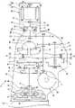
图2是表示混合动力车辆所搭载的动力单元的简图。FIG. 2 is a schematic diagram showing a power unit mounted on a hybrid vehicle.
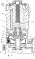
图3是放大表示动力单元的离合器机构的剖面图。Fig. 3 is an enlarged sectional view showing a clutch mechanism of the power unit.
图4是表示高车速区域中的电动发电机及离合器机构的动作状态的说明图。FIG. 4 is an explanatory view showing the operating state of a motor generator and a clutch mechanism in a high vehicle speed range.
图5是表示高车速区域中的电动发电机及离合器机构的动作状态的说明图。FIG. 5 is an explanatory view showing the operating state of a motor generator and a clutch mechanism in a high vehicle speed range.
具体实施方式Detailed ways
下面,基于附图,详细说明本发明的实施方式。图1是表示混合动力车辆10的概略图。在该混合动力车辆10中,设置有作为本发明的一个实施方式的电动汽车的控制装置。如图1所示,在车身上纵置搭载有动力单元11。在该动力单元11的一端部组装有发动机12,在动力单元11的另一端部组装有电动发电机(电动机)13。在动力单元11内组装有无级变速器14及差动机构15,发动机动力及电动机动力经由差动机构15传递至驱动轮16。Hereinafter, embodiments of the present invention will be described in detail based on the drawings. FIG. 1 is a schematic diagram showing a
为了向电动发电机13供给电力,在混合动力车辆10中搭载有高电压电池(例如锂离子电池)20。在高电压电池20和电动发电机13之间设置逆变器21,该逆变器21由开关元件等构成。在将电动发电机13作为电动机使用时,来自高电压电池20的直流电力经由逆变器21变换为电动发电机13用的交流电力。另一方面,在将电动发电机13作为发电机使用时,来自电动发电机13的交流电力经由逆变器21变换为高电压电池20用的直流电力。另外,高电压电池20经由DC/DC转换器22与低电压电池(例如铅蓄电池)23连接,从高电压电池20经由转换器22向低电压电池23供给电力。该低电压电池23作为逆变器21、转换器22、后述的各种控制单元24~26的电源起作用,并且,作为未图示的空调设备及顶灯等的电源起作用。A high-voltage battery (for example, a lithium-ion battery) 20 is mounted on the
另外,为了集中控制混合动力车辆10,在混合动力车辆10中设置有车辆控制单元24。向车辆控制单元24输入车速及加速器开度等各种信息,基于这些信息,车辆控制单元24向逆变器21及转换器22等输出控制信号。另外,为了控制高电压电池20的充放电,在混合动力车辆10中设置有电池控制单元25。该电池控制单元25控制高电压电池20的电压及电流,并且基于电压、电流、温度等,计算表示高电压电池20的电力余量的充电状态SOC。此外,为了控制发动机转速及发动机扭矩,在混合动力车辆10中设置有发动机控制单元26。这些控制单元24~26由微型计算机等构成,并且经由通信网络相互连接。In addition, in order to collectively control the
图2是表示混合动力车辆10所搭载的动力单元11的简图。如图2所示,在发动机12上组装有变速箱体30,在该变速箱体30中收容有无级变速器14。无级变速器14具有:主动轴31,其由发动机12驱动;以及从动轴32,其与主动轴31平行。在主动轴31上设置有主动带轮33,该主动带轮33具有固定滑轮33a和可动滑轮33b。在可动滑轮33b的背面侧分隔出主动油室34a、34b,可以通过对主动油室34a、34b内的压力进行调整而使带轮槽宽度变化。另外,在从动轴32上设置有从动带轮35,该从动带轮35具有固定滑轮35a和可动滑轮35b。在可动滑轮35b的背面侧分隔出从动油室36,可以通过对从动油室36内的压力进行调整而使带轮槽宽度变化。此外,通过使带轮33、35的槽宽度变化而使驱动链37的卷绕直径变化,由此,可以从主动轴31至从动轴32进行无级变速。FIG. 2 is a schematic diagram showing a power unit 11 mounted on a
为了向上述无级变速器14传递发动机动力,在曲轴40和主动轴31之间设置有变矩器41及前进后退切换机构42。变矩器41具有:泵叶轮43,其与曲轴40连结;以及涡轮45,其与该泵叶轮43相对,并且与涡轮轴44连结。另外,前进后退切换机构42具有双小齿轮式的行星齿轮系46、前进离合器47以及后退制动器48。通过控制前进离合器47及后退制动器48,可以切换发动机动力的传递路径而切换主动轴31的旋转方向。此外,在变速箱体30内,收容与从动轴32平行的变速输出轴49,变速输出轴49和从动轴32经由齿轮系50连结。另外,在变速输出轴49的端部固定小齿轮51,该小齿轮51与差动机构15的齿圈52啮合。由此,无级变速器14和差动机构15经由变速输出轴49连结,从无级变速器14输出的发动机动力经由变速输出轴49传递至差动机构15。In order to transmit engine power to the above-mentioned continuously
另外,在变速箱体30中组装有电动机壳体60,在电动机壳体60中收容有电动发电机13。电动发电机13具有:定子61,其固定在电动机壳体60上;以及转子62,其可自由旋转地设置在定子61的内侧。图示的电动发电机13为永磁体同步电动机(PM电动机),在定子61上卷绕有定子线圈63,在转子62上组装有永磁体。为了控制上述电动发电机13,作为电动机控制单元起作用的车辆控制单元24,基于加速器开度及电动机转速等设定目标扭矩。并且,车辆控制单元24将与目标扭矩对应的脉冲信号向逆变器21输出,逆变器21向定子线圈63的各相线供给交流电流。此外,车辆控制单元24对向各相线供给的电流值进行检测,对脉冲信号进行反馈控制,控制使得电动发电机13输出目标扭矩。此外,在电动发电机13的转子62上设置旋转变压器(resolver)等旋转位置传感64,利用该旋转位置传感器64检测转子62的旋转角度。该旋转角度用于在三相固定坐标系(u-v-w)和旋转坐标系(d-q)之间进行坐标变换。In addition, a motor case 60 is incorporated into the
另外,在电动发电机13和变速输出轴49之间设置离合器机构65及齿轮系66,电动机动力经由离合器机构65及齿轮系66传递至变速输出轴49。在这里,图3是放大表示动力单元11的离合器机构65的剖面图。如图3所示,离合器机构65具有:离合毂68,其固定在从转子62延伸的电动机轴67上;以及离合器鼓69,其与齿轮系66的驱动齿轮66a连结。在离合毂68上安装有多个摩擦片70a,在离合器鼓69上安装有多个摩擦片70b。另外,在离合器鼓69中收容活塞71,由离合器鼓69和活塞71分隔出离合器油室72。通过向该离合器油室72供给动作油,而利用油压将活塞71推出,因此,摩擦片70a、70b彼此挤压,离合器机构65切换至接合状态。另一方面,通过从离合器油室72排出动作油,而利用弹簧部件73将活塞71推回,因此,解除摩擦片70a、70b的卡合状态,离合器机构65切换至断开状态。此外,通过调整供给至离合器油室72的离合器压力,可以控制为一边使摩擦片70a、70b滑动一边传递扭矩的滑动状态。In addition, a
为了对向离合器机构65的离合器油室72的动作油供给进行控制,如图2所示,在动力单元11中设置有油泵80,其被发动机12驱动,如图1所示,在油泵80和离合器机构65之间设置有阀单元81。阀单元81由油路切换阀或压力控制阀等电磁控制阀构成,这些电磁控制阀的动作状态由作为离合器控制单元起作用的车辆控制单元24进行控制。在电动机转速小于或等于规定的上限转速的低中车速区域中,通过车辆控制单元24将离合器机构65切换至接合状态,电动发电机13与驱动轮16连结。另一方面,在电动机转速超过上限转速的高车速区域中,通过车辆控制单元24将离合器机构65切换至断开状态,将电动发电机13与驱动轮16隔断。此外,车辆控制单元24基于来自旋转位置传感器64的信号,计算电动机转速。In order to control the supply of operating oil to the
由此,在高车速区域中,由于将电动发电机13与高速旋转的驱动轮16隔断,所以可以防止电动发电机13的超速旋转,可以防止产生过大的感应电压。由此,可以将逆变器21的耐电压抑制为较低,可以降低电力控制系统的成本。另外,通过在高车速时隔断电动发电机13,可以抑制伴随着弱磁场控制导致的电力消耗,可以抑制混合动力车辆10的电力消耗。此外,通过在高车速时隔断电动发电机13,还可以抑制由于转子62的旋转阻力导致的动力损耗。Thus, in the high vehicle speed range, since the
下面,对电动发电机13的发电控制进行说明。如上述所示,从在高车速区域中保护逆变器21等的角度出发,将电动发电机13与驱动轮16隔断。但是,由于电动发电机13作为发电机起作用,所以在高车速区域中持续断开离合器机构65成为限制电动发电机13的发电动作的主要原因。即,在高速巡航时等长时间内持续断开离合器机构65的情况下,有可能因放电状态持续而导致高电压电池20及低电压电池23的电力枯竭,难以维持混合动力车辆10的行驶性能。因此,作为本发明的一个实施方式的电动汽车的控制装置,通过在高车速区域中将离合器机构65控制为滑动状态,在不会导致电动发电机13的超速旋转的状态下,进行电动发电机13的发电控制。Next, power generation control of the
图4是表示高车速区域中的电动发电机13及离合器机构65的动作状态的说明图。如图4所示,由于在低中速区域中,离合器机构65接合,所以电动机转速与车速联动而进行变化。并且,如果混合动力车辆10到达高车速区域,电动机转速超过规定的断开转速Nr(标号a),则离合器机构65切换至断开状态,将电动发电机13与驱动轮16隔断。如上述所示,在离合器机构65的断开状态下,无法利用电动发电机13进行发电,因此,高电压电池20的充电状态SOC逐渐降低。FIG. 4 is an explanatory diagram showing the operating states of the
然后,如果充电状态SOC低于规定的下限值Smin(标号b),则执行针对电动发电机13的转速控制,电动机转速保持为与上限转速Nmax相比处于低旋转侧的目标转速Nt。在该转速控制中,将反馈控制的增益常数设定为,与低中车速区域中的通常时的扭矩控制相比较高。此外,向离合器油室72供给预先设定的规定的离合器压力,使离合器机构65从断开状态切换至滑动状态。由此,从变速输出轴49向电动发电机13有限制地供给发电用扭矩,可以将电动发电机13控制为再生状态。此时,由于对电动发电机13进行转速控制,所以电动机转速不会超过上限转速Nmax。而且,由于在转速控制中,将反馈控制的增益常数设定得较高,所以可以提高电动发电机13的响应性,可以可靠地防止电动发电机13的超速旋转。并且,在伴随着发电而上升的充电状态SOC达到规定的上限值Smax的情况下(标号c),由于不需要利用电动发电机13进行发电,所以停止对电动发电机13的转速控制,使离合器机构65再次切换至断开状态。此外,电动发电机13的上限转速Nmax是所容许的电动机转速的上限值,是基于逆变器21的耐电压性能及转子62的机械强度等而设定的上限值。Then, if the state of charge SOC is lower than the predetermined lower limit value Smin (symbol b), the rotation speed control for the
这样,由于在高车速区域中,将离合器机构65控制为滑动状态,所以可以在抑制电动机转速的同时,将电动发电机13控制为再生状态(发电状态)。而且,由于控制使得电动发电机13保持目标转速Nt,所以可以可靠地防止电动发电机13的超速旋转。由此,由于在高车速区域中也可以将电动发电机13控制为再生状态,所以可以将高电压电池20的充电状态SOC保持在适当范围内,可以确保高车速区域中的混合动力车辆10的行驶性能。此外,由于可以将电动发电机13的再生范围扩大至高车速区域,所以可以提高混合动力车辆10的油耗性能。此外,由于可以将高电压电池20的充电状态SOC保持在适当范围内,所以可以省略用于对低电压电池23进行充电的交流发电机,可以实现低电压系统的简化。In this way, since the
在上述说明中,在充电状态SOC达到规定的上限值Smax时,解除离合器机构65的滑动控制,但并不限定于此。例如图4中虚线所示,在离合器接合时的电动机转速伴随着车速降低而低于上限转速Nmax的情况下(标号d),也解除对离合器机构65的滑动控制,使离合器机构65从滑动状态切换至接合状态。另外,在图4所示的情况下,断开转速Nr和目标转速Nt为相同转速,但并不限定于此,也可以设定为互不相同的转速。此外,为了抑制离合器机构65的滑动量而提高耐久性,优选将电动发电机13的目标转速Nt设定在上限转速Nmax的附近。In the above description, the slip control of the
另外,如图1及图2所示,在动力单元11中设置旋转传感器82,其对驱动齿轮66a的转速进行检测,可以利用该旋转传感器82对离合器机构65中的驱动轮侧的转速进行检测。车辆控制单元24从离合器机构65的驱动轮侧的转速减去离合器机构65的电动机侧的转速(电动机转速),从而计算离合器机构65的滑动量。另外,车辆控制单元24基于向离合器油室72供给的离合器压力,计算离合器机构65的传递扭矩。此外,车辆控制单元24将滑动量和传递扭矩相乘而计算离合器机构65的发热量,并且计算滑动控制中的发热量的累积值。然后,在发热量超过预先设定的上限值的情况、或发热量的累计值超过预先设定的上限值的情况下,车辆控制单元24解除滑动控制,将离合器机构65切换至断开状态。由此,可以预先防止离合器机构65的烧伤,可以提高离合器机构65的耐久性。In addition, as shown in FIGS. 1 and 2 , a
在上述说明中,在高车速区域中充电状态SOC降低的情况下,在将离合器机构65保持为滑动状态的基础上,将电动发电机13控制为再生状态,但并不限定于此,也可以使离合器机构65断续地在滑动状态和断开状态之间切换。在这里,图5是表示高车速区域中的电动发电机13及离合器机构65的动作状态的说明图。如图5所示,如果混合动力车辆10到达高车速区域,电动机转速超过规定的断开转速Nr(标号a),则离合器机构65切换至断开状态,将电动发电机13与驱动轮16隔断。在该离合器机构65的断开状态下,由于无法利用电动发电机13进行发电,所以高电压电池20的充电状态SOC逐渐降低。In the above description, when the state of charge SOC is lowered in the high vehicle speed range, the
然后,如果充电状态SOC低于规定的下限值Smin(标号b),则执行针对电动发电机13的转速控制,电动机转速保持为与上限转速Nmax相比处于低旋转侧的目标转速Nt。在该转速控制中,将反馈控制的增益常数设定为,比低中车速区域中的通常时的扭矩控制更高。此外,向离合器油室72供给预先设定的规定的离合器压力,使离合器机构65从断开状态切换至滑动状态。并且,在离合器机构65的滑动状态持续了规定时间后,执行离合器机构65的断续控制。该离合器机构65的断续控制是指使离合器机构65在滑动状态和断开状态之间交互切换的控制。Then, if the state of charge SOC is lower than the predetermined lower limit value Smin (symbol b), the rotation speed control for the
由此,即使在使离合器机构65在滑动状态和断开状态之间交互切换的情况下,也可以从变速输出轴49向电动发电机13供给发电用的扭矩,将电动发电机13控制为再生状态。而且,通过使离合器机构65在滑动状态和断开状态之间交互切换,可以防止离合器机构65的过度发热,可以提高离合器机构65的耐久性。另外,在断续控制中保持滑动状态或断开状态的时间是基于离合器机构65的发热量而设定的。例如,在发热量较少的情况下,将滑动状态的保持时间设定得较长,在发热量较多的情况下,将断开状态的保持时间设定得较长。此外,离合器机构65的发热量如上述所示,通过将离合器机构65的滑动量和传递扭矩相乘而进行计算。As a result, even when the
此外,可以仅在离合器机构65切换至滑动状态时使电动发电机13发电,也可以在离合器机构65在滑动状态和断开状态之间断续地切换的期间中,使电动发电机13发电。另外,在充电状态SOC达到规定的上限值Smax的情况下(标号c)、或者离合器接合时的电动机转速伴随着车速降低而低于上限转速Nmax的情况下(标号d),如上述所示,停止对电动发电机13的转速控制,将离合器机构65再次切换至断开状态。In addition, the
本发明并不限定于上述实施方式,当然可以在不脱离其主旨的范围内进行各种变更。在上述说明中,针对混合动力车辆10应用本发明,但对于仅具有电动机作为动力源的电动汽车,也可以应用本发明。另外,作为电动机举出了永磁体同步电动机,但并不限定于此,也可以是其他方式的同步电动机,也可以是感应电动机。The present invention is not limited to the above-described embodiments, and it is needless to say that various changes can be made within a range not departing from the gist. In the above description, the present invention is applied to the
Claims (4)
Translated fromChineseApplications Claiming Priority (2)
| Application Number | Priority Date | Filing Date | Title |
|---|---|---|---|
| JP2009-264011 | 2009-11-19 | ||
| JP2009264011AJP5520578B2 (en) | 2009-11-19 | 2009-11-19 | Electric vehicle control device |
Publications (2)
| Publication Number | Publication Date |
|---|---|
| CN102069729Atrue CN102069729A (en) | 2011-05-25 |
| CN102069729B CN102069729B (en) | 2015-04-01 |
Family
ID=44010778
Family Applications (1)
| Application Number | Title | Priority Date | Filing Date |
|---|---|---|---|
| CN201010557505.XAActiveCN102069729B (en) | 2009-11-19 | 2010-11-19 | Control apparatus for electric automobile |
Country Status (4)
| Country | Link |
|---|---|
| US (1) | US8430191B2 (en) |
| JP (1) | JP5520578B2 (en) |
| CN (1) | CN102069729B (en) |
| DE (1) | DE102010060629B4 (en) |
Cited By (12)
| Publication number | Priority date | Publication date | Assignee | Title |
|---|---|---|---|---|
| CN102303523A (en)* | 2011-08-26 | 2012-01-04 | 安徽巨一自动化装备有限公司 | Control method for electric vehicle power system |
| CN102303524A (en)* | 2011-08-26 | 2012-01-04 | 安徽巨一自动化装备有限公司 | Control method for electric vehicle power system with clutch device |
| CN102320253A (en)* | 2011-08-26 | 2012-01-18 | 安徽巨一自动化装备有限公司 | Control method of electric vehicle power system with multigear speed-changing box |
| CN102442223A (en)* | 2011-10-21 | 2012-05-09 | 清华大学 | Distributed driving type electric automobile failure control system based on quadratic optimization |
| CN103158570A (en)* | 2011-12-16 | 2013-06-19 | 北汽福田汽车股份有限公司 | High voltage accessory energy management method of pure electric automobile |
| CN103502071A (en)* | 2011-08-08 | 2014-01-08 | 爱信艾达株式会社 | Control device |
| CN103684168A (en)* | 2012-09-07 | 2014-03-26 | 福特全球技术公司 | Electric motor mode control |
| CN104718101A (en)* | 2012-10-11 | 2015-06-17 | 日立汽车系统株式会社 | Regeneration control device for vehicle |
| CN105189170A (en)* | 2013-11-15 | 2015-12-23 | 株式会社小松制作所 | Utility vehicle, and control method for same |
| CN107933308A (en)* | 2016-10-13 | 2018-04-20 | 上海大郡动力控制技术有限公司 | New-energy automobile high speed speed-limiting control method |
| CN109922981A (en)* | 2016-11-08 | 2019-06-21 | 奥迪股份公司 | For the power transmitting apparatus of motor vehicle, corresponding motor vehicle and method for running power transmitting apparatus |
| CN113335044A (en)* | 2021-07-22 | 2021-09-03 | 中国第一汽车股份有限公司 | Power system of electric automobile with double transmissions and control method thereof |
Families Citing this family (20)
| Publication number | Priority date | Publication date | Assignee | Title |
|---|---|---|---|---|
| JP5794525B2 (en)* | 2011-07-22 | 2015-10-14 | 東洋電産株式会社 | Battery charger for electric vehicles and rescue vehicle |
| JP2013083276A (en)* | 2011-10-06 | 2013-05-09 | Isuzu Motors Ltd | Power regeneration device mounted in vehicle, and method for controlling the same |
| JP5797123B2 (en)* | 2012-01-27 | 2015-10-21 | 富士重工業株式会社 | Vehicle and vehicle control device |
| US10072662B2 (en)* | 2013-03-14 | 2018-09-11 | Regal Beloit America, Inc. | Dynamic speed control for pump motor |
| US9333966B2 (en)* | 2013-05-02 | 2016-05-10 | Toyota Jidosha Kabushiki Kaisha | Control apparatus for hybrid vehicle |
| US9139088B2 (en)* | 2013-08-30 | 2015-09-22 | Ford Global Technologies, Llc | System and method for hybrid vehicle control during wheel slip events to limit generator speed |
| CN104071030B (en)* | 2013-12-30 | 2019-04-23 | 上海大郡动力控制技术有限公司 | A kind of control method under pure electric automobile park mode |
| JP2015131513A (en)* | 2014-01-09 | 2015-07-23 | トヨタ自動車株式会社 | Vehicle control apparatus |
| DE102014211552A1 (en)* | 2014-06-17 | 2015-12-31 | Continental Automotive Gmbh | Control of a coupling device for optimizing a recuperation of an electric motor |
| CN104442436B (en)* | 2014-10-09 | 2017-08-25 | 惠州市亿能电子有限公司 | A kind of battery power control method of suitable trolley coach |
| JP6365469B2 (en)* | 2015-09-03 | 2018-08-01 | トヨタ自動車株式会社 | Vehicle control device |
| CN105539197A (en)* | 2015-12-15 | 2016-05-04 | 阳光电源股份有限公司 | Electric vehicle, electric vehicle motor controller and control method and device of electric vehicle motor controller |
| CN107972498A (en)* | 2016-10-21 | 2018-05-01 | 蔚来汽车有限公司 | Power distribution method and system for electric vehicle |
| CN107696868A (en)* | 2017-09-29 | 2018-02-16 | 北京新能源汽车股份有限公司 | Electric vehicle overspeed fault processing method and device and vehicle-mounted equipment |
| CN111433090B (en)* | 2017-12-04 | 2023-06-27 | 三菱自动车工业株式会社 | vehicle control unit |
| KR102370944B1 (en)* | 2017-12-12 | 2022-03-07 | 현대자동차주식회사 | Method for preventing takeoff of motor velocity for hybrid electric vehicle |
| CN110266226B (en)* | 2019-06-05 | 2021-03-30 | 武汉大学深圳研究院 | Electric vehicle energy efficiency control method based on model predictive control |
| CN112622868B (en)* | 2020-12-25 | 2022-04-19 | 中国第一汽车股份有限公司 | Dual-motor vehicle control method and device |
| US12377853B2 (en)* | 2022-06-10 | 2025-08-05 | Kawasaki Motors, Ltd. | Utility vehicle and method for controlling utility vehicle |
| JP7445062B1 (en) | 2023-06-08 | 2024-03-06 | 正成 齋藤 | An electric motor that has the ability to simultaneously generate power and generate power on its own. |
Citations (6)
| Publication number | Priority date | Publication date | Assignee | Title |
|---|---|---|---|---|
| JP2001263209A (en)* | 2000-03-21 | 2001-09-26 | Nissan Motor Co Ltd | Starting device for internal combustion engine |
| CN1819940A (en)* | 2003-08-12 | 2006-08-16 | 日产柴油机车工业株式会社 | Hybrid drive system of vehicle |
| JP2007331632A (en)* | 2006-06-16 | 2007-12-27 | Hitachi Ltd | Vehicle drive device and vehicle drive system |
| JP2008006977A (en)* | 2006-06-29 | 2008-01-17 | Honda Motor Co Ltd | Control device for hybrid vehicle |
| JP2008179263A (en)* | 2007-01-25 | 2008-08-07 | Nissan Motor Co Ltd | Vehicle driving force control device |
| JP2009208700A (en)* | 2008-03-06 | 2009-09-17 | Nissan Motor Co Ltd | Controller for hybrid car |
Family Cites Families (5)
| Publication number | Priority date | Publication date | Assignee | Title |
|---|---|---|---|---|
| JPH06101881B2 (en)* | 1986-07-10 | 1994-12-12 | 株式会社日立製作所 | Braking controller for electric vehicle |
| JP3952490B2 (en)* | 2000-03-16 | 2007-08-01 | マツダ株式会社 | Hybrid vehicle travel control device |
| JP3744414B2 (en)* | 2001-11-29 | 2006-02-08 | トヨタ自動車株式会社 | Vehicle control device |
| JP2004224110A (en)* | 2003-01-21 | 2004-08-12 | Suzuki Motor Corp | Regeneration power generation control device for hybrid vehicle |
| JP2008239041A (en) | 2007-03-28 | 2008-10-09 | Daihatsu Motor Co Ltd | Hybrid vehicle |
- 2009
- 2009-11-19JPJP2009264011Apatent/JP5520578B2/ennot_activeExpired - Fee Related
- 2010
- 2010-11-11USUS12/944,129patent/US8430191B2/enactiveActive
- 2010-11-17DEDE102010060629.4Apatent/DE102010060629B4/enactiveActive
- 2010-11-19CNCN201010557505.XApatent/CN102069729B/enactiveActive
Patent Citations (6)
| Publication number | Priority date | Publication date | Assignee | Title |
|---|---|---|---|---|
| JP2001263209A (en)* | 2000-03-21 | 2001-09-26 | Nissan Motor Co Ltd | Starting device for internal combustion engine |
| CN1819940A (en)* | 2003-08-12 | 2006-08-16 | 日产柴油机车工业株式会社 | Hybrid drive system of vehicle |
| JP2007331632A (en)* | 2006-06-16 | 2007-12-27 | Hitachi Ltd | Vehicle drive device and vehicle drive system |
| JP2008006977A (en)* | 2006-06-29 | 2008-01-17 | Honda Motor Co Ltd | Control device for hybrid vehicle |
| JP2008179263A (en)* | 2007-01-25 | 2008-08-07 | Nissan Motor Co Ltd | Vehicle driving force control device |
| JP2009208700A (en)* | 2008-03-06 | 2009-09-17 | Nissan Motor Co Ltd | Controller for hybrid car |
Cited By (20)
| Publication number | Priority date | Publication date | Assignee | Title |
|---|---|---|---|---|
| CN103502071B (en)* | 2011-08-08 | 2016-02-24 | 爱信艾达株式会社 | Control device |
| CN103502071A (en)* | 2011-08-08 | 2014-01-08 | 爱信艾达株式会社 | Control device |
| CN102303524A (en)* | 2011-08-26 | 2012-01-04 | 安徽巨一自动化装备有限公司 | Control method for electric vehicle power system with clutch device |
| CN102320253A (en)* | 2011-08-26 | 2012-01-18 | 安徽巨一自动化装备有限公司 | Control method of electric vehicle power system with multigear speed-changing box |
| CN102303523B (en)* | 2011-08-26 | 2012-12-19 | 安徽巨一自动化装备有限公司 | Control method for electric vehicle power system |
| CN102303524B (en)* | 2011-08-26 | 2012-12-19 | 安徽巨一自动化装备有限公司 | Control method for electric vehicle power system with clutch device |
| CN102303523A (en)* | 2011-08-26 | 2012-01-04 | 安徽巨一自动化装备有限公司 | Control method for electric vehicle power system |
| CN102442223A (en)* | 2011-10-21 | 2012-05-09 | 清华大学 | Distributed driving type electric automobile failure control system based on quadratic optimization |
| CN102442223B (en)* | 2011-10-21 | 2013-11-06 | 清华大学 | Distributed driving type electric automobile failure control system based on quadratic optimization |
| CN103158570A (en)* | 2011-12-16 | 2013-06-19 | 北汽福田汽车股份有限公司 | High voltage accessory energy management method of pure electric automobile |
| CN103158570B (en)* | 2011-12-16 | 2016-07-13 | 北汽福田汽车股份有限公司 | The High voltage accessory energy management of pure electric automobile |
| CN103684168A (en)* | 2012-09-07 | 2014-03-26 | 福特全球技术公司 | Electric motor mode control |
| CN104718101A (en)* | 2012-10-11 | 2015-06-17 | 日立汽车系统株式会社 | Regeneration control device for vehicle |
| CN105189170A (en)* | 2013-11-15 | 2015-12-23 | 株式会社小松制作所 | Utility vehicle, and control method for same |
| CN105189170B (en)* | 2013-11-15 | 2017-07-07 | 株式会社小松制作所 | Working truck and its control method |
| CN107933308A (en)* | 2016-10-13 | 2018-04-20 | 上海大郡动力控制技术有限公司 | New-energy automobile high speed speed-limiting control method |
| CN107933308B (en)* | 2016-10-13 | 2020-05-26 | 上海大郡动力控制技术有限公司 | High-speed limit control method for new energy automobile |
| CN109922981A (en)* | 2016-11-08 | 2019-06-21 | 奥迪股份公司 | For the power transmitting apparatus of motor vehicle, corresponding motor vehicle and method for running power transmitting apparatus |
| US11299028B2 (en) | 2016-11-08 | 2022-04-12 | Audi Ag | Drive device for a motor vehicle, corresponding motor vehicle, and method for operating a drive device |
| CN113335044A (en)* | 2021-07-22 | 2021-09-03 | 中国第一汽车股份有限公司 | Power system of electric automobile with double transmissions and control method thereof |
Also Published As
| Publication number | Publication date |
|---|---|
| US8430191B2 (en) | 2013-04-30 |
| DE102010060629B4 (en) | 2022-11-17 |
| US20110115318A1 (en) | 2011-05-19 |
| DE102010060629A1 (en) | 2011-06-22 |
| JP5520578B2 (en) | 2014-06-11 |
| CN102069729B (en) | 2015-04-01 |
| JP2011109855A (en) | 2011-06-02 |
Similar Documents
| Publication | Publication Date | Title |
|---|---|---|
| CN102069729B (en) | Control apparatus for electric automobile | |
| US9085291B2 (en) | Control system for vehicle | |
| US8992378B2 (en) | Vehicle powertrain with clutch actuator providing electrical power | |
| RU2563293C2 (en) | Hybrid vehicle and method of its control | |
| KR101241210B1 (en) | Oil pump controlling systen of hybrid vehicle and method thereof | |
| US8880263B2 (en) | Control device for hybrid vehicle | |
| US8845482B2 (en) | Hybrid power driving system and driving method of the same | |
| US10023173B2 (en) | Electromotive drive system for engine-driven vehicle | |
| US8914179B2 (en) | Power transmission device | |
| CN102407767A (en) | Drive device for hybrid vehicle | |
| CN102753414B (en) | Method of controlling hybrid vehicle motorization device and associated device | |
| CN107618352A (en) | Hybrid powertrain | |
| EP2246230B1 (en) | Method for starting a thermal engine of a hybrid vehicle | |
| US20110237387A1 (en) | Individual-powered dual CVT differential system with stabilizing device | |
| CN104853971A (en) | Control device for hybrid vehicle | |
| US10759410B2 (en) | Drive force control system for hybrid vehicle | |
| CN106042824A (en) | Hybrid vehicle split exhaust system with exhaust driven electric machine and A/C compressor | |
| JP2009137329A (en) | Control device for hybrid vehicle | |
| CN108340766A (en) | Hybrid power system, vehicle and its control method | |
| JP2011250590A (en) | Drive control device | |
| EP3922522B1 (en) | Control device for vehicle drive device | |
| JP7401022B2 (en) | Vehicle control device | |
| JP2011178285A (en) | Power transmission control device | |
| JP6365761B2 (en) | Control device for hybrid vehicle | |
| JP2018170919A (en) | Drive control device for vehicle |
Legal Events
| Date | Code | Title | Description |
|---|---|---|---|
| C06 | Publication | ||
| PB01 | Publication | ||
| C10 | Entry into substantive examination | ||
| SE01 | Entry into force of request for substantive examination | ||
| C14 | Grant of patent or utility model | ||
| GR01 | Patent grant | ||
| CP01 | Change in the name or title of a patent holder | ||
| CP01 | Change in the name or title of a patent holder | Address after:Tokyo, Japan Patentee after:Subaru Co. Address before:Tokyo, Japan Patentee before:Fuji Heavy Industries, Ltd. |