CN102068721A - manual massage breast pump - Google Patents
manual massage breast pumpDownload PDFInfo
- Publication number
- CN102068721A CN102068721ACN2011100029222ACN201110002922ACN102068721ACN 102068721 ACN102068721 ACN 102068721ACN 2011100029222 ACN2011100029222 ACN 2011100029222ACN 201110002922 ACN201110002922 ACN 201110002922ACN 102068721 ACN102068721 ACN 102068721A
- Authority
- CN
- China
- Prior art keywords
- breast
- breast pump
- milk
- handle
- cavity
- Prior art date
- Legal status (The legal status is an assumption and is not a legal conclusion. Google has not performed a legal analysis and makes no representation as to the accuracy of the status listed.)
- Pending
Links
- 210000000481breastAnatomy0.000titleclaimsabstractdescription222
- 238000000465mouldingMethods0.000claimsdescription9
- 210000003437tracheaAnatomy0.000claimsdescription9
- 230000000694effectsEffects0.000claimsdescription4
- 238000005452bendingMethods0.000claims3
- 239000011148porous materialSubstances0.000claims3
- 239000011248coating agentSubstances0.000claims2
- 238000000576coating methodMethods0.000claims2
- 238000012856packingMethods0.000claims1
- 210000004080milkAnatomy0.000abstractdescription33
- 239000008267milkSubstances0.000abstractdescription33
- 235000013336milkNutrition0.000abstractdescription33
- 230000028327secretionEffects0.000abstractdescription4
- 230000006651lactationEffects0.000abstractdescription2
- 230000011514reflexEffects0.000abstractdescription2
- VYPSYNLAJGMNEJ-UHFFFAOYSA-NSilicium dioxideChemical compoundO=[Si]=OVYPSYNLAJGMNEJ-UHFFFAOYSA-N0.000abstract2
- 239000000741silica gelSubstances0.000abstract2
- 229910002027silica gelInorganic materials0.000abstract2
- 238000001125extrusionMethods0.000abstract1
- 229920001296polysiloxanePolymers0.000description15
- 230000004308accommodationEffects0.000description6
- 239000007788liquidSubstances0.000description5
- 210000004883areolaAnatomy0.000description4
- 230000009471actionEffects0.000description3
- 230000007423decreaseEffects0.000description3
- 238000010586diagramMethods0.000description3
- 238000000034methodMethods0.000description3
- 230000005540biological transmissionEffects0.000description2
- 239000000463materialSubstances0.000description2
- 210000002445nippleAnatomy0.000description2
- 238000005086pumpingMethods0.000description2
- 230000008961swellingEffects0.000description2
- 101100325962Arabidopsis thaliana BHLH80 geneProteins0.000description1
- 230000002411adverseEffects0.000description1
- 238000006243chemical reactionMethods0.000description1
- 230000003670easy-to-cleanEffects0.000description1
- 238000009434installationMethods0.000description1
- 230000009916joint effectEffects0.000description1
- 230000007246mechanismEffects0.000description1
- 239000012528membraneSubstances0.000description1
- 238000012986modificationMethods0.000description1
- 230000004048modificationEffects0.000description1
- 231100000252nontoxicToxicity0.000description1
- 230000003000nontoxic effectEffects0.000description1
- 210000003903pelvic floorAnatomy0.000description1
- 230000008569processEffects0.000description1
- 230000001681protective effectEffects0.000description1
- 230000004936stimulating effectEffects0.000description1
- 238000009423ventilationMethods0.000description1
Images


Classifications
- A—HUMAN NECESSITIES
- A61—MEDICAL OR VETERINARY SCIENCE; HYGIENE
- A61H—PHYSICAL THERAPY APPARATUS, e.g. DEVICES FOR LOCATING OR STIMULATING REFLEX POINTS IN THE BODY; ARTIFICIAL RESPIRATION; MASSAGE; BATHING DEVICES FOR SPECIAL THERAPEUTIC OR HYGIENIC PURPOSES OR SPECIFIC PARTS OF THE BODY
- A61H9/00—Pneumatic or hydraulic massage
- A61H9/005—Pneumatic massage
- A61H9/0057—Suction
- A—HUMAN NECESSITIES
- A61—MEDICAL OR VETERINARY SCIENCE; HYGIENE
- A61M—DEVICES FOR INTRODUCING MEDIA INTO, OR ONTO, THE BODY; DEVICES FOR TRANSDUCING BODY MEDIA OR FOR TAKING MEDIA FROM THE BODY; DEVICES FOR PRODUCING OR ENDING SLEEP OR STUPOR
- A61M1/00—Suction or pumping devices for medical purposes; Devices for carrying-off, for treatment of, or for carrying-over, body-liquids; Drainage systems
- A61M1/06—Milking pumps
- A61M1/062—Pump accessories
- A61M1/064—Suction cups
- A61M1/066—Inserts therefor
- A—HUMAN NECESSITIES
- A61—MEDICAL OR VETERINARY SCIENCE; HYGIENE
- A61M—DEVICES FOR INTRODUCING MEDIA INTO, OR ONTO, THE BODY; DEVICES FOR TRANSDUCING BODY MEDIA OR FOR TAKING MEDIA FROM THE BODY; DEVICES FOR PRODUCING OR ENDING SLEEP OR STUPOR
- A61M1/00—Suction or pumping devices for medical purposes; Devices for carrying-off, for treatment of, or for carrying-over, body-liquids; Drainage systems
- A61M1/06—Milking pumps
- A61M1/069—Means for improving milking yield
- A61M1/0693—Means for improving milking yield with programmable or pre-programmed sucking patterns
- A61M1/06935—Means for improving milking yield with programmable or pre-programmed sucking patterns imitating the suckling of an infant
- A—HUMAN NECESSITIES
- A61—MEDICAL OR VETERINARY SCIENCE; HYGIENE
- A61M—DEVICES FOR INTRODUCING MEDIA INTO, OR ONTO, THE BODY; DEVICES FOR TRANSDUCING BODY MEDIA OR FOR TAKING MEDIA FROM THE BODY; DEVICES FOR PRODUCING OR ENDING SLEEP OR STUPOR
- A61M1/00—Suction or pumping devices for medical purposes; Devices for carrying-off, for treatment of, or for carrying-over, body-liquids; Drainage systems
- A61M1/06—Milking pumps
- A61M1/069—Means for improving milking yield
- A61M1/0697—Means for improving milking yield having means for massaging the breast
- A—HUMAN NECESSITIES
- A61—MEDICAL OR VETERINARY SCIENCE; HYGIENE
- A61H—PHYSICAL THERAPY APPARATUS, e.g. DEVICES FOR LOCATING OR STIMULATING REFLEX POINTS IN THE BODY; ARTIFICIAL RESPIRATION; MASSAGE; BATHING DEVICES FOR SPECIAL THERAPEUTIC OR HYGIENIC PURPOSES OR SPECIFIC PARTS OF THE BODY
- A61H2201/00—Characteristics of apparatus not provided for in the preceding codes
- A61H2201/01—Constructive details
- A61H2201/0119—Support for the device
- A61H2201/0153—Support for the device hand-held
- A—HUMAN NECESSITIES
- A61—MEDICAL OR VETERINARY SCIENCE; HYGIENE
- A61H—PHYSICAL THERAPY APPARATUS, e.g. DEVICES FOR LOCATING OR STIMULATING REFLEX POINTS IN THE BODY; ARTIFICIAL RESPIRATION; MASSAGE; BATHING DEVICES FOR SPECIAL THERAPEUTIC OR HYGIENIC PURPOSES OR SPECIFIC PARTS OF THE BODY
- A61H2201/00—Characteristics of apparatus not provided for in the preceding codes
- A61H2201/12—Driving means
- A61H2201/1253—Driving means driven by a human being, e.g. hand driven
- A—HUMAN NECESSITIES
- A61—MEDICAL OR VETERINARY SCIENCE; HYGIENE
- A61H—PHYSICAL THERAPY APPARATUS, e.g. DEVICES FOR LOCATING OR STIMULATING REFLEX POINTS IN THE BODY; ARTIFICIAL RESPIRATION; MASSAGE; BATHING DEVICES FOR SPECIAL THERAPEUTIC OR HYGIENIC PURPOSES OR SPECIFIC PARTS OF THE BODY
- A61H2201/00—Characteristics of apparatus not provided for in the preceding codes
- A61H2201/16—Physical interface with patient
- A61H2201/1602—Physical interface with patient kind of interface, e.g. head rest, knee support or lumbar support
- A61H2201/1619—Thorax
- A—HUMAN NECESSITIES
- A61—MEDICAL OR VETERINARY SCIENCE; HYGIENE
- A61H—PHYSICAL THERAPY APPARATUS, e.g. DEVICES FOR LOCATING OR STIMULATING REFLEX POINTS IN THE BODY; ARTIFICIAL RESPIRATION; MASSAGE; BATHING DEVICES FOR SPECIAL THERAPEUTIC OR HYGIENIC PURPOSES OR SPECIFIC PARTS OF THE BODY
- A61H2201/00—Characteristics of apparatus not provided for in the preceding codes
- A61H2201/16—Physical interface with patient
- A61H2201/1657—Movement of interface, i.e. force application means
- A61H2201/168—Movement of interface, i.e. force application means not moving
- A—HUMAN NECESSITIES
- A61—MEDICAL OR VETERINARY SCIENCE; HYGIENE
- A61H—PHYSICAL THERAPY APPARATUS, e.g. DEVICES FOR LOCATING OR STIMULATING REFLEX POINTS IN THE BODY; ARTIFICIAL RESPIRATION; MASSAGE; BATHING DEVICES FOR SPECIAL THERAPEUTIC OR HYGIENIC PURPOSES OR SPECIFIC PARTS OF THE BODY
- A61H2205/00—Devices for specific parts of the body
- A61H2205/08—Trunk
- A61H2205/082—Breasts
- A—HUMAN NECESSITIES
- A61—MEDICAL OR VETERINARY SCIENCE; HYGIENE
- A61M—DEVICES FOR INTRODUCING MEDIA INTO, OR ONTO, THE BODY; DEVICES FOR TRANSDUCING BODY MEDIA OR FOR TAKING MEDIA FROM THE BODY; DEVICES FOR PRODUCING OR ENDING SLEEP OR STUPOR
- A61M2205/00—General characteristics of the apparatus
- A61M2205/07—General characteristics of the apparatus having air pumping means
- A61M2205/071—General characteristics of the apparatus having air pumping means hand operated
- A61M2205/073—Syringe, piston type
Landscapes
- Health & Medical Sciences (AREA)
- Heart & Thoracic Surgery (AREA)
- Veterinary Medicine (AREA)
- Life Sciences & Earth Sciences (AREA)
- Public Health (AREA)
- General Health & Medical Sciences (AREA)
- Animal Behavior & Ethology (AREA)
- Hematology (AREA)
- Vascular Medicine (AREA)
- Biomedical Technology (AREA)
- Anesthesiology (AREA)
- Engineering & Computer Science (AREA)
- Pediatric Medicine (AREA)
- Epidemiology (AREA)
- Pain & Pain Management (AREA)
- Physical Education & Sports Medicine (AREA)
- Rehabilitation Therapy (AREA)
- External Artificial Organs (AREA)
- Percussion Or Vibration Massage (AREA)
Abstract
Description
Translated fromChinese技术领域technical field
本发明涉及一种手动按摩吸奶器。The invention relates to a manual massage breast pump.
背景技术Background technique
CN201375701Y公告了“一种实感按摩吸奶器”。它的目的是提供一种在吸奶过程中硅胶内衬会自动收缩放松,避免使用者乳房产生膨胀胀痛感,从而达到较好舒适感的实感按摩吸奶器。为实现上述目的,所述实感按摩吸奶器包括有吸奶器总成、吸奶罩、以及硅胶内衬,其中,吸奶器总成上端具有螺纹接头;吸奶罩上开设有透气孔,其后端成型有与螺纹接头配合的螺纹孔,螺纹孔前端凸设有平底挡环;硅胶内衬与乳房贴合的侧壁呈波纹状,硅胶内衬的底部具有与平底挡环配合的凸缘。其不足之处在于:由于吸奶罩上开设有透气孔,并不具备吸奶同时按摩乳房、刺激乳晕、挤压乳池的功能,经常使用会使女性乳房产生酸痛,乳头红肿、变形等不良感受。与普通的单向式吸奶器并无区别。CN201375701Y announced "a breast pump with real sense massage". Its purpose is to provide a real-feeling massage breast pump that automatically shrinks and relaxes the silicone lining during breastfeeding to avoid swelling and pain in the user's breasts, thereby achieving better comfort. In order to achieve the above object, the real sense massage breast pump includes a breast pump assembly, a breast pump, and a silicone lining, wherein the upper end of the breast pump assembly has a threaded joint; the breast pump is provided with a vent hole, and then The end is formed with a threaded hole matching with the threaded joint, and the front end of the threaded hole is protruded with a flat-bottomed retaining ring; the side wall of the silicone lining and the breast is corrugated, and the bottom of the silicone lining has a flange that matches the flat-bottomed retaining ring. Its disadvantages are: since there are ventilation holes on the breast shield, it does not have the function of massaging the breast, stimulating the areola, and squeezing the milk pool while sucking milk. Regular use will cause female breasts to have soreness, nipple redness, swelling, deformation and other adverse feelings . It is no different from ordinary one-way breast pumps.
PCT/NO2003/000436公开了一种“手动吸奶器”。它的目的是提供一种当活塞抬起,在上腔产生压力就会促进乳杯的腔壁贴近乳房,在下腔产生真空,从而使乳房和乳杯内壁间产生真空。为实现上述目的,所述手动吸奶器包括:包括一乳杯,一活塞、一泵壳和一传动手柄,再加上一个容器,最好是奶瓶,活塞设有一层用来连接活塞与泵壳外壁并将泵壳分隔为上腔和下腔,上腔与乳杯的腔壁有液体接触,并在管道上开设有两个开口和同乳杯内侧有液体接触的下腔。其不足之处在于:在使用过程中,吸奶罩部分无任何动作,吸奶时吸奶罩内部产生负压,从而迫使女性乳房膨胀出奶,使乳房产生胀痛感,非常不舒服。PCT/NO2003/000436 discloses a "manual breast pump". Its purpose is to provide a pressure that is generated in the upper cavity when the piston is lifted, which will promote the cavity wall of the breast cup to be close to the breast, and generate a vacuum in the lower cavity, thereby creating a vacuum between the breast and the inner wall of the breast cup. In order to achieve the above object, the manual breast pump includes: including a milk cup, a piston, a pump housing and a transmission handle, plus a container, preferably a feeding bottle, the piston is provided with a layer for connecting the piston and the pump The outer wall of the casing separates the pump casing into an upper cavity and a lower cavity. The upper cavity is in liquid contact with the cavity wall of the breast cup, and two openings are opened on the pipeline and the lower cavity is in liquid contact with the inner side of the breast cup. Its shortcoming is that during use, the part of the breast shield does not move, and negative pressure is generated inside the breast shield during breastfeeding, thereby forcing the female breasts to swell and produce milk, causing the breasts to feel swollen and painful, which is very uncomfortable.
PCT/IB2005/000044公开了一种“吸奶器”。它的目的是提供一种吸奶与按摩乳房同时进行并由乳房泵提供正、反两方面的压力并由柔性膜的漏斗内的乳房泵充气按摩乳房,尤其是乳头和乳池区域的吸奶器。为了实现上述目的,所述吸奶器包括:一含有漏斗状的罩,所述漏斗部分由内、外漏斗构成,二者形成的漏斗层紧贴乳房。内漏斗又分为第一软膜层及第二软膜层;至少有一层软膜层,其中:第二软膜层通过一根充气管与第一软膜层液体接触;罩内壁形成一个腔,适用于接收传动装置产生的压力,带一真空端口同漏斗层液体接触,含一压力端口;一根压力管同压力端口和第一软膜层进行液体接触;其压力产生机制的一个冲程为:一股负压力使向漏斗层及,一股正压力使向压力管,从而互换第一软膜层及第二软膜层的位置。其不足之处在于:该结构虽然可以实现同步吸奶及按摩乳房﹑乳晕的功能。但结构的实现过于复杂,且装配麻烦,不易清洗,成本过高,且弹簧有生锈的可能。使用时有诸多不便。PCT/IB2005/000044 discloses a "breast pump". Its purpose is to provide a method of sucking and massaging the breast at the same time, and the breast pump provides both positive and negative pressure and is inflated by the breast pump in the funnel of the flexible membrane to massage the breast, especially the breast pumping of the nipple and milk pool area device. In order to achieve the above object, the breast pump includes: a cover with a funnel shape, the funnel part is composed of an inner funnel and an outer funnel, and the funnel layer formed by the two is close to the breast. The inner funnel is further divided into the first pia layer and the second pia layer; at least one pia layer, wherein: the second pia layer is in liquid contact with the first pia layer through an air-filled tube; the inner wall of the hood forms a cavity , suitable for receiving the pressure generated by the transmission device, with a vacuum port in liquid contact with the funnel layer, including a pressure port; a pressure tube in liquid contact with the pressure port and the first soft film layer; a stroke of its pressure generating mechanism is : A negative pressure makes the funnel layer and a positive pressure make the pressure tube, thereby exchanging the positions of the first pia layer and the second pia layer. Its shortcoming is: although this structure can realize the function of sucking milk and massaging breast and areola synchronously. But the realization of the structure is too complicated, and the assembly is troublesome, it is not easy to clean, the cost is too high, and the spring may get rusty. There are many inconveniences in use.
发明内容Contents of the invention
本发明的目的在于克服上述现有技术中的不足之处,提供一种模仿孩子用嘴唇吸乳的方式,由硅胶乳垫上的气泡状薄壁对乳房做轻柔的挤压式按摩,让使用人放松心情,舒缓精神,以有效刺激乳腺分泌乳汁,引起泌乳反射,同时使乳汁更容易从乳池中被吸出,在吸奶的同时按摩乳房刺激乳汁分泌的手动按摩吸奶器。The purpose of the present invention is to overcome the shortcomings of the above-mentioned prior art, and to provide a way of imitating a child sucking milk with lips, in which the bubble-shaped thin wall on the silicone breast pad gently squeezes the breast, allowing the user to Relax the mind and relieve the spirit to effectively stimulate the breast to secrete milk, cause the lactation reflex, and at the same time make it easier for the milk to be sucked out from the milk pool. It is a manual massage breast pump that massages the breast while pumping to stimulate milk secretion.
本发明的目的可以通过以下措施来达到:The object of the present invention can be achieved through the following measures:
所述手动按摩吸奶器,包括:分别与吸奶器总成对应接口部位连接的瓶体、吸奶器上盖、手柄和套装在吸奶器的吸奶罩内并在相互间形成导气槽的乳垫,其特殊之处在于:所述吸奶器总成由底部开设与瓶体口端螺纹连接的底端开口部、吸奶器中央部位成型的容置腔、容置腔的底部凸设与容置腔贯通的环形鸭嘴阀套、该环形鸭嘴阀套的外壁套装的鸭嘴阀、该容置腔内自下而上套装的吸奶泵组件、气囊、吸奶器容置腔二侧壁分别向上斜向凸设供手柄连接的支撑件及该支撑件顶端的转轴、与吸奶器容置腔贯通且外凸的管道及该管道端部成型逐渐扩大为喇叭状开口的吸奶罩、扣装在吸奶器容置腔顶部开口并分别凹设用于套装手柄和吸奶罩管道凹槽的吸奶器上盖、分别连接吸奶罩与乳垫之间的导气槽而在吸奶罩上开设的气孔、穿设吸奶器上盖与气囊的气孔的气管组成。The manual massage breast pump includes: a bottle body connected to the corresponding interface parts of the breast pump assembly, a breast pump top cover, a handle, and a breast pump cover that are set in the breast pump and form air guide grooves between them The special feature of the breast pad is that the breast pump assembly has an opening at the bottom that is threadedly connected with the mouth of the bottle, a storage cavity formed in the central part of the breast pump, and a convex bottom of the storage cavity. An annular duckbill valve sleeve connected to the accommodating cavity, a duckbill valve set on the outer wall of the annular duckbill valve sleeve, a breast pump assembly, an air bag, and a breast pump set from bottom to top in the accommodating cavity are provided. The two side walls of the chamber protrude upwards obliquely to provide a support for connecting the handle, a rotating shaft at the top of the support, a pipe that connects with the breast pump accommodating chamber and protrudes outward, and the end of the pipe is formed to gradually expand into a trumpet-shaped opening. The breast shield, the upper cover of the breast pump that is buckled on the top opening of the breast pump accommodating cavity and recessed for the set handle and the groove of the breast shield pipe, is respectively connected to the air guide groove between the breast shield and the breast pad. It is composed of the air hole opened on the breast shield, the trachea that passes through the upper cover of the breast pump and the air hole of the air bag.
本发明的目的还可以通过以下措施来达到:The object of the present invention can also be achieved through the following measures:
所述吸奶泵组件由套装在吸奶器容置腔内的吸奶泵、该吸奶泵开口端分别向外成型用于扣接吸奶器容置腔顶端而向外凸设微小突出部而成型凹位所弯折的扣位、吸奶泵底部整体向上内凹以形成供倒T型连杆的横杆紧贴定位的盆底底部凹腔并在圆心部位向上凸设贯通于凹腔的装配孔位、倒T型设置的连杆、该连杆的顶部和中部分别成型以扩大直径的凸柱而形成供手柄端部开槽嵌套的第一卡槽和供吸奶泵底部装配孔位嵌套的第二卡槽组成;所述吸奶泵连杆从吸奶泵底部装配孔位套入后,装入吸奶器总成上端开口处。The breast pump assembly is composed of a breast pump set in the breast pump cavity, and the opening end of the breast pump is respectively formed outwards for fastening to the top of the breast pump cavity and protruding outwards with a small protrusion The buckle bent by the forming concave position and the bottom of the breast pump are concave upward as a whole to form a concave cavity at the bottom of the pelvic floor for the crossbar of the inverted T-shaped connecting rod to be positioned closely. The assembly hole position, the connecting rod set in an inverted T shape, the top and middle part of the connecting rod are respectively formed to enlarge the diameter of the convex post to form the first slot for the end of the handle to be slotted and nested, and the bottom of the breast pump for assembly The hole is nested with the second card slot; after the breast pump connecting rod is inserted into the assembly hole at the bottom of the breast pump, it is put into the upper opening of the breast pump assembly.
所述乳垫的喇叭壁上成型有数个凸出以形成气泡状薄壁的凹腔,乳垫的喇叭口边缘向外包覆状成型用于套接吸奶罩喇叭口口端的包圈;该气泡状薄壁在气体的作用下对乳房进行按摩,促进乳汁的分泌。The horn wall of the breast pad is formed with several protrusions to form bubble-like thin-walled cavities, and the edge of the horn of the breast pad is outwardly covered to form a ring for socketing the horn end of the breast shield; the bubble The thin wall of the shape massages the breast under the action of gas to promote the secretion of milk.
所述手柄弯折部位的内槽中成型有供吸奶器容置腔一侧外凸支撑件转轴套装的一对轴孔。A pair of shaft holes are formed in the inner groove of the bent part of the handle for the rotating shaft of the outwardly protruding support member on one side of the breast pump accommodating cavity.
所述套装在吸奶罩喇叭壁上的乳垫的喇叭口端套装有防尘的套盖。The trumpet end of the breast pad fitted on the horn wall of the breast shield is fitted with a dustproof cover.
所述手柄由一在上端垂直弯折的柄体、弯折部分的内槽中成型有一形似蛋形剖面并在其中间部位分别凹设一对供吸奶器总成容置腔一侧壁向上斜向凸设的支撑件转轴嵌套的轴孔、柄体顶端呈水平延伸的平台、该平台上开设用于套装在吸奶泵连杆4顶部第一卡槽内的手柄开槽组成;所述手柄开槽与吸奶泵连杆的第一卡槽卡好后,将手柄的一对轴孔对准吸奶器总成的转轴装入。The handle is composed of a handle body bent vertically at the upper end, and an egg-shaped section is formed in the inner groove of the bent part, and a pair of breast pump assembly accommodating chambers are recessed in the middle part, with one side wall facing upwards. It is composed of the shaft hole nested by the rotating shaft of the supporting member obliquely protruding, the platform extending horizontally at the top of the handle body, and the handle opening on the platform for being set in the first slot on the top of the breast pump connecting rod 4; After the slot of the handle is engaged with the first slot of the connecting rod of the breast pump, align the pair of shaft holes of the handle with the rotating shaft of the breast pump assembly.
所述吸奶罩与管道之间螺纹连接。The breast shield is threadedly connected to the pipeline.
所述乳垫由成型数个凸出以形成气泡状薄壁的凹腔构成的喇叭壁整体包覆吸奶罩外壁的内衬、带有气孔且整体包覆内衬的外衬、乳垫内衬与外衬之间成型的导气槽组成。The breast pad is formed by molding several protruding cavities to form bubble-like thin walls; It consists of an air guide groove formed between the outer lining and the outer lining.
本发明相比现有技术具有如下优点:Compared with the prior art, the present invention has the following advantages:
1、硅胶乳垫的凸起气泡状薄壁可有效贴合乳房乳池部位并有扩张式按摩乳晕挤压乳池的作用。1. The protruding bubble-shaped thin wall of the silicone breast pad can effectively fit the breast pool and have the effect of expanding the areola and squeezing the breast pool.
2、气管连接气囊和硅胶乳垫的导气槽,保证按摩动作的连贯性。2. The trachea connects the air bag and the air guide groove of the silicone breast pad to ensure the continuity of the massage action.
3、产品采用无毒、无害材料制成,符合美国FDA和欧洲EN71卫生标准。3. The product is made of non-toxic and harmless materials, which meet the US FDA and European EN71 hygiene standards.
4、产品采用人性化保护性设计,卫生舒适,安全可靠,组装简单,使用方便。4. The product adopts humanized protective design, which is hygienic and comfortable, safe and reliable, simple to assemble and easy to use.
5、气体的转换可以实现完全密封,不影响使用效果。5. The conversion of gas can be completely sealed without affecting the use effect.
6、使用方便,所有的零件均可无需工具拆装进行清洁。6. Easy to use, all parts can be disassembled and cleaned without tools.
附图说明Description of drawings
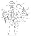
图1是本发明手动按摩吸奶器第一种结构的分解示意图。Fig. 1 is an exploded schematic diagram of the first structure of the manual massage breast pump of the present invention.
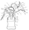
图2是本发明手动按摩吸奶器第一种结构的装配示意图。Fig. 2 is an assembly diagram of the first structure of the manual massage breast pump of the present invention.
图3是本发明手动按摩吸奶器的立体图。Fig. 3 is a perspective view of the manual massage breast pump of the present invention.
图4是本发明手动按摩吸奶器的另一立体图。Fig. 4 is another perspective view of the manual massage breast pump of the present invention.
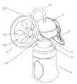
图5是本发明手动按摩吸奶器第二种结构的分解示意图。Fig. 5 is an exploded schematic view of the second structure of the manual massage breast pump of the present invention.
图6是本发明手动按摩吸奶器第二种的结构装配示意图。Fig. 6 is a schematic diagram of the structure and assembly of the second type of manual massage breast pump of the present invention.
主要零部件符号说明:Explanation of main parts symbols:
吸奶器总成1、容置腔11、管路111、底部开口部112、内螺纹1121、微小突出部113、环形鸭嘴阀套114、鸭嘴阀115、支撑件12、转轴121、管道13、气孔131、吸奶罩14、喇叭壁141、包胶手柄2、柄体21、平台211、轴孔22、手柄开槽23、硅胶乳垫3、凹腔31、导气槽32、喇叭壁33、包圈34、套盖35、内衬36、外衬37、连杆4、横杆41、第一卡槽42、第二卡槽43、吸奶泵5、扣位51、凹腔52、装配孔位53、气囊6、气孔61、吸奶器上盖7、嵌槽71、嵌槽72、气孔73、奶瓶8、外螺纹81、气管9 。Breast pump assembly 1, accommodating cavity 11,
具体实施方式Detailed ways
本发明下面将结合附图作进一步详述:The present invention will be described in further detail below in conjunction with accompanying drawing:
图1~图4示出了本发明的第一个实施例。1 to 4 show a first embodiment of the present invention.
请参阅附图所示,所述手动按摩吸奶器由吸奶器总成1、容置腔11、吸奶罩14、包胶手柄2、平台211、硅胶乳垫3、连杆4、横杆41、第一卡槽42、第二卡槽43、吸奶泵5、扣位51、凹腔52、装配孔位53、手柄开槽23、气囊6、气孔61、吸奶器上盖7、奶瓶8、气管9组成,其中:吸奶器总成1由吸奶器中央部位成型的容置腔11、该容置腔11的一侧壁向上斜向凸设的支撑件12、该支撑件12顶部设有带轴孔供包胶手柄2枢接的转轴121、该容置腔11另一侧壁向上斜向凸设与容置腔11贯通的外凸管道13及该管道13端部成型逐渐扩大为喇叭壁141的吸奶罩14、当硅胶乳垫3的对应喇叭壁33部分装入吸奶罩14的喇叭壁141后在二者间形成的导气槽32及吸奶罩14与管道14结合部开设的气孔131、该容置腔11的底部凸设与容置腔11贯通的环形鸭嘴阀套114、该环形鸭嘴阀套114的外壁套装的鸭嘴阀115、容置腔11的底部经管路111向下成型设置内螺纹1121且形似奶瓶盖以便于螺接奶瓶8口端的底部开口部112、该容置腔11内自下而上套装的吸奶泵组件、设有气孔61的气囊6、该容置腔11顶部开口端套装用于封闭腔体并分别在包胶手柄2及吸奶罩管道13部位开设嵌槽71、72并在顶部开设气孔73的吸奶器上盖7、分别连接在吸奶罩气孔131与穿设吸奶器上盖气孔73与气囊6的气孔61间的一段气管9组成。Please refer to the accompanying drawings, the manual massage breast pump is composed of a breast pump assembly 1, an accommodating chamber 11, a
吸奶泵组件由套装在吸奶器容置腔11下部的吸奶泵5、该吸奶泵5开口端向外成型用于扣接吸奶器容置腔11顶部向外凸设微小突出部113而成型凹位所弯折的扣位51、吸奶泵5底部整体向上内凹以形成供倒T型连杆4的横杆41紧贴定位的盆底底部凹腔52并在圆心部位向上凸设贯通于凹腔52的装配孔位53、倒T型连杆4的顶部和中部分别成型以扩大直径的凸柱而形成供包胶手柄2水平段端部开槽嵌套的第一卡槽42和供吸奶泵5底部装配孔位53嵌套的第二卡槽43组成;所述吸奶泵连杆4从吸奶泵底部装配孔位53套入后,装入吸奶器总成上端开口处。The breast pump assembly consists of a breast pump 5 set in the lower part of the breast pump chamber 11, and the opening end of the breast pump 5 is outwardly formed for fastening to the top of the breast pump chamber 11 with a small protrusion protruding outward. 113 and the
硅胶乳垫3的喇叭壁33上成型有数个凸出以形成气泡状薄壁的凹腔31,乳垫的喇叭壁33边缘向外包覆状成型用于套接吸奶罩14喇叭口口端的包圈34。考虑到卫生的需要,套装在吸奶罩14喇叭壁141上的乳垫喇叭壁33口端套装有防尘的套盖35,设置气泡状薄壁的结构可在气体的作用下对乳房进行按摩,促进乳汁的分泌。The
包胶手柄2由一在上端垂直弯折的柄体21、弯折部分的内槽中成型有一形似蛋形剖面并在其中间部位分别凹设一对供吸奶器总成容置腔11一侧壁向上斜向凸设的支撑件转轴121嵌套的轴孔22、柄体21顶端呈水平延伸的平台211、该平台211上开设用于套装在吸奶泵连杆4顶部第一卡槽42内的手柄开槽23组成;所述包胶手柄开槽23与吸奶泵连杆4的第一卡槽42卡好后,将包胶手柄2的一对轴孔22对准吸奶器总成的转轴121装入。The rubber-coated
装配过程:硅胶乳垫3装于吸奶罩的喇叭壁141中;吸奶泵组件的连杆4从吸奶泵5的吸奶泵装配孔位53处装入后连接于吸奶泵组件顶端开口;包胶手柄2的手柄开槽23与吸奶泵组件的连杆4的第一卡槽42卡好后将手柄安装轴孔22对准支撑件12的转轴121装入;气囊6将气孔61从吸奶器上盖7的气孔73处装入,然后盖于吸奶泵扣位51处;气管9将两端分别装于气囊气孔61与吸奶器上盖气孔73上;口部带有外螺纹81的奶瓶8装配于吸奶器总成1的带内螺纹1121的底部开口部112。Assembly process: the
手动按摩吸奶器的动作如下:The manual massage breast pump works as follows:
当用户压下包胶手柄2时,手柄开槽23带动吸奶泵组件的连杆4向上运动,吸奶泵组件的连杆4拉动吸奶泵5往上运动,使吸奶器总成1内气压降低,同时包胶手柄2压迫气囊6,使气囊6内部的体积减小,气压增大,气体通过气囊气孔61与吸奶器上盖气孔73经过气管9由气孔131处进入硅胶乳垫3,由导气槽32进入气泡状薄壁的凹腔31,在气泡状薄壁气压增加和吸奶器总成1气压减小的共同作用下,气泡状薄壁往内挤压乳池,起到按摩乳晕挤出乳汁的作用。When the user presses the
当用户松开包胶手柄2时,因气囊6和硅胶乳垫3本身材料的回弹和乳房对硅胶乳垫气泡状薄壁的反弹,气泡状薄壁内的气体由气管9返回至气囊6内部,达到气压的平衡。重复以上步骤,就能使手动按摩吸奶器达到吸奶和按摩同时进行的作用。When the user releases the
图5~图6示出了本发明的第二个实施例。5 to 6 show a second embodiment of the present invention.
请参阅附图所示,该实施例与第一实施例的区别仅在于,所述吸奶罩14与管道13之间螺纹连接。所述乳垫3由成型数个凸出以形成气泡状薄壁的凹腔31构成的喇叭壁33整体包覆吸奶罩14外壁的内衬36、带有气孔131且整体包覆内衬36的外衬37、乳垫内衬36与外衬37之间成型的导气槽32组成。其它结构同第一实施例,此处略。Please refer to the drawings, the difference between this embodiment and the first embodiment is only that the
以上所述仅为本发明的较佳实施例,凡依本发明权利要求范围所做的均等变化与修饰,皆应属本发明权利要求的涵盖范围。The above descriptions are only preferred embodiments of the present invention, and all equivalent changes and modifications made according to the scope of the claims of the present invention shall fall within the scope of the claims of the present invention.
Claims (8)
Priority Applications (2)
| Application Number | Priority Date | Filing Date | Title |
|---|---|---|---|
| CN2011100029222ACN102068721A (en) | 2011-01-08 | 2011-01-08 | manual massage breast pump |
| US13/113,016US8187219B1 (en) | 2011-01-08 | 2011-05-20 | Massaging manual breast pump |
Applications Claiming Priority (1)
| Application Number | Priority Date | Filing Date | Title |
|---|---|---|---|
| CN2011100029222ACN102068721A (en) | 2011-01-08 | 2011-01-08 | manual massage breast pump |
Publications (1)
| Publication Number | Publication Date |
|---|---|
| CN102068721Atrue CN102068721A (en) | 2011-05-25 |
Family
ID=44027602
Family Applications (1)
| Application Number | Title | Priority Date | Filing Date |
|---|---|---|---|
| CN2011100029222APendingCN102068721A (en) | 2011-01-08 | 2011-01-08 | manual massage breast pump |
Country Status (2)
| Country | Link |
|---|---|
| US (1) | US8187219B1 (en) |
| CN (1) | CN102068721A (en) |
Cited By (11)
| Publication number | Priority date | Publication date | Assignee | Title |
|---|---|---|---|---|
| CN102309784A (en)* | 2011-09-23 | 2012-01-11 | 李红彪 | Manual breast pump |
| CN103656769A (en)* | 2012-09-14 | 2014-03-26 | 玛帕有限公司 | Manual breast pump |
| CN105079897A (en)* | 2015-09-16 | 2015-11-25 | 广州市华怡橡塑制品有限公司 | Health multi-purpose breast pump |
| WO2018006630A1 (en)* | 2016-07-07 | 2018-01-11 | 东莞亲亲我实业有限公司 | Breast pad, bra body, and breast pump |
| CN107874787A (en)* | 2017-11-10 | 2018-04-06 | 四川大学华西医院 | Hydrops collection system |
| CN108478403A (en)* | 2018-02-02 | 2018-09-04 | 李阅 | A kind of gynemetrics puerpera prevents long-pending milk equipment |
| CN109152872A (en)* | 2016-05-11 | 2019-01-04 | 贝亲株式会社 | Hand-operated breast pump |
| CN110538352A (en)* | 2019-09-29 | 2019-12-06 | 佛山市顺德区锐腾电器制造股份有限公司 | breast pump |
| CN111701098A (en)* | 2020-07-08 | 2020-09-25 | 方国峰 | Milk bowl and breast pump |
| CN114650851A (en)* | 2019-11-14 | 2022-06-21 | 贝亲株式会社 | Breast pump |
| US12280187B2 (en) | 2022-01-04 | 2025-04-22 | Microjet Technology Co., Ltd. | Breast pump |
Families Citing this family (12)
| Publication number | Priority date | Publication date | Assignee | Title |
|---|---|---|---|---|
| US6749582B2 (en) | 2002-04-30 | 2004-06-15 | The First Years Inc. | Pumping breast milk |
| US8398584B2 (en) | 2009-01-16 | 2013-03-19 | Learning Curve Brands, Inc. | Breast pump and method of use |
| US8623028B2 (en)* | 2009-09-23 | 2014-01-07 | Intuitive Surgical Operations, Inc. | Surgical port feature |
| EP2946798B1 (en)* | 2013-01-17 | 2019-01-02 | Pigeon Corporation | Manual breastpump |
| RU2561292C1 (en)* | 2014-05-26 | 2015-08-27 | Михаил Олегович Мамонтов | Method of hydrotherapy cavitation action and device for its implementation |
| US10828407B2 (en) | 2014-06-23 | 2020-11-10 | Momgenuity, Llc | Breast pump kit |
| US10258723B2 (en) | 2016-07-08 | 2019-04-16 | DAO Health | Submersible breast pump protection mechanism for a breast milk collection device with self-contained reservoir |
| US10994875B2 (en)* | 2016-10-19 | 2021-05-04 | DAO Health | Device and method for transferring breast milk from an irregular shaped reservoir assembly for storage or feeding |
| US12005166B2 (en)* | 2017-01-11 | 2024-06-11 | Momtech Inc. | Breast pump |
| CA3089827A1 (en)* | 2018-01-29 | 2019-08-01 | Sherri Levine | Breast pump kit |
| US20190365609A1 (en)* | 2018-05-31 | 2019-12-05 | BeauGen, LLC | Method and apparatus for a nipple cushion |
| USD898184S1 (en) | 2019-01-29 | 2020-10-06 | Handi-Craft Company | Breast pump valve |
Citations (5)
| Publication number | Priority date | Publication date | Assignee | Title |
|---|---|---|---|---|
| US6749582B2 (en)* | 2002-04-30 | 2004-06-15 | The First Years Inc. | Pumping breast milk |
| WO2004058330A1 (en)* | 2002-12-27 | 2004-07-15 | Mamma Lactans As | Manual breast pump |
| CN1662268A (en)* | 2002-08-29 | 2005-08-31 | 贝亲株式会社 | manual breast pump |
| CN101232909A (en)* | 2005-08-09 | 2008-07-30 | 贝亲株式会社 | Milking device |
| CN201987937U (en)* | 2011-01-08 | 2011-09-28 | 蒋一新 | manual massage breast pump |
Family Cites Families (3)
| Publication number | Priority date | Publication date | Assignee | Title |
|---|---|---|---|---|
| GB0214525D0 (en)* | 2002-06-24 | 2002-08-07 | Samson Ilan | Breast pump |
| JP4969262B2 (en)* | 2007-02-08 | 2012-07-04 | ピジョン株式会社 | Milking machine |
| CN201064581Y (en)* | 2007-07-04 | 2008-05-28 | 程克勇 | Manual breast pump |
- 2011
- 2011-01-08CNCN2011100029222Apatent/CN102068721A/enactivePending
- 2011-05-20USUS13/113,016patent/US8187219B1/ennot_activeExpired - Fee Related
Patent Citations (5)
| Publication number | Priority date | Publication date | Assignee | Title |
|---|---|---|---|---|
| US6749582B2 (en)* | 2002-04-30 | 2004-06-15 | The First Years Inc. | Pumping breast milk |
| CN1662268A (en)* | 2002-08-29 | 2005-08-31 | 贝亲株式会社 | manual breast pump |
| WO2004058330A1 (en)* | 2002-12-27 | 2004-07-15 | Mamma Lactans As | Manual breast pump |
| CN101232909A (en)* | 2005-08-09 | 2008-07-30 | 贝亲株式会社 | Milking device |
| CN201987937U (en)* | 2011-01-08 | 2011-09-28 | 蒋一新 | manual massage breast pump |
Cited By (15)
| Publication number | Priority date | Publication date | Assignee | Title |
|---|---|---|---|---|
| CN102309784A (en)* | 2011-09-23 | 2012-01-11 | 李红彪 | Manual breast pump |
| CN103656769A (en)* | 2012-09-14 | 2014-03-26 | 玛帕有限公司 | Manual breast pump |
| CN103656769B (en)* | 2012-09-14 | 2018-03-09 | 玛帕有限公司 | Manual breast pump |
| CN105079897A (en)* | 2015-09-16 | 2015-11-25 | 广州市华怡橡塑制品有限公司 | Health multi-purpose breast pump |
| CN109152872B (en)* | 2016-05-11 | 2022-02-18 | 贝亲株式会社 | Manual breast pump |
| CN109152872A (en)* | 2016-05-11 | 2019-01-04 | 贝亲株式会社 | Hand-operated breast pump |
| WO2018006630A1 (en)* | 2016-07-07 | 2018-01-11 | 东莞亲亲我实业有限公司 | Breast pad, bra body, and breast pump |
| CN107874787A (en)* | 2017-11-10 | 2018-04-06 | 四川大学华西医院 | Hydrops collection system |
| CN108478403A (en)* | 2018-02-02 | 2018-09-04 | 李阅 | A kind of gynemetrics puerpera prevents long-pending milk equipment |
| CN108478403B (en)* | 2018-02-02 | 2020-05-15 | 青岛市妇女儿童医院(青岛市妇幼保健院、青岛市残疾儿童医疗康复中心、青岛市新生儿疾病筛查中心) | Milk accumulation preventing equipment for puerpera in obstetrics and gynecology department |
| CN110538352A (en)* | 2019-09-29 | 2019-12-06 | 佛山市顺德区锐腾电器制造股份有限公司 | breast pump |
| CN110538352B (en)* | 2019-09-29 | 2024-01-12 | 佛山市顺德区锐腾电器制造股份有限公司 | Breast pump |
| CN114650851A (en)* | 2019-11-14 | 2022-06-21 | 贝亲株式会社 | Breast pump |
| CN111701098A (en)* | 2020-07-08 | 2020-09-25 | 方国峰 | Milk bowl and breast pump |
| US12280187B2 (en) | 2022-01-04 | 2025-04-22 | Microjet Technology Co., Ltd. | Breast pump |
Also Published As
| Publication number | Publication date |
|---|---|
| US8187219B1 (en) | 2012-05-29 |
Similar Documents
| Publication | Publication Date | Title |
|---|---|---|
| CN102068721A (en) | manual massage breast pump | |
| US7988661B2 (en) | Breastshield with multi-pressure and expansible chamber construction, related breastpump and method | |
| CN103025363B (en) | Breast pump | |
| US20090062731A1 (en) | Breast Pump | |
| AU2002322292A1 (en) | Breastshield with Multi-pressure and Expansible Chamber Construction, Related Breastpump and Method | |
| JP2012529955A (en) | Milker insert | |
| CN201987937U (en) | manual massage breast pump | |
| CN217697447U (en) | Wearable breast pump | |
| CN215504691U (en) | Built-in negative pressure type breast pump | |
| CN112295029B (en) | Suction hood and breast pump comprising same | |
| CN214181304U (en) | Breast pump | |
| WO2013163855A1 (en) | A nipple with pressure-adjusting valve | |
| CN211610818U (en) | 3D nipple | |
| CN113577420B (en) | Built-in negative pressure type breast pump | |
| CN215938509U (en) | Breast pump and breast pump | |
| US20180352982A1 (en) | Drink containers | |
| CN219481050U (en) | Wearable breast pump | |
| US20190231101A1 (en) | Drink containers | |
| US20180132639A1 (en) | Drink Containers | |
| CN221713047U (en) | Wearable Breast Pump | |
| CN202875901U (en) | Breast pump | |
| CN221357769U (en) | Eccentric nipple | |
| CN223196367U (en) | A breast pump | |
| CN209996870U (en) | Ergonomic-based breast pump | |
| WO2025086543A1 (en) | Breast pumping apparatus, breast pump, and nipple protecting shield |
Legal Events
| Date | Code | Title | Description |
|---|---|---|---|
| C06 | Publication | ||
| PB01 | Publication | ||
| C10 | Entry into substantive examination | ||
| SE01 | Entry into force of request for substantive examination | ||
| C02 | Deemed withdrawal of patent application after publication (patent law 2001) | ||
| WD01 | Invention patent application deemed withdrawn after publication | Application publication date:20110525 |